EP3276755A1 - Partie de cosse de raccordement pour une unité de cosse de raccordement blindée - Google Patents
Partie de cosse de raccordement pour une unité de cosse de raccordement blindée Download PDFInfo
- Publication number
- EP3276755A1 EP3276755A1 EP17181741.4A EP17181741A EP3276755A1 EP 3276755 A1 EP3276755 A1 EP 3276755A1 EP 17181741 A EP17181741 A EP 17181741A EP 3276755 A1 EP3276755 A1 EP 3276755A1
- Authority
- EP
- European Patent Office
- Prior art keywords
- plug connection
- electrically conductive
- insulating body
- protective conductor
- locking sleeve
- Prior art date
- Legal status (The legal status is an assumption and is not a legal conclusion. Google has not performed a legal analysis and makes no representation as to the accuracy of the status listed.)
- Withdrawn
Links
Images


Classifications
-
- H—ELECTRICITY
- H01—ELECTRIC ELEMENTS
- H01R—ELECTRICALLY-CONDUCTIVE CONNECTIONS; STRUCTURAL ASSOCIATIONS OF A PLURALITY OF MUTUALLY-INSULATED ELECTRICAL CONNECTING ELEMENTS; COUPLING DEVICES; CURRENT COLLECTORS
- H01R13/00—Details of coupling devices of the kinds covered by groups H01R12/70 or H01R24/00 - H01R33/00
- H01R13/648—Protective earth or shield arrangements on coupling devices, e.g. anti-static shielding
- H01R13/658—High frequency shielding arrangements, e.g. against EMI [Electro-Magnetic Interference] or EMP [Electro-Magnetic Pulse]
- H01R13/6581—Shield structure
- H01R13/6582—Shield structure with resilient means for engaging mating connector
-
- H—ELECTRICITY
- H01—ELECTRIC ELEMENTS
- H01R—ELECTRICALLY-CONDUCTIVE CONNECTIONS; STRUCTURAL ASSOCIATIONS OF A PLURALITY OF MUTUALLY-INSULATED ELECTRICAL CONNECTING ELEMENTS; COUPLING DEVICES; CURRENT COLLECTORS
- H01R13/00—Details of coupling devices of the kinds covered by groups H01R12/70 or H01R24/00 - H01R33/00
- H01R13/648—Protective earth or shield arrangements on coupling devices, e.g. anti-static shielding
- H01R13/658—High frequency shielding arrangements, e.g. against EMI [Electro-Magnetic Interference] or EMP [Electro-Magnetic Pulse]
- H01R13/6591—Specific features or arrangements of connection of shield to conductive members
- H01R13/6596—Specific features or arrangements of connection of shield to conductive members the conductive member being a metal grounding panel
-
- H—ELECTRICITY
- H01—ELECTRIC ELEMENTS
- H01R—ELECTRICALLY-CONDUCTIVE CONNECTIONS; STRUCTURAL ASSOCIATIONS OF A PLURALITY OF MUTUALLY-INSULATED ELECTRICAL CONNECTING ELEMENTS; COUPLING DEVICES; CURRENT COLLECTORS
- H01R13/00—Details of coupling devices of the kinds covered by groups H01R12/70 or H01R24/00 - H01R33/00
- H01R13/46—Bases; Cases
- H01R13/52—Dustproof, splashproof, drip-proof, waterproof, or flameproof cases
- H01R13/521—Sealing between contact members and housing, e.g. sealing insert
-
- H—ELECTRICITY
- H01—ELECTRIC ELEMENTS
- H01R—ELECTRICALLY-CONDUCTIVE CONNECTIONS; STRUCTURAL ASSOCIATIONS OF A PLURALITY OF MUTUALLY-INSULATED ELECTRICAL CONNECTING ELEMENTS; COUPLING DEVICES; CURRENT COLLECTORS
- H01R13/00—Details of coupling devices of the kinds covered by groups H01R12/70 or H01R24/00 - H01R33/00
- H01R13/56—Means for preventing chafing or fracture of flexible leads at outlet from coupling part
- H01R13/562—Bending-relieving
-
- H—ELECTRICITY
- H01—ELECTRIC ELEMENTS
- H01R—ELECTRICALLY-CONDUCTIVE CONNECTIONS; STRUCTURAL ASSOCIATIONS OF A PLURALITY OF MUTUALLY-INSULATED ELECTRICAL CONNECTING ELEMENTS; COUPLING DEVICES; CURRENT COLLECTORS
- H01R13/00—Details of coupling devices of the kinds covered by groups H01R12/70 or H01R24/00 - H01R33/00
- H01R13/62—Means for facilitating engagement or disengagement of coupling parts or for holding them in engagement
- H01R13/625—Casing or ring with bayonet engagement
-
- H—ELECTRICITY
- H01—ELECTRIC ELEMENTS
- H01R—ELECTRICALLY-CONDUCTIVE CONNECTIONS; STRUCTURAL ASSOCIATIONS OF A PLURALITY OF MUTUALLY-INSULATED ELECTRICAL CONNECTING ELEMENTS; COUPLING DEVICES; CURRENT COLLECTORS
- H01R13/00—Details of coupling devices of the kinds covered by groups H01R12/70 or H01R24/00 - H01R33/00
- H01R13/648—Protective earth or shield arrangements on coupling devices, e.g. anti-static shielding
- H01R13/652—Protective earth or shield arrangements on coupling devices, e.g. anti-static shielding with earth pin, blade or socket
-
- H—ELECTRICITY
- H01—ELECTRIC ELEMENTS
- H01R—ELECTRICALLY-CONDUCTIVE CONNECTIONS; STRUCTURAL ASSOCIATIONS OF A PLURALITY OF MUTUALLY-INSULATED ELECTRICAL CONNECTING ELEMENTS; COUPLING DEVICES; CURRENT COLLECTORS
- H01R13/00—Details of coupling devices of the kinds covered by groups H01R12/70 or H01R24/00 - H01R33/00
- H01R13/648—Protective earth or shield arrangements on coupling devices, e.g. anti-static shielding
- H01R13/658—High frequency shielding arrangements, e.g. against EMI [Electro-Magnetic Interference] or EMP [Electro-Magnetic Pulse]
- H01R13/6591—Specific features or arrangements of connection of shield to conductive members
- H01R13/6597—Specific features or arrangements of connection of shield to conductive members the conductive member being a contact of the connector
-
- H—ELECTRICITY
- H01—ELECTRIC ELEMENTS
- H01R—ELECTRICALLY-CONDUCTIVE CONNECTIONS; STRUCTURAL ASSOCIATIONS OF A PLURALITY OF MUTUALLY-INSULATED ELECTRICAL CONNECTING ELEMENTS; COUPLING DEVICES; CURRENT COLLECTORS
- H01R2107/00—Four or more poles
-
- H—ELECTRICITY
- H01—ELECTRIC ELEMENTS
- H01R—ELECTRICALLY-CONDUCTIVE CONNECTIONS; STRUCTURAL ASSOCIATIONS OF A PLURALITY OF MUTUALLY-INSULATED ELECTRICAL CONNECTING ELEMENTS; COUPLING DEVICES; CURRENT COLLECTORS
- H01R24/00—Two-part coupling devices, or either of their cooperating parts, characterised by their overall structure
- H01R24/28—Coupling parts carrying pins, blades or analogous contacts and secured only to wire or cable
- H01R24/30—Coupling parts carrying pins, blades or analogous contacts and secured only to wire or cable with additional earth or shield contacts
-
- H—ELECTRICITY
- H01—ELECTRIC ELEMENTS
- H01R—ELECTRICALLY-CONDUCTIVE CONNECTIONS; STRUCTURAL ASSOCIATIONS OF A PLURALITY OF MUTUALLY-INSULATED ELECTRICAL CONNECTING ELEMENTS; COUPLING DEVICES; CURRENT COLLECTORS
- H01R43/00—Apparatus or processes specially adapted for manufacturing, assembling, maintaining, or repairing of line connectors or current collectors or for joining electric conductors
- H01R43/20—Apparatus or processes specially adapted for manufacturing, assembling, maintaining, or repairing of line connectors or current collectors or for joining electric conductors for assembling or disassembling contact members with insulating base, case or sleeve
Definitions
- the invention relates to a plug connection part for a shielded plug connection unit which has an insulating body and a plurality of electrical plug contacts which are connected to electrical cable ends, wherein an electrical plug contact is designed as a protective conductor contact, as well as with an electrically conductive shielding, which surrounds the insulating body on the outside.
- a multipolar connector unit is from the DE 10 2012 203 459 A1 known.
- the known connector unit has two mutually complementary connector parts.
- the two plug connection parts each have a monolithic insulating body, in each of which electrical plug contacts, including a protective conductor contact, are integrated.
- the two insulating body of the two connector parts are axially plugged into each other.
- the respective electrical plug contacts are firmly connected to corresponding cable ends of an electric cable.
- a locking sleeve is additionally provided, which is held on one of the two connector parts and can be latched with an outer jacket of the other connector part.
- the cable ends are connected to each other via shielded connector parts.
- the object of the invention is to provide a connector part, a shielded connector unit and a locking sleeve of the type mentioned, which allow a simple and safe electromagnetic shielding.
- the connector part in that the protective conductor contact center is arranged inside the insulating body and surrounded by the other electrical plug contacts on the outside, and that the protective conductor contact is electrically contacted by means of at least one electrically conductive radial web to the shield.
- the central arrangement of the protective conductor contact is advantageous in electrical terms.
- the connection of the protective conductor contact via at least one electrically conductive radial web outwards to the shielding jacket ensures reliable grounding.
- the solution according to the invention is suitable for multipolar plug-in connection units for industrial cabling of machines and plants.
- the connector part according to the invention can be used in conjunction with the shielded connector unit for three-phase AC systems.
- the connector part and the corresponding connector unit are designed for the transmission of voltage up to 630 volts and currents up to 16 amperes.
- the plug connection part according to the invention is used for plug connection units which are used for power and signal transmission of machine tools.
- the at least one radial web is resiliently biased in the assembled operating state.
- the electrical contacting of the radial web is carried out only by mechanical contact with the protective conductor contact and the outside shielding.
- the elastic bias of the at least one radial web is provided.
- a metallic leaf spring element is provided as a radial web.
- the metallic leaf spring element on the one hand has sufficient electrical conductivity. On the other hand, it allows a simple elastic preload.
- a plurality of identically designed leaf spring elements are provided which - distributed over a circumference of the insulating body - protrude in different radial directions from the central protective conductor to the outside.
- three identically designed leaf spring elements are provided which protrude radially from the center conductor serving as a central protective conductor radially outward.
- each leaf spring element has a U-shaped curved biasing portion and at its opposite ends each have a radially outwardly or inwardly projecting contacting.
- the curved biasing portion and the contacting portions adjoin each other as viewed along the length of the leaf spring member.
- the leaf spring element is made in one piece, including the biasing portion and the two contacting portions.
- the insulating body has at least one radially extending receiving pocket, in which the leaf spring element is inserted.
- the insulating body is monolithic made of a suitable plastic material.
- the at least one radially extending receiving pocket is already formed in the production of the insulating body in the insulating body.
- the number of receiving pockets, which are provided in the insulating body corresponds to the number of leaf spring elements which are inserted into the insulating body.
- the receiving pocket is designed slit-shaped and has a receiving opening to the outside, which is dimensioned so that the leaf spring element with the biasing portion and the radially inwardly projecting Whyierabites radially from the outside can be inserted, and the receiving pocket has inwardly a contact opening towards the protective conductor towards, which is tuned in its dimensioning on the inwardly projecting Whyierabites.
- the outside receiving opening of the receiving pocket has a width which corresponds at least to the width of the U-shaped curved biasing portion of the leaf spring element, since the leaf spring element in the region of the biasing portion has the largest width.
- the contact opening of the receiving pocket inwardly must have a substantially smaller width, which is adapted only to the dimensioning of the justifyierabiteses.
- the underlying object of the invention is achieved in that the locking sleeve made of plastic and with an electrically conductive outer layer and is provided with an electrically conductive inner layer.
- the production of the locking sleeve made of plastic allows a simple and cost-effective production in large quantities.
- the coating of the locking sleeve inside and outside, each with an electrically conductive layer allows the desired shielding and the desired electrically conductive contact with the respective electrically conductive shielding shell of the two connector parts and consequently also with the respective protective conductor.
- the electrically conductive outer layer has a greater layer thickness than the electrically conductive inner layer. Characterized in that the electrically conductive inner layer has a lower layer thickness than the electrically conductive outer layer, a greater elasticity is given for inside functional sections of the locking sleeve, so that a functionality corresponding elastic functional sections on the inner surface of the locking sleeve is not or almost not impaired.
- a layer thickness of the outer layer is preferably in a range of 50 .mu.m to 150 .mu.m and a layer thickness of the inner layer in a range of 20 .mu.m to 50 .mu.m.
- a ratio between outside and inside layer thickness is preferably in the range between 2: 1 and 5: 1.
- both the outer layer and the inner layer as galvanic coatings of an outer circumference and an inner circumference of Locking sleeve designed.
- Corresponding galvanic coatings are metallic and therefore electrically conductive.
- the locking sleeve is provided on its inner circumference with at least one integrally formed, resiliently movable latching lug, which is coated with the electrically conductive inner layer.
- the integrally molded, resiliently movable locking lug provided an elastic functional portion of the locking sleeve, as described above.
- the object underlying the invention is achieved in that the locking sleeve is provided with the features of at least one of the previously described embodiments or refinements.
- the locking sleeve can be manufactured as a separate component and mounted on a corresponding connector part of the connector unit. Such a locking sleeve is also disassembled from the respective connector part and therefore interchangeable.
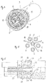
- a shielded connector unit according to the Fig. 1 to 8 a connector part 1, which will be described in more detail below.
- the plug connection unit also has an unillustrated, complementary plug connection part which is functionally identical in design to the plug connection part 1. Only the functional parts and sections relating to the plug function are complementary in the plug connection part, not shown, to the corresponding functional parts and sections of the plug connection part 1, to allow a secure axial nesting of the two connector parts and a secure electrical contact electrical plug contacts, which are - like the other functional parts and sections of the complementary connector part, designed so complementary that a female connector part 1 on the one hand and a male, not shown Plug connector part other hand.
- the following explanations therefore apply in the same way for the not shown, complementary connector part.
- Each connector part 1 is connected to a respective cable end 2 of an electric cable having a plurality of cable strands 3, 4.
- a cable strand is formed by a protective conductor 3.
- a total of five more cable strands 4 are provided.
- the cable strands serve for signal transmission and energy transmission. If no signal transmission is required, the cable can also be provided only four-wire with four cable strands.
- the cable strands 4 of the cable end 2 are connected to electrical plug contacts 6, wherein the cable strands 4 are preferably connected to the electrical plug contacts 6 by crimping.
- PE conductor protective conductor 3 opens into a centrally arranged protective conductor contact 5, wherein a corresponding stripped cable strand of the protective conductor 3 is crimped in the same way with the protective conductor contact 5 as the cable strands 4 with the electrical plug contacts 6.
- the protective conductor contact 5 is identical like the plug contacts 6, but is arranged centrally between the plug contacts 6, which surround the central protective conductor contact 5 radially on the outside - seen in the circumferential direction.
- the protective conductor contact 5 is positioned at least substantially coaxially to a central longitudinal axis M of the plug connection part 1.
- the terms radial and axial are each related to the central longitudinal axis M.
- a shrink tube piece 10 is also provided, which is designed as an adhesive shrink tubing and serves as an adhesion promoter. Instead of an adhesive hosiery hose, an adhesive application may also be provided.
- Both the five electrical plug contacts 6 and the central protective conductor contact 5 are axially inserted into corresponding receptacles of a monolithic insulating body 7, which is made of a plastic material.
- the electrical plug contacts 6 as well as the protective conductor contact 5 are formed by corresponding metal sleeves.
- a carrier sleeve 9 is axially latched. Between the support sleeve 9 and an outer jacket of the insulating body 7, a sealing ring 11 is arranged ( Fig. 1 and 2 ).
- the carrier sleeve 9 is galvanically coated to form part of an electrically conductive shielding jacket of the connector part 1.
- the support sleeve 9 as well as the cable end 2 is also associated with an electrically conductive shielding film 8, which surrounds the cable end 2 and the support sleeve 9 and thus the insulating body 7 at least partially.
- the electrically conductive shielding film 8 forms a further part of the electrically conductive shielding jacket.
- the support sleeve 9 is made of plastic and has by the galvanic coating on an electrically conductive surface both in the region of its inner circumference and in the region of its outer periphery. A layer thickness of the galvanic coating of the carrier sleeve 9 is executed the same inside and outside.
- a locking sleeve 13 is movably supported, which is made of a plastic material and serves to lock the connector part 1 in mated condition with the complementary connector part and thus secure the connector part 1 against the complementary connector part axially.
- the locking sleeve 13 is made of plastic and has an electrically conductive surface both in the region of its inner circumference and in the region of its outer periphery by a galvanic coating, which will be discussed in more detail below.
- the insulating body 7 has distributed over its circumference a total of three slot-shaped receiving pockets 20 which extend in different radial planes relative to the central longitudinal axis M, and which are aligned in different directions to each other. Based on FIGS. 2 and 3 as well as on the basis of Fig. 6 is clearly seen that each of the three receiving pockets 20 axially to the central longitudinal axis M seen radially from the outside have a large length, which reduces radially inwardly to the protective conductor contact 5 stepwise. A width of each slot-shaped receiving pocket 20 is identical over an entire axial and radial extent of the receiving pocket 20.
- Each leaf spring element 19 constitutes a one-part, electrically conductive component, in particular a metal component.
- Each leaf spring element 19 is preferably made of beryllium copper.
- Each leaf spring element 19 has a radially inwardly contacting portion 23 which is extended radially inwardly in the manner of a web relative to the central longitudinal axis M. At this contacting portion 23 includes a U-shaped biasing portion 22 which has an approximately semicircular curvature in the plane of the receiving pocket 20.
- the U-shaped biasing portion 22 has a radially inwardly U-leg and a radially outer U-leg, wherein the radially inwardly U-legs integrally connected to the inner contacting portion 23.
- the radially outer U-leg opens into a radially outer justifyierabêt 21 which is designed in the manner of a hook nose.
- the two contacting portions 21 and 23 as well as the biasing portion 22 are aligned in a common plane.
- the biasing portion 22 allows an elastically resilient mobility of its two U-legs, so that the leaf spring element 19 can be set by appropriate radial load from the inside and from the outside under bias.
- the configured as Hakennasen, radially outer justifyierabête 21 project in the unloaded resting state of the leaf spring elements 19 slightly radially over an outer jacket of the insulating body 7.
- the outer contacting portions 21, designed as hook nose are pressed radially inwardly, whereby the leaf spring elements 19 become biased.
- the inner justifyierabête 23 are inevitably pressed radially inwardly against the outer periphery of the protective conductor contact 5, whereby a secure and permanent mechanical contact between the protective conductor contact 5 and the electrically conductive carrier sleeve 9 is provided.
- the connector unit is also associated with the locking sleeve 13, which is based on the FIGS. 7 and 8 is more clearly recognizable.
- the locking sleeve 13 is axially latched in the illustrated embodiment on the support sleeve 9 and limited rotatably held to the support sleeve 9.
- the support sleeve 9 also has in the region of its plug-in receptacle a sealing ring 12, which ensures the seal with the complementary insulating body of the other connector part.
- the locking sleeve 13 is provided on its inner circumference with two partially cut and therefore elastically movable locking lugs 14 which are integrally formed on the inner periphery of the locking sleeve 13. With reference to the drawings, only one locking lug 14 can be seen. Hereinafter, only the recognizable locking lug 14 will be described. For the other detent the same applies accordingly.
- the locking lug 14 is made together with the production of the locking sleeve 13 made of a suitable plastic material.
- the locking sleeve 13 is, as shown in the Fig. 8 is indicated, with an electrically conductive outer layer 24 and coated with an electrically conductive inner layer 25, wherein the electrically conductive inner layer 25 and the locking lug 14 covers.
- Both the inner layer 25 and the outer layer 24 have been created by a galvanic coating of the existing plastic locking sleeve 13.
- the inner layer 25 has a lower layer thickness than the outer layer 24.
- the lower layer provided with inner layer 25 is provided in order to maintain a sufficient elastic mobility of the locking lug 14. Since both the inner layer 25 and the outer layer 24 are metallic, an excessive layer thickness of the inner layer 25 would lead to a reduction or even a failure of the elastic mobility of the locking lug 14.
- the desired elastic mobility of the locking lug 14 is ensured.
- the reduced layer thickness of the inner layer 25 is nevertheless sufficient to achieve the desired electrical conductivity of the locking sleeve 13 in order to continue the shielding of the connector unit also via the locking sleeve as a bridge between the two connector parts.
- the inner layer 25 over the entire inner circumference of the locking sleeve 13 has a uniform layer thickness.
- the locking sleeve 13 has a reduced layer thickness only in the region of the elastically movable functional section on the inside, but has the same layer thickness in the remaining areas as the outer layer.
Landscapes
- Details Of Connecting Devices For Male And Female Coupling (AREA)
Applications Claiming Priority (1)
| Application Number | Priority Date | Filing Date | Title |
|---|---|---|---|
| DE102016213952.5A DE102016213952A1 (de) | 2016-07-28 | 2016-07-28 | Steckverbindungsteil, geschirmte Steckverbindungseinheit und Verriegelungshülse hierfür |
Publications (1)
| Publication Number | Publication Date |
|---|---|
| EP3276755A1 true EP3276755A1 (fr) | 2018-01-31 |
Family
ID=59363045
Family Applications (1)
| Application Number | Title | Priority Date | Filing Date |
|---|---|---|---|
| EP17181741.4A Withdrawn EP3276755A1 (fr) | 2016-07-28 | 2017-07-17 | Partie de cosse de raccordement pour une unité de cosse de raccordement blindée |
Country Status (4)
| Country | Link |
|---|---|
| US (1) | US10153595B2 (fr) |
| EP (1) | EP3276755A1 (fr) |
| CN (1) | CN107666081A (fr) |
| DE (1) | DE102016213952A1 (fr) |
Cited By (6)
| Publication number | Priority date | Publication date | Assignee | Title |
|---|---|---|---|---|
| WO2018192962A1 (fr) * | 2017-04-18 | 2018-10-25 | Phoenix Contact Gmbh & Co. Kg | Assemblage d'une pièce de connecteur à fiches avec insert de contact et élément de mise à la terre |
| CN110061395A (zh) * | 2019-04-29 | 2019-07-26 | 江苏正恺电子科技有限公司 | 一种具有稳固安装结构的连接装置 |
| CN111146623A (zh) * | 2020-03-10 | 2020-05-12 | 江苏正恺电子科技有限公司 | 一种能够实现径向偏转及轴向移动的连接器 |
| CN112803209A (zh) * | 2019-11-14 | 2021-05-14 | 纽陲客股份公司 | 用于电插塞式连接器的触头支架及其触头连接器 |
| US20220166172A1 (en) * | 2019-03-29 | 2022-05-26 | Phoenix Contact Gmbh & Co. Kg | Electrical connector having a contacting element designed as a cast part |
| US12107372B2 (en) * | 2019-03-29 | 2024-10-01 | Phoenix Contact Gmbh & Co. Kg | Electrical connector having a contacting element designed as a cast part |
Families Citing this family (7)
| Publication number | Priority date | Publication date | Assignee | Title |
|---|---|---|---|---|
| IT201600113670A1 (it) * | 2016-11-10 | 2018-05-10 | A A G Stucchi S R L | Gruppo di connessione lineare per conduttori elettrici a elevata affidabilita' di serraggio |
| DE102017104982B3 (de) * | 2017-03-09 | 2018-08-02 | Te Connectivity Industrial Gmbh | Elektrischer Stecker mit spezifischer Erdung von Außenteilen |
| DE102017113875B3 (de) * | 2017-06-22 | 2018-10-18 | Te Connectivity Industrial Gmbh | Elektrischer Stecker mit einem Schutzleiterkontakt und damit einstückig ausgebildeten Schutzleiterverbindungselement zur Erdung von Außenteilen |
| DE102019002660A1 (de) * | 2019-04-10 | 2020-10-15 | Kostal Kontakt Systeme Gmbh | Mehrpoliger elektrischer Steckverbinder |
| CN111628356B (zh) * | 2020-06-05 | 2021-11-16 | 顺科新能源技术股份有限公司 | 屏蔽式连接器 |
| WO2022262482A1 (fr) * | 2021-06-17 | 2022-12-22 | 苏州华旃航天电器有限公司 | Prise antidéflagrante de protection de mise á la terre |
| DE102022203986A1 (de) | 2022-04-25 | 2023-10-26 | Franz Binder GmbH & Co Elektrische Bauelemente Kommanditgesellschaft | Erdungseinrichtung, Erdungseinheit, Kontakteinsatz sowie elektrischer Steckverbinder und Verfahren zur Herstellung eines Kontakteinsatzes |
Citations (7)
| Publication number | Priority date | Publication date | Assignee | Title |
|---|---|---|---|---|
| DE4419023A1 (de) * | 1994-05-31 | 1995-12-07 | Ifm Electronic Gmbh | Einbaustecker |
| DE19528678C1 (de) * | 1995-07-19 | 1997-01-23 | Ifm Electronic Gmbh | Einbaustecker |
| DE20007001U1 (de) * | 2000-04-15 | 2000-07-27 | Anton Hummel Verwaltungs Gmbh, 79183 Waldkirch | Stecker mit einer Hülse |
| EP1063732A1 (fr) * | 1999-06-23 | 2000-12-27 | Amphenol Corporation | Mise à la terre par broche à pression |
| DE10323614A1 (de) * | 2003-01-23 | 2004-08-19 | Hirschmann Electronics Gmbh & Co. Kg | Kabelsteckverbinder |
| DE202005012756U1 (de) * | 2005-08-12 | 2005-10-27 | Anton Hummel Verwaltungs-Gmbh | Stecker mit Haltefeder für einen Erdungskontakt |
| DE102012203459A1 (de) * | 2011-11-09 | 2013-05-16 | Lq Mechatronik-Systeme Gmbh | Mehrpolige Steckverbindungseinheit für Dreiphasen-Wechselstromsysteme |
Family Cites Families (8)
| Publication number | Priority date | Publication date | Assignee | Title |
|---|---|---|---|---|
| US4090759A (en) * | 1975-04-17 | 1978-05-23 | Amp Incorporated | Micro-miniature circular high voltage connector |
| US4116521A (en) * | 1976-10-12 | 1978-09-26 | Amp Incorporated | Miniature universal connector module |
| US4723916A (en) * | 1986-10-23 | 1988-02-09 | E. I. Du Pont De Nemours And Company | Pin plug and socket connector using insulation displacement contacts |
| JP2006513543A (ja) | 2003-01-23 | 2006-04-20 | ヒルシュマン エレクトロニクス ゲゼルシャフト ミット ベシュレンクテル ハフツング ウント コンパニー コマンディートゲゼルシャフト | ケーブル差込み接続器 |
| JP4581947B2 (ja) * | 2005-09-30 | 2010-11-17 | オムロン株式会社 | コネクタ |
| DE202010015763U1 (de) * | 2010-11-17 | 2011-02-17 | Lq Mechatronik-Systeme Gmbh | Vorrichtung zur Positionierung wenigstens eines Rundsteckers |
| DE102011056798B4 (de) * | 2011-12-21 | 2013-07-25 | Phoenix Contact Gmbh & Co. Kg | Geschirmter Steckverbinder und Verfahren zur Herstellung eines geschirmten Steckverbinders |
| DE102013108383C5 (de) * | 2013-08-05 | 2023-04-27 | Harting Electric Stiftung & Co. Kg | Steckverbindermodul |
-
2016
- 2016-07-28 DE DE102016213952.5A patent/DE102016213952A1/de not_active Ceased
-
2017
- 2017-07-17 EP EP17181741.4A patent/EP3276755A1/fr not_active Withdrawn
- 2017-07-26 US US15/660,268 patent/US10153595B2/en not_active Expired - Fee Related
- 2017-07-28 CN CN201710630603.3A patent/CN107666081A/zh active Pending
Patent Citations (7)
| Publication number | Priority date | Publication date | Assignee | Title |
|---|---|---|---|---|
| DE4419023A1 (de) * | 1994-05-31 | 1995-12-07 | Ifm Electronic Gmbh | Einbaustecker |
| DE19528678C1 (de) * | 1995-07-19 | 1997-01-23 | Ifm Electronic Gmbh | Einbaustecker |
| EP1063732A1 (fr) * | 1999-06-23 | 2000-12-27 | Amphenol Corporation | Mise à la terre par broche à pression |
| DE20007001U1 (de) * | 2000-04-15 | 2000-07-27 | Anton Hummel Verwaltungs Gmbh, 79183 Waldkirch | Stecker mit einer Hülse |
| DE10323614A1 (de) * | 2003-01-23 | 2004-08-19 | Hirschmann Electronics Gmbh & Co. Kg | Kabelsteckverbinder |
| DE202005012756U1 (de) * | 2005-08-12 | 2005-10-27 | Anton Hummel Verwaltungs-Gmbh | Stecker mit Haltefeder für einen Erdungskontakt |
| DE102012203459A1 (de) * | 2011-11-09 | 2013-05-16 | Lq Mechatronik-Systeme Gmbh | Mehrpolige Steckverbindungseinheit für Dreiphasen-Wechselstromsysteme |
Cited By (10)
| Publication number | Priority date | Publication date | Assignee | Title |
|---|---|---|---|---|
| WO2018192962A1 (fr) * | 2017-04-18 | 2018-10-25 | Phoenix Contact Gmbh & Co. Kg | Assemblage d'une pièce de connecteur à fiches avec insert de contact et élément de mise à la terre |
| EP3613110B1 (fr) | 2017-04-18 | 2021-11-17 | Phoenix Contact GmbH & Co. KG | Assemblage d'une pièce de connecteur à fiches avec insert de contact et élément de mise à la terre |
| US20220166172A1 (en) * | 2019-03-29 | 2022-05-26 | Phoenix Contact Gmbh & Co. Kg | Electrical connector having a contacting element designed as a cast part |
| US12107372B2 (en) * | 2019-03-29 | 2024-10-01 | Phoenix Contact Gmbh & Co. Kg | Electrical connector having a contacting element designed as a cast part |
| CN110061395A (zh) * | 2019-04-29 | 2019-07-26 | 江苏正恺电子科技有限公司 | 一种具有稳固安装结构的连接装置 |
| CN110061395B (zh) * | 2019-04-29 | 2023-12-05 | 江苏正恺电子科技有限公司 | 一种具有稳固安装结构的连接装置 |
| CN112803209A (zh) * | 2019-11-14 | 2021-05-14 | 纽陲客股份公司 | 用于电插塞式连接器的触头支架及其触头连接器 |
| CN112803209B (zh) * | 2019-11-14 | 2022-12-27 | 纽陲客股份公司 | 用于电插塞式连接器的触头支架及其触头连接器 |
| US11569622B2 (en) | 2019-11-14 | 2023-01-31 | Neutrik Ag | Contact carrier for electrical plug connectors and plug connectors therefor |
| CN111146623A (zh) * | 2020-03-10 | 2020-05-12 | 江苏正恺电子科技有限公司 | 一种能够实现径向偏转及轴向移动的连接器 |
Also Published As
| Publication number | Publication date |
|---|---|
| US20180034212A1 (en) | 2018-02-01 |
| CN107666081A (zh) | 2018-02-06 |
| DE102016213952A1 (de) | 2018-02-01 |
| US10153595B2 (en) | 2018-12-11 |
Similar Documents
| Publication | Publication Date | Title |
|---|---|---|
| EP3276755A1 (fr) | Partie de cosse de raccordement pour une unité de cosse de raccordement blindée | |
| EP3022813B1 (fr) | Répartiteur de puissance électrique pour véhicule électrique ou hybride ainsi que boîtier de répartiteur pour un tel répartiteur de puissance | |
| EP2777096B2 (fr) | Unité de connexion à fiches multipolaire pour systèmes électriques triphasés | |
| DE102017210425A1 (de) | Modulverbinder | |
| DE102009016157B4 (de) | Abgeschirmte Steckverbinderanordnung | |
| DE202005004929U1 (de) | Anschlusselement | |
| EP3614506A1 (fr) | Dispositif de commande pour un véhicule automobile | |
| DE19615158A1 (de) | Steckverbinder für ein Kabel mit wenigstens einer Ader | |
| DE102009016227A1 (de) | Steckverbinder zur Anbindung an ein Koaxialkabel | |
| EP3416249B1 (fr) | Traversée de câble et appareil de contrôle | |
| DE202017101060U1 (de) | Steckverbinder, insbesondere für eine Hochstromanwendung | |
| EP3477777B1 (fr) | Ligne électrique pourvue d'un terminal de blindage | |
| EP2099099B1 (fr) | Elément de connexion électrique doté d'un câble électrique connecté | |
| EP2463959B1 (fr) | Connecteur | |
| DE112017005162B4 (de) | Durchgangsverbinderanordnung | |
| DE102009056713A1 (de) | Steckverbinder-Einrichtung | |
| DE4224155C2 (de) | Elektrische Steckverbinderanordnung | |
| DE102017222809A1 (de) | Elektrischer Steckverbinder und Steckverbindung | |
| DE19848835A1 (de) | Mehrpolige Steckverbindung | |
| DE4307728C2 (de) | Steckverbinder | |
| DE102009014296A1 (de) | Elektrischer Steckverbinder | |
| DE102020114088A1 (de) | Schirmhülse | |
| AT410616B (de) | Elektrischer kabelstecker | |
| EP3790133B1 (fr) | Élément de fixation permettant de mettre en contact les câbles blindés pour presse-étoupes | |
| DE202017100060U1 (de) | Stecker mit in Axialrichtung vor Kontaktelementen angeordneten Schirmkontaktzungen |
Legal Events
| Date | Code | Title | Description |
|---|---|---|---|
| PUAI | Public reference made under article 153(3) epc to a published international application that has entered the european phase |
Free format text: ORIGINAL CODE: 0009012 |
|
| STAA | Information on the status of an ep patent application or granted ep patent |
Free format text: STATUS: THE APPLICATION HAS BEEN PUBLISHED |
|
| AK | Designated contracting states |
Kind code of ref document: A1 Designated state(s): AL AT BE BG CH CY CZ DE DK EE ES FI FR GB GR HR HU IE IS IT LI LT LU LV MC MK MT NL NO PL PT RO RS SE SI SK SM TR |
|
| AX | Request for extension of the european patent |
Extension state: BA ME |
|
| STAA | Information on the status of an ep patent application or granted ep patent |
Free format text: STATUS: REQUEST FOR EXAMINATION WAS MADE |
|
| 17P | Request for examination filed |
Effective date: 20180725 |
|
| RBV | Designated contracting states (corrected) |
Designated state(s): AL AT BE BG CH CY CZ DE DK EE ES FI FR GB GR HR HU IE IS IT LI LT LU LV MC MK MT NL NO PL PT RO RS SE SI SK SM TR |
|
| STAA | Information on the status of an ep patent application or granted ep patent |
Free format text: STATUS: EXAMINATION IS IN PROGRESS |
|
| 17Q | First examination report despatched |
Effective date: 20191125 |
|
| STAA | Information on the status of an ep patent application or granted ep patent |
Free format text: STATUS: EXAMINATION IS IN PROGRESS |
|
| GRAP | Despatch of communication of intention to grant a patent |
Free format text: ORIGINAL CODE: EPIDOSNIGR1 |
|
| STAA | Information on the status of an ep patent application or granted ep patent |
Free format text: STATUS: GRANT OF PATENT IS INTENDED |
|
| INTG | Intention to grant announced |
Effective date: 20210713 |
|
| STAA | Information on the status of an ep patent application or granted ep patent |
Free format text: STATUS: THE APPLICATION IS DEEMED TO BE WITHDRAWN |
|
| 18D | Application deemed to be withdrawn |
Effective date: 20211124 |