EP3270751B1 - Robot culinaire - Google Patents
Robot culinaire Download PDFInfo
- Publication number
- EP3270751B1 EP3270751B1 EP16895722.3A EP16895722A EP3270751B1 EP 3270751 B1 EP3270751 B1 EP 3270751B1 EP 16895722 A EP16895722 A EP 16895722A EP 3270751 B1 EP3270751 B1 EP 3270751B1
- Authority
- EP
- European Patent Office
- Prior art keywords
- vessel
- lid
- motor
- motor base
- food processor
- Prior art date
- Legal status (The legal status is an assumption and is not a legal conclusion. Google has not performed a legal analysis and makes no representation as to the accuracy of the status listed.)
- Active
Links
- 235000013305 food Nutrition 0.000 title claims description 105
- 230000008878 coupling Effects 0.000 claims description 41
- 238000010168 coupling process Methods 0.000 claims description 41
- 238000005859 coupling reaction Methods 0.000 claims description 41
- 235000012149 noodles Nutrition 0.000 claims description 11
- 230000000295 complement effect Effects 0.000 claims description 7
- 230000000994 depressogenic effect Effects 0.000 claims 1
- 238000002156 mixing Methods 0.000 description 12
- 230000007246 mechanism Effects 0.000 description 9
- 230000004913 activation Effects 0.000 description 8
- 230000001681 protective effect Effects 0.000 description 6
- 235000013311 vegetables Nutrition 0.000 description 6
- 244000000626 Daucus carota Species 0.000 description 2
- 235000002767 Daucus carota Nutrition 0.000 description 2
- 230000008901 benefit Effects 0.000 description 2
- 239000000463 material Substances 0.000 description 2
- 235000021067 refined food Nutrition 0.000 description 2
- 239000007787 solid Substances 0.000 description 2
- 241001391944 Commicarpus scandens Species 0.000 description 1
- 240000008415 Lactuca sativa Species 0.000 description 1
- 230000004308 accommodation Effects 0.000 description 1
- 230000002411 adverse Effects 0.000 description 1
- 230000001419 dependent effect Effects 0.000 description 1
- 235000011389 fruit/vegetable juice Nutrition 0.000 description 1
- 231100001261 hazardous Toxicity 0.000 description 1
- 235000021478 household food Nutrition 0.000 description 1
- 239000007788 liquid Substances 0.000 description 1
- 230000013011 mating Effects 0.000 description 1
- 238000000034 method Methods 0.000 description 1
- 239000000203 mixture Substances 0.000 description 1
- 230000008569 process Effects 0.000 description 1
- 235000012045 salad Nutrition 0.000 description 1
- 235000013570 smoothie Nutrition 0.000 description 1
- 238000005406 washing Methods 0.000 description 1
Images


Classifications
-
- A—HUMAN NECESSITIES
- A47—FURNITURE; DOMESTIC ARTICLES OR APPLIANCES; COFFEE MILLS; SPICE MILLS; SUCTION CLEANERS IN GENERAL
- A47J—KITCHEN EQUIPMENT; COFFEE MILLS; SPICE MILLS; APPARATUS FOR MAKING BEVERAGES
- A47J43/00—Implements for preparing or holding food, not provided for in other groups of this subclass
- A47J43/04—Machines for domestic use not covered elsewhere, e.g. for grinding, mixing, stirring, kneading, emulsifying, whipping or beating foodstuffs, e.g. power-driven
- A47J43/07—Parts or details, e.g. mixing tools, whipping tools
- A47J43/0716—Parts or details, e.g. mixing tools, whipping tools for machines with tools driven from the lower side
- A47J43/0722—Mixing, whipping or cutting tools
-
- A—HUMAN NECESSITIES
- A47—FURNITURE; DOMESTIC ARTICLES OR APPLIANCES; COFFEE MILLS; SPICE MILLS; SUCTION CLEANERS IN GENERAL
- A47J—KITCHEN EQUIPMENT; COFFEE MILLS; SPICE MILLS; APPARATUS FOR MAKING BEVERAGES
- A47J43/00—Implements for preparing or holding food, not provided for in other groups of this subclass
- A47J43/04—Machines for domestic use not covered elsewhere, e.g. for grinding, mixing, stirring, kneading, emulsifying, whipping or beating foodstuffs, e.g. power-driven
- A47J43/06—Machines for domestic use not covered elsewhere, e.g. for grinding, mixing, stirring, kneading, emulsifying, whipping or beating foodstuffs, e.g. power-driven with a plurality of interchangeable working units, e.g. with a single driving-unit
-
- A—HUMAN NECESSITIES
- A47—FURNITURE; DOMESTIC ARTICLES OR APPLIANCES; COFFEE MILLS; SPICE MILLS; SUCTION CLEANERS IN GENERAL
- A47J—KITCHEN EQUIPMENT; COFFEE MILLS; SPICE MILLS; APPARATUS FOR MAKING BEVERAGES
- A47J43/00—Implements for preparing or holding food, not provided for in other groups of this subclass
- A47J43/04—Machines for domestic use not covered elsewhere, e.g. for grinding, mixing, stirring, kneading, emulsifying, whipping or beating foodstuffs, e.g. power-driven
- A47J43/07—Parts or details, e.g. mixing tools, whipping tools
- A47J43/0716—Parts or details, e.g. mixing tools, whipping tools for machines with tools driven from the lower side
-
- A—HUMAN NECESSITIES
- A47—FURNITURE; DOMESTIC ARTICLES OR APPLIANCES; COFFEE MILLS; SPICE MILLS; SUCTION CLEANERS IN GENERAL
- A47J—KITCHEN EQUIPMENT; COFFEE MILLS; SPICE MILLS; APPARATUS FOR MAKING BEVERAGES
- A47J43/00—Implements for preparing or holding food, not provided for in other groups of this subclass
- A47J43/04—Machines for domestic use not covered elsewhere, e.g. for grinding, mixing, stirring, kneading, emulsifying, whipping or beating foodstuffs, e.g. power-driven
- A47J43/07—Parts or details, e.g. mixing tools, whipping tools
- A47J43/0727—Mixing bowls
-
- A—HUMAN NECESSITIES
- A47—FURNITURE; DOMESTIC ARTICLES OR APPLIANCES; COFFEE MILLS; SPICE MILLS; SUCTION CLEANERS IN GENERAL
- A47J—KITCHEN EQUIPMENT; COFFEE MILLS; SPICE MILLS; APPARATUS FOR MAKING BEVERAGES
- A47J43/00—Implements for preparing or holding food, not provided for in other groups of this subclass
- A47J43/04—Machines for domestic use not covered elsewhere, e.g. for grinding, mixing, stirring, kneading, emulsifying, whipping or beating foodstuffs, e.g. power-driven
- A47J43/07—Parts or details, e.g. mixing tools, whipping tools
- A47J43/075—Safety devices
- A47J43/0755—Safety devices for machines with tools driven from the upper side
-
- A—HUMAN NECESSITIES
- A47—FURNITURE; DOMESTIC ARTICLES OR APPLIANCES; COFFEE MILLS; SPICE MILLS; SUCTION CLEANERS IN GENERAL
- A47J—KITCHEN EQUIPMENT; COFFEE MILLS; SPICE MILLS; APPARATUS FOR MAKING BEVERAGES
- A47J43/00—Implements for preparing or holding food, not provided for in other groups of this subclass
- A47J43/04—Machines for domestic use not covered elsewhere, e.g. for grinding, mixing, stirring, kneading, emulsifying, whipping or beating foodstuffs, e.g. power-driven
- A47J43/07—Parts or details, e.g. mixing tools, whipping tools
- A47J43/075—Safety devices
- A47J43/0761—Safety devices for machines with tools driven from the lower side
- A47J43/0772—Safety devices for machines with tools driven from the lower side activated by the proper positioning of the cover
- A47J43/0777—Safety devices for machines with tools driven from the lower side activated by the proper positioning of the cover in which the activating element on the cover transmits a signal to a safety device in the base element via the mixing bowl removably seated on this base element, e.g. pin on the cover moves a pushrod in the bowl handle to operate safety switch in the base element
-
- A—HUMAN NECESSITIES
- A47—FURNITURE; DOMESTIC ARTICLES OR APPLIANCES; COFFEE MILLS; SPICE MILLS; SUCTION CLEANERS IN GENERAL
- A47J—KITCHEN EQUIPMENT; COFFEE MILLS; SPICE MILLS; APPARATUS FOR MAKING BEVERAGES
- A47J43/00—Implements for preparing or holding food, not provided for in other groups of this subclass
- A47J43/04—Machines for domestic use not covered elsewhere, e.g. for grinding, mixing, stirring, kneading, emulsifying, whipping or beating foodstuffs, e.g. power-driven
- A47J43/07—Parts or details, e.g. mixing tools, whipping tools
- A47J43/08—Driving mechanisms
- A47J43/082—Driving mechanisms for machines with tools driven from the upper side
-
- A—HUMAN NECESSITIES
- A47—FURNITURE; DOMESTIC ARTICLES OR APPLIANCES; COFFEE MILLS; SPICE MILLS; SUCTION CLEANERS IN GENERAL
- A47J—KITCHEN EQUIPMENT; COFFEE MILLS; SPICE MILLS; APPARATUS FOR MAKING BEVERAGES
- A47J43/00—Implements for preparing or holding food, not provided for in other groups of this subclass
- A47J43/04—Machines for domestic use not covered elsewhere, e.g. for grinding, mixing, stirring, kneading, emulsifying, whipping or beating foodstuffs, e.g. power-driven
- A47J43/07—Parts or details, e.g. mixing tools, whipping tools
- A47J43/08—Driving mechanisms
- A47J43/085—Driving mechanisms for machines with tools driven from the lower side
Definitions
- the present teachings relate to household and kitchen appliances, more particularly to food processors and even more particularly to versatile and high performance food processors capable of working with different food processing units and capable of making noodles and vegetable strips.
- a food processor according to the preamble part of claim 1 is known from the third embodiment in GB 2516243 A .
- a noodle maker allows users to push in vegetables to turn the vegetables into fine strips. For example, using a noodle maker, a user can turn carrots into strips that can be used in salad.
- Traditional noodle makers often produce unsatisfactory results because the strips are easy to break inside the noodle maker and the quality of the strips is also not uniform.
- GB 2516243 A discloses a food mixer where a bowl or tools may rotate.
- the food mixer comprises an electric motor consisting of a stator and a rotor.
- the bowl is made of material approved for food contact, and is adapted for easy removal from the food mixer for washing.
- a bladed tool is removably connectable to a driving unit which is fixed into the base of the bowl.
- the driving unit has means for engaging with a drive outlet carried by the rotor and convey the drive, through the base of the bowl, to rotate the bladed tool within the bowl.
- the bowl is fixed to the stator by latch members.
- a lid is used to close the mixer when in use to prevent the motor from driving the bladed tool unless the lid is securely in place.
- a four-blade rotary slicing disc is supported within the rotor. The slicing disc is locked in place for operation so that, when the rotor rotates, the slicing disc also rotates along with it.
- US 5,445,332 discloses a food processor having a cylindrical member which is attached to an opening section of a tray into which processed food is accommodated.
- a drive section which includes driving means, is attached to a rear section of the cylindrical member.
- a whole upper face of the tray, which is formed into a box shape, is opened.
- a cutter plate is supported and capable of reciprocatively moving along the opened upper face of the tray.
- the cutter plate is connected to the driving means of the drive section.
- An electric motor is accommodated in the drive section as the driving means. Rotary motion of the motor is converted to reciprocative linear motion of the drive lever.
- a small inner tray is attached to the bottom face of the cutter plate.
- US 2014/0104976 A1 discloses a kitchen appliance comprising a base station having a support surface on an upper portion thereof and a rotatable drive shaft comprising a first coupling part at a free end thereof.
- the appliance comprises a removable bowl comprising a bottom part that is supported by the support surface during operation and a coupling member supported from said bottom part.
- the member comprises a second coupling part for coupling with the first coupling part.
- the first coupling part comprises a head with an outer surface with a number of first cam portions.
- the second coupling part comprises a socket for accommodating the head, the socket has an inner circumferential surface with a number of second cam portions, said first and second cam portions comprise first respectively second cam faces, which mate upon accommodation of the head in the socket.
- An advantage of the high performance food processor is that it is versatile and able to process a wide range of foods.
- safety actuators at different radial locations allows top-mounted processing units of different sizes to be able to be securely mounted on the motor base and equally activate the safety mechanism.
- the center of the inner lid is largely smooth.
- a food processing system 100 is shown with different top-mounted food processing units 200, 300, or 400 that removably engage with a motor base 110 in accordance with some embodiments of the present invention.
- the motor base 110 can have at least a noodle-making vessel 200, a blending vessel 300, or a slicing unit 400 mounted on top of it.
- the top-mounted processing units are provided with specific names, those skilled in the art would understand that the top-mounted processing units are not limited to performing the features of its name.
- a noodle-making vessel 200 may also be a generic processing unit that slices foods, depending on the design of the blade and the slicers in the unit 200.
- the motor base 110 in accordance to an embodiment of the present invention is shown comprising a motor 111 that is securely mounted inside its housing, a well 120 which creates a space for different top-mounted food processing units 200, 300, or 400 to be inserted, a first motor coupling 112, a second motor coupling 114, and a third motor coupling 116.
- the motor couplings 112, 114, and 116 each on their walls have radially extending teeth that create grooves and teeth for coupling and engaging the rotating components of the top-mounted food processing units 200, 300, or 400.
- the motor couplings 112, 114, and 116 are driven by the motor 111 through a planetary gear system 118 so that they rotate at different speeds.
- the first motor coupling 112 rotates at the fastest speed while the third motor coupling 116 rotates at the slowest speed. While in the particular embodiment shown in FIG. 4 the first motor coupling 112 is the innermost outlet and rotates at the fastest speed, those with ordinary skill in the art would understand that any arrangement of motor couplings are possible and the first motor coupling 112 does not have to be the innermost outlet or the fastest rotating outlet.
- FIG. 2 shows a blending vessel 300 that has a blade 302 for the purpose of agitating and disintegrating food and liquid mixture in high speed.
- the blending vessel 300 has a rotary coupler that is complementary in shape with the first motor coupling 112 so that the blade 302 of the blending vessel 300 is driven by the fastest first motor coupling 112.
- the primary goal of the slicing unit 400 is to cut foods in relatively large pieces. Such cutting only requires a low-speed slicer 402.
- the slicing unit 400 has a rotary coupler that is complementary in shape with the third motor coupling 116 so that the slicer 402 of the slicing unit 400 is driven by the third motor coupling 116. While only two examples of a matching of top-mounted food processing units and motor couplings are discussed here, those skilled in the art would understand that the matching and the kinds of top-mounted food processing units are not limited to these two examples. By utilizing different motor couplings, different kinds of food processing units can be used.
- the motor base 110 further comprises an inner ring 140 and an outer ring 150.
- the inner ring 140 has a plurality of flanges 142 protruding radially outward. It also has a pair of lock-in channels 144. In each of the lock-in channels 144, an inner safety actuator 146 is located.
- the outer ring 150 also has a pair of lock-in channels 154 in which outer safety actuators 156 are located.
- the inner safety actuators 146 are located at a first radial location relative to the center of the motor base and the outer safety actuators 156 are located at a second radial location relative to the center of the motor base. As such, the outer safety actuators 156 are farther away from the center of the motor base than the inner safety actuators 146.
- the inner and outer safety actuators 146 and 156 provide a safety mechanism for the food processing system 100 so that the motor 111 can be turned on to drive a rotating blade or slicer only when a protective enclosure of a top-mounted food processing unit is present and closed. As such, any rotating blade or slicer cannot be driven when a proper safety enclosure is not present, which will be discussed in further detail immediately below.
- the safety mechanism comprises a plate 160 that is positioned vertically between an upper position and a lower position.
- the plate 160 is biased by a spring 162 so that it naturally resides at its upper position unless it is compressed by an external force to its lower position.
- the plate 160 is connected to the safety actuators 146 and 156, which protrude vertically upward from the plate 160.
- the plate 160 has a first end 166 that is connected to an activation arm 167 extending downward.
- the activation arm 167 also has an upper position and a lower position and is positioned above a micro switch 164. The position of the activation arm 167 is controlled by the position of the plate 160.
- the plate 160 is also connected to a second arm 168, which mainly provides balance and counter-weight for the first arm 166. While in this particular embodiment the plate 160 is connected to the activation arm 167 which is in a L-shape, those skilled in the art would appreciate other configurations are possible so long as the plate 160 can interact with the micro switch 164.
- the food processing system 100 can only be operated when the plate 160 is pushed down.
- the activation arm 167 is also at its upper position in which it cannot activate the micro switch 164.
- the actuator overcomes the recoiling force of the spring 162 and pushes down the plate 160 to its lower position, causing the activation arm 167 also to move to its lower position.
- the activation arm 167 activates the micro switch 164 and closes the circuit of the motor 111.
- the top-mounted food processing units 200, 300, and 400 all have safety structures that press either the inner safety actuator 146 or the outer safety actuator 156 only when a key protective enclosure of the food processing unit is present and closed.
- the unit 200 comprises an outer vessel 210 on which an outer lid 250 is pivotally mounted.
- the outer lid 250 can be opened and closed.
- the outer vessel 210 has two rods 252.
- the rods slide vertically between an upper position and a lower position and are slightly protruding downward from the bottom of the outer vessel 210.
- the outer lid 250 pushes the rods 252 to the lower position. In turn, the rods 252 are protruding downward.
- the rods 252 are located at the relative positions of the outer safety actuator 156 when the food processing unit 200 is positioned on top of the motor base 110. Hence, the rod 252 engage the outer safety actuator 156 only when the outer lid 250 is closed because the rod 252 does not provide sufficient downward force to press the outer safety actuator 156 when the outer lid 250 is opened.
- the outer lid 250 is the key protective enclosure that must be present and closed before the food processing system 100 can be operated. The safety mechanism ensures that the food processing system 100 cannot be operated when the inner lid 220, and the blades 222 and 224 are exposed.
- the slicing unit 400 has a slicer 402 that is covered by a lid 404 when operating.
- the slicing unit 400 contains a safety structure that is similar to the one shown for the unit 200. It also contains slidably mounted rods 452 that are located at the positions of the outer safety actuators 156 and that will engage the outer safety actuators 156 when the lid 404 is closed.
- the outer lid 404 is the key protective enclosure that ensures that the slicer 402 cannot be driven by the motor 111 when the slicer 402 is exposed.
- FIG. 18 is the bottom view of a blending unit 300 in accordance with an embodiment of the present invention.
- the blending unit 300 mainly comprises a blade base 310, on which a blade 302 is rotatably mounted on an elongated vessel 350.
- the vessel 350 is removably engaged with the blade base 310 by a pairing of screw threads.
- the blade base 310 also contains slidably mounted rods 352 that slide between an upper position and a lower position.
- the rods 352 are forced downward when the vessel 350 is screwed in.
- the rods 352 are located at the positions of the inner safety actuators 146.
- the vessel 350 is the key protective enclosure that must be present and screwed in before the food processing system 100 can be operated. This safety structure prevents the blade base 310 from engaging with a motor coupling when the vessel 350 is not screwed in.
- the flanges 142, the inner lock-in channels 144, and the outer lock-in channels 154 allow the top-mounted food processing units 200, 300, or 400 to engage with the motor base 110 securely and to activate the safety mechanism of the food processing system 100.
- the secured engagement and locking between the motor base 110 and a food processing unit is achieved by sliding the rods 252, 353, or 452 of the food processing unit into the lock-in channels 144 and also sliding a retaining tabs 262, 362, or 462 of the food processing unit underneath the flanges 142.
- the slicing unit 400 mainly slices vegetable such as carrots into relatively large pieces compared to the foods being processed by the blending unit 300 that serves for making smoothies and juices.
- the slicing unit 400 including its diameter, is considerably larger than the blending unit 300.
- the motor base 110 is adapted to secure the top-mounted food processing units and be able to activate the safety mechanism even though the food processing units are of different sizes.
- the flanges 142 in the inner ring 140 and the lock-in channels and safety actuators in both inner ring 140 and outer ring 150 allow food processing units with different sizes to be able to be removably mounted and engaged with the motor base 110 securely and safely.
- the bottom of the processing unit 200 has a plurality of retaining tabs 262 that are located at the relative positions of the flanges 142.
- the retaining tabs 262 are L-shaped in this particular embodiment, but those skilled in the art would understand that other shapes are also possible for the retaining tabs.
- the horizontal part of the retaining tabs 262 slides underneath the flanges 142 when the processing unit 200 is mounted on and engaged with the motor base 110.
- the vertical part of the retaining tabs 262 prevents the retaining tabs 262 from moving pass the flanges 142.
- the rods 252 are located at the relative positions of the outer lock-in channels 154 so the rods 252 can press the outer safety actuators 156 located at the outer ring 150 of the motor base 110 when the key protective enclosure is closed.
- the slicing unit 400 shows a similar retaining tab.
- the blending unit 300 has a smaller diameter compared to the food processing units 200 and 300.
- the blending unit 300 also has a plurality of L-shaped retaining tabs 362.
- the rods 352 are located at the relative positions of the inner lock-in channels 144 so that the rods 352 can also activate the safety mechanism by engaging the inner safety actuators 146 instead.
- the flanges 142 and the safety actuators 146 and 156 are positioned at special locations so that any food processing units can only be inserted under two orientations. This make sure a food processing unit mounted on the motor base 110 will be secured while the safety actuators can be pressed.
- the flanges 142 and the safety actuators 146 or 156 are each separated apart by 60°. Using the middle of the left lock-in channel 144 as the starting point, the flanges 142 are located at 60°, 120°, 240°, and 300° while the safety actuators 146 are located at 0° and 180°.
- the rods 252 are located at 0° and 180° and the L-shaped retaining tabs are located at 60°, 120°, 240°, and 300°.
- the processing unit 200 comprises a stationary enclosure that can be called an outer vessel 210 and a food receiving vessel 230 which can be called an inner vessel 230.
- the enclosure is stationary because when the processing unit 200 in mounted on the motor base 110, only the inner food receiving vessel 230 will rotate but the outer vessel or enclosure 210 will remain stationary and secured by the locking mechanism discussed above.
- the enclosure 210 has an outer lid 250 that is pivotally mounted on the stationary enclosure. Inside the outer vessel 210, the inner vessel 230 is removably mounted. The inner vessel 230 can be taken out by the user after foods have been processed in the inner vessel 230.
- the inner vessel 230 also has a lid that can be called an inner lid 220.
- the food receiving vessel 230 comprises a circular solid wall 234, a bottom 236 and a cavity 235 defined by the solid wall 234 and the bottom 236.
- the cavity 235 allows processed foods to be received.
- the cavity 235 is shaft free especially at the center of the food receiving vessel 230.
- the food receiving vessel 230 also comprises a rotary coupler 232, which can have a shape that is complementary to a motor coupling 112, 114, or 116.
- the rotary coupler 232 allows the food receiving vessel 230 to be directly or indirectly driven by the motor coupling to rotate when the food receiving vessel 230 engages with the motor base 110.
- the shape of the rotary coupler 232 can vary.
- the rotary coupler 232 can also be directly or indirectly engaged with a motor coupling.
- the food receiving vessel 230 can be directly mounted on the motor base 110.
- a motor coupling engages the food receiving vessel 230.
- the outer stationary enclosure 210 has an opening at its bottom (not shown in the figures) so that the food receiving vessel 230 can directly engage with the motor base 110.
- the food receiving vessel 230 is indirectly engaged with the motor coupling.
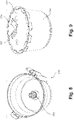
- FIGS. 7 and 8 the top and bottom of an outer vessel 210 is shown.
- the outer vessel 210 has an outer rotary coupler 212 at its center.
- the outer rotary coupler 212 is rotatable when the outer vessel 210 remains stationary. It has two parts.
- the outer rotary coupler 212 On the outside bottom of the outer vessel 210 ( FIG. 7 ), the outer rotary coupler 212 has a shape that is complementary to one of the motor couplings 112, 114, or 116.
- FIG. 7 On the outside bottom of the outer vessel 210 ( FIG. 7 ), the outer rotary coupler 212 has a shape that is complementary to one of the motor couplings 112, 114, or 116.
- FIG. 7 On the inside of the outer vessel 210 ( FIG. 7 ).
- the outer rotary coupler 212 has a shape that is complementary to the inner rotary coupler 232 of the inner vessel 230 so that the inner vessel 230 can engage with the outer vessel's rotary coupler 212.
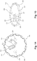
- FIGS. 14 and 15 show a top view and a bottom perspective view of a lid 220 that is adapted to be mounted on the food receiving vessel 230.
- the inner lid 220 On its surface, the inner lid 220 has a leading blade 222, which has a plurality of food passage openings 223 for food to pass through lid 220, and a trailing blade 224 that has a straight cutting edge and a straight food passage opening 225.
- the inner lid 220 also has two finger openings 226 for users to insert their finger so that the inner lid 220 can be lifted easily from the inner vessel 230. While a particular arrangement of a pair of blades is shown in FIG. 14 , those skilled in the art would understand that any other number, arrangements, and design of blades are also possible for the lid 220.
- the inner lid 220 When the inner lid 220 sits on top of the inner vessel 230, the inner lid 220 is secured in place with the inner vessel 230. As such, the inner lid 220 can move in unison with the inner vessel 230 during rotation but is stationary relative to the inner vessel 230. Those skilled in the art would understand that there are different ways to secure the inner lid 220 in place with the inner vessel 230.
- the inner vessel's circular wall 234 has a plurality of recesses 238 on the wall's top edge.
- the inner lid 220 has a plurality of protrusions 228 at its circumference.
- the protrusions 228 are complementary in shape and position with the recesses 238 so that the inner lid 220 can be secured in place with the inner vessel 230 by a mating of the recesses and the protrusions.
- the inner lid 220 is pivotally mounted on the inner vessel 230 so that the inner lid 220 is secured in place with the inner vessel 230 by a hinge.
- the rotation of the inner vessel 230 will carry the inner lid 220.
- the bottom of the center of the inner lid 220 may be largely planar and smooth and does not have a shaft extending downward from the lid 220.
- the cavity 235 of the inner vessel in between the center of the lid 220 and the center of the inner vessel 230 is shaft free. In other words, there is no shaft to connect the lid 220 and the inner vessel 230 at the center of the vessel.
- the arrangement that is free of a shaft provides significant advantage in making noodles or cutting foods, particularly vegetables, into strips.
- the food will reach and be processed by the inner lid 220.
- the lid 220 rotates counterclockwise so that the blade 222 is the leading blade and the blade 224 is the trailing blade.
- the food will first be processed by the leading blade 222 resulting in the food being cut into strips.
- the food cut into strips will be further processed when it is cut by the straight blade 224 to form individual strips. Since the blades are rotating, the processed strips have a tendency to settle into swirls in the food receiving vessel 230. If there was a central shaft present inside the vessel to rotate the lid 220, the strips would tend to settle around the shaft, creating friction about the rotating components thereby restricting the movement of the rotating components and sometimes sufficiently strangle the shaft to slow it down. This also adversely affects the quality of the noodles and strips, causing ripping and clumping of the same.
- the absence of a shaft significantly improves the operation of the invention and significantly increases the quality of the processed noodles or vegetable strips.
Landscapes
- Engineering & Computer Science (AREA)
- Mechanical Engineering (AREA)
- Food Science & Technology (AREA)
- Food-Manufacturing Devices (AREA)
- Details Of Cutting Devices (AREA)
- Noodles (AREA)
- Saccharide Compounds (AREA)
- Beans For Foods Or Fodder (AREA)
Claims (12)
- Dispositif de traitement alimentaire, comprenant :une base de moteur (110) comprenant un couplage de moteur (112) ;une cuve extérieure (210) étant fixée de façon amovible sur la base de moteur (110) ;une cuve intérieure (230) étant fixée de façon amovible à l'intérieur de la cuve extérieure (210) ;un couvercle intérieur (220) comprenant une lame (224) et une ouverture de passage de nourriture sur une surface du couvercle intérieur (220) ;caractérisé en ce quela cuve intérieure (230) a un système de couplage de cuve intérieure (232) destiné à engrener le couplage de moteur (112) et en ce que le couvercle intérieur (220) est fixé de façon sécurisée sur le dessus de la cuve intérieure (230) de sorte que la cuve intérieure (230) se déplace à l'unisson avec le couvercle intérieur (220) pendant la rotation.
- Dispositif de traitement alimentaire selon la revendication 1, dans lequel la base de moteur (110) comprend un second couplage de moteur (114) qui tourne à une vitesse différente du couplage de moteur (112) et dans lequel le second couplage de moteur (114) est conçu pour s'engrener de façon amovible avec une unité de traitement alimentaire différente.
- Dispositif de traitement alimentaire selon la revendication 1 ou 2, dans lequel la base de moteur (110) comprend en outre un actionneur de sécurité extérieur positionné au niveau d'un premier emplacement radial par rapport à un centre de la base de moteur (110) et un actionneur de sécurité intérieur (146) positionné au niveau d'un second emplacement radial par rapport à un centre de la base de moteur (110) ;
un circuit qui commande (111) la base de moteur (110) de sorte que le moteur (111) soit uniquement allumé lorsque soit l'actionneur de sécurité extérieur soit l'actionneur de sécurité intérieur (146) est enfoncé. - Dispositif de traitement alimentaire selon la revendication 2 ou l'alternative de la revendication 3, qui comprend la revendication 2, dans lequel la cuve extérieure (210) comprend un couvercle extérieur (250) qui est fixé de façon pivotante et une tige qui est positionnée à proximité de l'actionneur de sécurité extérieur lorsque la cuve extérieure (210) est fixée sur la base de moteur (110) ;la tige coulisse verticalement entre une position inférieure et une position supérieure, dans lequel lorsque le couvercle extérieur (250) est fermé, le couvercle extérieur (250) appuie sur la tige jusqu'à atteindre la position inférieure ; et à son tour, la tige enfonce l'actionneur de sécurité extérieur ; etl'unité de traitement alimentaire différente comprend une tige différente qui est positionnée de façon à s'engrener avec l'actionneur de sécurité intérieur (146) lorsque l'unité de traitement alimentaire différente est fixée sur la base de moteur (110) de sorte que la tige différente puisse enfoncer l'actionneur de sécurité intérieur (146).
- Dispositif de traitement alimentaire selon l'une quelconque des revendications précédentes, dans lequel le couvercle intérieur (220) est amovible depuis la cuve intérieure (230); la cuve intérieure (230) comprend une paroi circulaire ; la paroi circulaire ayant un bord supérieur qui comprend un renfoncement ; le couvercle intérieur (220) comprend une saillie qui est complémentaire au renfoncement de la cuve intérieure de sorte que le couvercle intérieur (220) soit maintenu en place de façon sécurisée avec la cuve intérieure par alignement du renfoncement et de la saillie.
- Dispositif de traitement alimentaire selon l'une quelconque des revendications précédentes, dans lequel le couvercle intérieur (220) est fixé de façon pivotante sur la cuve intérieure de sorte que le couvercle intérieur (220) soit maintenu en place de façon sécurisée avec la cuve intérieure par une charnière.
- Dispositif de traitement alimentaire selon l'une quelconque des revendications précédentes, dans lequel :la base de moteur (110) comprend un flasque ;la cuve extérieure (210) comprend une languette de retenue conçue pour glisser dans le flasque de façon à verrouiller en place la cuve extérieure (210) avec la base de moteur (110).
- Dispositif de traitement alimentaire selon l'une quelconque des revendications 1 à 3, dans lequel un couvercle extérieur (250) est fixé de façon pivotante sur la cuve extérieure (210) ;la base de moteur (110) comprend un actionneur de sécurité ;la cuve extérieure (210) comprend une tige qui coulisse verticalement entre une position inférieure et une position supérieure, dans lequel lorsque le couvercle extérieur (250) est fermé, le couvercle extérieur (250) pousse la tige en direction de la position inférieure ; et à son tour, la tige enfonce l'actionneur de sécurité.
- Dispositif de traitement alimentaire selon l'une quelconque des revendications précédentes, dans lequel la cuve extérieure (210) comprend un fond s'ouvrant de sorte que le système de couplage de la cuve intérieure (232) soit entraîné directement par le couplage de moteur (112).
- Dispositif de traitement alimentaire selon l'une quelconque des revendications 1 à 8, dans lequel la cuve extérieure (210) comprend un système de couplage rotatif de cuve extérieure (212) qui peut tourner, dans lequel le système de couplage rotatif de cuve extérieure (212) s'engrène de façon amovible avec le couplage de moteur (112) et dans lequel le système de couplage rotatif de cuve intérieure (232) s'engrène de façon amovible avec le système de couplage de cuve extérieure (212) de sorte que le système de couplage rotatif de cuve intérieure (232) soit entraîné indirectement par le couplage de moteur (112).
- Dispositif de traitement alimentaire selon l'une quelconque des revendications précédentes, dans lequel la lame (302) sur le couvercle intérieur (220) est unelame d'attaque (222) et dans lequel le couvercle intérieur (220) comprend une lame de fuite (224) ;la lame d'attaque (222) comprenant une pluralité de petites ouvertures pour faire des nouilles ;la lame de fuite (224) comprenant un bord tranchant droit.
- Dispositif de traitement alimentaire selon l'une quelconque des revendications précédentes, dans lequel le couvercle intérieur (220) comprend une pluralité d'ouvertures pour les doigts (226).
Priority Applications (2)
| Application Number | Priority Date | Filing Date | Title |
|---|---|---|---|
| RS20220614A RS63357B1 (sr) | 2016-03-23 | 2016-11-11 | Aparat za pripremanje hrane |
| HRP20220792TT HRP20220792T1 (hr) | 2016-03-23 | 2016-11-11 | Prerađivač hrane |
Applications Claiming Priority (2)
| Application Number | Priority Date | Filing Date | Title |
|---|---|---|---|
| US15/078,432 US10327595B2 (en) | 2016-03-23 | 2016-03-23 | Food processor |
| PCT/US2016/061683 WO2017164939A1 (fr) | 2016-03-23 | 2016-11-11 | Robot culinaire |
Publications (3)
| Publication Number | Publication Date |
|---|---|
| EP3270751A1 EP3270751A1 (fr) | 2018-01-24 |
| EP3270751A4 EP3270751A4 (fr) | 2018-10-10 |
| EP3270751B1 true EP3270751B1 (fr) | 2022-03-30 |
Family
ID=59896833
Family Applications (1)
| Application Number | Title | Priority Date | Filing Date |
|---|---|---|---|
| EP16895722.3A Active EP3270751B1 (fr) | 2016-03-23 | 2016-11-11 | Robot culinaire |
Country Status (23)
| Country | Link |
|---|---|
| US (2) | US10327595B2 (fr) |
| EP (1) | EP3270751B1 (fr) |
| JP (1) | JP6541192B2 (fr) |
| KR (1) | KR101942207B1 (fr) |
| CN (1) | CN107427157B (fr) |
| AU (1) | AU2016383698B2 (fr) |
| CA (1) | CA2971563C (fr) |
| DK (1) | DK3270751T3 (fr) |
| EA (1) | EA035841B1 (fr) |
| ES (1) | ES2922768T3 (fr) |
| GE (1) | GEP20197008B (fr) |
| HR (1) | HRP20220792T1 (fr) |
| HU (1) | HUE059103T2 (fr) |
| LT (1) | LT3270751T (fr) |
| MX (1) | MX2017008560A (fr) |
| NZ (1) | NZ733269A (fr) |
| PL (1) | PL3270751T3 (fr) |
| PT (1) | PT3270751T (fr) |
| RS (1) | RS63357B1 (fr) |
| SA (1) | SA517390015B1 (fr) |
| UA (1) | UA123766C2 (fr) |
| WO (1) | WO2017164939A1 (fr) |
| ZA (1) | ZA201706639B (fr) |
Families Citing this family (9)
| Publication number | Priority date | Publication date | Assignee | Title |
|---|---|---|---|---|
| CN104771092B (zh) * | 2015-04-03 | 2017-08-25 | 惠阳亚伦塑胶电器实业有限公司 | 一种搅拌机的装配刀座 |
| US10620035B2 (en) * | 2016-09-09 | 2020-04-14 | Capbran Holdings, Llc | Weighing device for comestible processors |
| EP3517001B1 (fr) * | 2018-01-26 | 2020-10-07 | BSH Hausgeräte GmbH | Appareil de cuisine comprenant un récipient muni d'un système de couplage |
| GB2590296A (en) * | 2018-08-02 | 2021-06-23 | Swidler Brant | Adapter between a disposable cup and a blender blade assembly |
| CN110089961B (zh) * | 2018-08-30 | 2024-02-06 | 江门市西屋厨房小家电有限公司 | 一种料理机锅体的安装结构 |
| CN109924903B (zh) * | 2018-11-28 | 2022-03-25 | 浙江绍兴苏泊尔生活电器有限公司 | 料理机 |
| CN113286540A (zh) * | 2019-04-10 | 2021-08-20 | 尚科宁家运营有限公司 | 食物加工系统 |
| CN110297448A (zh) * | 2019-06-25 | 2019-10-01 | 九阳股份有限公司 | 一种食品加工机 |
| US11344157B2 (en) * | 2020-05-08 | 2022-05-31 | Capbran Holdings, Llc | Blender and food processor combination with safety features |
Citations (1)
| Publication number | Priority date | Publication date | Assignee | Title |
|---|---|---|---|---|
| WO2017070214A1 (fr) * | 2015-10-20 | 2017-04-27 | Spectrum Brands, Inc. | Dispositif de coupe spiralé pour dispositif de transformation d'aliments |
Family Cites Families (69)
| Publication number | Priority date | Publication date | Assignee | Title |
|---|---|---|---|---|
| CH337126A (de) * | 1954-09-20 | 1959-03-15 | Gmbh Robert Bosch | Vorrichtung zum Entsaften von Früchten, Gemüsen und dergleichen |
| US3109949A (en) * | 1960-06-14 | 1963-11-05 | Licentia Gmbh | Drive unit for household and kitchen attachments |
| US3892365A (en) | 1971-07-23 | 1975-07-01 | Pierre Verdun | Apparatus for preparing food |
| US3985304A (en) | 1975-04-14 | 1976-10-12 | Sontheimer Carl Gustav | Rotary food processing apparatus |
| US4198887A (en) | 1978-02-02 | 1980-04-22 | Wilson Research & Development, Inc. | Julienne cutter tool |
| US4199112A (en) | 1978-10-25 | 1980-04-22 | General Electric Company | Processor and bidirectional cutting disc |
| US4194697A (en) | 1979-01-22 | 1980-03-25 | William Lembeck | Food processor and auxiliary mixing bowl therefor |
| JPS5924282Y2 (ja) * | 1979-07-10 | 1984-07-18 | 東芝テック株式会社 | 調理器の千切カツタ |
| US4387860A (en) * | 1980-11-03 | 1983-06-14 | Whirlpool Corporation | Food processor |
| DE3404348A1 (de) * | 1984-02-08 | 1985-08-08 | Robert Krups Stiftung & Co KG, 5650 Solingen | Kuechenmaschine mit motorischem antrieb |
| JPH0337564Y2 (fr) * | 1986-09-09 | 1991-08-08 | ||
| JPH01121534U (fr) * | 1988-02-08 | 1989-08-17 | ||
| FR2657518B1 (fr) | 1990-01-26 | 1993-12-03 | Moulinex | Appareils electromenager a fonctions multiples pour le traitement des aliments. |
| US5222430A (en) | 1992-08-19 | 1993-06-29 | Johnson Wang | Juicer/mixer device |
| US5380086A (en) | 1992-08-27 | 1995-01-10 | K-Tec, Inc. | Multipurpose food mixing appliance specially adapted for kneading dough |
| US5347205A (en) | 1992-09-11 | 1994-09-13 | Hamilton Beach/ Proctor-Silex, Inc. | Speed and mode control for a blender |
| US5405096A (en) | 1993-01-16 | 1995-04-11 | Seol; Yong-Seok | Multipurpose pulverizer |
| US5445332A (en) * | 1993-09-02 | 1995-08-29 | Kabushiki Kaisha Izumi Seiki Seisakusho | Food processor |
| US5392699A (en) | 1994-02-09 | 1995-02-28 | Tai; Chun-Ya L. | Vegetable and fruit juice processor and safety device thereof |
| US5421248A (en) | 1994-08-29 | 1995-06-06 | Airlux Electrical Co., Ltd. | Multi-food processor and juice extractor |
| US5537918A (en) | 1995-11-22 | 1996-07-23 | Patel; Chandulal F. | Juice extracting device |
| GB9722711D0 (en) * | 1997-10-29 | 1997-12-24 | Mcgill Shane R | Food blending apparatus |
| JPH11267045A (ja) * | 1998-03-19 | 1999-10-05 | Yoshiyuki Mori | 脱水及び他用途器 |
| US6050180A (en) | 1998-11-05 | 2000-04-18 | Omega Products, Inc. | Fruit and vegetable juicer |
| KR20000016250U (ko) * | 1999-01-28 | 2000-08-25 | 권태완 | 전기 후드믹서기 |
| US6632013B2 (en) | 2001-04-02 | 2003-10-14 | Sunbeam Products, Inc. | Blender with food processor capabilities |
| US6609821B2 (en) * | 2001-04-13 | 2003-08-26 | Sunbeam Products, Inc. | Blender base with food processor capabilities |
| US6402365B1 (en) | 2001-08-17 | 2002-06-11 | Kayue Electric Company Limited | Programmable electronic blender |
| US6397735B1 (en) | 2001-08-21 | 2002-06-04 | Kayue Electric Company Limited | Electronic food processor |
| FR2829679B1 (fr) | 2001-09-14 | 2004-07-30 | Santos Sa | Dispositif d'entrainement d'un outil rotatif pour appareil de traitement alimentaire, et appareil de traitement alimentaire pourvu d'un tel dispositif |
| US6814323B2 (en) | 2002-06-07 | 2004-11-09 | Hamilton Beach/Proctor-Silex, Inc. | Food processor |
| KR200295000Y1 (ko) | 2002-08-07 | 2002-11-13 | 변정은 | 탈수 겸용 믹서기 |
| US6776086B1 (en) * | 2003-04-25 | 2004-08-17 | Ken Ying Enterprise Co., Ltd. | Safety switch for a food processor |
| US6817750B1 (en) | 2003-08-26 | 2004-11-16 | Homeland Housewares, Llc | Individualized blender |
| US6971597B2 (en) | 2004-02-19 | 2005-12-06 | Hamilton Beach/Proctor-Silex, Inc. | Rotatable tray for food processor |
| US7530510B2 (en) | 2004-03-19 | 2009-05-12 | Hamilton Beach Brands, Inc. | Storage food processor |
| US20060011760A1 (en) | 2004-06-30 | 2006-01-19 | Maxwell Hsu | Mixer blade |
| US7340957B2 (en) | 2004-07-29 | 2008-03-11 | Los Alamos National Security, Llc | Ultrasonic analyte concentration and application in flow cytometry |
| JP2008529706A (ja) | 2005-02-21 | 2008-08-07 | コーニンクレッカ フィリップス エレクトロニクス エヌ ヴィ | フードプロセッサのためのすりおろしディスク |
| GB2426384B (en) * | 2005-05-17 | 2008-02-13 | Kenwood Marks Ltd | Interlock system |
| JP2007117444A (ja) | 2005-10-28 | 2007-05-17 | Izumi Products Co | 電動おろし調理器およびおろし金 |
| US7866259B2 (en) * | 2006-01-18 | 2011-01-11 | Innovative Products For Life Inc. | Centrifugal food degreaser |
| US7367519B2 (en) * | 2006-05-12 | 2008-05-06 | Dart Industries Inc. | Processing tool for foodstuffs |
| KR100755440B1 (ko) * | 2006-06-21 | 2007-09-05 | 김영기 | 착즙주스기 |
| CN101579196A (zh) | 2006-12-19 | 2009-11-18 | 康奈尔公司 | 改进的食物处理机 |
| US7950842B2 (en) | 2007-03-05 | 2011-05-31 | Hamilton Beach Brands, Inc. | Durability monitoring and improvement of a blender |
| US7581688B2 (en) | 2007-03-12 | 2009-09-01 | Whirlpool Corporation | Blender with crushed ice functionality |
| GB2454172A (en) * | 2007-10-29 | 2009-05-06 | Johnson Electric Sa | Motor assembly |
| US7600706B2 (en) * | 2008-01-24 | 2009-10-13 | Yuming Huang | Safety food grinder |
| EP2127578A1 (fr) * | 2008-05-30 | 2009-12-02 | Koninklijke Philips Electronics N.V. | Appareil de cuisine |
| US20100251906A1 (en) | 2009-04-02 | 2010-10-07 | Timothy Corcoran Repp | Salad spinner |
| EP2335535A1 (fr) | 2009-12-17 | 2011-06-22 | Koninklijke Philips Electronics N.V. | Râpe en forme de disque pour robot-mixeur |
| US20110154997A1 (en) | 2009-12-24 | 2011-06-30 | Jin Yi Huang | Juicer Structure |
| EP2547244B1 (fr) * | 2010-03-18 | 2016-09-07 | Breville PTY Limited | Presse-fruits combiné à un mixeur |
| CN101948728B (zh) * | 2010-09-10 | 2012-12-26 | 广东新宝电器股份有限公司 | 一种鸡尾酒机 |
| US8403556B2 (en) * | 2011-02-10 | 2013-03-26 | Quanzhou Yida Home Appliance Industry Co., Ltd. | Blender lid safety protection device |
| ES1075104Y (es) | 2011-06-21 | 2011-11-11 | Sammic Sl | Maquina combinada procesadora de alimentos |
| JP2013146330A (ja) * | 2012-01-18 | 2013-08-01 | Tiger Vacuum Bottle Co Ltd | 組立式攪拌型調理器 |
| US8833683B2 (en) * | 2012-03-08 | 2014-09-16 | Whirlpool Corporation | Food processor with external control for operating an adjustable cutting tool |
| KR101336733B1 (ko) * | 2012-04-19 | 2013-12-04 | (주)모닉스동양 | 탈수겸용 믹서기 |
| JP6019781B2 (ja) * | 2012-06-12 | 2016-11-02 | タイガー魔法瓶株式会社 | 回転式調理器 |
| CN202890392U (zh) | 2012-11-12 | 2013-04-24 | 漳州灿坤实业有限公司 | 一种食物处理机 |
| CN103960953A (zh) * | 2013-02-04 | 2014-08-06 | 亚弘电科技股份有限公司 | 榨汁机 |
| US9855535B2 (en) | 2013-03-01 | 2018-01-02 | Vita-Mix Management Corporation | Blending system |
| GB2516243B (en) * | 2013-07-16 | 2018-02-07 | Kenwood Ltd | Food mixers |
| US9458613B2 (en) * | 2013-10-28 | 2016-10-04 | Haier Us Appliance Solutions, Inc. | Waste disposal with improved housing configuration |
| CN203619410U (zh) * | 2013-11-28 | 2014-06-04 | 广东德豪润达电气股份有限公司 | 具有切丝/片功能的食物加工机 |
| CN203622518U (zh) * | 2013-11-28 | 2014-06-04 | 广东德豪润达电气股份有限公司 | 具有切丁功能的食物加工机 |
| US9049967B1 (en) | 2014-08-08 | 2015-06-09 | Euro-Pro Operating Llc | Food processing apparatus and method |
-
2016
- 2016-03-23 US US15/078,432 patent/US10327595B2/en active Active
- 2016-11-11 GE GEAP201614582A patent/GEP20197008B/en unknown
- 2016-11-11 KR KR1020177020368A patent/KR101942207B1/ko active IP Right Grant
- 2016-11-11 HU HUE16895722A patent/HUE059103T2/hu unknown
- 2016-11-11 EA EA201700358A patent/EA035841B1/ru unknown
- 2016-11-11 CN CN201680009455.7A patent/CN107427157B/zh active Active
- 2016-11-11 WO PCT/US2016/061683 patent/WO2017164939A1/fr active Application Filing
- 2016-11-11 LT LTEPPCT/US2016/061683T patent/LT3270751T/lt unknown
- 2016-11-11 AU AU2016383698A patent/AU2016383698B2/en active Active
- 2016-11-11 UA UAA201708453A patent/UA123766C2/uk unknown
- 2016-11-11 PL PL16895722.3T patent/PL3270751T3/pl unknown
- 2016-11-11 EP EP16895722.3A patent/EP3270751B1/fr active Active
- 2016-11-11 ES ES16895722T patent/ES2922768T3/es active Active
- 2016-11-11 JP JP2017538725A patent/JP6541192B2/ja active Active
- 2016-11-11 CA CA2971563A patent/CA2971563C/fr active Active
- 2016-11-11 HR HRP20220792TT patent/HRP20220792T1/hr unknown
- 2016-11-11 DK DK16895722.3T patent/DK3270751T3/da active
- 2016-11-11 RS RS20220614A patent/RS63357B1/sr unknown
- 2016-11-11 PT PT168957223T patent/PT3270751T/pt unknown
- 2016-11-11 MX MX2017008560A patent/MX2017008560A/es unknown
- 2016-11-11 NZ NZ733269A patent/NZ733269A/en unknown
-
2017
- 2017-09-24 SA SA517390015A patent/SA517390015B1/ar unknown
- 2017-10-03 ZA ZA2017/06639A patent/ZA201706639B/en unknown
- 2017-12-11 US US15/838,248 patent/US10512365B2/en active Active
Patent Citations (1)
| Publication number | Priority date | Publication date | Assignee | Title |
|---|---|---|---|---|
| WO2017070214A1 (fr) * | 2015-10-20 | 2017-04-27 | Spectrum Brands, Inc. | Dispositif de coupe spiralé pour dispositif de transformation d'aliments |
Also Published As
| Publication number | Publication date |
|---|---|
| US20180132666A1 (en) | 2018-05-17 |
| CA2971563C (fr) | 2019-01-08 |
| HUE059103T2 (hu) | 2022-10-28 |
| AU2016383698B2 (en) | 2018-04-19 |
| ZA201706639B (en) | 2019-01-30 |
| KR101942207B1 (ko) | 2019-01-24 |
| ES2922768T3 (es) | 2022-09-20 |
| CN107427157B (zh) | 2018-12-07 |
| RS63357B1 (sr) | 2022-07-29 |
| SA517390015B1 (ar) | 2020-06-30 |
| JP2018513700A (ja) | 2018-05-31 |
| EP3270751A1 (fr) | 2018-01-24 |
| EP3270751A4 (fr) | 2018-10-10 |
| EA201700358A1 (ru) | 2017-12-29 |
| PL3270751T3 (pl) | 2022-07-18 |
| WO2017164939A1 (fr) | 2017-09-28 |
| UA123766C2 (uk) | 2021-06-02 |
| DK3270751T3 (en) | 2022-07-04 |
| US10327595B2 (en) | 2019-06-25 |
| LT3270751T (lt) | 2022-07-11 |
| JP6541192B2 (ja) | 2019-07-10 |
| HRP20220792T1 (hr) | 2022-09-16 |
| MX2017008560A (es) | 2017-11-15 |
| US20170273510A1 (en) | 2017-09-28 |
| EA035841B1 (ru) | 2020-08-19 |
| AU2016383698A1 (en) | 2017-10-12 |
| CA2971563A1 (fr) | 2017-09-23 |
| CN107427157A (zh) | 2017-12-01 |
| NZ733269A (en) | 2018-06-29 |
| PT3270751T (pt) | 2022-07-05 |
| US10512365B2 (en) | 2019-12-24 |
| KR20170126442A (ko) | 2017-11-17 |
| GEP20197008B (en) | 2019-07-25 |
Similar Documents
| Publication | Publication Date | Title |
|---|---|---|
| EP3270751B1 (fr) | Robot culinaire | |
| US9433324B2 (en) | Kitchen appliance for processing foodstuff and method of operating same | |
| US4095751A (en) | Slicing and shredding apparatus | |
| US9049966B2 (en) | Food processor | |
| AU2011360093B2 (en) | Food processing device with control buttons mounted on lid | |
| CA3082176C (fr) | Accessoire de batteur spiraleur | |
| EP2741649B1 (fr) | Appareil pour traiter un aliment | |
| RU2693709C1 (ru) | Безопасная опорная конструкция и устройство для обработки пищи | |
| EP2958471B1 (fr) | Systèmes de robots culinaires | |
| KR20180119855A (ko) | 동력 전달 구조를 갖는 식품 가공 장치 | |
| CN108601484A (zh) | 用于食品加工器系统的切条机附件 |
Legal Events
| Date | Code | Title | Description |
|---|---|---|---|
| REG | Reference to a national code |
Ref country code: HR Ref legal event code: TUEP Ref document number: P20220792T Country of ref document: HR |
|
| STAA | Information on the status of an ep patent application or granted ep patent |
Free format text: STATUS: THE INTERNATIONAL PUBLICATION HAS BEEN MADE |
|
| PUAI | Public reference made under article 153(3) epc to a published international application that has entered the european phase |
Free format text: ORIGINAL CODE: 0009012 |
|
| STAA | Information on the status of an ep patent application or granted ep patent |
Free format text: STATUS: REQUEST FOR EXAMINATION WAS MADE |
|
| 17P | Request for examination filed |
Effective date: 20171017 |
|
| AK | Designated contracting states |
Kind code of ref document: A1 Designated state(s): AL AT BE BG CH CY CZ DE DK EE ES FI FR GB GR HR HU IE IS IT LI LT LU LV MC MK MT NL NO PL PT RO RS SE SI SK SM TR |
|
| AX | Request for extension of the european patent |
Extension state: BA ME |
|
| RIN1 | Information on inventor provided before grant (corrected) |
Inventor name: SAPIRE, COLIN |
|
| A4 | Supplementary search report drawn up and despatched |
Effective date: 20180907 |
|
| RIC1 | Information provided on ipc code assigned before grant |
Ipc: B02C 23/00 20060101ALI20180903BHEP Ipc: A47J 43/044 20060101ALI20180903BHEP Ipc: A47J 43/04 20060101AFI20180903BHEP Ipc: A47J 43/07 20060101ALI20180903BHEP Ipc: B01F 7/00 20060101ALI20180903BHEP Ipc: A47J 43/046 20060101ALI20180903BHEP Ipc: A47J 44/00 20060101ALI20180903BHEP |
|
| STAA | Information on the status of an ep patent application or granted ep patent |
Free format text: STATUS: EXAMINATION IS IN PROGRESS |
|
| DAV | Request for validation of the european patent (deleted) | ||
| DAX | Request for extension of the european patent (deleted) | ||
| 17Q | First examination report despatched |
Effective date: 20190618 |
|
| STAA | Information on the status of an ep patent application or granted ep patent |
Free format text: STATUS: EXAMINATION IS IN PROGRESS |
|
| GRAP | Despatch of communication of intention to grant a patent |
Free format text: ORIGINAL CODE: EPIDOSNIGR1 |
|
| STAA | Information on the status of an ep patent application or granted ep patent |
Free format text: STATUS: GRANT OF PATENT IS INTENDED |
|
| INTG | Intention to grant announced |
Effective date: 20211111 |
|
| GRAS | Grant fee paid |
Free format text: ORIGINAL CODE: EPIDOSNIGR3 |
|
| GRAJ | Information related to disapproval of communication of intention to grant by the applicant or resumption of examination proceedings by the epo deleted |
Free format text: ORIGINAL CODE: EPIDOSDIGR1 |
|
| GRAL | Information related to payment of fee for publishing/printing deleted |
Free format text: ORIGINAL CODE: EPIDOSDIGR3 |
|
| STAA | Information on the status of an ep patent application or granted ep patent |
Free format text: STATUS: EXAMINATION IS IN PROGRESS |
|
| INTC | Intention to grant announced (deleted) | ||
| GRAP | Despatch of communication of intention to grant a patent |
Free format text: ORIGINAL CODE: EPIDOSNIGR1 |
|
| RIC1 | Information provided on ipc code assigned before grant |
Ipc: A47J 43/06 20060101ALI20220111BHEP Ipc: A47J 44/00 20060101ALI20220111BHEP Ipc: A47J 43/07 20060101ALI20220111BHEP Ipc: A47J 43/044 20060101ALI20220111BHEP Ipc: A47J 43/04 20060101AFI20220111BHEP |
|
| STAA | Information on the status of an ep patent application or granted ep patent |
Free format text: STATUS: GRANT OF PATENT IS INTENDED |
|
| GRAA | (expected) grant |
Free format text: ORIGINAL CODE: 0009210 |
|
| STAA | Information on the status of an ep patent application or granted ep patent |
Free format text: STATUS: THE PATENT HAS BEEN GRANTED |
|
| INTG | Intention to grant announced |
Effective date: 20220217 |
|
| AK | Designated contracting states |
Kind code of ref document: B1 Designated state(s): AL AT BE BG CH CY CZ DE DK EE ES FI FR GB GR HR HU IE IS IT LI LT LU LV MC MK MT NL NO PL PT RO RS SE SI SK SM TR |
|
| REG | Reference to a national code |
Ref country code: GB Ref legal event code: FG4D |
|
| REG | Reference to a national code |
Ref country code: CH Ref legal event code: EP |
|
| REG | Reference to a national code |
Ref country code: AT Ref legal event code: REF Ref document number: 1478422 Country of ref document: AT Kind code of ref document: T Effective date: 20220415 |
|
| REG | Reference to a national code |
Ref country code: DE Ref legal event code: R096 Ref document number: 602016070637 Country of ref document: DE |
|
| REG | Reference to a national code |
Ref country code: IE Ref legal event code: FG4D |
|
| REG | Reference to a national code |
Ref country code: RO Ref legal event code: EPE |
|
| REG | Reference to a national code |
Ref country code: DK Ref legal event code: T3 Effective date: 20220630 |
|
| REG | Reference to a national code |
Ref country code: PT Ref legal event code: SC4A Ref document number: 3270751 Country of ref document: PT Date of ref document: 20220705 Kind code of ref document: T Free format text: AVAILABILITY OF NATIONAL TRANSLATION Effective date: 20220629 Ref country code: FI Ref legal event code: FGE |
|
| REG | Reference to a national code |
Ref country code: NL Ref legal event code: FP |
|
| REG | Reference to a national code |
Ref country code: SE Ref legal event code: TRGR |
|
| REG | Reference to a national code |
Ref country code: EE Ref legal event code: FG4A Ref document number: E022376 Country of ref document: EE Effective date: 20220628 |
|
| REG | Reference to a national code |
Ref country code: GR Ref legal event code: EP Ref document number: 20220401351 Country of ref document: GR Effective date: 20220808 |
|
| REG | Reference to a national code |
Ref country code: NO Ref legal event code: T2 Effective date: 20220330 |
|
| REG | Reference to a national code |
Ref country code: HR Ref legal event code: T1PR Ref document number: P20220792 Country of ref document: HR |
|
| REG | Reference to a national code |
Ref country code: ES Ref legal event code: FG2A Ref document number: 2922768 Country of ref document: ES Kind code of ref document: T3 Effective date: 20220920 |
|
| REG | Reference to a national code |
Ref country code: SK Ref legal event code: T3 Ref document number: E 40086 Country of ref document: SK |
|
| REG | Reference to a national code |
Ref country code: HU Ref legal event code: AG4A Ref document number: E059103 Country of ref document: HU |
|
| PG25 | Lapsed in a contracting state [announced via postgrant information from national office to epo] |
Ref country code: SM Free format text: LAPSE BECAUSE OF FAILURE TO SUBMIT A TRANSLATION OF THE DESCRIPTION OR TO PAY THE FEE WITHIN THE PRESCRIBED TIME-LIMIT Effective date: 20220330 |
|
| REG | Reference to a national code |
Ref country code: HR Ref legal event code: ODRP Ref document number: P20220792 Country of ref document: HR Payment date: 20221103 Year of fee payment: 7 |
|
| PG25 | Lapsed in a contracting state [announced via postgrant information from national office to epo] |
Ref country code: AL Free format text: LAPSE BECAUSE OF FAILURE TO SUBMIT A TRANSLATION OF THE DESCRIPTION OR TO PAY THE FEE WITHIN THE PRESCRIBED TIME-LIMIT Effective date: 20220330 |
|
| REG | Reference to a national code |
Ref country code: DE Ref legal event code: R097 Ref document number: 602016070637 Country of ref document: DE |
|
| PLBE | No opposition filed within time limit |
Free format text: ORIGINAL CODE: 0009261 |
|
| STAA | Information on the status of an ep patent application or granted ep patent |
Free format text: STATUS: NO OPPOSITION FILED WITHIN TIME LIMIT |
|
| 26N | No opposition filed |
Effective date: 20230103 |
|
| PG25 | Lapsed in a contracting state [announced via postgrant information from national office to epo] |
Ref country code: SI Free format text: LAPSE BECAUSE OF FAILURE TO SUBMIT A TRANSLATION OF THE DESCRIPTION OR TO PAY THE FEE WITHIN THE PRESCRIBED TIME-LIMIT Effective date: 20220330 |
|
| PG25 | Lapsed in a contracting state [announced via postgrant information from national office to epo] |
Ref country code: MC Free format text: LAPSE BECAUSE OF FAILURE TO SUBMIT A TRANSLATION OF THE DESCRIPTION OR TO PAY THE FEE WITHIN THE PRESCRIBED TIME-LIMIT Effective date: 20220330 |
|
| PGFP | Annual fee paid to national office [announced via postgrant information from national office to epo] |
Ref country code: AL Payment date: 20221124 Year of fee payment: 7 |
|
| REG | Reference to a national code |
Ref country code: HR Ref legal event code: ODRP Ref document number: P20220792 Country of ref document: HR Payment date: 20231019 Year of fee payment: 8 |
|
| PGFP | Annual fee paid to national office [announced via postgrant information from national office to epo] |
Ref country code: NL Payment date: 20231126 Year of fee payment: 8 Ref country code: LU Payment date: 20231127 Year of fee payment: 8 |
|
| PGFP | Annual fee paid to national office [announced via postgrant information from national office to epo] |
Ref country code: SK Payment date: 20231018 Year of fee payment: 8 |
|
| PGFP | Annual fee paid to national office [announced via postgrant information from national office to epo] |
Ref country code: GB Payment date: 20231127 Year of fee payment: 8 Ref country code: GR Payment date: 20231129 Year of fee payment: 8 |
|
| PGFP | Annual fee paid to national office [announced via postgrant information from national office to epo] |
Ref country code: ES Payment date: 20231201 Year of fee payment: 8 |
|
| PGFP | Annual fee paid to national office [announced via postgrant information from national office to epo] |
Ref country code: IS Payment date: 20231106 Year of fee payment: 8 |
|
| PGFP | Annual fee paid to national office [announced via postgrant information from national office to epo] |
Ref country code: TR Payment date: 20231026 Year of fee payment: 8 Ref country code: SE Payment date: 20231127 Year of fee payment: 8 Ref country code: RS Payment date: 20231020 Year of fee payment: 8 Ref country code: RO Payment date: 20231031 Year of fee payment: 8 Ref country code: PT Payment date: 20231024 Year of fee payment: 8 Ref country code: NO Payment date: 20231129 Year of fee payment: 8 Ref country code: LV Payment date: 20231024 Year of fee payment: 8 Ref country code: LT Payment date: 20231018 Year of fee payment: 8 Ref country code: IT Payment date: 20231122 Year of fee payment: 8 Ref country code: IE Payment date: 20231127 Year of fee payment: 8 Ref country code: HU Payment date: 20231031 Year of fee payment: 8 Ref country code: HR Payment date: 20231019 Year of fee payment: 8 Ref country code: FR Payment date: 20231127 Year of fee payment: 8 Ref country code: FI Payment date: 20231127 Year of fee payment: 8 Ref country code: EE Payment date: 20231023 Year of fee payment: 8 Ref country code: DK Payment date: 20231127 Year of fee payment: 8 Ref country code: DE Payment date: 20231129 Year of fee payment: 8 Ref country code: CZ Payment date: 20231024 Year of fee payment: 8 Ref country code: CH Payment date: 20231201 Year of fee payment: 8 Ref country code: BG Payment date: 20231121 Year of fee payment: 8 Ref country code: AT Payment date: 20231019 Year of fee payment: 8 |
|
| REG | Reference to a national code |
Ref country code: AT Ref legal event code: UEP Ref document number: 1478422 Country of ref document: AT Kind code of ref document: T Effective date: 20220330 |
|
| PGFP | Annual fee paid to national office [announced via postgrant information from national office to epo] |
Ref country code: PL Payment date: 20231019 Year of fee payment: 8 Ref country code: BE Payment date: 20231127 Year of fee payment: 8 |
|
| PG25 | Lapsed in a contracting state [announced via postgrant information from national office to epo] |
Ref country code: CY Free format text: LAPSE BECAUSE OF FAILURE TO SUBMIT A TRANSLATION OF THE DESCRIPTION OR TO PAY THE FEE WITHIN THE PRESCRIBED TIME-LIMIT Effective date: 20220330 |