EP3252015B1 - Plattenförmige ferritteilchen für pigment mit metallischem glanz - Google Patents
Plattenförmige ferritteilchen für pigment mit metallischem glanz Download PDFInfo
- Publication number
- EP3252015B1 EP3252015B1 EP16743223.6A EP16743223A EP3252015B1 EP 3252015 B1 EP3252015 B1 EP 3252015B1 EP 16743223 A EP16743223 A EP 16743223A EP 3252015 B1 EP3252015 B1 EP 3252015B1
- Authority
- EP
- European Patent Office
- Prior art keywords
- ferrite
- plate shaped
- ferrite particles
- resin molded
- electromagnetic wave
- Prior art date
- Legal status (The legal status is an assumption and is not a legal conclusion. Google has not performed a legal analysis and makes no representation as to the accuracy of the status listed.)
- Active
Links
- 229910000859 α-Fe Inorganic materials 0.000 title claims description 129
- 239000002245 particle Substances 0.000 title claims description 97
- 239000000049 pigment Substances 0.000 title claims description 20
- VQLYBLABXAHUDN-UHFFFAOYSA-N bis(4-fluorophenyl)-methyl-(1,2,4-triazol-1-ylmethyl)silane;methyl n-(1h-benzimidazol-2-yl)carbamate Chemical compound C1=CC=C2NC(NC(=O)OC)=NC2=C1.C=1C=C(F)C=CC=1[Si](C=1C=CC(F)=CC=1)(C)CN1C=NC=N1 VQLYBLABXAHUDN-UHFFFAOYSA-N 0.000 title 1
- 239000000463 material Substances 0.000 claims description 64
- 229920005989 resin Polymers 0.000 claims description 56
- 239000011347 resin Substances 0.000 claims description 56
- 239000002932 luster Substances 0.000 claims description 21
- 230000003746 surface roughness Effects 0.000 claims description 13
- 238000010304 firing Methods 0.000 description 31
- 238000004519 manufacturing process Methods 0.000 description 24
- 239000000843 powder Substances 0.000 description 18
- 230000035699 permeability Effects 0.000 description 16
- 238000000576 coating method Methods 0.000 description 15
- ZWEHNKRNPOVVGH-UHFFFAOYSA-N 2-Butanone Chemical compound CCC(C)=O ZWEHNKRNPOVVGH-UHFFFAOYSA-N 0.000 description 13
- 239000011230 binding agent Substances 0.000 description 13
- 239000011248 coating agent Substances 0.000 description 13
- 230000000052 comparative effect Effects 0.000 description 13
- 239000000203 mixture Substances 0.000 description 12
- 239000012298 atmosphere Substances 0.000 description 11
- 238000010298 pulverizing process Methods 0.000 description 10
- 238000000034 method Methods 0.000 description 8
- 239000007787 solid Substances 0.000 description 8
- 239000002994 raw material Substances 0.000 description 7
- XLOMVQKBTHCTTD-UHFFFAOYSA-N Zinc monoxide Chemical compound [Zn]=O XLOMVQKBTHCTTD-UHFFFAOYSA-N 0.000 description 6
- 239000008187 granular material Substances 0.000 description 6
- XLYOFNOQVPJJNP-UHFFFAOYSA-N water Substances O XLYOFNOQVPJJNP-UHFFFAOYSA-N 0.000 description 6
- 238000005266 casting Methods 0.000 description 5
- 238000002844 melting Methods 0.000 description 5
- 230000008018 melting Effects 0.000 description 5
- 239000011342 resin composition Substances 0.000 description 5
- 229920002799 BoPET Polymers 0.000 description 4
- UQSXHKLRYXJYBZ-UHFFFAOYSA-N Iron oxide Chemical compound [Fe]=O UQSXHKLRYXJYBZ-UHFFFAOYSA-N 0.000 description 4
- 239000012790 adhesive layer Substances 0.000 description 4
- 239000002131 composite material Substances 0.000 description 4
- 239000007788 liquid Substances 0.000 description 4
- 230000005415 magnetization Effects 0.000 description 4
- 239000002184 metal Substances 0.000 description 4
- 229910052751 metal Inorganic materials 0.000 description 4
- 239000002243 precursor Substances 0.000 description 4
- 238000002360 preparation method Methods 0.000 description 4
- 238000012545 processing Methods 0.000 description 4
- QPLDLSVMHZLSFG-UHFFFAOYSA-N Copper oxide Chemical compound [Cu]=O QPLDLSVMHZLSFG-UHFFFAOYSA-N 0.000 description 3
- 239000011358 absorbing material Substances 0.000 description 3
- 230000001413 cellular effect Effects 0.000 description 3
- 230000002209 hydrophobic effect Effects 0.000 description 3
- 239000010410 layer Substances 0.000 description 3
- 238000002156 mixing Methods 0.000 description 3
- 238000000465 moulding Methods 0.000 description 3
- 239000011241 protective layer Substances 0.000 description 3
- 239000011787 zinc oxide Substances 0.000 description 3
- 239000007864 aqueous solution Substances 0.000 description 2
- 238000001354 calcination Methods 0.000 description 2
- 238000001723 curing Methods 0.000 description 2
- 239000002270 dispersing agent Substances 0.000 description 2
- 230000000694 effects Effects 0.000 description 2
- 239000000945 filler Substances 0.000 description 2
- 239000011521 glass Substances 0.000 description 2
- 238000010438 heat treatment Methods 0.000 description 2
- XEEYBQQBJWHFJM-UHFFFAOYSA-N iron Substances [Fe] XEEYBQQBJWHFJM-UHFFFAOYSA-N 0.000 description 2
- JEIPFZHSYJVQDO-UHFFFAOYSA-N iron(III) oxide Inorganic materials O=[Fe]O[Fe]=O JEIPFZHSYJVQDO-UHFFFAOYSA-N 0.000 description 2
- 229910044991 metal oxide Inorganic materials 0.000 description 2
- 150000004706 metal oxides Chemical class 0.000 description 2
- 239000003960 organic solvent Substances 0.000 description 2
- 239000002002 slurry Substances 0.000 description 2
- 239000002904 solvent Substances 0.000 description 2
- 238000003756 stirring Methods 0.000 description 2
- 238000010301 surface-oxidation reaction Methods 0.000 description 2
- 238000012546 transfer Methods 0.000 description 2
- BQCIDUSAKPWEOX-UHFFFAOYSA-N 1,1-Difluoroethene Chemical compound FC(F)=C BQCIDUSAKPWEOX-UHFFFAOYSA-N 0.000 description 1
- BVKZGUZCCUSVTD-UHFFFAOYSA-L Carbonate Chemical compound [O-]C([O-])=O BVKZGUZCCUSVTD-UHFFFAOYSA-L 0.000 description 1
- 239000005751 Copper oxide Substances 0.000 description 1
- 229920006370 Kynar Polymers 0.000 description 1
- 229920000877 Melamine resin Polymers 0.000 description 1
- 239000004640 Melamine resin Substances 0.000 description 1
- 239000002033 PVDF binder Substances 0.000 description 1
- VYPSYNLAJGMNEJ-UHFFFAOYSA-N Silicium dioxide Chemical compound O=[Si]=O VYPSYNLAJGMNEJ-UHFFFAOYSA-N 0.000 description 1
- 229920001807 Urea-formaldehyde Polymers 0.000 description 1
- 229910001308 Zinc ferrite Inorganic materials 0.000 description 1
- 239000000654 additive Substances 0.000 description 1
- 239000011324 bead Substances 0.000 description 1
- 239000003795 chemical substances by application Substances 0.000 description 1
- 238000004891 communication Methods 0.000 description 1
- 238000009833 condensation Methods 0.000 description 1
- 230000005494 condensation Effects 0.000 description 1
- 238000001816 cooling Methods 0.000 description 1
- 239000010949 copper Substances 0.000 description 1
- 229910000431 copper oxide Inorganic materials 0.000 description 1
- 238000013461 design Methods 0.000 description 1
- 239000003814 drug Substances 0.000 description 1
- 238000005516 engineering process Methods 0.000 description 1
- 239000003822 epoxy resin Substances 0.000 description 1
- 230000003760 hair shine Effects 0.000 description 1
- 238000013007 heat curing Methods 0.000 description 1
- 238000009413 insulation Methods 0.000 description 1
- 238000011835 investigation Methods 0.000 description 1
- 230000001788 irregular Effects 0.000 description 1
- 239000000696 magnetic material Substances 0.000 description 1
- 239000006247 magnetic powder Substances 0.000 description 1
- 230000007257 malfunction Effects 0.000 description 1
- 239000011159 matrix material Substances 0.000 description 1
- 229910000000 metal hydroxide Inorganic materials 0.000 description 1
- 150000004692 metal hydroxides Chemical class 0.000 description 1
- 229910000480 nickel oxide Inorganic materials 0.000 description 1
- GNRSAWUEBMWBQH-UHFFFAOYSA-N oxonickel Chemical compound [Ni]=O GNRSAWUEBMWBQH-UHFFFAOYSA-N 0.000 description 1
- 239000008188 pellet Substances 0.000 description 1
- 230000002093 peripheral effect Effects 0.000 description 1
- 239000005011 phenolic resin Substances 0.000 description 1
- 238000005498 polishing Methods 0.000 description 1
- 229920000647 polyepoxide Polymers 0.000 description 1
- 229920002981 polyvinylidene fluoride Polymers 0.000 description 1
- UMPKMCDVBZFQOK-UHFFFAOYSA-N potassium;iron(3+);oxygen(2-) Chemical compound [O-2].[O-2].[K+].[Fe+3] UMPKMCDVBZFQOK-UHFFFAOYSA-N 0.000 description 1
- 238000003825 pressing Methods 0.000 description 1
- 238000002203 pretreatment Methods 0.000 description 1
- 238000010408 sweeping Methods 0.000 description 1
- 230000000007 visual effect Effects 0.000 description 1
- 239000011701 zinc Substances 0.000 description 1
- WGEATSXPYVGFCC-UHFFFAOYSA-N zinc ferrite Chemical compound O=[Zn].O=[Fe]O[Fe]=O WGEATSXPYVGFCC-UHFFFAOYSA-N 0.000 description 1
- 229910003145 α-Fe2O3 Inorganic materials 0.000 description 1
Images

Classifications
-
- C—CHEMISTRY; METALLURGY
- C09—DYES; PAINTS; POLISHES; NATURAL RESINS; ADHESIVES; COMPOSITIONS NOT OTHERWISE PROVIDED FOR; APPLICATIONS OF MATERIALS NOT OTHERWISE PROVIDED FOR
- C09D—COATING COMPOSITIONS, e.g. PAINTS, VARNISHES OR LACQUERS; FILLING PASTES; CHEMICAL PAINT OR INK REMOVERS; INKS; CORRECTING FLUIDS; WOODSTAINS; PASTES OR SOLIDS FOR COLOURING OR PRINTING; USE OF MATERIALS THEREFOR
- C09D7/00—Features of coating compositions, not provided for in group C09D5/00; Processes for incorporating ingredients in coating compositions
- C09D7/40—Additives
- C09D7/60—Additives non-macromolecular
- C09D7/61—Additives non-macromolecular inorganic
-
- C—CHEMISTRY; METALLURGY
- C09—DYES; PAINTS; POLISHES; NATURAL RESINS; ADHESIVES; COMPOSITIONS NOT OTHERWISE PROVIDED FOR; APPLICATIONS OF MATERIALS NOT OTHERWISE PROVIDED FOR
- C09C—TREATMENT OF INORGANIC MATERIALS, OTHER THAN FIBROUS FILLERS, TO ENHANCE THEIR PIGMENTING OR FILLING PROPERTIES ; PREPARATION OF CARBON BLACK ; PREPARATION OF INORGANIC MATERIALS WHICH ARE NO SINGLE CHEMICAL COMPOUNDS AND WHICH ARE MAINLY USED AS PIGMENTS OR FILLERS
- C09C1/00—Treatment of specific inorganic materials other than fibrous fillers; Preparation of carbon black
- C09C1/22—Compounds of iron
- C09C1/24—Oxides of iron
- C09C1/245—Oxides of iron of plate-like shape
-
- C—CHEMISTRY; METALLURGY
- C01—INORGANIC CHEMISTRY
- C01G—COMPOUNDS CONTAINING METALS NOT COVERED BY SUBCLASSES C01D OR C01F
- C01G49/00—Compounds of iron
-
- C—CHEMISTRY; METALLURGY
- C01—INORGANIC CHEMISTRY
- C01G—COMPOUNDS CONTAINING METALS NOT COVERED BY SUBCLASSES C01D OR C01F
- C01G49/00—Compounds of iron
- C01G49/02—Oxides; Hydroxides
- C01G49/06—Ferric oxide [Fe2O3]
-
- C—CHEMISTRY; METALLURGY
- C01—INORGANIC CHEMISTRY
- C01G—COMPOUNDS CONTAINING METALS NOT COVERED BY SUBCLASSES C01D OR C01F
- C01G53/00—Compounds of nickel
-
- C—CHEMISTRY; METALLURGY
- C08—ORGANIC MACROMOLECULAR COMPOUNDS; THEIR PREPARATION OR CHEMICAL WORKING-UP; COMPOSITIONS BASED THEREON
- C08K—Use of inorganic or non-macromolecular organic substances as compounding ingredients
- C08K3/00—Use of inorganic substances as compounding ingredients
- C08K3/18—Oxygen-containing compounds, e.g. metal carbonyls
- C08K3/20—Oxides; Hydroxides
- C08K3/22—Oxides; Hydroxides of metals
-
- C—CHEMISTRY; METALLURGY
- C09—DYES; PAINTS; POLISHES; NATURAL RESINS; ADHESIVES; COMPOSITIONS NOT OTHERWISE PROVIDED FOR; APPLICATIONS OF MATERIALS NOT OTHERWISE PROVIDED FOR
- C09C—TREATMENT OF INORGANIC MATERIALS, OTHER THAN FIBROUS FILLERS, TO ENHANCE THEIR PIGMENTING OR FILLING PROPERTIES ; PREPARATION OF CARBON BLACK ; PREPARATION OF INORGANIC MATERIALS WHICH ARE NO SINGLE CHEMICAL COMPOUNDS AND WHICH ARE MAINLY USED AS PIGMENTS OR FILLERS
- C09C1/00—Treatment of specific inorganic materials other than fibrous fillers; Preparation of carbon black
- C09C1/22—Compounds of iron
- C09C1/24—Oxides of iron
-
- C—CHEMISTRY; METALLURGY
- C09—DYES; PAINTS; POLISHES; NATURAL RESINS; ADHESIVES; COMPOSITIONS NOT OTHERWISE PROVIDED FOR; APPLICATIONS OF MATERIALS NOT OTHERWISE PROVIDED FOR
- C09D—COATING COMPOSITIONS, e.g. PAINTS, VARNISHES OR LACQUERS; FILLING PASTES; CHEMICAL PAINT OR INK REMOVERS; INKS; CORRECTING FLUIDS; WOODSTAINS; PASTES OR SOLIDS FOR COLOURING OR PRINTING; USE OF MATERIALS THEREFOR
- C09D5/00—Coating compositions, e.g. paints, varnishes or lacquers, characterised by their physical nature or the effects produced; Filling pastes
- C09D5/36—Pearl essence, e.g. coatings containing platelet-like pigments for pearl lustre
-
- C—CHEMISTRY; METALLURGY
- C09—DYES; PAINTS; POLISHES; NATURAL RESINS; ADHESIVES; COMPOSITIONS NOT OTHERWISE PROVIDED FOR; APPLICATIONS OF MATERIALS NOT OTHERWISE PROVIDED FOR
- C09D—COATING COMPOSITIONS, e.g. PAINTS, VARNISHES OR LACQUERS; FILLING PASTES; CHEMICAL PAINT OR INK REMOVERS; INKS; CORRECTING FLUIDS; WOODSTAINS; PASTES OR SOLIDS FOR COLOURING OR PRINTING; USE OF MATERIALS THEREFOR
- C09D7/00—Features of coating compositions, not provided for in group C09D5/00; Processes for incorporating ingredients in coating compositions
- C09D7/40—Additives
- C09D7/66—Additives characterised by particle size
- C09D7/69—Particle size larger than 1000 nm
-
- C—CHEMISTRY; METALLURGY
- C09—DYES; PAINTS; POLISHES; NATURAL RESINS; ADHESIVES; COMPOSITIONS NOT OTHERWISE PROVIDED FOR; APPLICATIONS OF MATERIALS NOT OTHERWISE PROVIDED FOR
- C09D—COATING COMPOSITIONS, e.g. PAINTS, VARNISHES OR LACQUERS; FILLING PASTES; CHEMICAL PAINT OR INK REMOVERS; INKS; CORRECTING FLUIDS; WOODSTAINS; PASTES OR SOLIDS FOR COLOURING OR PRINTING; USE OF MATERIALS THEREFOR
- C09D7/00—Features of coating compositions, not provided for in group C09D5/00; Processes for incorporating ingredients in coating compositions
- C09D7/40—Additives
- C09D7/70—Additives characterised by shape, e.g. fibres, flakes or microspheres
-
- H—ELECTRICITY
- H01—ELECTRIC ELEMENTS
- H01F—MAGNETS; INDUCTANCES; TRANSFORMERS; SELECTION OF MATERIALS FOR THEIR MAGNETIC PROPERTIES
- H01F1/00—Magnets or magnetic bodies characterised by the magnetic materials therefor; Selection of materials for their magnetic properties
- H01F1/01—Magnets or magnetic bodies characterised by the magnetic materials therefor; Selection of materials for their magnetic properties of inorganic materials
- H01F1/03—Magnets or magnetic bodies characterised by the magnetic materials therefor; Selection of materials for their magnetic properties of inorganic materials characterised by their coercivity
- H01F1/12—Magnets or magnetic bodies characterised by the magnetic materials therefor; Selection of materials for their magnetic properties of inorganic materials characterised by their coercivity of soft-magnetic materials
- H01F1/34—Magnets or magnetic bodies characterised by the magnetic materials therefor; Selection of materials for their magnetic properties of inorganic materials characterised by their coercivity of soft-magnetic materials non-metallic substances, e.g. ferrites
- H01F1/36—Magnets or magnetic bodies characterised by the magnetic materials therefor; Selection of materials for their magnetic properties of inorganic materials characterised by their coercivity of soft-magnetic materials non-metallic substances, e.g. ferrites in the form of particles
-
- H—ELECTRICITY
- H05—ELECTRIC TECHNIQUES NOT OTHERWISE PROVIDED FOR
- H05K—PRINTED CIRCUITS; CASINGS OR CONSTRUCTIONAL DETAILS OF ELECTRIC APPARATUS; MANUFACTURE OF ASSEMBLAGES OF ELECTRICAL COMPONENTS
- H05K9/00—Screening of apparatus or components against electric or magnetic fields
-
- H—ELECTRICITY
- H05—ELECTRIC TECHNIQUES NOT OTHERWISE PROVIDED FOR
- H05K—PRINTED CIRCUITS; CASINGS OR CONSTRUCTIONAL DETAILS OF ELECTRIC APPARATUS; MANUFACTURE OF ASSEMBLAGES OF ELECTRICAL COMPONENTS
- H05K9/00—Screening of apparatus or components against electric or magnetic fields
- H05K9/0007—Casings
- H05K9/002—Casings with localised screening
- H05K9/0022—Casings with localised screening of components mounted on printed circuit boards [PCB]
- H05K9/0024—Shield cases mounted on a PCB, e.g. cans or caps or conformal shields
- H05K9/0026—Shield cases mounted on a PCB, e.g. cans or caps or conformal shields integrally formed from metal sheet
-
- C—CHEMISTRY; METALLURGY
- C01—INORGANIC CHEMISTRY
- C01P—INDEXING SCHEME RELATING TO STRUCTURAL AND PHYSICAL ASPECTS OF SOLID INORGANIC COMPOUNDS
- C01P2004/00—Particle morphology
- C01P2004/20—Particle morphology extending in two dimensions, e.g. plate-like
-
- C—CHEMISTRY; METALLURGY
- C01—INORGANIC CHEMISTRY
- C01P—INDEXING SCHEME RELATING TO STRUCTURAL AND PHYSICAL ASPECTS OF SOLID INORGANIC COMPOUNDS
- C01P2004/00—Particle morphology
- C01P2004/54—Particles characterised by their aspect ratio, i.e. the ratio of sizes in the longest to the shortest dimension
-
- C—CHEMISTRY; METALLURGY
- C01—INORGANIC CHEMISTRY
- C01P—INDEXING SCHEME RELATING TO STRUCTURAL AND PHYSICAL ASPECTS OF SOLID INORGANIC COMPOUNDS
- C01P2006/00—Physical properties of inorganic compounds
- C01P2006/42—Magnetic properties
-
- C—CHEMISTRY; METALLURGY
- C08—ORGANIC MACROMOLECULAR COMPOUNDS; THEIR PREPARATION OR CHEMICAL WORKING-UP; COMPOSITIONS BASED THEREON
- C08K—Use of inorganic or non-macromolecular organic substances as compounding ingredients
- C08K3/00—Use of inorganic substances as compounding ingredients
- C08K3/18—Oxygen-containing compounds, e.g. metal carbonyls
- C08K3/20—Oxides; Hydroxides
- C08K3/22—Oxides; Hydroxides of metals
- C08K2003/2265—Oxides; Hydroxides of metals of iron
Definitions
- the present invention relates to plate shaped ferrite particles having a metallic luster for a pigment, and more particularly to plate shaped ferrite particles for a pigment having electromagnetic wave shielding ability and designability, a resin molded material containing the plate shaped ferrite particles for a pigment, and an electromagnetic wave shield housing for storing an electronic circuit manufactured by using the resin molded material.
- ferrite materials have been used as an electromagnetic wave absorbing material or electromagnetic shielding material because of a high magnetic permeability, and the electromagnetic wave absorbing property of the ferrite is that the electromagnetic wave absorbing region corresponds to the frequency region equal to or higher than the natural resonance frequency of the ferrite.
- ferrite has many effects on electromagnetic wave absorbing properties, and a plate shaped or flaky shaped ferrite fills the gap between the particles by orientation and reduces the leakage of electromagnetic waves.
- Patent Document 1 Japanese Patent Laid-Open No. 10-233309 discloses the flaky ferrite powder having the length in the longitudinal direction of 1 to 100 ⁇ m and the aspect ratio of 5 to 100 manufactured by pulverizing the soft magnetic ferrite prepared by casting.
- the manufacturing method includes the melting step of melting raw materials of the soft magnetic ferrite under the specified atmosphere, the casting step of casting the molten ferrite prepared in the melting step in the casting mold preheated under the specified atmosphere and then cooling the molten ferrite under specified conditions to manufacture the ingot of the soft magnetic ferrite, and the pulverizing step of pulverizing the ingot prepared in the casting step with pulverizing means.
- the flaky ferrite powder disclosed in Patent Document 1 improves the magnetic field shielding properties in a high-frequency region of 1000 MHz or more if contained in the sheet-shaped magnetic field shielding material because the ferrite powder is oriented in the direction along with the sheet surface.
- the manufacturing method may simplify the manufacturing process of the ferrite powder for the magnetic field shielding material in the sheet form because the manufacturing method makes manufacturing of the flaky ferrite powder easy by only pulverizing the ingot of ferrite cast under preset conditions without difficult operations such as pulverizing of the spherical powder, and the method has the great industrial value.
- Patent Document 2 Japanese Patent Laid-Open No. 2001-284118 discloses the ferrite powder containing flaky ferrite particles, and at least a part of the flaky ferrite particles have the maximum major diameter d in the range of 1 ⁇ m or more and 100 ⁇ m or less, and the ratio (d/t) between the maximum major diameter d and the thickness t in the range is 2.5 ⁇ (d/t).
- the manufacturing method including the steps of molding the sheet from a raw material of ferrite, firing the sheet to finish the ferrite, and pulverizing the sheet of the ferrite to manufacture ferrite particles containing flaky ferrite particles is described.
- Patent Document 2 discloses that ferrite particles suitable for manufacturing the composite magnetic molded product that has the high magnetic permeability, is excellent in noise absorbing properties in a high-frequency band and is high in insulation reliability can be manufactured, and the manufacturing method can easily and stably manufacture the ferrite particles.
- Patent Document 3 Japanese Patent Laid-Open 2000-252113 discloses the soft magnetic ferrite particle powder having the plate shape and the composition represented by Mg a Cu b Zn c Fe d O 4 (wherein 0.3 ⁇ a ⁇ 0.5, 0 ⁇ b ⁇ 0.2, 0.4 ⁇ c ⁇ 0.6, and 1.8 ⁇ d ⁇ 2.2), and the soft magnetic ferrite particle composite material made therefrom. Patent Document 3 also discloses that the soft magnetic ferrite particle composite material containing the soft magnetic ferrite particle powder mixed in the matrix has the high real part of the specific magnetic permeability in the low frequency range, absorbs electromagnetic waves in the wide band in the high frequency range, and is excellent in formability and high in flexibility.
- the soft magnetic ferrite particle powder disclosed in Patent Document 3 can be manufactured by using plate shaped ⁇ -Fe 2 O 3 as the source of Fe element and firing the raw materials of ferrite at the temperature of 1200°C or lower.
- Patent Document 4 Japanese Patent Laid-Open No. 2001-15312 discloses the manufacturing method of an electromagnetic wave absorbing magnetic paste including the steps of coating the liquid mixture of ferrite fine powder and a binder on the film to prepare the ferrite sheet, peeling the ferrite sheet from the film, pulverizing the ferrite sheet followed by firing to prepare the ferrite powder, and mixing the ferrite powder with the paste material.
- the manufacturing method disclosed in Patent Document 4 enables manufacturing of the electromagnetic wave absorbing magnetic paste containing ferrite particles having an aspect ratio of 10 or more, and the electromagnetic wave absorbing magnetic paste absorbs high-frequency electromagnetic waves in the wide band with the high absorptivity.
- the soft magnetic ferrite particle composite material disclosed in Patent Document 3 contains gray or black ferrite particle powder in the tile form and is just attached to the electronic circuit in the case of a cellular phone.
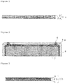
- Figures 3 and 4 show cross-sectional views of the resin molded material prepared by using the plate shaped ferrite and the cross-sectional view of the electromagnetic wave shield housing part for storing the electronic circuit with use of the resin molded material.
- Figure 3 shows the resin molded material 1b, the ferrite particles layer 2b, the protective layer 4, and the adhesive layer 5.
- the resin molded material 1b is the laminate of the protective layer 4, the ferrite particles layer 2b, and the adhesive layer 5.
- Figure 4 shows the antenna coil 6, the electronic circuit 7, the electromagnetic wave shield 8 manufactured by using metal, and the housing (case) 9 made of resin.
- the resin molded material 1b in Figure 4 is adhered to the electromagnetic wave shield manufactured by using metal 8 through the adhesive layer 5, and the housing (case) 9 made of the resin does not shield radio waves.
- the ferrite particles layer 2b constitutes the resin molded material 1b in the tile form together with the protective layer 4 and the adhesive layer 5, the resin molded material is just attached to the electronic circuit 7 in the housing (case) 9 made of resin in the cellular phone.
- Patent Document 5 relates to a specific process for the production of an anisometric yellow-brown zinc ferrite pigment.
- Patent Document 6 relates to a specific non-magnetic pigment comprising plate-like potassium ferrite particles.
- Patent Document 7 relates to specific flaky ferrite particles.
- Patent Document 8 relates to a specific lamellar pigment based on iron oxide.
- An object of the present invention is to provide a plate shaped ferrite particle for a pigment having both of electromagnetic wave shielding ability and designability, a resin molded material containing the plate shaped ferrite particles for a pigment, and an electromagnetic wave shield housing made of the resin molded material for storing an electronic circuit.
- the present inventors thought out the plate shaped ferrite particles having a metallic luster can achieve the object described above that have electromagnetic wave shielding ability and designability, and the present invention was accomplished.
- the present invention provides a plate shaped ferrite particle for a pigment characterized in having a metallic luster.
- the plate shaped ferrite particles for a pigment according to the present invention have a length in the minor axis direction of 3 to 100 ⁇ m, and a length in the major axis direction of 10 to 2000 ⁇ m.
- the surface roughness (Ra) thereof is 0.01 to 3 ⁇ m as measured with a laser microscope.
- the present invention also provides a resin molded material containing the plate shaped ferrite particles for a pigment.
- the present invention also provides an electromagnetic wave shield housing for storing an electronic circuit made of the resin molded material as well as the corresponding use.
- the plate shaped ferrite particles for a pigment according to the present invention have not only electromagnetic wave shielding ability but also designability because the plate shaped ferrite particles have a metallic luster. If the plate shaped ferrite particles are used for a pigment in preparation of the resin molded material, an electromagnetic wave shield housing for storing an electronic circuit can be manufactured by using the resin molded material. Since the ferrite particles are not in a tile form, the resin molded material prepared by using a resin has flexibility and the electromagnetic wave shield housing can be subjected to curving surface processing. Further, the electromagnetic wave shield housing has designability because the plate shaped ferrite particles have a metallic luster. The electromagnetic wave shield housing can be used for a long period because the ferrite as an oxide causes no surface oxidation.
- the plate shaped ferrite particles according to the present invention are used for a pigment because the plate shaped ferrite particles have a metallic luster.
- the term "ferrite particles” in the present invention refer to a mass of individual ferrite particles unless otherwise noted, and the simple term “particles" refer to individual ferrite particles.
- the metallic luster shows only for a ferrite particle's surface having a smooth surface with light reflecting in the incident direction, the surface shines in a white color. If light does not reflect in the incident direction, a ferrite particle shows a black color inherent to the ferrite composition.
- the smoothness of the ferrite particle's surface will be described later.
- the plate shaped ferrite particles according to the present invention have the length in the minor axis direction of 3 to 100 ⁇ m, and the length in the major axis direction of 10 to 2000 ⁇ m.
- the length in the minor axis direction is less than 3 ⁇ m, too thin ferrite particles crack due to the poor strength. If so, a sufficient metallic luster may not be achieved. If the length exceeds 100 ⁇ m, ferrite particles project from the curved surface and no resin molded material having a smooth curved surface may be achieved when a molding having a curved surface should be manufactured by using a resin composition containing ferrite particles. If the length in the major axis direction is less than 10 ⁇ m, incident light cannot be sufficiently reflected, and a metallic luster cannot be achieved. If the length exceeds 2000 ⁇ m, the particles may bond to each other by melting in final firing and the thickness in the minor axis direction tends to increase. As a result, a plate shaped particle having a desired thickness cannot be manufactured.
- the length of the major axis direction is determined as follows. Images of the particles are photographed with SEM at a magnification of 35, and the image is printed out on an A4-size paper for each visual field. The horizontal Feret diameter of a particle is examined with a ruler, and the arithmetic average of 100 particles is presumed as the average length in the major axis direction (average plate diameter).
- the length of the minor axis direction is determined after preparing the specimen for examination in the following method.
- the plate shaped ferrite particle according to the present invention has the surface roughness (Ra) measured with a laser microscope of 0.01 to 3 ⁇ m. If the surface roughness (Ra) is in the range, the plate shaped ferrite particle achieves the metallic luster.
- the surface roughness (Ra) measured with a laser microscope never be less than 0.01 ⁇ m due to the slight difference in the growth rate of grains in the final firing. If the surface roughness exceeds 3 ⁇ m, the incident light is reflected or absorbed in various directions due to the large roughness of the surface and no metallic luster is achieved.
- the examination is carried out in accordance with JIS B 0601-2001.
- the manufacturing method of the plate shaped ferrite particles according to the present invention includes preparing of a hydrophilic ink containing a filler in advance.
- the filler include a metal oxide, a metal carbonate, a metal hydroxide, and the mixture thereof.
- the raw materials of ferrite are mixed with a Henschel mixer and the like, and the mixture is then pelletized with a roller compacter.
- the pellets are then calcined at a firing temperature of 1000°C with a rotary kiln in the air atmosphere, for example.
- the calcined material prepared is roughly pulverized and then finely pulverized. Then, water content is adjusted to finish a calcined material in a cake form. To the calcined material in the cake form is added a dispersant and dispersed with a homogenizer to prepare the hydrophilic ink. Then, a binder is added to the hydrophilic ink.
- the ink finished is coated on a film with a comma coater to make the thickness of the coated ink in the specific range. After coating, and water contained is removed, and the whole including the film is immersed in a solvent such as methyl ethyl ketone to peel the ink. Then, the solvent is removed to prepare the plate shaped granulated material prepared before firing (ferrite precursor).
- a solvent such as methyl ethyl ketone
- the plate shaped granulated material prepared before firing (ferrite precursor) is subjected to binder removing followed by final firing.
- the fired product is then pulverized to manufacture the plate shaped ferrite particles in the specified form.
- Surface roughness of the hydrophobic base material is preferably 5 ⁇ m or less in manufacturing of the plate shaped ferrite particles to achieve a metallic luster. If the surface roughness exceeds 5 ⁇ m, the irregularities on the surface of a coated ink tend to be large, and no metallic luster is achieved.
- the solid content of the ink is preferably 50 to 87 wt%, more preferably 65 to 85 wt%. If the solid content is less than 50 wt%, the hydrophilic ink is repelled by the hydrophobic base material, and no ink is coated. As a result, no plate shaped granulated material is manufactured.
- the ink has poor spreadability because the viscosity of the ink is too high, and it may makes coating of the ink impossible.
- the viscosity of the ink is preferably 500 to 2500 cp. If the viscosity is less than 500 cp, the hydrophilic ink is repelled by the hydrophobic base material, and no ink is coated. As a result, no plate shaped granulated material is manufactured. If the viscosity exceeds 2500 cp, the ink has poor spreadability and it may makes coating of the ink impossible.
- the resin molded material according to the present composition is manufactured by heat curing the resin composition prepared by mixing the ferrite particles described above with a resin.
- the resin composition contains 50 to 99.5 wt% of the plate shaped ferrite particles described above. If the content of the ferrite particles is less than 50 wt%, the properties of ferrite cannot be sufficiently achieved even if the ferrite particles are contained. If the content of the ferrite particles exceeds 99.5 wt%, molding may be impossible because almost no resin is contained.
- the resin used in the resin composition preferably has flexibility. If the resin having flexibility is used, the curved surface is processed in the resin molded material.
- the resin include an epoxy resin, a phenol resin, a melamine resin, a urea resin and a fluorine-contained resin, and they are not specifically limited.
- the resin composition contains a curing agent, a curing accelerator, and various additives such as silica particles according to needs.
- the cross-sectional view of the resin molded material according to the present invention is shown in Figure 1 .
- the resin molded material 1a shown in Figure 1 includes plate shaped ferrite particles 2a and the resin 3.
- using of a resin having flexibility enables the curved surface processing in the resin molded material la.
- FIG. 2 The cross-sectional view of an electromagnetic wave shield housing for storing an electronic circuit manufactured by using the resin molded material according to the present invention is shown in Figure 2 , and the same symbols as in Figure 4 show the same.
- the resin molded material 1a having a curved surface is disposed on the outer peripheral surface of an electromagnetic wave shield housing 8 made of metal, and the electromagnetic wave shield housing (seal) is formed.
- Iron oxide, nickel oxide, zinc oxide, and copper oxide were weighed to adjust composition.
- Fe 2 O 3 49 mol, NiO: 15 mol, ZnO: 30 mol, and CuO: 6 mol were mixed with the Henschel mixer. Then, the mixture was pelletized with the roller compacter, and then calcined in a rotary kiln at a calcining temperature of 1000°C in the air atmosphere.
- the calcined material prepared was roughly pulverized with the rod mill and then finely pulverized with a wet bead mill. Then, the calcined material in the cake form was prepared by adjusting the water content in the calcined material. To the calcined material in the cake form was added the dispersant and they were dispersed with a homogenizer to prepare the hydrophilic ink. The binder (PVA) in the amount of 2 wt% relative to the water content of the hydrophilic ink was further added. Thus, a hydrophilic ink having a solid content of 80% by weight was obtained.
- the hydrophilic ink prepared was coated on the commercially available PET film (thickness: 50 ⁇ m) with the comma coater to make the wet thickness 12 ⁇ m. After finishing the coating, water content was removed and the whole including the PET film was immersed in MEK to peel off the ink. The MEK was then removed to prepare the plate shaped granulated material before firing (ferrite precursor).
- the plate shaped granulated material before firing (ferrite precursor) prepared was subjected to binder removing in the air at 650°C. Then final firing was carried out in the air atmosphere at 1220°C for 4 hours.
- the fired material prepared had the plate shape. Then, the fired material was pulverized to manufacture the plate shaped ferrite particles having the length in the minor axis direction of 9 ⁇ m and the length in the major axis direction of 352 ⁇ m.
- the plate shaped ferrite particles were prepared in the same manner as in Example 1, except that the solid content of the ink was 85 wt%.
- the plate shaped ferrite particles were prepared in the same manner as in Example 1, except that the solid content of the ink was 70 wt%.
- the plate shaped ferrite particles were prepared in the same manner as in Example 1, except that the firing temperature was 1165°C.
- the plate shaped ferrite particles were prepared in the same manner as in Example 1, except that the wet thickness in the coating was 38 ⁇ m.
- the plate shaped ferrite particles were prepared in the same manner as in Example 1, except that the wet thickness in the coating was 8 ⁇ m .
- the plate shaped ferrite particles were prepared in the same manner as in Example 1, except that the firing temperature was 1050°C.
- the plate shaped ferrite particles were prepared in the same manner as in Example 1, except that the firing temperature was 1310°C.
- Table 1 shows the molar ratio of the raw materials charged, the calcination conditions (firing temperature and firing atmosphere), the fine pulverization (slurry particle diameter) and the hydrophilic ink (solid content, binder content and viscosity) in Examples 1 to 6 and Comparative Examples 1 to 2.
- Table 2 shows the coating conditions (coating method, film traveling speed, film surface temperature, and liquid for peeling), the binder removing conditions (treatment temperature and heating atmosphere), and the final firing conditions (firing temperature and firing atmosphere).
- Table 3 shows the properties of the plate shaped ferrite particle (presence/absence of metallic luster, length in major axis direction, length in minor axis direction, aspect ratio, surface roughness measured with the laser microscope, BET specific surface area, magnetic permeability, and magnetic properties).
- the BET specific surface area, the magnetic permeability, and the magnetic properties in Table 3 are determined as follows. The other examination methods are as described above.
- the BET specific surface area was examined by the specific surface area analyzer (Macsorb HM model 1208 (manufactured by Mountech Co.)).
- the sample in the amount of about 5 to 7 grams was placed in the standard sample cell for the exclusive use in the specific surface area analyzer and was accurately weighed with an analytical balance, and the sample (ferrite particles) was set in an examination port to start the examination.
- the examination was carried out by the one-point method.
- BET specific surface area was automatically calculated by input of the weight of the sample.
- the sample in the amount of about 20 grams was separately taken onto the medicine wrapping paper and then degassed to -0.1 MPa with the vacuum dryer. After confirming that the degree of vacuum reached -0.1 MPa or less, the sample was heated at 200°C for 2 hours.
- the examination was carried out using the RF impedance/material analyzer E4991A manufactured by Agilent Technologies Inc., with an electrode for examining magnetic material 16454A.
- sample for examining complex magnetic permeability was prepared as follows. 9 grams of plate shaped ferrite particles for suppressing noise and 1 gram of the binder resin (Kynar 301F: polyvinylidene fluoride) were weighed and placed in the 50-cc glass bottle for stirring and mixing for 30 minutes with the ball mill at 100 rpm.
- the magnetic properties were examined by using the vibrating sample magnetometer (model: VSM-C7-10A (manufactured by Toei Industry Co., Ltd.)).
- the cell with the inner diameter of 5 mm and the height of 2 mm was filled with the sample to be examined (ferrite particle) and set in the apparatus.
- sweeping was carried out up to 5K ⁇ 1000/4 ⁇ A/m under applied magnetic field.
- the applied magnetic field was reduced to draw the hysteresis curve on the recording paper. Based on the hysteresis curve, the magnetization under the applied magnetic field of 5K ⁇ 1000/4 ⁇ A/m was determined.
- the residual magnetization and the coercive force were determined in the same manner.
- the plate shaped ferrite particles having the small surface roughness with the metallic luster are prepared in Examples 1 to 6.
- sufficient metallic luster is not achieved in Comparative Example 1 because the excessively low firing temperature made the grain growth insufficient, and increased the surface roughness.
- No plate shaped ferrite particle is prepared in Comparative Example 2 because the excessively high firing temperature make the ferrite particles bond to each other by melting.
- the magnetic permeabilities in Comparative Examples 1 and 2 are lower than that in Examples 1 to 6, and magnetic shielding effect in Comparative Examples 1 and 2 is poor.
- the mixture of 60 wt% of a binder rein (10 wt% PVA aqueous solution) and 40 wt% of the plate shaped ferrite particles prepared in Example 1 were mixed, dispersed, and coated on a PET film with the applicator (10 mil). The coated film was dried to remove water content and then peeled from the PET film to prepare the resin molded material. The resin molded material was confirmed to have the metallic luster and excellent designability.
- a plurality of resin molded materials prepared in Example 7 were stacked and put between beveled dies to manufacture the housing and then heated and pressed.
- the housing curved surface processed is confirmed to have the metallic luster and excellent designability.
- the plate shaped ferrite particle for a pigment according to the present invention has a metallic luster, not only electromagnetic wave shielding ability but also designability can be achieved.
- a resin molded material can be prepared by using the plate shaped ferrite particle for a pigment, and an electromagnetic wave shield housing for storing an electronic circuit can be manufactured by using the resin molded material.
- the resin molded material formed by using the ferrite particle is not in a tile form and a resin has flexibility
- the electromagnetic wave shield housing according to the present invention can be formed by curved surface processing, and also has designability. Furthermore, since the ferrite as oxide causes no surface oxidation, a stable state for a long period is assured.
Landscapes
- Chemical & Material Sciences (AREA)
- Organic Chemistry (AREA)
- Engineering & Computer Science (AREA)
- Life Sciences & Earth Sciences (AREA)
- Materials Engineering (AREA)
- Wood Science & Technology (AREA)
- Inorganic Chemistry (AREA)
- Microelectronics & Electronic Packaging (AREA)
- Dispersion Chemistry (AREA)
- Power Engineering (AREA)
- Nanotechnology (AREA)
- Health & Medical Sciences (AREA)
- Chemical Kinetics & Catalysis (AREA)
- Medicinal Chemistry (AREA)
- Polymers & Plastics (AREA)
- Hard Magnetic Materials (AREA)
- Soft Magnetic Materials (AREA)
- Shielding Devices Or Components To Electric Or Magnetic Fields (AREA)
- Compositions Of Macromolecular Compounds (AREA)
- Compounds Of Iron (AREA)
Claims (4)
- Ein plättchenförmiges Ferritteilchen für ein Pigment, dadurch gekennzeichnet, dass es einen metallischen Glanz aufweist, wobei das Ferritteilchen eine Länge in Richtung der Nebenachse von 3 bis 100 µm, eine Länge in Richtung der Hauptachse von 10 bis 2000 µm, und eine Oberflächenrauheit (Ra) von 0,01 bis 3 µm, wie mit einem Lasermikroskop gemessen, aufweist.
- Ein Harzformmaterial, enthaltend das plättchenförmige Ferritteilchen für ein Pigment nach Anspruch 1.
- Ein Gehäuse zum Abschirmen von elektromagnetischen Wellen zur Aufbewahrung eines elektronischen Schaltkreises, hergestellt aus dem Harzformmaterial nach Anspruch 2.
- Verwendung des Harzformmaterials nach Anspruch 2 in einem Gehäuse zum Abschirmen von elektromagnetischen Wellen zur Aufbewahrung eines elektronischen Schaltkreises.
Applications Claiming Priority (2)
| Application Number | Priority Date | Filing Date | Title |
|---|---|---|---|
| JP2015013782 | 2015-01-27 | ||
| PCT/JP2016/051717 WO2016121619A1 (ja) | 2015-01-27 | 2016-01-21 | 金属光沢を有する顔料用板状フェライト粒子 |
Publications (3)
| Publication Number | Publication Date |
|---|---|
| EP3252015A1 EP3252015A1 (de) | 2017-12-06 |
| EP3252015A4 EP3252015A4 (de) | 2018-09-19 |
| EP3252015B1 true EP3252015B1 (de) | 2020-08-12 |
Family
ID=56543233
Family Applications (1)
| Application Number | Title | Priority Date | Filing Date |
|---|---|---|---|
| EP16743223.6A Active EP3252015B1 (de) | 2015-01-27 | 2016-01-21 | Plattenförmige ferritteilchen für pigment mit metallischem glanz |
Country Status (7)
| Country | Link |
|---|---|
| US (1) | US20170349449A1 (de) |
| EP (1) | EP3252015B1 (de) |
| JP (1) | JP6736479B2 (de) |
| KR (1) | KR102228647B1 (de) |
| CN (1) | CN107207277B (de) |
| TW (1) | TWI716376B (de) |
| WO (1) | WO2016121619A1 (de) |
Families Citing this family (2)
| Publication number | Priority date | Publication date | Assignee | Title |
|---|---|---|---|---|
| WO2019159800A1 (ja) * | 2018-02-13 | 2019-08-22 | パウダーテック株式会社 | 複合粒子、粉末、樹脂組成物および成形体 |
| JP7371348B2 (ja) | 2019-05-20 | 2023-10-31 | 三菱電機株式会社 | 回路基板用バリア構造 |
Family Cites Families (16)
| Publication number | Priority date | Publication date | Assignee | Title |
|---|---|---|---|---|
| US4681367A (en) * | 1983-06-21 | 1987-07-21 | Timmers Richard E | Auxiliary seat |
| DE3409722A1 (de) * | 1984-03-16 | 1985-09-26 | Bayer Ag, 5090 Leverkusen | Verfahren zur herstellung von gelbbraunen zinkferritpigmenten |
| JPS6163531A (ja) * | 1984-09-04 | 1986-04-01 | Agency Of Ind Science & Technol | 酸化鉄顔料 |
| JPH0645462B2 (ja) * | 1985-06-25 | 1994-06-15 | 宇部興産株式会社 | バリウムフエライト粉末の製造法 |
| JPH0716261B2 (ja) * | 1986-06-25 | 1995-02-22 | 松下電器産業株式会社 | 無線選択呼出装置 |
| DE3636156A1 (de) * | 1986-10-24 | 1988-04-28 | Basf Ag | Plaettchenfoermige pigmente der allgemeinen formel mn(pfeil abwaerts)x(pfeil abwaerts)-al(pfeil abwaerts)y(pfeil abwaerts)fe(pfeil abwaerts)2(pfeil abwaerts)(pfeil abwaerts)-(pfeil abwaerts)(pfeil abwaerts)((pfeil abwaerts)(pfeil abwaerts)x(pfeil abwaerts)(pfeil abwaerts)+(pfeil abwaerts)(pfeil abwaerts)y(pfeil abwaerts)(pfeil abwaerts))(pfeil abwaerts)o(pfeil abwaerts)3(pfeil abwaerts) |
| US5009712A (en) * | 1988-12-23 | 1991-04-23 | Toda Kogyo Corp. | Non-magnetic pigments |
| US5900343A (en) * | 1996-08-06 | 1999-05-04 | Hitachi Metals, Ltd. | Ferrite carrier for electrophotographic development |
| JPH10233309A (ja) * | 1997-02-21 | 1998-09-02 | Daido Steel Co Ltd | 扁平フェライト粉末およびその製造方法 |
| US6157801A (en) * | 1998-06-11 | 2000-12-05 | Canon Kabushiki Kaisha | Magnetic particles for charging, charging member, charging device, process cartridge, and electrophotographic apparatus |
| JP4279393B2 (ja) | 1999-03-04 | 2009-06-17 | 戸田工業株式会社 | 板状の軟磁性フェライト粒子粉末及びこれを用いた軟磁性フェライト粒子複合体 |
| JP2001015312A (ja) | 1999-06-29 | 2001-01-19 | Sony Corp | 磁性電磁波吸収ペーストの製造方法及び磁性電磁波吸収ペーストならびに電子部品、プリント板 |
| JP2001284118A (ja) | 2000-03-31 | 2001-10-12 | Tdk Corp | フェライト粉及びフェライト粉製造方法 |
| JP3984833B2 (ja) * | 2001-01-16 | 2007-10-03 | キヤノン株式会社 | 現像剤担持体の再生方法 |
| JP5390756B2 (ja) * | 2007-08-02 | 2014-01-15 | 関東電化工業株式会社 | 薄片状Baフェライト微粒子の製造方法 |
| JP5567396B2 (ja) * | 2010-05-31 | 2014-08-06 | Dowaエレクトロニクス株式会社 | 磁気ブラシ帯電用のフェライト粒子及びその製造方法 |
-
2016
- 2016-01-21 CN CN201680004862.9A patent/CN107207277B/zh active Active
- 2016-01-21 EP EP16743223.6A patent/EP3252015B1/de active Active
- 2016-01-21 WO PCT/JP2016/051717 patent/WO2016121619A1/ja active Application Filing
- 2016-01-21 KR KR1020177018677A patent/KR102228647B1/ko active IP Right Grant
- 2016-01-21 JP JP2016571983A patent/JP6736479B2/ja active Active
- 2016-01-21 TW TW105101828A patent/TWI716376B/zh active
- 2016-01-21 US US15/541,408 patent/US20170349449A1/en not_active Abandoned
Non-Patent Citations (1)
| Title |
|---|
| None * |
Also Published As
| Publication number | Publication date |
|---|---|
| KR20170107986A (ko) | 2017-09-26 |
| TWI716376B (zh) | 2021-01-21 |
| CN107207277A (zh) | 2017-09-26 |
| JP6736479B2 (ja) | 2020-08-05 |
| TW201631053A (zh) | 2016-09-01 |
| EP3252015A4 (de) | 2018-09-19 |
| EP3252015A1 (de) | 2017-12-06 |
| JPWO2016121619A1 (ja) | 2017-11-02 |
| KR102228647B1 (ko) | 2021-03-15 |
| CN107207277B (zh) | 2020-09-04 |
| WO2016121619A1 (ja) | 2016-08-04 |
| US20170349449A1 (en) | 2017-12-07 |
Similar Documents
| Publication | Publication Date | Title |
|---|---|---|
| TWI567765B (zh) | Magnetic parts and metal powders for use therewith and methods of making the same | |
| TWI394177B (zh) | Flat soft magnetic material and manufacturing method thereof | |
| EP2980811B1 (de) | Kompositmagnetpulver zur geräuschunterdrückung | |
| EP3248942B1 (de) | Harzzusammensetzung enthaltend ein ferritpulver in form hexagonaler plättchen, verfahren zu deren herstellung und formgegenstand geformt aus der harzzusammensetzung | |
| EP3453680B1 (de) | Ferritpulver, harzzusammensetzung, elektromagnetisches abschirmmaterial, elektronisches schaltungssubstrat, elektronische schaltungskomponente und gehäuse für elektronische vorrichtung | |
| WO2019112002A1 (ja) | 複合磁性粉末、磁性樹脂組成物、磁性樹脂ペースト、磁性樹脂粉末、磁性樹脂スラリー、磁性樹脂シート、金属箔付磁性樹脂シート、磁性プリプレグ及びインダクタ部品 | |
| EP3252015B1 (de) | Plattenförmige ferritteilchen für pigment mit metallischem glanz | |
| TW201621932A (zh) | 軟磁性扁平粉末及其製造方法 | |
| EP3753904A1 (de) | Mn-ferritpulver, harzzusammensetzung, elektromagnetische wellen abschirmendes material, elektronisches material und elektronisches bauelement | |
| EP3252017B1 (de) | Magnetischer füllstoff | |
| KR102264959B1 (ko) | 고투자율의 이종복합자성시트 및 그의 제조방법 | |
| EP3251735A1 (de) | Ferritteilchen für filtermaterial mit aussenschalenstruktur | |
| EP3664106A1 (de) | Verbundteilchen, pulver, harzzusammensetzung und formkörper | |
| CN110323029B (zh) | 复合磁性体 | |
| JP6295489B2 (ja) | 板状粒子用造粒物の製造方法 | |
| JP2013205689A (ja) | フェライト粒子並びにそれを用いた電子写真現像用キャリア及び電子写真用現像剤 |
Legal Events
| Date | Code | Title | Description |
|---|---|---|---|
| STAA | Information on the status of an ep patent application or granted ep patent |
Free format text: STATUS: THE INTERNATIONAL PUBLICATION HAS BEEN MADE |
|
| PUAI | Public reference made under article 153(3) epc to a published international application that has entered the european phase |
Free format text: ORIGINAL CODE: 0009012 |
|
| STAA | Information on the status of an ep patent application or granted ep patent |
Free format text: STATUS: REQUEST FOR EXAMINATION WAS MADE |
|
| 17P | Request for examination filed |
Effective date: 20170828 |
|
| AK | Designated contracting states |
Kind code of ref document: A1 Designated state(s): AL AT BE BG CH CY CZ DE DK EE ES FI FR GB GR HR HU IE IS IT LI LT LU LV MC MK MT NL NO PL PT RO RS SE SI SK SM TR |
|
| AX | Request for extension of the european patent |
Extension state: BA ME |
|
| DAV | Request for validation of the european patent (deleted) | ||
| DAX | Request for extension of the european patent (deleted) | ||
| A4 | Supplementary search report drawn up and despatched |
Effective date: 20180820 |
|
| RIC1 | Information provided on ipc code assigned before grant |
Ipc: C09D 7/40 20180101ALI20180813BHEP Ipc: C09D 5/36 20060101ALI20180813BHEP Ipc: C01G 49/06 20060101ALI20180813BHEP Ipc: H05K 9/00 20060101ALI20180813BHEP Ipc: C01G 53/00 20060101ALI20180813BHEP Ipc: C09C 1/24 20060101ALI20180813BHEP Ipc: H01F 1/36 20060101ALI20180813BHEP Ipc: C01G 49/00 20060101AFI20180813BHEP |
|
| STAA | Information on the status of an ep patent application or granted ep patent |
Free format text: STATUS: EXAMINATION IS IN PROGRESS |
|
| 17Q | First examination report despatched |
Effective date: 20190628 |
|
| GRAP | Despatch of communication of intention to grant a patent |
Free format text: ORIGINAL CODE: EPIDOSNIGR1 |
|
| STAA | Information on the status of an ep patent application or granted ep patent |
Free format text: STATUS: GRANT OF PATENT IS INTENDED |
|
| INTG | Intention to grant announced |
Effective date: 20191119 |
|
| RIN1 | Information on inventor provided before grant (corrected) |
Inventor name: IGARASHI, TETSUYA Inventor name: AGA, KOJI |
|
| GRAS | Grant fee paid |
Free format text: ORIGINAL CODE: EPIDOSNIGR3 |
|
| GRAJ | Information related to disapproval of communication of intention to grant by the applicant or resumption of examination proceedings by the epo deleted |
Free format text: ORIGINAL CODE: EPIDOSDIGR1 |
|
| GRAL | Information related to payment of fee for publishing/printing deleted |
Free format text: ORIGINAL CODE: EPIDOSDIGR3 |
|
| STAA | Information on the status of an ep patent application or granted ep patent |
Free format text: STATUS: EXAMINATION IS IN PROGRESS |
|
| GRAP | Despatch of communication of intention to grant a patent |
Free format text: ORIGINAL CODE: EPIDOSNIGR1 |
|
| STAA | Information on the status of an ep patent application or granted ep patent |
Free format text: STATUS: GRANT OF PATENT IS INTENDED |
|
| INTC | Intention to grant announced (deleted) | ||
| INTG | Intention to grant announced |
Effective date: 20200415 |
|
| GRAS | Grant fee paid |
Free format text: ORIGINAL CODE: EPIDOSNIGR3 |
|
| GRAA | (expected) grant |
Free format text: ORIGINAL CODE: 0009210 |
|
| STAA | Information on the status of an ep patent application or granted ep patent |
Free format text: STATUS: THE PATENT HAS BEEN GRANTED |
|
| AK | Designated contracting states |
Kind code of ref document: B1 Designated state(s): AL AT BE BG CH CY CZ DE DK EE ES FI FR GB GR HR HU IE IS IT LI LT LU LV MC MK MT NL NO PL PT RO RS SE SI SK SM TR |
|
| REG | Reference to a national code |
Ref country code: CH Ref legal event code: EP |
|
| REG | Reference to a national code |
Ref country code: DE Ref legal event code: R096 Ref document number: 602016041852 Country of ref document: DE |
|
| REG | Reference to a national code |
Ref country code: IE Ref legal event code: FG4D |
|
| REG | Reference to a national code |
Ref country code: AT Ref legal event code: REF Ref document number: 1301392 Country of ref document: AT Kind code of ref document: T Effective date: 20200915 |
|
| REG | Reference to a national code |
Ref country code: LT Ref legal event code: MG4D |
|
| REG | Reference to a national code |
Ref country code: NL Ref legal event code: MP Effective date: 20200812 |
|
| PG25 | Lapsed in a contracting state [announced via postgrant information from national office to epo] |
Ref country code: HR Free format text: LAPSE BECAUSE OF FAILURE TO SUBMIT A TRANSLATION OF THE DESCRIPTION OR TO PAY THE FEE WITHIN THE PRESCRIBED TIME-LIMIT Effective date: 20200812 Ref country code: LT Free format text: LAPSE BECAUSE OF FAILURE TO SUBMIT A TRANSLATION OF THE DESCRIPTION OR TO PAY THE FEE WITHIN THE PRESCRIBED TIME-LIMIT Effective date: 20200812 Ref country code: FI Free format text: LAPSE BECAUSE OF FAILURE TO SUBMIT A TRANSLATION OF THE DESCRIPTION OR TO PAY THE FEE WITHIN THE PRESCRIBED TIME-LIMIT Effective date: 20200812 Ref country code: SE Free format text: LAPSE BECAUSE OF FAILURE TO SUBMIT A TRANSLATION OF THE DESCRIPTION OR TO PAY THE FEE WITHIN THE PRESCRIBED TIME-LIMIT Effective date: 20200812 Ref country code: BG Free format text: LAPSE BECAUSE OF FAILURE TO SUBMIT A TRANSLATION OF THE DESCRIPTION OR TO PAY THE FEE WITHIN THE PRESCRIBED TIME-LIMIT Effective date: 20201112 Ref country code: GR Free format text: LAPSE BECAUSE OF FAILURE TO SUBMIT A TRANSLATION OF THE DESCRIPTION OR TO PAY THE FEE WITHIN THE PRESCRIBED TIME-LIMIT Effective date: 20201113 Ref country code: NO Free format text: LAPSE BECAUSE OF FAILURE TO SUBMIT A TRANSLATION OF THE DESCRIPTION OR TO PAY THE FEE WITHIN THE PRESCRIBED TIME-LIMIT Effective date: 20201112 |
|
| REG | Reference to a national code |
Ref country code: AT Ref legal event code: MK05 Ref document number: 1301392 Country of ref document: AT Kind code of ref document: T Effective date: 20200812 |
|
| PG25 | Lapsed in a contracting state [announced via postgrant information from national office to epo] |
Ref country code: IS Free format text: LAPSE BECAUSE OF FAILURE TO SUBMIT A TRANSLATION OF THE DESCRIPTION OR TO PAY THE FEE WITHIN THE PRESCRIBED TIME-LIMIT Effective date: 20201212 Ref country code: NL Free format text: LAPSE BECAUSE OF FAILURE TO SUBMIT A TRANSLATION OF THE DESCRIPTION OR TO PAY THE FEE WITHIN THE PRESCRIBED TIME-LIMIT Effective date: 20200812 Ref country code: PL Free format text: LAPSE BECAUSE OF FAILURE TO SUBMIT A TRANSLATION OF THE DESCRIPTION OR TO PAY THE FEE WITHIN THE PRESCRIBED TIME-LIMIT Effective date: 20200812 Ref country code: LV Free format text: LAPSE BECAUSE OF FAILURE TO SUBMIT A TRANSLATION OF THE DESCRIPTION OR TO PAY THE FEE WITHIN THE PRESCRIBED TIME-LIMIT Effective date: 20200812 Ref country code: RS Free format text: LAPSE BECAUSE OF FAILURE TO SUBMIT A TRANSLATION OF THE DESCRIPTION OR TO PAY THE FEE WITHIN THE PRESCRIBED TIME-LIMIT Effective date: 20200812 |
|
| PG25 | Lapsed in a contracting state [announced via postgrant information from national office to epo] |
Ref country code: EE Free format text: LAPSE BECAUSE OF FAILURE TO SUBMIT A TRANSLATION OF THE DESCRIPTION OR TO PAY THE FEE WITHIN THE PRESCRIBED TIME-LIMIT Effective date: 20200812 Ref country code: DK Free format text: LAPSE BECAUSE OF FAILURE TO SUBMIT A TRANSLATION OF THE DESCRIPTION OR TO PAY THE FEE WITHIN THE PRESCRIBED TIME-LIMIT Effective date: 20200812 Ref country code: CZ Free format text: LAPSE BECAUSE OF FAILURE TO SUBMIT A TRANSLATION OF THE DESCRIPTION OR TO PAY THE FEE WITHIN THE PRESCRIBED TIME-LIMIT Effective date: 20200812 Ref country code: RO Free format text: LAPSE BECAUSE OF FAILURE TO SUBMIT A TRANSLATION OF THE DESCRIPTION OR TO PAY THE FEE WITHIN THE PRESCRIBED TIME-LIMIT Effective date: 20200812 Ref country code: SM Free format text: LAPSE BECAUSE OF FAILURE TO SUBMIT A TRANSLATION OF THE DESCRIPTION OR TO PAY THE FEE WITHIN THE PRESCRIBED TIME-LIMIT Effective date: 20200812 |
|
| REG | Reference to a national code |
Ref country code: DE Ref legal event code: R097 Ref document number: 602016041852 Country of ref document: DE |
|
| PG25 | Lapsed in a contracting state [announced via postgrant information from national office to epo] |
Ref country code: ES Free format text: LAPSE BECAUSE OF FAILURE TO SUBMIT A TRANSLATION OF THE DESCRIPTION OR TO PAY THE FEE WITHIN THE PRESCRIBED TIME-LIMIT Effective date: 20200812 Ref country code: AL Free format text: LAPSE BECAUSE OF FAILURE TO SUBMIT A TRANSLATION OF THE DESCRIPTION OR TO PAY THE FEE WITHIN THE PRESCRIBED TIME-LIMIT Effective date: 20200812 Ref country code: AT Free format text: LAPSE BECAUSE OF FAILURE TO SUBMIT A TRANSLATION OF THE DESCRIPTION OR TO PAY THE FEE WITHIN THE PRESCRIBED TIME-LIMIT Effective date: 20200812 |
|
| PLBE | No opposition filed within time limit |
Free format text: ORIGINAL CODE: 0009261 |
|
| STAA | Information on the status of an ep patent application or granted ep patent |
Free format text: STATUS: NO OPPOSITION FILED WITHIN TIME LIMIT |
|
| PG25 | Lapsed in a contracting state [announced via postgrant information from national office to epo] |
Ref country code: SK Free format text: LAPSE BECAUSE OF FAILURE TO SUBMIT A TRANSLATION OF THE DESCRIPTION OR TO PAY THE FEE WITHIN THE PRESCRIBED TIME-LIMIT Effective date: 20200812 |
|
| 26N | No opposition filed |
Effective date: 20210514 |
|
| PG25 | Lapsed in a contracting state [announced via postgrant information from national office to epo] |
Ref country code: IT Free format text: LAPSE BECAUSE OF FAILURE TO SUBMIT A TRANSLATION OF THE DESCRIPTION OR TO PAY THE FEE WITHIN THE PRESCRIBED TIME-LIMIT Effective date: 20200812 |
|
| PG25 | Lapsed in a contracting state [announced via postgrant information from national office to epo] |
Ref country code: SI Free format text: LAPSE BECAUSE OF FAILURE TO SUBMIT A TRANSLATION OF THE DESCRIPTION OR TO PAY THE FEE WITHIN THE PRESCRIBED TIME-LIMIT Effective date: 20200812 Ref country code: MC Free format text: LAPSE BECAUSE OF FAILURE TO SUBMIT A TRANSLATION OF THE DESCRIPTION OR TO PAY THE FEE WITHIN THE PRESCRIBED TIME-LIMIT Effective date: 20200812 |
|
| REG | Reference to a national code |
Ref country code: CH Ref legal event code: PL |
|
| GBPC | Gb: european patent ceased through non-payment of renewal fee |
Effective date: 20210121 |
|
| PG25 | Lapsed in a contracting state [announced via postgrant information from national office to epo] |
Ref country code: LU Free format text: LAPSE BECAUSE OF NON-PAYMENT OF DUE FEES Effective date: 20210121 |
|
| REG | Reference to a national code |
Ref country code: BE Ref legal event code: MM Effective date: 20210131 |
|
| PG25 | Lapsed in a contracting state [announced via postgrant information from national office to epo] |
Ref country code: FR Free format text: LAPSE BECAUSE OF NON-PAYMENT OF DUE FEES Effective date: 20210131 |
|
| PG25 | Lapsed in a contracting state [announced via postgrant information from national office to epo] |
Ref country code: CH Free format text: LAPSE BECAUSE OF NON-PAYMENT OF DUE FEES Effective date: 20210131 Ref country code: GB Free format text: LAPSE BECAUSE OF NON-PAYMENT OF DUE FEES Effective date: 20210121 Ref country code: LI Free format text: LAPSE BECAUSE OF NON-PAYMENT OF DUE FEES Effective date: 20210131 |
|
| PG25 | Lapsed in a contracting state [announced via postgrant information from national office to epo] |
Ref country code: IE Free format text: LAPSE BECAUSE OF NON-PAYMENT OF DUE FEES Effective date: 20210121 |
|
| PG25 | Lapsed in a contracting state [announced via postgrant information from national office to epo] |
Ref country code: IS Free format text: LAPSE BECAUSE OF FAILURE TO SUBMIT A TRANSLATION OF THE DESCRIPTION OR TO PAY THE FEE WITHIN THE PRESCRIBED TIME-LIMIT Effective date: 20201212 |
|
| PG25 | Lapsed in a contracting state [announced via postgrant information from national office to epo] |
Ref country code: BE Free format text: LAPSE BECAUSE OF NON-PAYMENT OF DUE FEES Effective date: 20210131 |
|
| PG25 | Lapsed in a contracting state [announced via postgrant information from national office to epo] |
Ref country code: PT Free format text: LAPSE BECAUSE OF FAILURE TO SUBMIT A TRANSLATION OF THE DESCRIPTION OR TO PAY THE FEE WITHIN THE PRESCRIBED TIME-LIMIT Effective date: 20201214 |
|
| P01 | Opt-out of the competence of the unified patent court (upc) registered |
Effective date: 20230428 |
|
| PG25 | Lapsed in a contracting state [announced via postgrant information from national office to epo] |
Ref country code: CY Free format text: LAPSE BECAUSE OF FAILURE TO SUBMIT A TRANSLATION OF THE DESCRIPTION OR TO PAY THE FEE WITHIN THE PRESCRIBED TIME-LIMIT Effective date: 20200812 |
|
| PG25 | Lapsed in a contracting state [announced via postgrant information from national office to epo] |
Ref country code: HU Free format text: LAPSE BECAUSE OF FAILURE TO SUBMIT A TRANSLATION OF THE DESCRIPTION OR TO PAY THE FEE WITHIN THE PRESCRIBED TIME-LIMIT; INVALID AB INITIO Effective date: 20160121 |
|
| PG25 | Lapsed in a contracting state [announced via postgrant information from national office to epo] |
Ref country code: MK Free format text: LAPSE BECAUSE OF FAILURE TO SUBMIT A TRANSLATION OF THE DESCRIPTION OR TO PAY THE FEE WITHIN THE PRESCRIBED TIME-LIMIT Effective date: 20200812 |
|
| PGFP | Annual fee paid to national office [announced via postgrant information from national office to epo] |
Ref country code: DE Payment date: 20231128 Year of fee payment: 9 |