EP3252017B1 - Magnetischer füllstoff - Google Patents
Magnetischer füllstoff Download PDFInfo
- Publication number
- EP3252017B1 EP3252017B1 EP16743347.3A EP16743347A EP3252017B1 EP 3252017 B1 EP3252017 B1 EP 3252017B1 EP 16743347 A EP16743347 A EP 16743347A EP 3252017 B1 EP3252017 B1 EP 3252017B1
- Authority
- EP
- European Patent Office
- Prior art keywords
- ferrite particles
- ferrite
- particles
- resin
- outer shell
- Prior art date
- Legal status (The legal status is an assumption and is not a legal conclusion. Google has not performed a legal analysis and makes no representation as to the accuracy of the status listed.)
- Active
Links
- 239000012762 magnetic filler Substances 0.000 title claims description 29
- 239000002245 particle Substances 0.000 claims description 320
- 229910000859 α-Fe Inorganic materials 0.000 claims description 254
- 229920005989 resin Polymers 0.000 claims description 89
- 239000011347 resin Substances 0.000 claims description 89
- GWEVSGVZZGPLCZ-UHFFFAOYSA-N Titan oxide Chemical compound O=[Ti]=O GWEVSGVZZGPLCZ-UHFFFAOYSA-N 0.000 description 56
- 239000010936 titanium Substances 0.000 description 37
- 239000011248 coating agent Substances 0.000 description 35
- 238000000576 coating method Methods 0.000 description 35
- 238000010304 firing Methods 0.000 description 30
- 239000011148 porous material Substances 0.000 description 27
- 230000005415 magnetization Effects 0.000 description 24
- 230000000052 comparative effect Effects 0.000 description 23
- 238000000034 method Methods 0.000 description 18
- 239000002002 slurry Substances 0.000 description 18
- 239000000203 mixture Substances 0.000 description 17
- 239000011162 core material Substances 0.000 description 16
- 239000011230 binding agent Substances 0.000 description 14
- 230000000694 effects Effects 0.000 description 13
- 239000011258 core-shell material Substances 0.000 description 12
- 238000011049 filling Methods 0.000 description 12
- 239000000463 material Substances 0.000 description 11
- 239000002994 raw material Substances 0.000 description 11
- LEDMRZGFZIAGGB-UHFFFAOYSA-L strontium carbonate Chemical compound [Sr+2].[O-]C([O-])=O LEDMRZGFZIAGGB-UHFFFAOYSA-L 0.000 description 11
- 229910000018 strontium carbonate Inorganic materials 0.000 description 11
- 239000012298 atmosphere Substances 0.000 description 9
- 239000000843 powder Substances 0.000 description 9
- 238000002156 mixing Methods 0.000 description 8
- 239000004962 Polyamide-imide Substances 0.000 description 7
- 238000010438 heat treatment Methods 0.000 description 7
- 229920002312 polyamide-imide Polymers 0.000 description 7
- QVGXLLKOCUKJST-UHFFFAOYSA-N atomic oxygen Chemical compound [O] QVGXLLKOCUKJST-UHFFFAOYSA-N 0.000 description 6
- 150000001875 compounds Chemical class 0.000 description 6
- 238000001723 curing Methods 0.000 description 6
- 230000007423 decrease Effects 0.000 description 6
- 239000010419 fine particle Substances 0.000 description 6
- JEIPFZHSYJVQDO-UHFFFAOYSA-N iron(III) oxide Inorganic materials O=[Fe]O[Fe]=O JEIPFZHSYJVQDO-UHFFFAOYSA-N 0.000 description 6
- 239000001095 magnesium carbonate Substances 0.000 description 6
- ZLNQQNXFFQJAID-UHFFFAOYSA-L magnesium carbonate Chemical compound [Mg+2].[O-]C([O-])=O ZLNQQNXFFQJAID-UHFFFAOYSA-L 0.000 description 6
- 229910000021 magnesium carbonate Inorganic materials 0.000 description 6
- AMWRITDGCCNYAT-UHFFFAOYSA-L manganese oxide Inorganic materials [Mn].O[Mn]=O.O[Mn]=O AMWRITDGCCNYAT-UHFFFAOYSA-L 0.000 description 6
- 239000001301 oxygen Substances 0.000 description 6
- 229910052760 oxygen Inorganic materials 0.000 description 6
- 238000002360 preparation method Methods 0.000 description 6
- 238000010298 pulverizing process Methods 0.000 description 6
- 239000000243 solution Substances 0.000 description 6
- 238000001354 calcination Methods 0.000 description 5
- 229910052749 magnesium Inorganic materials 0.000 description 5
- QSHDDOUJBYECFT-UHFFFAOYSA-N mercury Chemical compound [Hg] QSHDDOUJBYECFT-UHFFFAOYSA-N 0.000 description 5
- 229910052753 mercury Inorganic materials 0.000 description 5
- 229910052719 titanium Inorganic materials 0.000 description 5
- 238000009826 distribution Methods 0.000 description 4
- 238000005469 granulation Methods 0.000 description 4
- 230000003179 granulation Effects 0.000 description 4
- 229910052742 iron Inorganic materials 0.000 description 4
- 239000012299 nitrogen atmosphere Substances 0.000 description 4
- 239000007787 solid Substances 0.000 description 4
- 229910052712 strontium Inorganic materials 0.000 description 4
- XLYOFNOQVPJJNP-UHFFFAOYSA-N water Substances O XLYOFNOQVPJJNP-UHFFFAOYSA-N 0.000 description 4
- 239000012856 weighed raw material Substances 0.000 description 4
- 229910002593 Fe-Ti Inorganic materials 0.000 description 3
- 239000011358 absorbing material Substances 0.000 description 3
- 239000007864 aqueous solution Substances 0.000 description 3
- 230000015572 biosynthetic process Effects 0.000 description 3
- 239000006229 carbon black Substances 0.000 description 3
- 238000005470 impregnation Methods 0.000 description 3
- 229910052748 manganese Inorganic materials 0.000 description 3
- 238000004519 manufacturing process Methods 0.000 description 3
- 238000000465 moulding Methods 0.000 description 3
- 238000002203 pretreatment Methods 0.000 description 3
- 238000012545 processing Methods 0.000 description 3
- 238000004381 surface treatment Methods 0.000 description 3
- IJGRMHOSHXDMSA-UHFFFAOYSA-N Atomic nitrogen Chemical compound N#N IJGRMHOSHXDMSA-UHFFFAOYSA-N 0.000 description 2
- VEXZGXHMUGYJMC-UHFFFAOYSA-N Hydrochloric acid Chemical compound Cl VEXZGXHMUGYJMC-UHFFFAOYSA-N 0.000 description 2
- VYPSYNLAJGMNEJ-UHFFFAOYSA-N Silicium dioxide Chemical compound O=[Si]=O VYPSYNLAJGMNEJ-UHFFFAOYSA-N 0.000 description 2
- NIXOWILDQLNWCW-UHFFFAOYSA-N acrylic acid group Chemical group C(C=C)(=O)O NIXOWILDQLNWCW-UHFFFAOYSA-N 0.000 description 2
- 239000002775 capsule Substances 0.000 description 2
- 239000000919 ceramic Substances 0.000 description 2
- 238000007872 degassing Methods 0.000 description 2
- 239000002270 dispersing agent Substances 0.000 description 2
- 238000000635 electron micrograph Methods 0.000 description 2
- SZVJSHCCFOBDDC-UHFFFAOYSA-N iron(II,III) oxide Inorganic materials O=[Fe]O[Fe]O[Fe]=O SZVJSHCCFOBDDC-UHFFFAOYSA-N 0.000 description 2
- 229910052746 lanthanum Inorganic materials 0.000 description 2
- FZLIPJUXYLNCLC-UHFFFAOYSA-N lanthanum atom Chemical compound [La] FZLIPJUXYLNCLC-UHFFFAOYSA-N 0.000 description 2
- 239000010410 layer Substances 0.000 description 2
- 239000000696 magnetic material Substances 0.000 description 2
- 238000005498 polishing Methods 0.000 description 2
- 238000001878 scanning electron micrograph Methods 0.000 description 2
- 229920002050 silicone resin Polymers 0.000 description 2
- 239000007921 spray Substances 0.000 description 2
- 229920005792 styrene-acrylic resin Polymers 0.000 description 2
- 238000012360 testing method Methods 0.000 description 2
- YCKRFDGAMUMZLT-UHFFFAOYSA-N Fluorine atom Chemical compound [F] YCKRFDGAMUMZLT-UHFFFAOYSA-N 0.000 description 1
- 229920000877 Melamine resin Polymers 0.000 description 1
- 239000004640 Melamine resin Substances 0.000 description 1
- GRYLNZFGIOXLOG-UHFFFAOYSA-N Nitric acid Chemical compound O[N+]([O-])=O GRYLNZFGIOXLOG-UHFFFAOYSA-N 0.000 description 1
- RTAQQCXQSZGOHL-UHFFFAOYSA-N Titanium Chemical compound [Ti] RTAQQCXQSZGOHL-UHFFFAOYSA-N 0.000 description 1
- 229920001807 Urea-formaldehyde Polymers 0.000 description 1
- 239000002253 acid Substances 0.000 description 1
- 239000000654 additive Substances 0.000 description 1
- 238000004220 aggregation Methods 0.000 description 1
- 230000002776 aggregation Effects 0.000 description 1
- 238000004458 analytical method Methods 0.000 description 1
- 238000013459 approach Methods 0.000 description 1
- 239000011324 bead Substances 0.000 description 1
- 238000004364 calculation method Methods 0.000 description 1
- 239000003638 chemical reducing agent Substances 0.000 description 1
- 239000003795 chemical substances by application Substances 0.000 description 1
- 239000011247 coating layer Substances 0.000 description 1
- 239000002131 composite material Substances 0.000 description 1
- 238000009833 condensation Methods 0.000 description 1
- 230000005494 condensation Effects 0.000 description 1
- 239000004020 conductor Substances 0.000 description 1
- 230000001186 cumulative effect Effects 0.000 description 1
- 230000007547 defect Effects 0.000 description 1
- 238000007865 diluting Methods 0.000 description 1
- 239000002612 dispersion medium Substances 0.000 description 1
- 239000003814 drug Substances 0.000 description 1
- 230000002708 enhancing effect Effects 0.000 description 1
- 230000007613 environmental effect Effects 0.000 description 1
- 239000003822 epoxy resin Substances 0.000 description 1
- 238000001914 filtration Methods 0.000 description 1
- 229910052731 fluorine Inorganic materials 0.000 description 1
- 239000011737 fluorine Substances 0.000 description 1
- 230000004907 flux Effects 0.000 description 1
- 239000007789 gas Substances 0.000 description 1
- PCHJSUWPFVWCPO-UHFFFAOYSA-N gold Chemical compound [Au] PCHJSUWPFVWCPO-UHFFFAOYSA-N 0.000 description 1
- 229910052737 gold Inorganic materials 0.000 description 1
- 239000010931 gold Substances 0.000 description 1
- 230000005484 gravity Effects 0.000 description 1
- 238000013007 heat curing Methods 0.000 description 1
- 125000002887 hydroxy group Chemical group [H]O* 0.000 description 1
- 230000000977 initiatory effect Effects 0.000 description 1
- 238000009413 insulation Methods 0.000 description 1
- 238000011835 investigation Methods 0.000 description 1
- 230000001788 irregular Effects 0.000 description 1
- 238000007561 laser diffraction method Methods 0.000 description 1
- 239000006249 magnetic particle Substances 0.000 description 1
- 238000013507 mapping Methods 0.000 description 1
- 239000011159 matrix material Substances 0.000 description 1
- 239000002609 medium Substances 0.000 description 1
- 239000012528 membrane Substances 0.000 description 1
- 229910052751 metal Inorganic materials 0.000 description 1
- 239000002184 metal Substances 0.000 description 1
- 239000002105 nanoparticle Substances 0.000 description 1
- 229910017604 nitric acid Inorganic materials 0.000 description 1
- 229910052757 nitrogen Inorganic materials 0.000 description 1
- 230000001590 oxidative effect Effects 0.000 description 1
- 239000008188 pellet Substances 0.000 description 1
- 239000005011 phenolic resin Substances 0.000 description 1
- 229920000647 polyepoxide Polymers 0.000 description 1
- 238000003825 pressing Methods 0.000 description 1
- 230000008569 process Effects 0.000 description 1
- 230000009467 reduction Effects 0.000 description 1
- 239000004576 sand Substances 0.000 description 1
- 238000000790 scattering method Methods 0.000 description 1
- 238000004062 sedimentation Methods 0.000 description 1
- 239000002904 solvent Substances 0.000 description 1
- 229910052596 spinel Inorganic materials 0.000 description 1
- 239000011029 spinel Substances 0.000 description 1
- 229910002076 stabilized zirconia Inorganic materials 0.000 description 1
- 238000003756 stirring Methods 0.000 description 1
- 239000012756 surface treatment agent Substances 0.000 description 1
- 239000000725 suspension Substances 0.000 description 1
- 238000010408 sweeping Methods 0.000 description 1
- 238000007740 vapor deposition Methods 0.000 description 1
- 230000000007 visual effect Effects 0.000 description 1
- 229910052727 yttrium Inorganic materials 0.000 description 1
- VWQVUPCCIRVNHF-UHFFFAOYSA-N yttrium atom Chemical compound [Y] VWQVUPCCIRVNHF-UHFFFAOYSA-N 0.000 description 1
- 229910052725 zinc Inorganic materials 0.000 description 1
Images
Classifications
-
- H—ELECTRICITY
- H01—ELECTRIC ELEMENTS
- H01F—MAGNETS; INDUCTANCES; TRANSFORMERS; SELECTION OF MATERIALS FOR THEIR MAGNETIC PROPERTIES
- H01F1/00—Magnets or magnetic bodies characterised by the magnetic materials therefor; Selection of materials for their magnetic properties
- H01F1/01—Magnets or magnetic bodies characterised by the magnetic materials therefor; Selection of materials for their magnetic properties of inorganic materials
- H01F1/03—Magnets or magnetic bodies characterised by the magnetic materials therefor; Selection of materials for their magnetic properties of inorganic materials characterised by their coercivity
- H01F1/12—Magnets or magnetic bodies characterised by the magnetic materials therefor; Selection of materials for their magnetic properties of inorganic materials characterised by their coercivity of soft-magnetic materials
- H01F1/34—Magnets or magnetic bodies characterised by the magnetic materials therefor; Selection of materials for their magnetic properties of inorganic materials characterised by their coercivity of soft-magnetic materials non-metallic substances, e.g. ferrites
- H01F1/36—Magnets or magnetic bodies characterised by the magnetic materials therefor; Selection of materials for their magnetic properties of inorganic materials characterised by their coercivity of soft-magnetic materials non-metallic substances, e.g. ferrites in the form of particles
-
- C—CHEMISTRY; METALLURGY
- C08—ORGANIC MACROMOLECULAR COMPOUNDS; THEIR PREPARATION OR CHEMICAL WORKING-UP; COMPOSITIONS BASED THEREON
- C08K—Use of inorganic or non-macromolecular organic substances as compounding ingredients
- C08K3/00—Use of inorganic substances as compounding ingredients
- C08K3/18—Oxygen-containing compounds, e.g. metal carbonyls
- C08K3/20—Oxides; Hydroxides
- C08K3/22—Oxides; Hydroxides of metals
-
- C—CHEMISTRY; METALLURGY
- C01—INORGANIC CHEMISTRY
- C01G—COMPOUNDS CONTAINING METALS NOT COVERED BY SUBCLASSES C01D OR C01F
- C01G49/00—Compounds of iron
-
- C—CHEMISTRY; METALLURGY
- C01—INORGANIC CHEMISTRY
- C01G—COMPOUNDS CONTAINING METALS NOT COVERED BY SUBCLASSES C01D OR C01F
- C01G49/00—Compounds of iron
- C01G49/0018—Mixed oxides or hydroxides
- C01G49/0072—Mixed oxides or hydroxides containing manganese
-
- C—CHEMISTRY; METALLURGY
- C08—ORGANIC MACROMOLECULAR COMPOUNDS; THEIR PREPARATION OR CHEMICAL WORKING-UP; COMPOSITIONS BASED THEREON
- C08K—Use of inorganic or non-macromolecular organic substances as compounding ingredients
- C08K9/00—Use of pretreated ingredients
- C08K9/04—Ingredients treated with organic substances
-
- C—CHEMISTRY; METALLURGY
- C08—ORGANIC MACROMOLECULAR COMPOUNDS; THEIR PREPARATION OR CHEMICAL WORKING-UP; COMPOSITIONS BASED THEREON
- C08L—COMPOSITIONS OF MACROMOLECULAR COMPOUNDS
- C08L101/00—Compositions of unspecified macromolecular compounds
-
- H—ELECTRICITY
- H01—ELECTRIC ELEMENTS
- H01F—MAGNETS; INDUCTANCES; TRANSFORMERS; SELECTION OF MATERIALS FOR THEIR MAGNETIC PROPERTIES
- H01F1/00—Magnets or magnetic bodies characterised by the magnetic materials therefor; Selection of materials for their magnetic properties
- H01F1/01—Magnets or magnetic bodies characterised by the magnetic materials therefor; Selection of materials for their magnetic properties of inorganic materials
- H01F1/03—Magnets or magnetic bodies characterised by the magnetic materials therefor; Selection of materials for their magnetic properties of inorganic materials characterised by their coercivity
- H01F1/0302—Magnets or magnetic bodies characterised by the magnetic materials therefor; Selection of materials for their magnetic properties of inorganic materials characterised by their coercivity characterised by unspecified or heterogeneous hardness or specially adapted for magnetic hardness transitions
- H01F1/0311—Compounds
- H01F1/0313—Oxidic compounds
- H01F1/0315—Ferrites
-
- H—ELECTRICITY
- H01—ELECTRIC ELEMENTS
- H01F—MAGNETS; INDUCTANCES; TRANSFORMERS; SELECTION OF MATERIALS FOR THEIR MAGNETIC PROPERTIES
- H01F1/00—Magnets or magnetic bodies characterised by the magnetic materials therefor; Selection of materials for their magnetic properties
- H01F1/01—Magnets or magnetic bodies characterised by the magnetic materials therefor; Selection of materials for their magnetic properties of inorganic materials
- H01F1/03—Magnets or magnetic bodies characterised by the magnetic materials therefor; Selection of materials for their magnetic properties of inorganic materials characterised by their coercivity
- H01F1/032—Magnets or magnetic bodies characterised by the magnetic materials therefor; Selection of materials for their magnetic properties of inorganic materials characterised by their coercivity of hard-magnetic materials
- H01F1/10—Magnets or magnetic bodies characterised by the magnetic materials therefor; Selection of materials for their magnetic properties of inorganic materials characterised by their coercivity of hard-magnetic materials non-metallic substances, e.g. ferrites, e.g. [(Ba,Sr)O(Fe2O3)6] ferrites with hexagonal structure
- H01F1/11—Magnets or magnetic bodies characterised by the magnetic materials therefor; Selection of materials for their magnetic properties of inorganic materials characterised by their coercivity of hard-magnetic materials non-metallic substances, e.g. ferrites, e.g. [(Ba,Sr)O(Fe2O3)6] ferrites with hexagonal structure in the form of particles
- H01F1/112—Magnets or magnetic bodies characterised by the magnetic materials therefor; Selection of materials for their magnetic properties of inorganic materials characterised by their coercivity of hard-magnetic materials non-metallic substances, e.g. ferrites, e.g. [(Ba,Sr)O(Fe2O3)6] ferrites with hexagonal structure in the form of particles with a skin
-
- H—ELECTRICITY
- H01—ELECTRIC ELEMENTS
- H01F—MAGNETS; INDUCTANCES; TRANSFORMERS; SELECTION OF MATERIALS FOR THEIR MAGNETIC PROPERTIES
- H01F1/00—Magnets or magnetic bodies characterised by the magnetic materials therefor; Selection of materials for their magnetic properties
- H01F1/01—Magnets or magnetic bodies characterised by the magnetic materials therefor; Selection of materials for their magnetic properties of inorganic materials
- H01F1/03—Magnets or magnetic bodies characterised by the magnetic materials therefor; Selection of materials for their magnetic properties of inorganic materials characterised by their coercivity
- H01F1/12—Magnets or magnetic bodies characterised by the magnetic materials therefor; Selection of materials for their magnetic properties of inorganic materials characterised by their coercivity of soft-magnetic materials
- H01F1/34—Magnets or magnetic bodies characterised by the magnetic materials therefor; Selection of materials for their magnetic properties of inorganic materials characterised by their coercivity of soft-magnetic materials non-metallic substances, e.g. ferrites
- H01F1/36—Magnets or magnetic bodies characterised by the magnetic materials therefor; Selection of materials for their magnetic properties of inorganic materials characterised by their coercivity of soft-magnetic materials non-metallic substances, e.g. ferrites in the form of particles
- H01F1/37—Magnets or magnetic bodies characterised by the magnetic materials therefor; Selection of materials for their magnetic properties of inorganic materials characterised by their coercivity of soft-magnetic materials non-metallic substances, e.g. ferrites in the form of particles in a bonding agent
-
- C—CHEMISTRY; METALLURGY
- C01—INORGANIC CHEMISTRY
- C01G—COMPOUNDS CONTAINING METALS NOT COVERED BY SUBCLASSES C01D OR C01F
- C01G49/00—Compounds of iron
- C01G49/0018—Mixed oxides or hydroxides
-
- C—CHEMISTRY; METALLURGY
- C01—INORGANIC CHEMISTRY
- C01P—INDEXING SCHEME RELATING TO STRUCTURAL AND PHYSICAL ASPECTS OF SOLID INORGANIC COMPOUNDS
- C01P2004/00—Particle morphology
- C01P2004/60—Particles characterised by their size
- C01P2004/61—Micrometer sized, i.e. from 1-100 micrometer
-
- C—CHEMISTRY; METALLURGY
- C01—INORGANIC CHEMISTRY
- C01P—INDEXING SCHEME RELATING TO STRUCTURAL AND PHYSICAL ASPECTS OF SOLID INORGANIC COMPOUNDS
- C01P2006/00—Physical properties of inorganic compounds
- C01P2006/42—Magnetic properties
-
- C—CHEMISTRY; METALLURGY
- C08—ORGANIC MACROMOLECULAR COMPOUNDS; THEIR PREPARATION OR CHEMICAL WORKING-UP; COMPOSITIONS BASED THEREON
- C08K—Use of inorganic or non-macromolecular organic substances as compounding ingredients
- C08K3/00—Use of inorganic substances as compounding ingredients
- C08K3/18—Oxygen-containing compounds, e.g. metal carbonyls
- C08K3/20—Oxides; Hydroxides
- C08K3/22—Oxides; Hydroxides of metals
- C08K2003/2237—Oxides; Hydroxides of metals of titanium
- C08K2003/2241—Titanium dioxide
-
- C—CHEMISTRY; METALLURGY
- C08—ORGANIC MACROMOLECULAR COMPOUNDS; THEIR PREPARATION OR CHEMICAL WORKING-UP; COMPOSITIONS BASED THEREON
- C08K—Use of inorganic or non-macromolecular organic substances as compounding ingredients
- C08K3/00—Use of inorganic substances as compounding ingredients
- C08K3/18—Oxygen-containing compounds, e.g. metal carbonyls
- C08K3/20—Oxides; Hydroxides
- C08K3/22—Oxides; Hydroxides of metals
- C08K2003/2265—Oxides; Hydroxides of metals of iron
- C08K2003/2275—Ferroso-ferric oxide (Fe3O4)
Definitions
- the present invention relates to a magnetic filler, and more particularly to a magnetic filler composed of the ferrite particles having an outer shell structure containing a Ti oxide, and a resin molded product made using the magnetic filler.
- Patent Document 1 Japanese Patent Laid-Open No. 5-299870 discloses a radio wave absorbing material for forming of a magnetic material layer laminated on a metal plate.
- the magnetic material layer contains 90 wt% or more of spinel ferrite particles having a diameter of 0.5 ⁇ m to 5 mm in a resin, with a thickness of 10 to 30 ⁇ m.
- the disclosed examples of the ferrite particles include (Mn, Zn) ferrite particles.
- Patent Document 1 discloses that the ferrite particles are mixed with a resin for use as magnetic filler. However, Patent Document 1 does not focus on the properties of the ferrite particles, i.e. the ferrite particles may not achieve a low apparent density, various properties in a controllable state, and filling of a specified volume with a low weight.
- the radio wave absorbing material disclosed in Patent Document 1 has insufficient radio wave shielding performance.
- Patent Document 2 Japanese Patent Laid-Open No. 2007-320847 discloses a material containing a plurality of a core fine particle structure containing a plurality of primary fine particles and a plurality of primary pores, and a plurality of core-shell ceramic fine particles containing a shell surrounding at least a part of the core fine particle structure.
- the products may be a membrane, a sensor, an electrode, and a getter.
- the core-shell ceramic fine particles disclosed in Patent Document 2 include yttrium stabilized zirconia as a core and lanthanum ferrite as a shell.
- lanthanum ferrite is used as the shell, the ferrite particles may not achieve a low apparent density, various properties in a controllable state, and filling of a specified volume with a low weight.
- JP 2006 173266 A and EP 1 179 507 A1 disclose titania-coated ferrite particles and corresponding molded bodies.
- an object according to the present invention is to provide a magnetic filler made from the ferrite particles having a low apparent density, capable of maintaining various properties in a controllable state and filling a specified volume with a low weight, and a resin molded product manufactured using the magnetic filler.
- the present inventors thought out that the object can be achieved by using the ferrite particles having an outer shell structure containing a Ti oxide as the magnetic filler, sand the present invention was accomplished.
- the present invention was finished based on the knowledge.
- the ferrite particles constituting the magnetic filler according to the present invention is preferable that the thickness of the outer shell structure is 0.5 to 10 ⁇ m.
- the ferrite particles constituting the magnetic filler according to the present invention is preferable that density of the internal part is smaller than the density of the outer shell structure.
- the ferrite particles constituting the magnetic filler according to the present invention is preferable that the volume average particle diameter is 10 to 100 ⁇ m.
- the magnetic filler according to the present invention is preferable to be coat and/or impregnated with a resin.
- the present invention provides a resin molded product formed from the magnetic filler.
- the ferrite particles according to the present invention has a low apparent density and filling a specified volume with a low weight, with various properties maintained in a controllable state because the ferrite particles have an outer shell structure containing Ti.
- a resin molded product having a low specific gravity can be obtained, and are used in applications such as a radio wave absorbing material.
- the ferrite particles according to the present invention have an outer shell structure (core-shell form) containing titanium. So, the ferrite particles have a low apparent density, and various properties are maintained in a controllable state. Further, the ferrite particles according to the present invention fill a specified volume with a low weight of the ferrite particles.
- the term "ferrite particles” in the present invention refer to a mass of individual ferrite particles unless otherwise noted, and the simple term “particle” refer to individual ferrite particles.
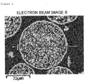
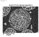
- the outer shell structure should be formed to be visually recognized in the cross-sectional SEM image of a ferrite particle if embedded in a resin and observed with an SEM. More specifically, the outer shell structure should have the outer periphery with a thickness in a certain range accounting for 80% or more of the circumferential length. More preferably, the proportion of the outer periphery in the circumferential length is 90% or more.
- the thickness of the outer shell structure is preferable to be 0.5 to 10 ⁇ m to achieve the intended object. If the thickness of the outer shell structure is less than 0.5 ⁇ m, mechanical strength of the ferrite particles is weak, and the various inherent powder properties may not be exhibited due to fracture. In particular, fractures generated in use as a carrier may cause scratches on a photo conductor drum. If the thickness of the outer shell structure exceeds 10 ⁇ m, no desired effect can be exhibited because the ferrite particles having the outer shell structure have no difference from conventional ferrite particles.
- the thickness of the outer shell structure is more preferable to be 0.5 to 8 ⁇ m, most preferable to be 0.5 to 6.5 ⁇ m.
- the thickness of the outer shell structure of particles is examined by the following procedures.
- a specimen for observing the cross section (for examining the thickness of the outer shell structure) is prepared by polishing the cross section of the molded ferrite particles embedded with a resin with a polishing machine and subjecting to gold vapor deposition.
- the SEM image of the specimen is photographed with JSM-6060A manufactured by JEOL Ltd., at an accelerating voltage of 5 kV, in a visual field at a 200-times of magnification.
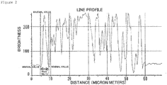
- the image data to be analyzed is introduced into an image analyzing software (Image-Pro PLUS) manufactured by Media Cybernetics Inc., through an interface. More specifically, after adjusting the contrast of the image obtained, the brightness of the image is extracted for each particle by the line profile function of the analyzing software.
- the procedure a straight line passing through the approximate center of a particle in the horizontal direction is drawn.
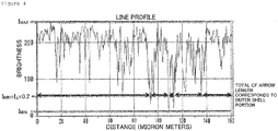
- the peak corresponding to the outer shell portion is put between two markers, and the width is assumed to be the thickness of the outer shell structure.
- the peak is defined as the two minimum values putting the maximum value between in the line profile.
- the contrast is preferable to be adjusted to make a brightness of the embedding resin portion (corresponding to background) 50% or less against to the maximum brightness.
- the same procedures are carried out for 30 particles in the same manner, and the average is assumed to be the thickness of the outer shell structure.
- the proportion of the outer shell structure in the circumferential length of the outer periphery can be determined by observing the cross-section of a ferrite particle embedded in a resin with an SEM as shown in Figures 1 and 3 , and image-processing the image obtained as described below in detail.
- the image is adjusted in the same manner as described above, and a line profile of circular or free-form curve (closed curve) is set for the outer shell structure of each particle.
- the maximum brightness of the profile is represented by I max
- the minimum brightness is represented by I min
- the difference between the maximum brightness and the minimum brightness is represented by I ⁇
- the range from I min or more and less than I min +I ⁇ ⁇ 0.2 is determined as a portion having no outer shell structure
- the range from I min +I ⁇ ⁇ 0.2 or more to I max or less is determined as the portion with an outer shell structure.
- the proportion of the outer periphery having a thickness in a certain range can be obtained by integrating the line profile lengths having a brightness of I min +I ⁇ ⁇ 0.2 or more to I max or less and divided by the line profile length (circumferential length) among the brightness data of the line profile length (circumferential length) obtained by the line profile function.
- the image is adjusted in the same manner as described above, and a straight line profile is set to pass through the approximate center of each particle.
- the maximum brightness of the profile is represented by I max
- the minimum brightness is represented by I min
- the difference between the maximum brightness and the minimum brightness is represented by I ⁇
- the range from I min or more to less than I min +I ⁇ ⁇ 0.2 is determined as a portion without ferrite
- the range from I min +I ⁇ ⁇ 0.2 or more to I max or less is determined as the ferrite portion.
- the proportion of the ferrite portion in the internal part of the ferrite particle can be obtained by the integrating the line profile lengths having a brightness of I min +I ⁇ ⁇ 0.2 or more to I max or less and divided by the line profile length (straight line) among the brightness data of the line profile length (straight line) obtained by the ling profile function.
- the same procedures are carried out for 30 particles, and the average is assumed to be the density of the internal part of the particle.
- the density of the ferrite particles between the portion having an outer shell structure (outer shell portion) and the internal part of the ferrite particle having a porous structure are different even the appearance of the ferrite particles according to the present invention is similar to that of conventional granular particles.
- Specific characteristics of the ferrite particles are, a large pore volume due to the low density of the internal part of the particle and a large pore diameter due to the high density of the outer shell portion.
- apparent density of the ferrite particle is lower than that of a conventional porous core due to an outer shell structure.
- the internal part of the ferrite particle can be impregnated with a suspension including dispersed resin or functional nanoparticles, with the surface of ferrite particle being exposed even though having a low apparent density.
- properties the conventional ferrite particles never achieved can be achieved because the outer shell portion and the internal porous portion can have individual functions.
- the ferrite particles according to the present invention contain 0.5 to 4 wt% of Mg and 3 to 20 wt% of Mn.
- the ferrite particles according to the present invention contain 47 to 70 wt% of Fe.
- the ferrite particles according to the present invention contain 0.5 to 4.5 wt% of Ti.
- Containing of Mg in the ferrite particles according to the present invention makes controlling of the magnetization easy. If Mg content is less than 0.5 wt%, the effect of addition is weak, and the magnetization cannot be sufficiently controlled. If Mg content exceeds 4 wt%, the magnetization decreases, and applications based on magnetic properties is made difficult.
- Containing of Mn in the ferrite particles according to the present invention makes control of the magnetization and the resistivity easy. If Mn content is less than 3 wt%, the effect of addition is weak, and the magnetization cannot be sufficiently controlled. If Mn content exceeds 20 wt%, content of Mn may approach to the stoichiometry of Mn ferrite, and the effect of containing decreases, i.e. containing of Mn may be meaningless. If Mn is contained, the magnetization may be controlled by firing temperature under a specific oxygen concentration.
- Containing of both elements Mn and Mg is preferable from the viewpoint of precise control of firing temperature.
- the magnetization of the ferrite particles is roughly controlled by the content of Mg, and the relation between firing temperature and magnetization is further controlled in more detail by the content of Mn.
- a developer composed of a ferrite carrier used the ferrite particles and full-color toners with good charging start can be obtained if the ferrite particles contain Mg.
- the resistivity can be increased. If Mg content is less than 0.5 wt%, sufficient effect of the containing of Mg is not achieved and the resistivity decreases, and the image quality is made poor with generation of fogging, poor tone reproduction.
- the strings of a magnetic brush is hardened to cause the generation of image defects such as brush streak marks due to excessively high magnetization.
- Mg content exceeds 4 wt%, not only the ferrite carrier scattering occurs due to lowered magnetization, but also the amount of moisture adsorbed increases due to the effect of hydroxyl group originating from Mg if the firing temperature is low, and make the environmental dependency of electrical properties such as the charge amount and the resistivity poor.
- Fe content in the ferrite particles according to the present invention is less than 47 wt%, no outer shell structure is formed. If Fe content exceeds 70 wt%, no effect of containing Mg is achieved, i.e. the ferrite particles might be the magnetite.
- the ferrite particles according to the present invention is preferable to contain 0.5 to 4.5 wt% of Ti.
- Ti has an effect to make the firing temperature low, and achieves not only reduced aggregated particles, but also uniform and wrinkled surface properties. If Ti content in the ferrite particles is less than 0.5 wt%, no effect of containing Ti is achieved, and no particle having an outer shell structure is manufactured. If Ti content exceeds 4.5 wt%, it is not preferable because using in applications based on magnetic properties of the ferrite particles is made difficult even the ferrite particles have outer shell structure are manufactured.
- the difference between Ti content in the ferrite particles according to the present invention and the Ti content in the ferrite particles without outer shell structure, i.e., the difference in Ti content between the vicinity of the surface of particle and the internal part of particle, is preferable to be 0.5 to 4.5 wt%.
- difference in Ti content is less than 0.5 wt%, no outer shell structure is formed due to the small coating amount of composite oxide particles. If difference is more than 4.5 wt%, it is not preferable because the magnetization tends to decrease, and using in applications based on magnetic properties is made difficult.
- the Ti oxides contained in an outer shell structure can be confirmed by EDX elemental mapping analysis on the cross-sectional sample for SEM.
- the Ti oxides include not only TiO 2 but also solid-dissolved compounds of one or more elements constituting the matrix of ferrite particle such as Fe-Ti oxides, Mg-Ti oxides, Sr-Ti oxides, Mn-Ti oxides, Mg-Fe-Ti oxides, Mg-Mn-Ti oxides, Sr-Fe-Ti oxides, Sr-Mn-Ti oxides, Sr-Mg-Ti oxides, Fe-Mn-Ti oxides, Fe-Mn-Mg-Ti oxides, Sr-Mn-Mg-Ti oxides, Sr-Fe-Mg-Ti oxides, and Sr-Fe-Mn-Ti oxides.
- the ferrite particles according to the present invention contain 0 to 1.5 wt% of Sr. Containing of Sr not only contributes to adjusting the resistivity and the surface properties, with an effect of maintaining high magnetization, but also influences on enhancing the charging ability of the ferrite particles. The effect is particularly large in the presence of Ti. If Sr content is more than 1.5 wt%, the residual magnetization and the coercive force increase, and using in applications based on soft magnetic properties of the ferrite particles is made difficult.
- Fe, Mg, Ti and Sr are determined as follows.
- Ferrite particles (ferrite carrier core material) in an amount of 0.2 g are weighed and completely dissolved in 60 ml of pure water with addition of 20 ml of 1 N hydrochloric acid and 20 ml of 1 N nitric acid with heating.
- the content of Fe, Mg, Ti and Sr in the aqueous solution thus prepared are determined by using an ICP analyzer (ICPS-1000IV manufactured by Shimadzu Corporation).
- the ferrite particle according to the present invention is preferable to have a magnetization of 55 to 85 Am 2 /kg in an applied magnetic field of 5K ⁇ 1000/4 ⁇ A/m, in the VSM examination. If the magnetization of the ferrite particles is less than 55 Am 2 /kg at 5K ⁇ 1000/4 ⁇ A/m, using in applications based on the magnetic properties of the ferrite particles cannot achieve its performance. The magnetization of the ferrite particles exceeding 85 Am 2 /kg at 5K ⁇ 1000/4 ⁇ A/m is not the composition according to the present invention.
- the magnetic properties are determined with a vibrating sample magnetometer (model: VSM-C7-10A (manufactured by Toei Industry Co., Ltd.)).
- a cell with an inner diameter of 5 mm and a height of 2 mm is filled with the sample particles (the ferrite particles) to be examined and set in the apparatus.
- sweeping is carried out under applied magnetic field up to 5K ⁇ 1000/4 ⁇ A/m.
- the applied magnetic field is reduced to draw the hysteresis curve on a recording paper.
- the magnetization under applied magnetic field up to 5K ⁇ 1000/4 ⁇ A/m is determined.
- the residual magnetization and the coercive force are determined in the same manner.
- the volume average particle diameter of the ferrite particles according to the present invention examined with a laser diffraction particle size distribution examiner is preferable to be 10 to 100 ⁇ m, more preferable to be 15 to 50 ⁇ m, most preferable to be 20 to 50 ⁇ m. If the volume average particle diameter of the ferrite particles is less than 10 ⁇ m, the portion with a low density in the internal part of a ferrite particle decreases relatively, and particles having a sufficiently low apparent density may not be manufactured.
- the diameter is preferable to be 100 ⁇ m or less from the viewpoint of reducing voids in densely filling a specified volume with the ferrite particles even the ferrite particles having an outer shell structure can be formed in the ferrite particles with a volume average particle diameter of more than 100 ⁇ m.
- the volume average particle diameter is examined by the laser diffraction/scattering method.
- a micro track particle size analyzer (Model 9320-X100) manufactured by Nikkiso Co., Ltd is used as the apparatus.
- the refractive index is assumed to be 2.42, and the examination is carried out under the environment temperature of 25 ⁇ 5°C and relative humidity of 55 ⁇ 15%.
- the volume average particle diameter (median diameter) in this specification refers to the cumulative 50% particle diameter below the sieve in the volume distribution mode. Water is used as a dispersion medium.
- BET specific surface area of the ferrite particles according to the present invention is preferable to be 0.2 to 1 m 2 /g, more preferable to be 0.2 to 0.85 m 2 /g.
- BET specific surface area is less than the range, it is not preferable because particles having the densely filled internal part are formed without sufficient formation of an outer shell structure. If BET specific surface area exceeds the range, the porous ferrite particles without formation of the outer shell structure is manufactured. Note that in examining of the BET specific surface area, the examination results may be influenced by the moisture on the surface of the sample ferrite particles. So, pre-treatment for removing the moisture put on the surface of the sample particles as much as possible is preferable.
- the BET specific surface area is examined with BET specific surface area analyzer (Macsorb HM model 1208 (manufactured by Mountech Co.)). Sample particles in an amount of about 5 to 7 g is placed in the standard sample cell for the exclusive use in the specific surface area analyzer to be accurately weighed with an analytical balance, and the sample particles (the ferrite particles) are set in an examination port for initiation of the examination. The examination carried out by the one-point method automatically calculate the BET specific surface area by inputting the weight of the sample particles. Note that the sample particles in an amount of about 20 g are separately taken onto a medicine wrapping paper and degassed to -0.1 MPa with a vacuum dryer as a pre-treatment before examination. After reaching the degree of vacuum to -0.1 MPa or less, the sample particles are heated at 200°C for 2 hours.
- BET specific surface area analyzer Macsorb HM model 1208 (manufactured by Mountech Co.)
- the ferrite particles according to the present invention is preferable to have the electric resistivity of 5 ⁇ 10 7 to 1 ⁇ 10 11 ⁇ at an applied voltage of 50 V for a 6.5-mm gap.
- the ferrite composition is close to magnetite or that the outer shell structure is insufficiently formed due to an insufficient Ti content. If the electric resistivity of the ferrite particles exceeds 1 ⁇ 10 11 ⁇ , excessive Ti content on the surface of a ferrite particle may decrease the magnetization.
- the electric resistivity is determined as follows.
- Non-magnetic plate electrodes (10 mm by 40 mm) are arranged in parallel with a gap of 6.5 mm, and the gap is filled with 200 mg of sample particles (the ferrite particles) weighed.
- a magnet surface magnetic flux density of 1500 Gauss and magnet area in contact with electrode of 10 mm by 30 mm is attached to the plate electrodes to hold the sample particles between the electrodes.
- Voltages of 50 V, 100 V, 250 V, 500 V and 1000 V are applied to examine the resistivity at each of the applied voltages with an insulation resistivity meter (SM-8210 manufactured by DKK-TOA Corporation).
- the ferrite particles are preferable to have the pore volume of 0.06 to 0.2 ml/g (60 to 200 ⁇ l/g) and the peak pore diameter of 0.7 to 2 ⁇ m.
- the ferrite particles with the pore volume of of less than 0.06 ml/g (60 ⁇ l/g) is not low in the apparent density because the internal part of the particles have the small pores. If the pore volume of the ferrite particles exceeds 0.2 ml/g (200 ⁇ l/g), the apparent density is excessively low, and problems may arise in applications based on magnetic properties of the ferrite particles due to the reduction in magnetic force of a particle as the magnetic particles.
- the ferrite particles having the peak pore diameter of more than 2 ⁇ m is the particle low in apparent density, and sufficient properties cannot be achieved in applications utilizing the portion having a low density in the internal part of the ferrite particles. If the peak pore diameter of the ferrite particles is less than 0.7 ⁇ m, the ferrite particles are most likely in a porous state without outer shell structure, and using in applications based on separate functions between the internal and external parts of a ferrite particle may be made difficult.
- pore volume and a peak pore diameter are in the ranges, moderately lightweight ferrite particles without the problems described above can be manufactured.
- the pore diameter and the pore volume of the ferrite particles are determined as follows.
- Mercury porosimeters Pascal 140 and Pascal 240 (manufactured by Thermo Fisher Scientific Inc.) are used in the determination.
- CD3P for powder use
- the first run includes the degassing with Pascal 140, followed by filling with mercury, to carry out the examination at a low-pressure region (0 to 400 kPa).
- the second run repeats degassing to carry out the examination at the low-pressure region (0 to 400 kPa).
- the total weight of the dilatometer, mercury, the capsule and the sample is examined. Then, the examination in a high-pressure region (0.1 MPa to 200 MPa) is carried out with Pascal 240. Based on the amount of mercury impregnated in the examination at the high-pressure region, the pore volume, the pore diameter distribution, and the peak pore diameter of the ferrite particles are determined. Note that, the surface tension of mercury was assumed to be 480 dyn/cm and the contact angle was assumed to be 141.3° in the calculation for determination of the pore diameter.
- the method for manufacturing the ferrite particles according to the present invention is carried out as follows, for example.
- the compounds of Fe, Mn and Mg, and the compounds of Sr, Ti according to needs are pulverized, mixed, calcined, and then pulverized with a rod mill, to prepare calcined ferrite particles.
- a preferred composition of the calcined ferrite particles contains 45 to 68 wt% of Fe, 0.5 to 4 wt% of Mg, 3 to 22 wt% of Mn, 0.25 to 6 wt% of Ti, and 0 to 2 wt% of Sr, for example.
- the calcined ferrite powder described above is added water, and a dispersant and a binder according to needs to finish a slurry. After viscosity adjustment of the slurry, granulation is carried out using a spray dryer. The particles are subjected to de-binder to prepare uncoated ferrite particles. The de-binder is carried out at 600 to 1000°C.
- the particle diameter D 50 of the slurry is preferable to be 0.5 to 4.5 ⁇ m. If the slurry particle diameter is in the range, the ferrite particles having a desired BET specific surface area can be manufactured. If the particle diameter D 50 of the slurry is less than 0.5 ⁇ m, the specific surface area of the calcined ferrite powder after pulverization is too big, and the ferrite particles having a desired BET specific surface area cannot be manufactured because the firing for coating the ferrite particles with TiO 2 particles proceeds excessively. If the slurry particle diameter D 30 exceeds 4.5 ⁇ m, desired ferrite particles may not be manufactured due to insufficient formation of the outer shell structure even the ferrite particles coated with TiO 2 particles are fired.
- the slurry particle diameter in the range described above may be achieved by controlling the pulverization time in preparation of the slurry for the granulation, selecting the pulverization medium to prepare the intended slurry particle diameter and particle size distribution, or classifying the raw material particles in the slurry by using a wet cyclone. If the wet cyclone is used, the solid content in the slurry is different after classification, and the adjustment of the solid content is required. However, as the intended slurry diameter can be achieved in a short time, the wet cyclone may be used in combination with the controlled pulverization time.
- the volume average particle diameter of TiO 2 particles for coating is preferable to be 0.05 to 3 ⁇ m. If the diameter is less than 0.05 ⁇ m, the ferrite particles including the part without outer shell structure may be manufactured because the TiO 2 particles for coating tend to aggregate when the fine particles are adhered on the surface of the uncoated ferrite particles, and the coating layer tends to be irregular even if the surface of the uncoated ferrite particles is coated with the desired amount of the TiO 2 particles. If the diameter exceeds 3 ⁇ m, the ferrite particles may include a part without outer shell structure because uniform adhesion on the uncoated ferrite particles is hardly achieved.
- the content of the TiO 2 particles for coating is preferable to be 0.8 to 7 wt% against to the uncoated ferrite particles although it depends on the volume average particle diameter. If the content is less than 0.8 wt%, a sufficient resistivity cannot be achieved after final firing. If the content exceeds 7 wt%, the content may cause problems in applications based on magnetic properties of the ferrite particles because TiO 2 particles for coating of ferrite particles adhered on the uncoated ferrite particles may aggregate each other to make the ferrite particles low in magnetization.
- TiO 2 particles for coating are added to the uncoated ferrite particles prepared, and mixed with a mixing mill to prepare raw material for the ferrite particles.
- the raw materials for the ferrite particles are subjected to final firing at 850 to 1230°C under an inert atmosphere or a weak oxidizing atmosphere such as nitrogen atmosphere or a mixed gas atmosphere of nitrogen and oxygen with the oxygen concentration of 3 vol% or less.
- the fired product is pulverized and classified to finish the ferrite particles.
- the conventional classification method such as wind classification, mesh filtration and sedimentation are used, and the particle size is adjusted to the desired particle diameter. If the dry collection is applied, the collection can be carried out by using a cyclone.
- the ferrite particles according to the present invention having each of the properties are thus manufactured.
- a surface treatment for electrification may be carried out.
- the surface treatment for electrification reduces the aggregation of TiO 2 particles for coating, and adhesion of TiO 2 particles for coating tends to be achieved before final firing. If the surface treatment agent having a reverse polarity to the charging polarity of the uncoated ferrite particles, effect of preventing the detachment of TiO 2 particles for coating adhered on the uncoated ferrite particles before final firing can be achieved.
- the method of adhering the TiO 2 particles for coating on the surface of the uncoated ferrite particles before final firing to be subjected to final firing is proposed as described above. If the TiO 2 particles for coating without subjecting to the pre-treatment for electrification in the dry method should be adhered to the surface of an uncoated ferrite particle before final firing, the properties of the ferrite particles obtained after final firing may be poor because the TiO 2 particles for coating to be adhered may severely aggregate to make the adhesion to the uncoated ferrite particles difficult or the composition may have large deviation due to the adhesion of large aggregates.
- the wet method of coating the surface of the uncoated ferrite particles with the TiO 2 particles for coating before final firing requires removal of the solvent for each of the raw materials of the surface-coated ferrite particles, the large-scale process is expensive.
- the dry method of coating the uncoated ferrite particles with the TiO 2 particles for coating just requires the surface treatment of the TiO 2 particles for coating, the processing is easy and cost increase is small.
- the resin molded product according to the present invention is manufactured by heat-curing a molded resin formed from a mixture of the ferrite particles and a resin.
- the molded resin product contains 50 to 99.5 wt% of the ferrite particles. If the content of the ferrite particles is less than 50 wt%, the properties of ferrite cannot be sufficiently exhibited even the ferrite particles are contained. If the content of the ferrite particles exceeds 99.5 wt%, molding may be impossible because a little resin is contained.
- the resin for use in the resin compound examples include an epoxy resin, a phenol resin, a melamine resin, a urea resin, and fluorine-contained resin, though not specifically limited.
- the resin compound contains a curing agent, a curing accelerator, and contains various additives such as silica particles according to needs.
- the calcined powder for the ferrite core material was pulverized for 1 hour with a wet bead mill. Then, PVA (10% aqueous solution) was added as a binder component in the amount of 1 wt% against to the slurry solid content, and the polycarboxylic acid-based dispersant was added to adjust the slurry viscosity 2 to 3 poise.
- the slurry particle diameter D 50 was 3.259 ⁇ m.
- the particles for the ferrite core material were prepared by pulverizing the slurry prepared and granulated and dried with a spray dryer, and subjected to a de-binder treatment at 850°C with a rotary kiln under a nitrogen atmosphere with the oxygen concentration of 0 vol%.
- the raw material for the ferrite particles prepared was maintained at 1010°C for 4 hours under the nitrogen atmosphere with the oxygen concentration of 0 vol% in an electric furnace for final firing. The fired material was then de-agglomerated and classified to finish the ferrite particles.
- the ferrite particles were prepared in the same manner as in Example 1, except that weighed ferrite raw material were 100 mol of Fe 2 O 3 , 5 mol of MgCO 3 , 26.6 mol of Mn 3 O 4 , and 0 mol of SrCO 3 .
- the ferrite particles were prepared in the same manner as in Example 1, except that weighed raw materials of the ferrite were 100 mol of Fe 2 O 3 , 20 mol of MgCO 3 , 6.65 mol of Mn 3 O 4 , and 0 mol of SrCO 3 .
- the ferrite particles were prepared in the same manner as in Example 1, except that weighed raw materials of the ferrite were 100 mol of Fe 2 O 3 , 5 mol of MgCO 3 , 5 mol of Mn 3 O 4 , and 0 mol of SrCO 3 .
- the ferrite particles were prepared in the same manner as in Example 1, except that weighed raw materials of the ferrite were n 100 mol of Fe 2 O 3 , 20 mol of MgCO 3 , 26.6 mol of Mn 3 O 4 , and 0 mol of SrCO 3 .
- the ferrite particles were prepared in the same manner as in Example 1, except that SrCO 3 was 0 mol and 2.5 wt% of TiO 2 particles for coating was added against to the particles for a ferrite core material.
- the ferrite particles were obtained in the same manner as in Example 1, except that SrCO 3 was 0 mol and 5 wt% of TiO 2 particles for coating was added against to the particles for a ferrite core material.
- the ferrite particles were prepared in the same manner as in Example 6, except that the final firing temperature was set at 950°C.
- the ferrite particles were prepared in the same manner as in Example 6, except that the final firing temperature was set at 1050°C.
- the ferrite particles were prepared in the same manner as in Example 1, except that the amount of SrCO 3 was 0 mol and the final firing temperature was set at 920°C.
- the ferrite particles were prepared in the same manner as in Example 1, except that the amount of SrCO 3 was 0 mol and no TiO 2 particle for coating was added to the particles for a ferrite core material.
- the ferrite particles were prepared in the same manner as in Example 1, except that the amount of SrCO 3 was 0 mol and the final firing temperature was set at 1165°C.
- Table 1 shows the blending ratio of the ferrite particles used (molar ratio of raw material charged), the amount of carbon black, the calcination conditions (calcination temperature and calcination atmosphere), the final granulation conditions (slurry particle diameter and amount of PVA added), the de-binder conditions (treatment temperature and treatment atmosphere), the mixing conditions of TiO 2 (amount added and mixing conditions) and the final firing conditions (final firing temperature and final firing atmosphere) in Examples 1 to 9 and Comparative Examples 1 to 3.
- Table 2 shows the composition, the magnetic properties (magnetization, residual magnetization and coercive force) and the shape (cross-sectional shape, proportion of the portion of outer shell structure in the circumferential length of the outer periphery, and the thickness of the outer shell structure) of the ferrite particles prepared.
- Table 3 shows the powder properties (BET specific surface area, average particle diameter, apparent density, true density, pore volume and peak pore diameter) and the bridge resistance of 6.5 mm-gap (50 V, 100 V, 250 V, 500 V and 1000 V) of the ferrite particles in Examples 1 to 9 and Comparative Examples 1 to 3. Examination methods are as described above.
- any of the ferrite particles prepared in Examples 1 to 9 has the outer shell structure.
- the ferrite particles in Comparative Example 1 have no outer shell structure even a porous structure was formed because low firing temperature was loaded on the ferrite particles.
- the ferrite particles in Comparative Example 2 have no outer shell structure because high firing temperature was loaded on the ferrite particles.
- the ferrite particles in Comparative Example 3 have no outer shell structure because no TiO 2 particle was added to the particles for a ferrite core material.
- the resin solution having the solid resin content of 6.5 wt% was prepared by diluting the polyamide-imide resin (HPC-1000 manufactured by Hitachi Chemical Co., Ltd.) with water against to 100 parts by weight of the ferrite particles prepared in Example 1.
- the resin solution and the ferrite particles were mixed by stirring with a versatile mixer to prepare a mixture.
- the mixture was baked for 2 hours with a hot air dryer at 180°C to finish impregnation of the resin into the ferrite particles.
- the aggregated ferrite particles were de-agglomerated to prepare the ferrite particles filled with a resin.
- the resin solution including 1 wt% of a polyamide-imide resin against to 100 wt% of the ferrite particles filled with resin was prepared.
- the resin solution, the ferrite particles were coated with the resin with a fluidized bed coating device, and the resulted mixture was baked for 2 hours with a hot air dryer set at 180°C, and the ferrite particles filled with a resin were coated with a resin.
- the aggregated ferrite particles were de-agglomerated to prepare the ferrite particles filled with a resin coated with a resin.
- the resin solution having a polyamide-imide resin content of 2 wt% against to 100 parts by weight of the ferrite particles prepared in Example 1 was prepared.
- the ferrite particles were coated with a resin with a fluidized bed coating device, and the resin coated mixture was baked for 2 hours with a hot air dryer at 180°C, and the ferrite particles filled with a resin were coated with a resin. Then, the aggregated ferrite particles were de-agglomerated to prepare the ferrite particles coated with a resin.
- Table 4 shows the ferrite particles used, the conditions for resin filling (resin for filling, amount of resin filled, device used in filling the resin), curing conditions (temperature and time), coating conditions (resin for coating, amount of resin coated, and device used in coating), and curing conditions in Examples 10 to 12.
- the ferrite particles in an amount of 90 parts by weight prepared in Example 1 and acrylic silicone resin powder in an amount of 10 parts by weight were mixed. Then, the mixture in an amount of 1.0 g was poured in a cylindrical pressing mold having a diameter of 13 mm to press mold at 15 MPa. The molded material prepared was heat treated at 200°C for 2 hours with a hot air dryer, and the resin was melted and solidified. The thickness of the molded product after the heat treatment was examined.
- the molded material was prepared in the same manner as in Example 13, except that the ferrite particles were replaced with the ferrite particles prepared in Example 8, and the thickness of the molded product was examined.
- the molded material was prepared in the same manner as in Example 13, except that the ferrite particles were replaced with the ferrite particles prepared in Example 9, and the thickness of the molded product was examined.
- the molded material was prepared in the same manner as in Example 13, except that a styrene-acrylic resin was used as a binder resin and the heat treatment temperature was changed to 220°C, and the thickness of the molded product was examined.
- the molded material was prepared in the same manner as in Example 13, except that a fluorine-contained resin was used as a binder resin and the heat treatment temperature was changed to 165°C, and the thickness of the molded product was examined.
- a molded material was prepared in the same manner as in Example 17, except that the ferrite particles were replaced with the ferrite particles filled with resin prepared in Example 10, and the thickness of the molded product was examined.
- a molded material was prepared in the same manner as in Example 17, except that the ferrite particles were replaced with the resin-coated ferrite particles filled with resin prepared in Example 11, and the thickness of the molded product was examined.
- a molded material was prepared in the same manner as in Example 17, except that the ferrite particles were replaced with the resin-coated ferrite particles prepared in Example 12, and the thickness of the molded product was examined.
- a molded material was prepared in the same manner as in Example 13, except that the ferrite particles were replaced with the ferrite particles prepared in Comparative Example 3, and the thickness of the molded product was examined.
- Table 5 shows the ferrite particles used (magnetic filler), the binder resin, the mixing weight ratio between magnetic filler and binder resin, the preparation of the test piece (charge weight of mixture and molding pressure), the heat treatment (heat treatment temperature and treatment time), the thickness of molded products and the density of molded product in Examples 13 to 20 and Comparative Example 4.
- Example 5 Magnetic filler Binder resin Mixing ratio between magnetic filler and binder resin Preparation of test piece Heat treatment Thickness of molded product Density of molded product Charge weight of mixture Molding pressure Temperature Time g Mpa °C hr Mm g/cm 3
- Example 13 Ferrite particle obtained in Example 1 A 90:10 1 15 200 2 2.65 2.84
- Example 14 Ferrite particle obtained in Example 8 90:10 1 15 200 2 2.80 2.69
- Example 15 Ferrite particle obtained in Example 9 90:10 1 15 200 2 2.60 2.9
- Example 16 Ferrite particle obtained in Example 1 B 90:10 1 1.5 220 2 2.65 2.84
- Example 17 Ferrite particle obtained in Example 1 C 90:10 1 15 165 2 2.55 2.96
- Example 18 Ferrite particle filled with resin obtained in Example 10 90:10 1 15 165 2 2.45 3.07
- Example 19 Resin-coated ferrite particle filled with resin obtained in Example 11 90:10 1 15 165 2 2.40 3.14
- Example 20 Resin-coated fer
- the ferrite particles according to the present invention is low in apparent density due to the outer shell structure. So, the ferrite particles fill the specified volume with a small weight while maintaining various properties in a controllable state. As a result, the resin molded product containing the ferrite particles as a magnetic filler is low in density, and is applicable in applications such as radio wave absorb.
Landscapes
- Chemical & Material Sciences (AREA)
- Organic Chemistry (AREA)
- Engineering & Computer Science (AREA)
- Power Engineering (AREA)
- Health & Medical Sciences (AREA)
- Dispersion Chemistry (AREA)
- Polymers & Plastics (AREA)
- Medicinal Chemistry (AREA)
- Chemical Kinetics & Catalysis (AREA)
- Inorganic Chemistry (AREA)
- General Health & Medical Sciences (AREA)
- Dermatology (AREA)
- Compounds Of Iron (AREA)
- Soft Magnetic Materials (AREA)
- Compositions Of Macromolecular Compounds (AREA)
- Hard Magnetic Materials (AREA)
- Developing Agents For Electrophotography (AREA)
Claims (8)
- Ein magnetischer Füllstoff, der aus Ferritteilchen mit einer Außenhüllenstruktur, die ein Ti-Oxid enthält, zusammengesetzt ist, dadurch gekennzeichnet, dass die Ferritteilchen 47 bis 70 Gew.-% Fe, 0,5 bis 4 Gew.-% Mg, 3 bis 20 Gew.-% Mn, 0,5 bis 4,5 Gew.-% Ti und 0 bis 1,5 Gew.-% Sr enthalten.
- Der magnetische Füllstoff gemäß Anspruch 1, wobei die Dicke der Außenhüllenstruktur der Ferritteilchen 0,5 bis 10 µm beträgt.
- Der magnetische Füllstoff gemäß Anspruch 1 oder 2, wobei die Dichte des inneren Teils des Ferritteilchens geringer ist als die Dichte der Außenhüllenstruktur.
- Der magnetische Füllstoff gemäß einem der Ansprüche 1 bis 3, wobei der volumengemittelte Teilchendurchmesser der Ferritteilchen 10 bis 100 µm beträgt.
- Der magnetische Füllstoff gemäß einem der Ansprüche 1 bis 4, wobei die Ferritteilchen mit einem Harz beschichtet sind.
- Der magnetische Füllstoff gemäß einem der Ansprüche 1 bis 4, wobei die Ferritteilchen mit einem Harz imprägniert sind.
- Der magnetische Füllstoff gemäß Anspruch 6, wobei die Ferritteilchen mit einem Harz beschichtet sind.
- Ein Harzformgegenstand, der aus dem magnetischen Füllstoff gemäß einem der Ansprüche 1 bis 7 gebildet ist.
Applications Claiming Priority (2)
| Application Number | Priority Date | Filing Date | Title |
|---|---|---|---|
| JP2015013795A JP6127324B2 (ja) | 2015-01-28 | 2015-01-28 | 磁性フィラー |
| PCT/JP2016/052152 WO2016121744A1 (ja) | 2015-01-28 | 2016-01-26 | 磁性フィラー |
Publications (3)
| Publication Number | Publication Date |
|---|---|
| EP3252017A1 EP3252017A1 (de) | 2017-12-06 |
| EP3252017A4 EP3252017A4 (de) | 2018-09-05 |
| EP3252017B1 true EP3252017B1 (de) | 2020-03-04 |
Family
ID=56543355
Family Applications (1)
| Application Number | Title | Priority Date | Filing Date |
|---|---|---|---|
| EP16743347.3A Active EP3252017B1 (de) | 2015-01-28 | 2016-01-26 | Magnetischer füllstoff |
Country Status (7)
| Country | Link |
|---|---|
| US (1) | US20170369672A1 (de) |
| EP (1) | EP3252017B1 (de) |
| JP (1) | JP6127324B2 (de) |
| KR (1) | KR102387842B1 (de) |
| CN (1) | CN107207278B (de) |
| TW (1) | TWI671263B (de) |
| WO (1) | WO2016121744A1 (de) |
Families Citing this family (2)
| Publication number | Priority date | Publication date | Assignee | Title |
|---|---|---|---|---|
| WO2019159799A1 (ja) * | 2018-02-13 | 2019-08-22 | パウダーテック株式会社 | 複合粒子、粉末、樹脂組成物および成形体 |
| TWI850353B (zh) * | 2019-03-20 | 2024-08-01 | 日商味之素股份有限公司 | 樹脂組成物 |
Family Cites Families (8)
| Publication number | Priority date | Publication date | Assignee | Title |
|---|---|---|---|---|
| JPH05299870A (ja) | 1992-04-20 | 1993-11-12 | Nec Corp | 電波吸収材料 |
| JP3565421B2 (ja) * | 1999-04-13 | 2004-09-15 | 日鉄鉱業株式会社 | 白色粉体およびその製造方法 |
| JP2006173266A (ja) * | 2004-12-14 | 2006-06-29 | Jsr Corp | クリーニングシートおよびその製造方法 |
| US7670679B2 (en) * | 2006-05-30 | 2010-03-02 | General Electric Company | Core-shell ceramic particulate and method of making |
| JP5488890B2 (ja) * | 2009-11-27 | 2014-05-14 | パウダーテック株式会社 | 電子写真現像剤用多孔質フェライト芯材、樹脂充填型フェライトキャリア及び該フェライトキャリアを用いた電子写真現像剤 |
| CN103046138A (zh) * | 2011-10-12 | 2013-04-17 | 中国科学院福建物质结构研究所 | 一种铁电单晶铌铁酸铅-铌镱酸铅-钛酸铅及其制备方法 |
| JP6163652B2 (ja) * | 2012-01-13 | 2017-07-19 | パウダーテック株式会社 | 電子写真現像剤用多孔質フェライト芯材、樹脂被覆フェライトキャリア及び該フェライトキャリアを用いた電子写真現像剤 |
| JP6156626B2 (ja) * | 2013-03-19 | 2017-07-05 | パウダーテック株式会社 | 電子写真現像剤用フェライトキャリア芯材及びフェライトキャリア、並びに該フェライトキャリアを用いた電子写真現像剤 |
-
2015
- 2015-01-28 JP JP2015013795A patent/JP6127324B2/ja active Active
-
2016
- 2016-01-26 TW TW105102305A patent/TWI671263B/zh active
- 2016-01-26 WO PCT/JP2016/052152 patent/WO2016121744A1/ja not_active Ceased
- 2016-01-26 KR KR1020177019677A patent/KR102387842B1/ko active Active
- 2016-01-26 CN CN201680005397.0A patent/CN107207278B/zh active Active
- 2016-01-26 US US15/544,358 patent/US20170369672A1/en not_active Abandoned
- 2016-01-26 EP EP16743347.3A patent/EP3252017B1/de active Active
Non-Patent Citations (1)
| Title |
|---|
| None * |
Also Published As
| Publication number | Publication date |
|---|---|
| EP3252017A1 (de) | 2017-12-06 |
| US20170369672A1 (en) | 2017-12-28 |
| TWI671263B (zh) | 2019-09-11 |
| EP3252017A4 (de) | 2018-09-05 |
| TW201630817A (zh) | 2016-09-01 |
| CN107207278A (zh) | 2017-09-26 |
| CN107207278B (zh) | 2020-02-18 |
| KR20170108950A (ko) | 2017-09-27 |
| KR102387842B1 (ko) | 2022-04-15 |
| JP6127324B2 (ja) | 2017-05-17 |
| WO2016121744A1 (ja) | 2016-08-04 |
| JP2016138189A (ja) | 2016-08-04 |
Similar Documents
| Publication | Publication Date | Title |
|---|---|---|
| EP3196168B1 (de) | Kugelförmige ferritpartikel in nanogrösse und verfahren zur herstellung davon | |
| EP3248942B1 (de) | Harzzusammensetzung enthaltend ein ferritpulver in form hexagonaler plättchen, verfahren zu deren herstellung und formgegenstand geformt aus der harzzusammensetzung | |
| EP2131248B1 (de) | Trägerkernmaterial für einen elektrofotografischen entwickler und verfahren zu seiner herstellung, träger für einen elektrofotografischen entwickler und elektrofotografischer entwickler | |
| EP3252536A1 (de) | Ferritteilchen mit aussenhüllenstruktur | |
| EP3251735B1 (de) | Ferritteilchen für filtermaterial mit aussenschalenstruktur | |
| EP3252017B1 (de) | Magnetischer füllstoff | |
| EP3252016B1 (de) | Ferritteilchen für katalysatorträger mit aussenschalenstruktur | |
| EP3252015B1 (de) | Plattenförmige ferritteilchen für pigment mit metallischem glanz | |
| JP2016138015A5 (de) | ||
| JP2016138189A5 (de) | ||
| JP5943465B2 (ja) | フェライト粒子並びにそれを用いた電子写真現像用キャリア及び電子写真用現像剤 |
Legal Events
| Date | Code | Title | Description |
|---|---|---|---|
| STAA | Information on the status of an ep patent application or granted ep patent |
Free format text: STATUS: THE INTERNATIONAL PUBLICATION HAS BEEN MADE |
|
| PUAI | Public reference made under article 153(3) epc to a published international application that has entered the european phase |
Free format text: ORIGINAL CODE: 0009012 |
|
| STAA | Information on the status of an ep patent application or granted ep patent |
Free format text: STATUS: REQUEST FOR EXAMINATION WAS MADE |
|
| 17P | Request for examination filed |
Effective date: 20170826 |
|
| AK | Designated contracting states |
Kind code of ref document: A1 Designated state(s): AL AT BE BG CH CY CZ DE DK EE ES FI FR GB GR HR HU IE IS IT LI LT LU LV MC MK MT NL NO PL PT RO RS SE SI SK SM TR |
|
| AX | Request for extension of the european patent |
Extension state: BA ME |
|
| DAV | Request for validation of the european patent (deleted) | ||
| DAX | Request for extension of the european patent (deleted) | ||
| A4 | Supplementary search report drawn up and despatched |
Effective date: 20180808 |
|
| RIC1 | Information provided on ipc code assigned before grant |
Ipc: C01G 49/00 20060101AFI20180802BHEP Ipc: C08K 3/22 20060101ALI20180802BHEP Ipc: C08K 9/04 20060101ALI20180802BHEP Ipc: C08L 101/00 20060101ALI20180802BHEP Ipc: H01F 1/37 20060101ALI20180802BHEP Ipc: H01F 1/36 20060101ALI20180802BHEP |
|
| GRAP | Despatch of communication of intention to grant a patent |
Free format text: ORIGINAL CODE: EPIDOSNIGR1 |
|
| STAA | Information on the status of an ep patent application or granted ep patent |
Free format text: STATUS: GRANT OF PATENT IS INTENDED |
|
| INTG | Intention to grant announced |
Effective date: 20190917 |
|
| GRAS | Grant fee paid |
Free format text: ORIGINAL CODE: EPIDOSNIGR3 |
|
| GRAA | (expected) grant |
Free format text: ORIGINAL CODE: 0009210 |
|
| STAA | Information on the status of an ep patent application or granted ep patent |
Free format text: STATUS: THE PATENT HAS BEEN GRANTED |
|
| AK | Designated contracting states |
Kind code of ref document: B1 Designated state(s): AL AT BE BG CH CY CZ DE DK EE ES FI FR GB GR HR HU IE IS IT LI LT LU LV MC MK MT NL NO PL PT RO RS SE SI SK SM TR |
|
| REG | Reference to a national code |
Ref country code: GB Ref legal event code: FG4D |
|
| REG | Reference to a national code |
Ref country code: CH Ref legal event code: EP |
|
| REG | Reference to a national code |
Ref country code: AT Ref legal event code: REF Ref document number: 1240178 Country of ref document: AT Kind code of ref document: T Effective date: 20200315 |
|
| REG | Reference to a national code |
Ref country code: DE Ref legal event code: R096 Ref document number: 602016031080 Country of ref document: DE |
|
| REG | Reference to a national code |
Ref country code: IE Ref legal event code: FG4D |
|
| PG25 | Lapsed in a contracting state [announced via postgrant information from national office to epo] |
Ref country code: RS Free format text: LAPSE BECAUSE OF FAILURE TO SUBMIT A TRANSLATION OF THE DESCRIPTION OR TO PAY THE FEE WITHIN THE PRESCRIBED TIME-LIMIT Effective date: 20200304 Ref country code: FI Free format text: LAPSE BECAUSE OF FAILURE TO SUBMIT A TRANSLATION OF THE DESCRIPTION OR TO PAY THE FEE WITHIN THE PRESCRIBED TIME-LIMIT Effective date: 20200304 Ref country code: NO Free format text: LAPSE BECAUSE OF FAILURE TO SUBMIT A TRANSLATION OF THE DESCRIPTION OR TO PAY THE FEE WITHIN THE PRESCRIBED TIME-LIMIT Effective date: 20200604 |
|
| REG | Reference to a national code |
Ref country code: NL Ref legal event code: MP Effective date: 20200304 |
|
| PG25 | Lapsed in a contracting state [announced via postgrant information from national office to epo] |
Ref country code: BG Free format text: LAPSE BECAUSE OF FAILURE TO SUBMIT A TRANSLATION OF THE DESCRIPTION OR TO PAY THE FEE WITHIN THE PRESCRIBED TIME-LIMIT Effective date: 20200604 Ref country code: GR Free format text: LAPSE BECAUSE OF FAILURE TO SUBMIT A TRANSLATION OF THE DESCRIPTION OR TO PAY THE FEE WITHIN THE PRESCRIBED TIME-LIMIT Effective date: 20200605 Ref country code: LV Free format text: LAPSE BECAUSE OF FAILURE TO SUBMIT A TRANSLATION OF THE DESCRIPTION OR TO PAY THE FEE WITHIN THE PRESCRIBED TIME-LIMIT Effective date: 20200304 Ref country code: SE Free format text: LAPSE BECAUSE OF FAILURE TO SUBMIT A TRANSLATION OF THE DESCRIPTION OR TO PAY THE FEE WITHIN THE PRESCRIBED TIME-LIMIT Effective date: 20200304 Ref country code: HR Free format text: LAPSE BECAUSE OF FAILURE TO SUBMIT A TRANSLATION OF THE DESCRIPTION OR TO PAY THE FEE WITHIN THE PRESCRIBED TIME-LIMIT Effective date: 20200304 |
|
| REG | Reference to a national code |
Ref country code: LT Ref legal event code: MG4D |
|
| PG25 | Lapsed in a contracting state [announced via postgrant information from national office to epo] |
Ref country code: NL Free format text: LAPSE BECAUSE OF FAILURE TO SUBMIT A TRANSLATION OF THE DESCRIPTION OR TO PAY THE FEE WITHIN THE PRESCRIBED TIME-LIMIT Effective date: 20200304 |
|
| PG25 | Lapsed in a contracting state [announced via postgrant information from national office to epo] |
Ref country code: RO Free format text: LAPSE BECAUSE OF FAILURE TO SUBMIT A TRANSLATION OF THE DESCRIPTION OR TO PAY THE FEE WITHIN THE PRESCRIBED TIME-LIMIT Effective date: 20200304 Ref country code: SM Free format text: LAPSE BECAUSE OF FAILURE TO SUBMIT A TRANSLATION OF THE DESCRIPTION OR TO PAY THE FEE WITHIN THE PRESCRIBED TIME-LIMIT Effective date: 20200304 Ref country code: PT Free format text: LAPSE BECAUSE OF FAILURE TO SUBMIT A TRANSLATION OF THE DESCRIPTION OR TO PAY THE FEE WITHIN THE PRESCRIBED TIME-LIMIT Effective date: 20200729 Ref country code: ES Free format text: LAPSE BECAUSE OF FAILURE TO SUBMIT A TRANSLATION OF THE DESCRIPTION OR TO PAY THE FEE WITHIN THE PRESCRIBED TIME-LIMIT Effective date: 20200304 Ref country code: LT Free format text: LAPSE BECAUSE OF FAILURE TO SUBMIT A TRANSLATION OF THE DESCRIPTION OR TO PAY THE FEE WITHIN THE PRESCRIBED TIME-LIMIT Effective date: 20200304 Ref country code: EE Free format text: LAPSE BECAUSE OF FAILURE TO SUBMIT A TRANSLATION OF THE DESCRIPTION OR TO PAY THE FEE WITHIN THE PRESCRIBED TIME-LIMIT Effective date: 20200304 Ref country code: IS Free format text: LAPSE BECAUSE OF FAILURE TO SUBMIT A TRANSLATION OF THE DESCRIPTION OR TO PAY THE FEE WITHIN THE PRESCRIBED TIME-LIMIT Effective date: 20200704 Ref country code: SK Free format text: LAPSE BECAUSE OF FAILURE TO SUBMIT A TRANSLATION OF THE DESCRIPTION OR TO PAY THE FEE WITHIN THE PRESCRIBED TIME-LIMIT Effective date: 20200304 Ref country code: CZ Free format text: LAPSE BECAUSE OF FAILURE TO SUBMIT A TRANSLATION OF THE DESCRIPTION OR TO PAY THE FEE WITHIN THE PRESCRIBED TIME-LIMIT Effective date: 20200304 |
|
| REG | Reference to a national code |
Ref country code: AT Ref legal event code: MK05 Ref document number: 1240178 Country of ref document: AT Kind code of ref document: T Effective date: 20200304 |
|
| REG | Reference to a national code |
Ref country code: DE Ref legal event code: R097 Ref document number: 602016031080 Country of ref document: DE |
|
| PLBE | No opposition filed within time limit |
Free format text: ORIGINAL CODE: 0009261 |
|
| STAA | Information on the status of an ep patent application or granted ep patent |
Free format text: STATUS: NO OPPOSITION FILED WITHIN TIME LIMIT |
|
| PG25 | Lapsed in a contracting state [announced via postgrant information from national office to epo] |
Ref country code: IT Free format text: LAPSE BECAUSE OF FAILURE TO SUBMIT A TRANSLATION OF THE DESCRIPTION OR TO PAY THE FEE WITHIN THE PRESCRIBED TIME-LIMIT Effective date: 20200304 Ref country code: AT Free format text: LAPSE BECAUSE OF FAILURE TO SUBMIT A TRANSLATION OF THE DESCRIPTION OR TO PAY THE FEE WITHIN THE PRESCRIBED TIME-LIMIT Effective date: 20200304 Ref country code: DK Free format text: LAPSE BECAUSE OF FAILURE TO SUBMIT A TRANSLATION OF THE DESCRIPTION OR TO PAY THE FEE WITHIN THE PRESCRIBED TIME-LIMIT Effective date: 20200304 |
|
| 26N | No opposition filed |
Effective date: 20201207 |
|
| PG25 | Lapsed in a contracting state [announced via postgrant information from national office to epo] |
Ref country code: SI Free format text: LAPSE BECAUSE OF FAILURE TO SUBMIT A TRANSLATION OF THE DESCRIPTION OR TO PAY THE FEE WITHIN THE PRESCRIBED TIME-LIMIT Effective date: 20200304 Ref country code: PL Free format text: LAPSE BECAUSE OF FAILURE TO SUBMIT A TRANSLATION OF THE DESCRIPTION OR TO PAY THE FEE WITHIN THE PRESCRIBED TIME-LIMIT Effective date: 20200304 |
|
| PG25 | Lapsed in a contracting state [announced via postgrant information from national office to epo] |
Ref country code: MC Free format text: LAPSE BECAUSE OF FAILURE TO SUBMIT A TRANSLATION OF THE DESCRIPTION OR TO PAY THE FEE WITHIN THE PRESCRIBED TIME-LIMIT Effective date: 20200304 |
|
| REG | Reference to a national code |
Ref country code: CH Ref legal event code: PL |
|
| GBPC | Gb: european patent ceased through non-payment of renewal fee |
Effective date: 20210126 |
|
| PG25 | Lapsed in a contracting state [announced via postgrant information from national office to epo] |
Ref country code: LU Free format text: LAPSE BECAUSE OF NON-PAYMENT OF DUE FEES Effective date: 20210126 |
|
| REG | Reference to a national code |
Ref country code: BE Ref legal event code: MM Effective date: 20210131 |
|
| PG25 | Lapsed in a contracting state [announced via postgrant information from national office to epo] |
Ref country code: FR Free format text: LAPSE BECAUSE OF NON-PAYMENT OF DUE FEES Effective date: 20210131 |
|
| PG25 | Lapsed in a contracting state [announced via postgrant information from national office to epo] |
Ref country code: GB Free format text: LAPSE BECAUSE OF NON-PAYMENT OF DUE FEES Effective date: 20210126 Ref country code: LI Free format text: LAPSE BECAUSE OF NON-PAYMENT OF DUE FEES Effective date: 20210131 Ref country code: CH Free format text: LAPSE BECAUSE OF NON-PAYMENT OF DUE FEES Effective date: 20210131 |
|
| PG25 | Lapsed in a contracting state [announced via postgrant information from national office to epo] |
Ref country code: IE Free format text: LAPSE BECAUSE OF NON-PAYMENT OF DUE FEES Effective date: 20210126 |
|
| PG25 | Lapsed in a contracting state [announced via postgrant information from national office to epo] |
Ref country code: BE Free format text: LAPSE BECAUSE OF NON-PAYMENT OF DUE FEES Effective date: 20210131 |
|
| P01 | Opt-out of the competence of the unified patent court (upc) registered |
Effective date: 20230428 |
|
| PG25 | Lapsed in a contracting state [announced via postgrant information from national office to epo] |
Ref country code: CY Free format text: LAPSE BECAUSE OF FAILURE TO SUBMIT A TRANSLATION OF THE DESCRIPTION OR TO PAY THE FEE WITHIN THE PRESCRIBED TIME-LIMIT Effective date: 20200304 |
|
| PG25 | Lapsed in a contracting state [announced via postgrant information from national office to epo] |
Ref country code: HU Free format text: LAPSE BECAUSE OF FAILURE TO SUBMIT A TRANSLATION OF THE DESCRIPTION OR TO PAY THE FEE WITHIN THE PRESCRIBED TIME-LIMIT; INVALID AB INITIO Effective date: 20160126 |
|
| PG25 | Lapsed in a contracting state [announced via postgrant information from national office to epo] |
Ref country code: MK Free format text: LAPSE BECAUSE OF FAILURE TO SUBMIT A TRANSLATION OF THE DESCRIPTION OR TO PAY THE FEE WITHIN THE PRESCRIBED TIME-LIMIT Effective date: 20200304 |
|
| PG25 | Lapsed in a contracting state [announced via postgrant information from national office to epo] |
Ref country code: TR Free format text: LAPSE BECAUSE OF FAILURE TO SUBMIT A TRANSLATION OF THE DESCRIPTION OR TO PAY THE FEE WITHIN THE PRESCRIBED TIME-LIMIT Effective date: 20200304 |
|
| PG25 | Lapsed in a contracting state [announced via postgrant information from national office to epo] |
Ref country code: MT Free format text: LAPSE BECAUSE OF FAILURE TO SUBMIT A TRANSLATION OF THE DESCRIPTION OR TO PAY THE FEE WITHIN THE PRESCRIBED TIME-LIMIT Effective date: 20200304 |
|
| PGFP | Annual fee paid to national office [announced via postgrant information from national office to epo] |
Ref country code: DE Payment date: 20241203 Year of fee payment: 10 |