EP3247595B1 - Dispositif de nettoyage d'une camera d'aide a la conduite d'un vehicule automobile - Google Patents
Dispositif de nettoyage d'une camera d'aide a la conduite d'un vehicule automobile Download PDFInfo
- Publication number
- EP3247595B1 EP3247595B1 EP15810740.9A EP15810740A EP3247595B1 EP 3247595 B1 EP3247595 B1 EP 3247595B1 EP 15810740 A EP15810740 A EP 15810740A EP 3247595 B1 EP3247595 B1 EP 3247595B1
- Authority
- EP
- European Patent Office
- Prior art keywords
- cleaning
- video camera
- camera
- vehicle
- face
- Prior art date
- Legal status (The legal status is an assumption and is not a legal conclusion. Google has not performed a legal analysis and makes no representation as to the accuracy of the status listed.)
- Active
Links
Images
Classifications
-
- B—PERFORMING OPERATIONS; TRANSPORTING
- B08—CLEANING
- B08B—CLEANING IN GENERAL; PREVENTION OF FOULING IN GENERAL
- B08B3/00—Cleaning by methods involving the use or presence of liquid or steam
- B08B3/02—Cleaning by the force of jets or sprays
-
- B—PERFORMING OPERATIONS; TRANSPORTING
- B60—VEHICLES IN GENERAL
- B60R—VEHICLES, VEHICLE FITTINGS, OR VEHICLE PARTS, NOT OTHERWISE PROVIDED FOR
- B60R11/00—Arrangements for holding or mounting articles, not otherwise provided for
- B60R11/04—Mounting of cameras operative during drive; Arrangement of controls thereof relative to the vehicle
-
- B—PERFORMING OPERATIONS; TRANSPORTING
- B60—VEHICLES IN GENERAL
- B60R—VEHICLES, VEHICLE FITTINGS, OR VEHICLE PARTS, NOT OTHERWISE PROVIDED FOR
- B60R19/00—Wheel guards; Radiator guards, e.g. grilles; Obstruction removers; Fittings damping bouncing force in collisions
- B60R19/02—Bumpers, i.e. impact receiving or absorbing members for protecting vehicles or fending off blows from other vehicles or objects
- B60R19/48—Bumpers, i.e. impact receiving or absorbing members for protecting vehicles or fending off blows from other vehicles or objects combined with, or convertible into, other devices or objects, e.g. bumpers combined with road brushes, bumpers convertible into beds
-
- B—PERFORMING OPERATIONS; TRANSPORTING
- B60—VEHICLES IN GENERAL
- B60S—SERVICING, CLEANING, REPAIRING, SUPPORTING, LIFTING, OR MANOEUVRING OF VEHICLES, NOT OTHERWISE PROVIDED FOR
- B60S1/00—Cleaning of vehicles
- B60S1/02—Cleaning windscreens, windows or optical devices
- B60S1/46—Cleaning windscreens, windows or optical devices using liquid; Windscreen washers
- B60S1/48—Liquid supply therefor
- B60S1/52—Arrangement of nozzles; Liquid spreading means
- B60S1/522—Arrangement of nozzles; Liquid spreading means moving liquid spreading means, e.g. arranged in wiper arms
- B60S1/528—Arrangement of nozzles; Liquid spreading means moving liquid spreading means, e.g. arranged in wiper arms the spreading means being moved between a rest position and a working position
-
- B—PERFORMING OPERATIONS; TRANSPORTING
- B60—VEHICLES IN GENERAL
- B60S—SERVICING, CLEANING, REPAIRING, SUPPORTING, LIFTING, OR MANOEUVRING OF VEHICLES, NOT OTHERWISE PROVIDED FOR
- B60S1/00—Cleaning of vehicles
- B60S1/02—Cleaning windscreens, windows or optical devices
- B60S1/56—Cleaning windscreens, windows or optical devices specially adapted for cleaning other parts or devices than front windows or windscreens
-
- B—PERFORMING OPERATIONS; TRANSPORTING
- B60—VEHICLES IN GENERAL
- B60R—VEHICLES, VEHICLE FITTINGS, OR VEHICLE PARTS, NOT OTHERWISE PROVIDED FOR
- B60R11/00—Arrangements for holding or mounting articles, not otherwise provided for
- B60R2011/0001—Arrangements for holding or mounting articles, not otherwise provided for characterised by position
- B60R2011/004—Arrangements for holding or mounting articles, not otherwise provided for characterised by position outside the vehicle
-
- B—PERFORMING OPERATIONS; TRANSPORTING
- B60—VEHICLES IN GENERAL
- B60R—VEHICLES, VEHICLE FITTINGS, OR VEHICLE PARTS, NOT OTHERWISE PROVIDED FOR
- B60R11/00—Arrangements for holding or mounting articles, not otherwise provided for
- B60R2011/0042—Arrangements for holding or mounting articles, not otherwise provided for characterised by mounting means
- B60R2011/008—Adjustable or movable supports
- B60R2011/0092—Adjustable or movable supports with motorization
-
- B—PERFORMING OPERATIONS; TRANSPORTING
- B60—VEHICLES IN GENERAL
- B60R—VEHICLES, VEHICLE FITTINGS, OR VEHICLE PARTS, NOT OTHERWISE PROVIDED FOR
- B60R11/00—Arrangements for holding or mounting articles, not otherwise provided for
- B60R2011/0094—Arrangements for holding or mounting articles, not otherwise provided for characterised by means for covering after user, e.g. boxes, shutters or the like
Definitions
- the invention relates to the field of driving assistance and in particular to cameras installed on certain vehicles. More particularly, the invention relates to a device for cleaning such a camera so that the quality of the driving assistance information provided to the driver is optimal.
- Some motor vehicles are now equipped with camera systems, particularly cameras, to assist the driver, particularly in parking and/or reversing maneuvers. It is understood that the information provided to the driver by these camera systems is all the more useful when the image acquired is clear.
- Cleaning devices comprise a cleaning head which can be moved between a retracted position in which it is not in the field of view of the camera and therefore does not interfere with the shooting and an active cleaning position in which the head is deployed to face the camera and be able to spray cleaning liquid onto the camera lens.
- a cleaning head which can be moved between a retracted position in which it is not in the field of view of the camera and therefore does not interfere with the shooting and an active cleaning position in which the head is deployed to face the camera and be able to spray cleaning liquid onto the camera lens.
- the camera is fixed, housed in a structural element of the vehicle so that the camera lens is flush with the outer face of the corresponding wall of the structural element.
- the cleaning head in an active cleaning position is arranged protruding from the structural element and the projection of the cleaning liquid can splash passers-by near the vehicle.
- the cleaning head is small and fragile, and it is connected to a deployable structure and hydraulic power cables.
- the mobility of this assembly weakens the cleaning head and risks breaking the power cables in the long term.
- the document KR20110059055-A describes a device for cleaning a protective housing of a driver assistance camera using a microfiber or a rubber or silicone element.
- the present invention falls within this context and aims to provide a camera cleaning device which is particularly effective and which avoids in particular the drawback presented above.
- the invention relates to a device for cleaning a camera lens of a vehicle. automobile by means of a cleaning head, wherein the camera and the cleaning head are arranged to be opposite each other in a cleaning position in the lens and to be spaced apart from each other in an active shooting position.
- the device comprises a fixed cleaning head, sheltered from a structural element of the vehicle, and a camera made mobile by means of drive means.
- the head is housed sheltered from a structural element of the vehicle and the drive means are capable of generating a relative movement of the camera with respect to the cleaning head between a passive shooting position in which the camera is arranged sheltered from said structural element of the vehicle opposite the cleaning head, to allow the ejection of cleaning liquid towards the lens, and an active position in which the camera is deployed at a distance from the structural element of the vehicle to allow shooting.
- the device according to the invention has a fixed cleaning head and a camera that can move between a shooting position and a cleaning position. It is particularly interesting according to the invention that it is the camera that moves, and that the cleaning head, which is smaller and therefore more fragile, is fixed. Furthermore, the fact that the head is fixed inside the structure makes it possible to protect this fragile cleaning head, and this also makes it possible to provide a cleaning position that is not in the open air, so that the projection of cleaning liquid takes place inside the structure of the vehicle and does not create splashes from passers-by, nor dirt or residues of washing liquid on the external bodywork of the vehicle.
- the camera is locked in rotation when moving between the active shooting position and the passive shooting position, for the correct orientation of the lens, both to receive the cleaning liquid sprayed by the spray nozzles, and to take a correct shot of the road scene.
- the actuator of the camera drive means is hydraulic.
- the actuator comprises a casing forming a chamber in which a piston is capable of sliding, integral in movement with the camera by means of the rod which is connected at one end to the piston and which leaves the casing through an orifice made in a so-called proximal wall of the casing for be connected to the housing at the other end, the piston sliding under the effect of the pressure of a liquid injected between an orifice formed in the so-called distal wall of the actuator housing, said piston being returned to position by a spring housed in said chamber between the piston and the proximal wall.
- the liquid putting pressure on the piston, and moving the camera may be cleaning liquid suitable for use in cleaning the lens.
- the device comprises control means capable of developing control instructions for the cleaning head as a function of input data relating on the one hand to the position of the camera and on the other hand to cyclic cleaning conditions.
- the control instruction for the cleaning head may also be triggered if an exceeding of a soiling threshold is detected by the camera itself or by the user of the vehicle.
- the invention also relates to a motor vehicle comprising a device for cleaning a camera as previously described.
- the cleaning device provides for moving the camera relative to the cleaning head, and the latter is made fixed relative to the structure of the motor vehicle inside this structure.
- the camera is made movable between a passive position opposite the cleaning head, inside the structure of the vehicle, and an active shooting position, clear of the structure of the vehicle.
- passive and active position we mean here passive and active shooting position, it being understood that these positions correspond respectively to an active and passive camera cleaning position.
- the camera capable of being cleaned by said cleaning device is a reversing camera, arranged at the rear of the vehicle and oriented to take views of a road scene extending to the rear of the vehicle.
- the invention thus finds a particularly advantageous, but not exclusive, application in the field of parking assistance for motor vehicles.
- the structural element inside which the cleaning head is housed is then a bumper shield. rear.
- the invention relates more particularly to a motor vehicle, in which the cleaning head is made fixed inside the rear bumper shield and in which the camera is able to take an active shooting position outside the bumper shield and a passive shooting position inside the bumper shield, an opening being provided in said shield to allow the camera to move from one position to the other.
- the rear bumper shield comprises a substantially horizontal upper wall and a substantially vertical front wall, and the opening for the passage of the camera is made in the upper wall.
- the camera can be surmounted by a hood with dimensions substantially equal to those of the opening, so as to cover said opening when the camera is in the passive shooting position.
- the edges delimiting the opening comprise a support surface for the hood set back from the external face of the upper wall which extends.
- the invention finally relates to a method for cleaning a motor vehicle camera, in which said camera is cleaned by ejecting liquid from a cleaning head, and in which an instruction is firstly generated to move the camera from an active position where the camera is clear of the structure of the vehicle to take pictures to a passive position where the cleaning head is facing the camera inside the structure, and in a second stage an instruction to eject liquid from the cleaning head when simultaneously the camera is in said passive position, and the cyclic conditions for triggering cleaning are respected.
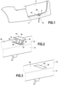
- a cleaning device 1 is illustrated in the figures in its preferred application, namely in a reversing camera system arranged at the rear of the vehicle, in the vicinity of a rear bumper 2 arranged transversely in particular under a rear trunk door 4, as can be seen in the Figure 1
- the device comprises in particular a camera 6 and a cleaning head 8, as well as translational drive means 10 capable of generating a relative movement of the camera with respect to the cleaning head, between an active shooting position (visible on the Figure 2 ), where the camera is clear of the vehicle structure to take shots of the road scene behind the vehicle, and a passive position (visible on the figures 3 And 4 ) where the camera is retracted into the structure of the vehicle, opposite the cleaning head which remains fixed in this same vehicle structure.
- the camera 6 forms means for shooting a road scene located indifferently around the vehicle, and advantageously behind the vehicle. to provide information to the driver when reversing.
- the structural element is a rear bumper shield 2 which comprises a substantially horizontal upper wall 12 arranged directly under the rear trunk door, and a substantially vertical front wall 14 which extends the upper wall downwards.
- the shield has in this context an opening 16 for communication between the housing and the exterior of the shield, so that the camera can pass through this opening to take an active shooting position and then return to its passive position, retracted into the shield.
- This opening 16 is made, in the case illustrated in the figures and as is notably visible on the Figure 2 , in the upper wall 12 of the shield, by cutting it out.
- the opening has a substantially rectangular shape, the dimensions of which are substantially greater than the dimensions of a housing 18 inside which the camera is housed, so as to allow the passage of this camera through the opening.
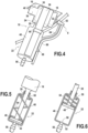
- the housing 18 is part of the drive means 10 of the camera. It is mounted at the end of a rod 20, set in motion by means of an actuator 22 which forms with the rod and the housing said drive means.
- the housing has a cube shape connected on a first face 24 to the rod, and of which a second face, opposite the first face and therefore to the rod, carries a cover 28 extending substantially perpendicularly, at least in two directions, the second face.
- the housing houses a camera lens 30 which has a lens 32 opening onto a third face 34 of the housing perpendicular to the first and second faces, and which should be cleaned at a given periodicity, or after each use of the reversing camera.
- the housing also comprises a guide lug 36, which originates in the excess thickness of a fourth face 38 of the housing and which extends parallel to the rod 20 at a distance from the latter.
- the guide lug has a rectangular section, it being understood that it could be of a different shape.
- the camera is shown in the passive shooting position, retracted inside the shield, seen from outside the vehicle. In this position, it can be seen that the cover 28 closes the opening 16 made in the shield 2. It is indeed interesting that this cover provides a watertight closure of the shield so as to prevent rainwater in particular from penetrating into the shield.
- the cover having dimensions substantially equal to those of the opening, sealing gaskets are provided (not visible in the figures) on the internal face 40 of the cover facing the shield, and provision is made to form in the upper wall of the shield at the edges delimiting this opening, over the entire periphery of the latter, an extension of the edges towards the inside of the opening and set back from the external face of the upper wall to form a bearing surface for the cover, so that the external face 42 of the cover is flush with the external face 44 of the upper wall of the shield in the passive shooting position.
- the drive means 10 comprise the housing 18 in which the camera is housed, so that the relative movement between the camera and the cleaning head is achieved by the movement of the camera.
- the drive means comprise, in addition to the housing, the rod 20 connected to the housing and the actuator 22.
- the rod extends along a translation axis substantially perpendicular to the plane in which the opening in the upper wall of the shield extends, so that the movement of the camera through the opening is not hindered.
- the rod is fixed at a first end to the housing housing the camera so as to be integral with the movement of the camera, and it is fixed at its second end to the actuator, which drives it in substantially vertical translational movements. This generates corresponding vertical movements of the housing and the camera.
- the actuator of the translational drive means is capable of controlling the translation of the camera away from and towards the retracted position in which the lens is opposite the cleaning head.
- the drive means are hydraulic.
- the actuator 22 comprises a casing 46 forming a chamber in which a piston 48 secured to the second end of the rod is capable of sliding, under the effect of pressure differences created by the presence of hydraulic fluid. It is understood that the piston is capable of sliding under the effect of this pressure between a first and a second end position, one corresponding to the passive, retracted shooting position of the camera and the other corresponding to the active shooting position of the camera.
- the chamber is delimited by a hollow cylinder, formed by a circular wall and delimited longitudinally by a first so-called proximal wall 50, facing the camera, and by a second so-called distal wall 52.
- the proximal wall is pierced in its center to allow passage to the rod which connects the housing housing the camera to the piston of the actuator housed inside the chamber. Sealing means are provided between this opening in the proximal wall and the rod to prevent leakage of liquid present in the chamber.
- the piston 48 is housed in the chamber and it has a disc shape with dimensions complementary to those of the circular wall, slightly smaller to allow it to slide in the chamber without, however, liquid being able to circulate between the piston and the circular wall.
- a spring 54 of the spiral spring type, is disposed between the proximal wall 50 and the face of the piston facing this proximal wall, wound around the rod. The spring is stressed so that it tends to push the piston towards the distal wall 52 when no fluid is otherwise exerting pressure on the piston.
- a pipe 56 called the chamber fluid supply pipe, is connected to the actuator chamber, at an orifice 58 made in the distal wall, so that the fluid which is injected into this pipe opens into the chamber between the distal wall and the piston by pushing the piston towards the proximal wall. It is understood that in the illustrated embodiment, the fluid is evacuated through the same orifice as that through which the supply takes place.
- the external surface of the actuator casing carries a loop 60 inside which the guide tab 36 secured to the housing 18 is able to slide.
- the guidance of the housing and the camera, by both the rod and the guide leg, ensures an exclusively sliding movement of the housing relative to the actuator, preventing the housing from rotating on itself during its movement, so that the lens remains correctly oriented relative to the road scene for shooting and relative to the cleaning head.
- the cleaning head 8 has been made visible, which comprises at least one spray nozzle 62 of cleaning liquid, facing the camera when the latter is in the retracted position.
- the cleaning head has a fixed position relative to the structure of the vehicle, housed inside the rear bumper shield when the application of the device is the cleaning of a reversing camera.
- the cleaning head is mounted at the end of a support arm 64 connected at its other end to the casing of the actuator 22, and the support arm extends on the one hand transversely away from the axis of movement of the camera so as not to hinder it, and on the other hand vertically to position the head opposite the lens of the camera when the camera is in the retracted position.
- the support arm is connected to a fixed point other than the actuator housing, and for example directly to the structure of the shield. It is understood that it is important for the cleaning head to maintain a fixed position during movements of the camera, regardless of where it is fixed. However, it should be noted that in the example illustrated, the chain of dimensions corresponding to the relative positioning of the liquid spray nozzles with respect to the lens to be cleaned is reduced, due to the fixing of the head directly to the actuator housing.
- a hydraulic supply pipe 66 is connected to the cleaning head for supplying cleaning liquid.
- This supply pipe connects the cleaning head to a cleaning liquid reservoir provided elsewhere.
- the cleaning head has an internal conduit, not visible in the figures, for conducting the liquid exiting the supply pipe to the spray nozzles. It could be advantageous to provide the same liquid reservoir for performing the function of hydraulic supply to the actuator chamber and for supplying liquid for cleaning the lens via the passage through the cleaning head.
- a control module determines when liquid must be conveyed to the head, and in what proportions. In particular, the control module will be able to establish an instruction to start the cleaning head when, on the one hand, the camera is in the retracted position in the rear bumper, and when, on the other hand, the cyclic cleaning conditions are respected.
- the supply pipe is here blocked in a hook 68 secured to the casing of the actuator 22, and it is shaped to follow the curvature of the support arm.
- the cleaning device of the invention in a passive position, in particular with reference to the Figures 4 and 5 .
- the camera and the cleaning head are housed inside the vehicle structure.
- the camera has been brought in front of the cleaning head, which has remained fixed inside the shield, and it is then possible, under the effect of an appropriate control instruction, to carry out the cleaning of the camera.
- the spring housed inside the chamber pushes the piston into a first extreme position, in which the piston is closest to the distal end wall.
- the piston In this first extreme position, the piston is as far as possible from the upper wall of the bumper shield through which the camera is able to pass, and therefore the camera, made integral with the movement of the piston by means of the rod and the housing, is also set back from this upper wall, in a position such that the lens is opposite the spray nozzles of the cleaning head.
- the passive shooting position of the camera, retracted into the structural element of the vehicle, is stable since the fluid injected into the chamber, via the orifice made in the distal wall, does not generate sufficient pressure to cause the piston to move against the return force of the spring. And it can be observed that this passive shooting position does not automatically generate cleaning of the lens, for several reasons including the possibility that cleaning has been carried out previously without the camera having been made active in the meantime, or the possibility that cleaning was carried out several camera movement cycles ago while remaining below the determined threshold of number of cycles from which cleaning must be carried out.
- the piston tends to return to its initial position and when the shot is taken, the control module generates an instruction to cut off the supply of fluid to the chamber so that the piston is pushed back against the distal wall, ejecting the fluid out of the chamber through the orifice, in the opposite direction to the supply direction.
- the return of the piston towards the distal wall generates the simultaneous movement of the camera towards the inside of the structural element, and when the piston is in the first extreme position, substantially against the distal wall, the camera lens is opposite the cleaning head.
- the control module can then generate an instruction to supply cleaning liquid to the cleaning head.
- the cleaning operation may not be systematic in order to save cleaning liquid in particular. Cleaning may advantageously be controlled under the dual condition of the camera being in the passive shooting position and a previously defined cleaning periodicity coming to an end.
Landscapes
- Engineering & Computer Science (AREA)
- Mechanical Engineering (AREA)
- Water Supply & Treatment (AREA)
- Studio Devices (AREA)
- Cleaning By Liquid Or Steam (AREA)
- Closed-Circuit Television Systems (AREA)
- Camera Bodies And Camera Details Or Accessories (AREA)
Applications Claiming Priority (2)
| Application Number | Priority Date | Filing Date | Title |
|---|---|---|---|
| FR1550513A FR3031919B1 (fr) | 2015-01-22 | 2015-01-22 | Dispositif de nettoyage d'une camera d'aide a la conduite d'un vehicule automobile |
| PCT/EP2015/080331 WO2016116231A1 (fr) | 2015-01-22 | 2015-12-17 | Dispositif de nettoyage d'une camera d'aide a la conduite d'un vehicule automobile |
Publications (2)
| Publication Number | Publication Date |
|---|---|
| EP3247595A1 EP3247595A1 (fr) | 2017-11-29 |
| EP3247595B1 true EP3247595B1 (fr) | 2025-03-19 |
Family
ID=52692941
Family Applications (1)
| Application Number | Title | Priority Date | Filing Date |
|---|---|---|---|
| EP15810740.9A Active EP3247595B1 (fr) | 2015-01-22 | 2015-12-17 | Dispositif de nettoyage d'une camera d'aide a la conduite d'un vehicule automobile |
Country Status (6)
| Country | Link |
|---|---|
| US (1) | US11097668B2 (enExample) |
| EP (1) | EP3247595B1 (enExample) |
| JP (1) | JP6713475B2 (enExample) |
| CN (1) | CN107206435B (enExample) |
| FR (1) | FR3031919B1 (enExample) |
| WO (1) | WO2016116231A1 (enExample) |
Families Citing this family (24)
| Publication number | Priority date | Publication date | Assignee | Title |
|---|---|---|---|---|
| US10875482B2 (en) * | 2013-12-10 | 2020-12-29 | Maxon Industries, Inc. | Mounting system for vehicle underride |
| FR3066452B1 (fr) * | 2017-05-19 | 2019-06-07 | Continental Automotive France | Dispositif de vision exterieure pour vehicule, comprenant une camera |
| DE102017121376B4 (de) * | 2017-09-14 | 2021-01-14 | Motherson Innovations Company Limited | Verfahren zum Betreiben eines Kraftfahrzeugs mit zumindest einer Außenkamera sowie Kraftfahrzeug mit zumindest einer Außenkamera |
| CN107986129B (zh) * | 2017-12-08 | 2024-08-02 | 饶宁军 | 一种安全电梯 |
| DE102018121600B4 (de) * | 2018-09-05 | 2021-10-21 | Dr. Ing. H.C. F. Porsche Aktiengesellschaft | Halter für Rückfahrkamera |
| CN110341655B (zh) * | 2019-06-04 | 2021-02-05 | 深圳市速腾聚创科技有限公司 | 车载传感器清洁系统和传感系统 |
| US11293619B2 (en) * | 2019-10-08 | 2022-04-05 | Valeo Vision | Light system, method of forming tunnels of light, a mobile 360° light system, and a method of cleaning the mobile 360° light system |
| US10907802B1 (en) * | 2020-04-23 | 2021-02-02 | Valeo Vision | Mobile 360° light system and method of cleaning the mobile 360° light system |
| FR3102427B1 (fr) * | 2019-10-25 | 2021-12-24 | Cie Plastic Omnium Se | Caméra de recul escamotable dans un becquet mobile |
| US12269437B2 (en) | 2019-12-10 | 2025-04-08 | Nuro, Inc | Sensor cleaning mechanism for an autonomous vehicle |
| US11623616B2 (en) * | 2020-05-08 | 2023-04-11 | Toyota Motor Engineering & Manufacturing North America, Inc. | Vehicles including sprayer assemblies for vehicle bumpers |
| CN115702098A (zh) * | 2020-07-22 | 2023-02-14 | 金泰克斯公司 | 用于镜头清洁的可调导气罩 |
| CN111866355A (zh) * | 2020-08-14 | 2020-10-30 | 中建商品混凝土有限公司 | 一种摄像头防污装置 |
| DE102020134282A1 (de) * | 2020-12-18 | 2022-06-23 | Zf Cv Systems Global Gmbh | Reinigungsvorrichtung, Reinigungs- und Sensorsystem für ein Fahrzeug und Fahrzeug und Verfahren zum Reinigen einer zu reinigenden Oberfläche eines Sensors |
| US11794664B2 (en) * | 2021-07-28 | 2023-10-24 | Clarion Corporation of America | Underbody camera |
| CN113938594A (zh) * | 2021-10-25 | 2022-01-14 | 广州膳智科技有限公司 | 基于物联网的食品安全监控摄像头 |
| CN114251551A (zh) * | 2021-12-07 | 2022-03-29 | 江苏力源电力工程有限公司 | 一种基于智能移动终端的通讯线路巡检系统 |
| CN114289411B (zh) * | 2021-12-17 | 2023-02-28 | 杭州海康汽车软件有限公司 | 摄像机组件 |
| CN115118854B (zh) * | 2022-06-23 | 2024-09-03 | 浙江华智新航科技有限公司 | 一种车载式光学防抖摄像机 |
| CN115767224B (zh) * | 2022-11-25 | 2025-09-19 | 维沃移动通信有限公司 | 摄像头组件及电子设备 |
| DE102023100653B3 (de) | 2023-01-12 | 2024-04-18 | Audi Aktiengesellschaft | Kraftfahrzeug mit einer ausfahrbaren Kamerahalterung |
| DE102023108301A1 (de) * | 2023-03-31 | 2024-10-02 | Motherson Innovations Company Limited | Kamerasystem mit Reinigungseinheit, Fahrzeugkarosserieteil, Fahrzeug und Reinigungsverfahren |
| US12491841B2 (en) | 2023-07-27 | 2025-12-09 | Ford Global Technologies, Llc | Vehicle assembly for cleaning sensor |
| CN118579016A (zh) * | 2024-08-01 | 2024-09-03 | 比亚迪股份有限公司 | 摄像头总成以及车辆 |
Citations (1)
| Publication number | Priority date | Publication date | Assignee | Title |
|---|---|---|---|---|
| KR20110059055A (ko) * | 2009-11-27 | 2011-06-02 | 삼성전기주식회사 | 차량용 후방 카메라 시스템 |
Family Cites Families (22)
| Publication number | Priority date | Publication date | Assignee | Title |
|---|---|---|---|---|
| JPS58140855U (ja) | 1982-03-19 | 1983-09-22 | 自動車機器技術研究組合 | リトラクタブルヘツドランプクリ−ナ |
| JPS60153062U (ja) | 1984-03-19 | 1985-10-12 | 日野車体工業株式会社 | 車両に使用されるテレビ・カメラ装置 |
| JPH05238312A (ja) * | 1992-02-27 | 1993-09-17 | Honda Motor Co Ltd | 車両用周囲監視装置 |
| JPH06270775A (ja) * | 1993-01-21 | 1994-09-27 | Koito Mfg Co Ltd | ヘッドランプウォッシャー |
| JP2003158649A (ja) | 2001-11-21 | 2003-05-30 | Sony Corp | 車載用ビデオカメラ |
| JP2005523200A (ja) * | 2002-04-23 | 2005-08-04 | オートリブ ディヴェロプメント アクチボラゲット | 夜間視界装置 |
| DE10232227A1 (de) * | 2002-07-17 | 2004-01-29 | Valeo Auto-Electric Wischer Und Motoren Gmbh | Kamerasystem |
| JP4299036B2 (ja) * | 2003-03-31 | 2009-07-22 | シャープ株式会社 | 車両用監視装置 |
| JP2006130949A (ja) * | 2004-11-02 | 2006-05-25 | Ichikoh Ind Ltd | 車両用灯具のクリーナ装置 |
| JP5022609B2 (ja) * | 2006-02-27 | 2012-09-12 | 日立オートモティブシステムズ株式会社 | 撮像環境認識装置 |
| DE102008008656A1 (de) * | 2008-02-11 | 2009-08-13 | Huf Hülsbeck & Fürst Gmbh & Co. Kg | Kamerasystem für ein Kraftfahrzeug mit einer Kameraeinheit |
| JP5056919B2 (ja) * | 2009-09-29 | 2012-10-24 | 株式会社デンソー | 車載光学センサカバー及び車載光学センサ装置 |
| US8497907B2 (en) * | 2009-12-11 | 2013-07-30 | Mobility Solutions Innovation Inc. | Off road vehicle vision enhancement system |
| US10432827B2 (en) * | 2011-03-10 | 2019-10-01 | Dlhbowles, Inc. | Integrated automotive system, nozzle assembly and remote control method for cleaning an image sensors exterior or objective lens surface |
| JP6379665B2 (ja) * | 2013-08-12 | 2018-08-29 | 株式会社デンソー | 車載光学センサ洗浄装置 |
| JP2015047900A (ja) * | 2013-08-30 | 2015-03-16 | アスモ株式会社 | 車載光学センサ洗浄装置 |
| JP6417757B2 (ja) * | 2013-09-19 | 2018-11-07 | 株式会社デンソー | 車載光学センサ洗浄装置 |
| US9973663B2 (en) * | 2014-05-15 | 2018-05-15 | GM Global Technology Operations LLC | Systems and methods for self-cleaning camera |
| US9910272B2 (en) * | 2014-06-10 | 2018-03-06 | Ford Global Technologies, Llc | Integrated camera mounting and image window cleaning device |
| DE102014010495B3 (de) * | 2014-07-16 | 2015-12-17 | Kautex Textron Gmbh & Co. Kg | Fahrzeugintegriertes Sicht- und Reinigungssystem |
| FR3027008B1 (fr) * | 2014-10-10 | 2017-12-08 | Valeo Systemes Dessuyage | Dispositif de nettoyage d’une camera d’aide a la conduite d’un vehicule automobile |
| DE102016107380B4 (de) * | 2015-05-20 | 2025-12-11 | Denso Corporation | Anlage zur Reinigung eines fahrzeugeigenen optischen Sensors und Verfahren dafür |
-
2015
- 2015-01-22 FR FR1550513A patent/FR3031919B1/fr active Active
- 2015-12-17 CN CN201580074146.3A patent/CN107206435B/zh not_active Expired - Fee Related
- 2015-12-17 EP EP15810740.9A patent/EP3247595B1/fr active Active
- 2015-12-17 US US15/543,702 patent/US11097668B2/en active Active
- 2015-12-17 WO PCT/EP2015/080331 patent/WO2016116231A1/fr not_active Ceased
- 2015-12-17 JP JP2017538711A patent/JP6713475B2/ja not_active Expired - Fee Related
Patent Citations (1)
| Publication number | Priority date | Publication date | Assignee | Title |
|---|---|---|---|---|
| KR20110059055A (ko) * | 2009-11-27 | 2011-06-02 | 삼성전기주식회사 | 차량용 후방 카메라 시스템 |
Also Published As
| Publication number | Publication date |
|---|---|
| FR3031919B1 (fr) | 2020-01-03 |
| US11097668B2 (en) | 2021-08-24 |
| WO2016116231A1 (fr) | 2016-07-28 |
| US20180001837A1 (en) | 2018-01-04 |
| CN107206435B (zh) | 2020-08-04 |
| FR3031919A1 (fr) | 2016-07-29 |
| JP2018504312A (ja) | 2018-02-15 |
| JP6713475B2 (ja) | 2020-06-24 |
| CN107206435A (zh) | 2017-09-26 |
| EP3247595A1 (fr) | 2017-11-29 |
Similar Documents
| Publication | Publication Date | Title |
|---|---|---|
| EP3247595B1 (fr) | Dispositif de nettoyage d'une camera d'aide a la conduite d'un vehicule automobile | |
| EP3006279B1 (fr) | Dispositif de nettoyage d'une camera d'aide à la conduite d'un véhicule automobile | |
| EP3206920B1 (fr) | Dispositif de prise de vue d'une scène de route pour véhicule automobile | |
| EP3006278B1 (fr) | Dispositif de nettoyage d'une caméra d'aide à la conduite d'un véhicule automobile | |
| FR3056528B1 (fr) | Dispositif de nettoyage d'un capteur optique, systeme d'assistance a la conduite et procede de nettoyage associes | |
| EP2308532B1 (fr) | Dispositif de support de sécurité pour une seringue et ensemble d'un tel dispositif et d'une seringue | |
| FR3066452B1 (fr) | Dispositif de vision exterieure pour vehicule, comprenant une camera | |
| EP3463995A1 (fr) | Systeme de nettoyage d'un capteur optique, ensemble comprenant un tel systeme et vehicule automobile associe | |
| EP3463996A1 (fr) | Systeme de nettoyage d'un capteur optique, ensemble comprenant un tel systeme et vehicule automobile associe | |
| WO2018091635A1 (fr) | Dispositif de protection d'un capteur optique, système d'assistance à la conduite et procédé de nettoyage associés | |
| FR2858280A1 (fr) | Dispositif de vision arriere pour vehicule automobile | |
| FR2826626A1 (fr) | Module d'equipement d'un vehicule automobile | |
| FR2994149A1 (fr) | Dispositif de connexion entre un bras d'essuyage et un balai d'essuyage, comprenant une zone amenagee pour recevoir une pluralite d'orifices de projection | |
| WO2013186503A1 (fr) | Balai d'essuyage a connecteur hydraulique | |
| FR3050158A1 (fr) | Systeme d’essuyage d’un pare-brise de vehicule | |
| WO2020244869A1 (fr) | Dispositif de nettoyage d'une surface vitrée d'un capteur optique pour un véhicule automobile | |
| EP2692598B1 (fr) | Dispositif de connexion entre un bras d'essuyage et un balai d'essuyage | |
| EP3250422A1 (fr) | Vanne de distribution de fluide pour un système de distribution de liquide lave-glace de véhicule | |
| EP1816044B1 (fr) | Dispositif de lavage d'une surface transparente ou réfléchissante, notamment la glace d'un projecteur d'un véhicule automobile | |
| FR3095628A1 (fr) | Module de nettoyage d’un dispositif de protection d’un élément optique, système d’assistance à la conduite, et procédé de nettoyage associés | |
| FR3078936A1 (fr) | Dispositif de nettoyage de véhicule | |
| EP1099610B1 (fr) | Dispositif perfectionné de lavage des surfaces vitrées de véhicules automobiles | |
| FR2661380A1 (fr) | Dispositif lave-glace pour un retroviseur exterieur de vehicule automobile. | |
| FR3085472A1 (fr) | Bouclier anti-emeute comprenant un pulverisateur de fluide anti-agression | |
| EP1466796A1 (fr) | Dispositif escamotable de lavage de la glace de fermeture d'un dispositif d'éclairage et/ou de signalisation pour véhicule automobile |
Legal Events
| Date | Code | Title | Description |
|---|---|---|---|
| STAA | Information on the status of an ep patent application or granted ep patent |
Free format text: STATUS: THE INTERNATIONAL PUBLICATION HAS BEEN MADE |
|
| PUAI | Public reference made under article 153(3) epc to a published international application that has entered the european phase |
Free format text: ORIGINAL CODE: 0009012 |
|
| STAA | Information on the status of an ep patent application or granted ep patent |
Free format text: STATUS: REQUEST FOR EXAMINATION WAS MADE |
|
| 17P | Request for examination filed |
Effective date: 20170619 |
|
| AK | Designated contracting states |
Kind code of ref document: A1 Designated state(s): AL AT BE BG CH CY CZ DE DK EE ES FI FR GB GR HR HU IE IS IT LI LT LU LV MC MK MT NL NO PL PT RO RS SE SI SK SM TR |
|
| AX | Request for extension of the european patent |
Extension state: BA ME |
|
| DAV | Request for validation of the european patent (deleted) | ||
| DAX | Request for extension of the european patent (deleted) | ||
| STAA | Information on the status of an ep patent application or granted ep patent |
Free format text: STATUS: EXAMINATION IS IN PROGRESS |
|
| 17Q | First examination report despatched |
Effective date: 20210624 |
|
| P01 | Opt-out of the competence of the unified patent court (upc) registered |
Effective date: 20230528 |
|
| GRAP | Despatch of communication of intention to grant a patent |
Free format text: ORIGINAL CODE: EPIDOSNIGR1 |
|
| STAA | Information on the status of an ep patent application or granted ep patent |
Free format text: STATUS: GRANT OF PATENT IS INTENDED |
|
| INTG | Intention to grant announced |
Effective date: 20241010 |
|
| GRAS | Grant fee paid |
Free format text: ORIGINAL CODE: EPIDOSNIGR3 |
|
| GRAA | (expected) grant |
Free format text: ORIGINAL CODE: 0009210 |
|
| STAA | Information on the status of an ep patent application or granted ep patent |
Free format text: STATUS: THE PATENT HAS BEEN GRANTED |
|
| AK | Designated contracting states |
Kind code of ref document: B1 Designated state(s): AL AT BE BG CH CY CZ DE DK EE ES FI FR GB GR HR HU IE IS IT LI LT LU LV MC MK MT NL NO PL PT RO RS SE SI SK SM TR |
|
| REG | Reference to a national code |
Ref country code: GB Ref legal event code: FG4D Free format text: NOT ENGLISH |
|
| REG | Reference to a national code |
Ref country code: CH Ref legal event code: EP |
|
| REG | Reference to a national code |
Ref country code: IE Ref legal event code: FG4D Free format text: LANGUAGE OF EP DOCUMENT: FRENCH |
|
| REG | Reference to a national code |
Ref country code: DE Ref legal event code: R096 Ref document number: 602015091254 Country of ref document: DE |
|
| PG25 | Lapsed in a contracting state [announced via postgrant information from national office to epo] |
Ref country code: RS Free format text: LAPSE BECAUSE OF FAILURE TO SUBMIT A TRANSLATION OF THE DESCRIPTION OR TO PAY THE FEE WITHIN THE PRESCRIBED TIME-LIMIT Effective date: 20250619 |
|
| PG25 | Lapsed in a contracting state [announced via postgrant information from national office to epo] |
Ref country code: FI Free format text: LAPSE BECAUSE OF FAILURE TO SUBMIT A TRANSLATION OF THE DESCRIPTION OR TO PAY THE FEE WITHIN THE PRESCRIBED TIME-LIMIT Effective date: 20250319 |
|
| REG | Reference to a national code |
Ref country code: LT Ref legal event code: MG9D |
|
| PG25 | Lapsed in a contracting state [announced via postgrant information from national office to epo] |
Ref country code: NO Free format text: LAPSE BECAUSE OF FAILURE TO SUBMIT A TRANSLATION OF THE DESCRIPTION OR TO PAY THE FEE WITHIN THE PRESCRIBED TIME-LIMIT Effective date: 20250619 |
|
| PG25 | Lapsed in a contracting state [announced via postgrant information from national office to epo] |
Ref country code: HR Free format text: LAPSE BECAUSE OF FAILURE TO SUBMIT A TRANSLATION OF THE DESCRIPTION OR TO PAY THE FEE WITHIN THE PRESCRIBED TIME-LIMIT Effective date: 20250319 |
|
| PG25 | Lapsed in a contracting state [announced via postgrant information from national office to epo] |
Ref country code: LV Free format text: LAPSE BECAUSE OF FAILURE TO SUBMIT A TRANSLATION OF THE DESCRIPTION OR TO PAY THE FEE WITHIN THE PRESCRIBED TIME-LIMIT Effective date: 20250319 |
|
| PG25 | Lapsed in a contracting state [announced via postgrant information from national office to epo] |
Ref country code: GR Free format text: LAPSE BECAUSE OF FAILURE TO SUBMIT A TRANSLATION OF THE DESCRIPTION OR TO PAY THE FEE WITHIN THE PRESCRIBED TIME-LIMIT Effective date: 20250620 Ref country code: BG Free format text: LAPSE BECAUSE OF FAILURE TO SUBMIT A TRANSLATION OF THE DESCRIPTION OR TO PAY THE FEE WITHIN THE PRESCRIBED TIME-LIMIT Effective date: 20250319 |
|
| REG | Reference to a national code |
Ref country code: NL Ref legal event code: MP Effective date: 20250319 |
|
| REG | Reference to a national code |
Ref country code: AT Ref legal event code: MK05 Ref document number: 1776727 Country of ref document: AT Kind code of ref document: T Effective date: 20250319 |
|
| PG25 | Lapsed in a contracting state [announced via postgrant information from national office to epo] |
Ref country code: NL Free format text: LAPSE BECAUSE OF FAILURE TO SUBMIT A TRANSLATION OF THE DESCRIPTION OR TO PAY THE FEE WITHIN THE PRESCRIBED TIME-LIMIT Effective date: 20250319 |
|
| PG25 | Lapsed in a contracting state [announced via postgrant information from national office to epo] |
Ref country code: SE Free format text: LAPSE BECAUSE OF FAILURE TO SUBMIT A TRANSLATION OF THE DESCRIPTION OR TO PAY THE FEE WITHIN THE PRESCRIBED TIME-LIMIT Effective date: 20250319 |
|
| PG25 | Lapsed in a contracting state [announced via postgrant information from national office to epo] |
Ref country code: SM Free format text: LAPSE BECAUSE OF FAILURE TO SUBMIT A TRANSLATION OF THE DESCRIPTION OR TO PAY THE FEE WITHIN THE PRESCRIBED TIME-LIMIT Effective date: 20250319 |
|
| PG25 | Lapsed in a contracting state [announced via postgrant information from national office to epo] |
Ref country code: ES Free format text: LAPSE BECAUSE OF FAILURE TO SUBMIT A TRANSLATION OF THE DESCRIPTION OR TO PAY THE FEE WITHIN THE PRESCRIBED TIME-LIMIT Effective date: 20250319 Ref country code: PT Free format text: LAPSE BECAUSE OF FAILURE TO SUBMIT A TRANSLATION OF THE DESCRIPTION OR TO PAY THE FEE WITHIN THE PRESCRIBED TIME-LIMIT Effective date: 20250721 |
|
| PG25 | Lapsed in a contracting state [announced via postgrant information from national office to epo] |
Ref country code: PL Free format text: LAPSE BECAUSE OF FAILURE TO SUBMIT A TRANSLATION OF THE DESCRIPTION OR TO PAY THE FEE WITHIN THE PRESCRIBED TIME-LIMIT Effective date: 20250319 Ref country code: IT Free format text: LAPSE BECAUSE OF FAILURE TO SUBMIT A TRANSLATION OF THE DESCRIPTION OR TO PAY THE FEE WITHIN THE PRESCRIBED TIME-LIMIT Effective date: 20250319 |
|
| PG25 | Lapsed in a contracting state [announced via postgrant information from national office to epo] |
Ref country code: AT Free format text: LAPSE BECAUSE OF FAILURE TO SUBMIT A TRANSLATION OF THE DESCRIPTION OR TO PAY THE FEE WITHIN THE PRESCRIBED TIME-LIMIT Effective date: 20250319 |
|
| PG25 | Lapsed in a contracting state [announced via postgrant information from national office to epo] |
Ref country code: CZ Free format text: LAPSE BECAUSE OF FAILURE TO SUBMIT A TRANSLATION OF THE DESCRIPTION OR TO PAY THE FEE WITHIN THE PRESCRIBED TIME-LIMIT Effective date: 20250319 Ref country code: EE Free format text: LAPSE BECAUSE OF FAILURE TO SUBMIT A TRANSLATION OF THE DESCRIPTION OR TO PAY THE FEE WITHIN THE PRESCRIBED TIME-LIMIT Effective date: 20250319 |
|
| PG25 | Lapsed in a contracting state [announced via postgrant information from national office to epo] |
Ref country code: RO Free format text: LAPSE BECAUSE OF FAILURE TO SUBMIT A TRANSLATION OF THE DESCRIPTION OR TO PAY THE FEE WITHIN THE PRESCRIBED TIME-LIMIT Effective date: 20250319 |
|
| PG25 | Lapsed in a contracting state [announced via postgrant information from national office to epo] |
Ref country code: SK Free format text: LAPSE BECAUSE OF FAILURE TO SUBMIT A TRANSLATION OF THE DESCRIPTION OR TO PAY THE FEE WITHIN THE PRESCRIBED TIME-LIMIT Effective date: 20250319 |
|
| PG25 | Lapsed in a contracting state [announced via postgrant information from national office to epo] |
Ref country code: IS Free format text: LAPSE BECAUSE OF FAILURE TO SUBMIT A TRANSLATION OF THE DESCRIPTION OR TO PAY THE FEE WITHIN THE PRESCRIBED TIME-LIMIT Effective date: 20250719 |
|
| PG25 | Lapsed in a contracting state [announced via postgrant information from national office to epo] |
Ref country code: DK Free format text: LAPSE BECAUSE OF FAILURE TO SUBMIT A TRANSLATION OF THE DESCRIPTION OR TO PAY THE FEE WITHIN THE PRESCRIBED TIME-LIMIT Effective date: 20250319 |
|
| PGFP | Annual fee paid to national office [announced via postgrant information from national office to epo] |
Ref country code: FR Payment date: 20251230 Year of fee payment: 11 |
|
| PLBE | No opposition filed within time limit |
Free format text: ORIGINAL CODE: 0009261 |
|
| STAA | Information on the status of an ep patent application or granted ep patent |
Free format text: STATUS: NO OPPOSITION FILED WITHIN TIME LIMIT |