EP3246496A1 - Gleiter für ein rahmenprofil - Google Patents
Gleiter für ein rahmenprofil Download PDFInfo
- Publication number
- EP3246496A1 EP3246496A1 EP17171502.2A EP17171502A EP3246496A1 EP 3246496 A1 EP3246496 A1 EP 3246496A1 EP 17171502 A EP17171502 A EP 17171502A EP 3246496 A1 EP3246496 A1 EP 3246496A1
- Authority
- EP
- European Patent Office
- Prior art keywords
- slider
- frame profile
- holder
- profile
- boom
- Prior art date
- Legal status (The legal status is an assumption and is not a legal conclusion. Google has not performed a legal analysis and makes no representation as to the accuracy of the status listed.)
- Withdrawn
Links
- 230000003014 reinforcing effect Effects 0.000 claims description 5
- 238000003780 insertion Methods 0.000 claims description 2
- 230000037431 insertion Effects 0.000 claims description 2
- 238000010276 construction Methods 0.000 description 3
- 210000004907 gland Anatomy 0.000 description 2
- 241001295925 Gegenes Species 0.000 description 1
- 230000002787 reinforcement Effects 0.000 description 1
Images


Classifications
-
- E—FIXED CONSTRUCTIONS
- E04—BUILDING
- E04H—BUILDINGS OR LIKE STRUCTURES FOR PARTICULAR PURPOSES; SWIMMING OR SPLASH BATHS OR POOLS; MASTS; FENCING; TENTS OR CANOPIES, IN GENERAL
- E04H15/00—Tents or canopies, in general
- E04H15/32—Parts, components, construction details, accessories, interior equipment, specially adapted for tents, e.g. guy-line equipment, skirts, thresholds
- E04H15/34—Supporting means, e.g. frames
- E04H15/44—Supporting means, e.g. frames collapsible, e.g. breakdown type
- E04H15/48—Supporting means, e.g. frames collapsible, e.g. breakdown type foldable, i.e. having pivoted or hinged means
-
- E—FIXED CONSTRUCTIONS
- E04—BUILDING
- E04H—BUILDINGS OR LIKE STRUCTURES FOR PARTICULAR PURPOSES; SWIMMING OR SPLASH BATHS OR POOLS; MASTS; FENCING; TENTS OR CANOPIES, IN GENERAL
- E04H15/00—Tents or canopies, in general
- E04H15/32—Parts, components, construction details, accessories, interior equipment, specially adapted for tents, e.g. guy-line equipment, skirts, thresholds
- E04H15/34—Supporting means, e.g. frames
-
- F—MECHANICAL ENGINEERING; LIGHTING; HEATING; WEAPONS; BLASTING
- F16—ENGINEERING ELEMENTS AND UNITS; GENERAL MEASURES FOR PRODUCING AND MAINTAINING EFFECTIVE FUNCTIONING OF MACHINES OR INSTALLATIONS; THERMAL INSULATION IN GENERAL
- F16B—DEVICES FOR FASTENING OR SECURING CONSTRUCTIONAL ELEMENTS OR MACHINE PARTS TOGETHER, e.g. NAILS, BOLTS, CIRCLIPS, CLAMPS, CLIPS OR WEDGES; JOINTS OR JOINTING
- F16B7/00—Connections of rods or tubes, e.g. of non-circular section, mutually, including resilient connections
- F16B7/04—Clamping or clipping connections
- F16B7/044—Clamping or clipping connections for rods or tubes being in angled relationship
- F16B7/048—Clamping or clipping connections for rods or tubes being in angled relationship for rods or for tubes without using the innerside thereof
- F16B7/0493—Clamping or clipping connections for rods or tubes being in angled relationship for rods or for tubes without using the innerside thereof forming a crossed-over connection
Definitions
- the invention relates to a slider for a frame profile according to the preamble of claim 1.
- the object of the invention is to provide a slider, which allows a flexible and simple construction of roof profiles.
- An inventive slider should be used for a frame profile.
- An inventive frame profile extends here perpendicular to a floor in a proper use in the context of a tent or a wall. For tents this can be fair tents or marquees or the like.
- the wall may, for example, be a trade fair wall or an office wall or the like.
- the slider has a base body with an opening for the frame profile.
- the shape and size of the body is chosen such that the frame profile can slide in the opening.
- the basic body is a tubular or hollow profile.
- the hollow profile has a length of preferably 5 cm to 20 cm.
- the frame profile has a locking pin.
- the locking pin is spring-loaded and cooperates with recesses on the slider such that the slider is held in a defined position.
- the locking pin engages in a recess of the slider and can be pressed into the frame profile to adjust the slider.
- the slider has a boom, wherein the boom has a pivotable and / or fixable holder.
- the holder is designed such that it can be pivoted and fixed via a connecting bolt to the boom.
- the connecting pin is pressed and the holder in pivoted a desired position.
- the connecting bolt sets by releasing the bracket relative to the boom.
- the connecting bolt can each be provided with a through hole, not only to save material, but to allow later connections of accessories or cable glands.
- the main body two booms are preferably arranged, which are each connected to a respective holder.
- the booms are further provided with reinforcing ribs.
- the reinforcing ribs extend from the periphery of the cantilever out into the region between the holder and the main body. As a result, a special strength is achieved.
- the holder is designed such that it comprises a roof profile. It is particularly inventive that gliders were not used in such constructions for the support of roof profiles, since it was assumed that no sufficient strength would be present.
- the bracket and the boom are penetrated by the connecting bolt and are connected to each other.
- a holder contact surface of the holder is pivotally mounted to a cantilever contact surface of the cantilever.
- the support contact surface preferably matches the delivery contact surface in an annular manner. Due to the ring shape, the holder can be easily adjusted relative to the boom and still has enough contact surface for receiving forces.
- the ring shape has an inner diameter of 1 to 1.5 cm and an outer diameter of 2.5 to 4 cm.
- the holder has a receptacle suitable for insertion of the roof profile.
- the image is to be adapted to the size, shape and size of the roof profile.
- the recording should have such a depth, that 1 cm to 4 cm of the roof profile can be inserted into the receptacle. This achieves a special stability.
- the receptacle has essentially half the dimensions of the opening. This results from the fact that the boom and the bracket each half reflect the width of the frame profile.
- a print head spring is present on the base body.
- the print head spring is configured such that it can push down the spring-loaded locking bolt of the frame profile, that is to say can push it into the frame profile, in order to be able to move the base body against the frame profile.
- the push-button spring thus serves to actuate or unlock one of a plurality of spring-mounted locking bolts, which are mounted in corresponding bores not shown in detail in the frame profile.
- the main body of the slider has a recess into which a respective locking bolt can be received when the main body of the slider slides along the frame profile.
- The has a disc-like pressure surface, which allows easy operation by a finger. In this way it is prevented that pinching of skin or fingertips can happen.
- the slider according to the invention acts like a connecting joint, in which case the slider, the swivel joint, the connecting bolt, and the push-button spring practically form a unit.
- the connecting joint or the slider connects the pillar in the form of the frame profile with the roof profiles.
- the main body is characterized by the fact that both the joint half of the boom and the holder have large contact areas and positive engagement, and thus can better absorb the forces acting on the slider. Transverse forces are over the large contact surfaces taken up between the elements but also on the cylindrical surface of the body or bearing. The residual forces are derived via reinforcement ribs and direct contact, optimally to the guide sleeve or the main body of the slider. This positive connection also allows an improvement of the leadership of the joint elements to each other.
- the entire unit consisting of the frame profile or the supporting leg, the glider and the roof profile is not only more stable but also more precise.
- the basic design of the entire slider also aims at a simple tool-free assembly and disassembly, but unintentional disassembly during use is prevented because the connecting pin was designed purely for positive engagement and clamping and not on mechanical forces caused by the assembly and disassembly of the tent system occur. It is, so to speak, functionally decoupled from the tent movement.
- the connecting bolt is not the axle on the joint: the connecting bolt rests in the bracket and the boom and couples the slider with the roof profile.
- the roof profile was optimized in cross-section but also in production.
- the new cross-section optimally absorbs vertical and horizontal forces, which are dissipated into the joint via the high positive engagement.
- the roof profile for example, a ribbing for stiffening.
- a slider 1 for a frame profile 6 has a base body 2, which is provided with an opening 14 for the frame profile 6, so that the slider 1 or the base body 2 can slide along the frame profile 6.
- two arms 15 and 16 are preferably arranged, which are each connected to a holder 3 and 4, respectively.
- the bracket 3 and the boom 15 are penetrated via a connecting pin 17 and connected to each other.
- the holder 4 and the boom 16 are penetrated via a connecting pin 18 and connected to each other.
- the booms 15 and 16 are further provided with reinforcing ribs 11.
- the connecting pins 17 and 18 may each be provided with a through hole 13, not only to save material, but to allow subsequent connections of accessories or cable glands.
- the brackets 3 and 4 are pivotally and / or fixably connected to the arms 15 and 16, wherein a support contact surface 19 of the bracket 3 to a boom contact surface 21 of the boom 15 and a mounting contact surface (not shown in detail) of the bracket 4 to a boom contact surface 22 of Jib 16 is pivotable. Both the mounting contact surfaces 19 and the boom contact surfaces 21 and 22 are preferably annular.
- the brackets 3 and 4 each have a receptacle 23 and 24, which are suitable to receive a respective roof profile 7.
- the receptacles 23 and 24 have substantially half of the dimensions of the opening 14 of the base body 2.
- a cable feedthrough may be possible via one or more roof profiles 7, since the roof profile 7 is preferably designed as a hollow profile.
- the roof profile 7 has a through hole 27 through which the roof profile 7 is held in its receptacle 23 and 24 by the connecting pin 17 and 18 respectively.
- a push-button spring 5 is also present, which is guided in a longitudinal bore 28 in the base body 2 of the slider 1 along the base body 2 and preferably parallel to the frame profile 6.
- the push-button spring 5 is used for actuating or unlocking one of a plurality of spring-mounted locking bolt 8, which are mounted in respective holes not shown in detail in the frame section 6.
- the main body 2 of the slider 1 has a recess 25, in each of which a locking pin 8 can be accommodated when the main body 2 of the slider 1 slides along the frame profile 6.
- the push-button spring 5 covers with a disc-like pressure surface 26 the locking pin 8 so that pinching of skin or fingertips is prevented. Furthermore, a perceived exporting force reduces, since instead of the small locking bolt 8 on the pressure surface 26 of the push-button spring 5 is pressed, wherein a push button 29 on a frame profile 6 facing side of the pressure surface 26 engages with the locking pin 8 in operative connection.
- the slider 1 or its base 2 must be moved along the frame profile 6.
- the base body 2 passes over the corresponding locking bolt 8 in the frame profile 6 until it enters the recess 25 in the base body 2.
- the roof profiles 7 can be pivoted to their desired position. This is done via a rotation of the brackets 3 and 4 to the arms 15 and 16, respectively.
- the roof profiles 7 must first be pivoted back to their starting position parallel to the frame profile 6. Then the base body 2 or the recess 25 must be brought out of engagement with the locking pin 8 of the frame profile 6.
- the push button spring 5 is pressed on the pressure surface 26, whereby the push button 29 turn the locking pin 8 against the pressure of a spring not shown in detail in the frame profile 6 inwardly, i. in the direction of an interior of the frame profile 6 presses.
Landscapes
- Engineering & Computer Science (AREA)
- Architecture (AREA)
- Civil Engineering (AREA)
- Structural Engineering (AREA)
- Tents Or Canopies (AREA)
Abstract
Bei einem Gleiter für ein Rahmenprofil (6) mit einer Öffnung (14) für das Rahmenprofil (6), wobei das Rahmenprofil (6) einen Arretierbolzen (8) aufweist, und einem Ausleger (15, 16), wobei der Ausleger (15, 16) eine schwenkbare und/oder festlegbare Halterung (3, 4) aufweist, soll die Halterung (3, 4) ein Dachprofil (7) umfassen.
Description
- Die Erfindung betrifft einen Gleiter für ein Rahmenprofil nach dem Oberbegriff des Anspruchs 1.
- Aus dem Stand der Technik ist bekannt, das Dachprofile fest an einem Bodenprofil befestigt werden, um eine notwendige Festigkeit der Konstruktion zu erreichen. In diesem Zusammenhang wird auf die
DE 88 07 754 U1 hingewiesen. - Aufgabe der Erfindung ist es einen Gleiter zur Verfügung zu stellen, welcher einen flexiblen und einfachen Aufbau von Dachprofilen ermöglicht.
- Zur Lösung der Aufgabe führen die Merkmale nach dem Anspruch 1. Vorteilhafte Ausgestaltungen sind in den Unteransprüchen beschrieben.
- Ein erfindungsgemässer Gleiter soll für ein Rahmenprofil zum Einsatz kommen. Ein erfindungsgemässes Rahmenprofil erstreckt sich hier senkrecht zu einem Boden bei einem ordnungsgemässen Einsatz im Rahmen eines Zeltes oder einer Wandung. Bei Zelten kann es sich hierbei um Messezelte oder Festzelte oder dergleichen handeln. Bei der Wandung kann es sich beispielsweise um Messewand oder eine Bürowand oder dergleichen handeln.
- Der Gleiter weist einen Grundkörper mit einer Öffnung für das Rahmenprofil auf. Die Form und Grösse der Grundkörpers ist derart gewählt, dass das Rahmenprofil in der Öffnung gleiten kann. Dabei ist der Grundkörper ein Rohr- oder Hohlprofil. Das Hohlprofil weist eine Länge von bevorzugt 5 cm bis 20 cm auf.
- Das Rahmenprofil weist einen Arretierbolzen auf. Der Arretierbolzen ist federgelagert und wirkt mit Ausnehmungen an dem Gleiter derart zusammen, dass der Gleiter an einer definierten Position gehalten wird. Dazu greift der Arretierbolzen in eine Ausnehmung des Gleiters und kann in das Rahmenprofil hineingedrückt werden, um den Gleiter zu verstellen.
- Der Gleiter weist einen Ausleger auf, wobei der Ausleger eine schwenkbare und/oder festlegbare Halterung aufweist. Die Halterung ist derart gestaltet, dass sie über einen Verbindungsbolzen zu dem Ausleger verschwenkt und festgelegt werden kann. Dazu wird der Verbindungsbolzen gedrückt und die Halterung in eine gewünschte Position geschwenkt. Anschliessend setzt der Verbindungsbolzen durch Loslassen die Halterung gegenüber dem Ausleger fest. Der Verbindungsbolzen können mit jeweils einem Durchgangsloch versehen sein, nicht nur um Material zu sparen, sondern um spätere Anbindungen von Zubehör oder Kabeldurchführungen zu ermöglichen.
- An dem Grundkörper sind bevorzugt zwei Ausleger angeordnet, welche jeweils mit je einer eigenen Halterung verbindbar sind. Die Ausleger sind ferner mit Verstärkungsrippen versehen. Die Verstärkungsrippen erstrecken sich dabei aus dem Umfang des Auslegers hinaus in den Bereich zwischen der Halterung und dem Grundkörper. Dadurch wird eine besondere Festigkeit erreicht.
- Erfindungsgemäss ist die Halterung derart ausgeführt, dass sie ein Dachprofil umfasst. Hierbei ist besonders erfinderisch, dass Gleiter in solchen Konstruktionen nicht für die Halterung von Dachprofilen genutzt wurden, da man davon ausging, dass keine ausreichende Festigkeit vorhanden sein würde.
- Die Halterung und der Ausleger werden durch den Verbindungsbolzen durchgriffen und sind so miteinander verbunden.
- Ausserdem ist eine Halterungskontaktfläche der Halterung zu einer Auslegerkontaktfläche des Auslegers verschwenkbar angeordnet. Das bedeutet, dass die Halterungskontaktfläche mit der Auslegekontaktfläche bevorzugt ringförmig übereinstimmt. Aufgrund der Ringform kann die Halterung einfacher gegenüber dem Ausleger verstellt werden und weist trotzdem genug Kontaktfläche zur Aufnahme von Kräften auf. Bevorzugt weist die Ringform einen inneren Durchmesser von 1 bis 1,5 cm und einen äusseren Durchmesser von 2,5 bis 4 cm auf.
- Die Halterung weist eine Aufnahme auf, geeignet zum Einschub des Dachprofils. Dazu ist die Aufnahme an die Ausmasse, Form und Grösse des Dachprofils anzupassen. Die Aufnahme soll dabei eine solche Tiefe aufweisen, dass 1 cm bis 4 cm des Dachprofils in die Aufnahme eingeschoben werden können. Dadurch wird eine besondere Stabilität erreicht.
- Die Aufnahme weist im Wesentlichen die Hälfte der Ausmasse der Öffnung auf. Dies ergibt sich aus dem Umstand, dass der Ausleger und die Halterung jeweils zur Hälfte die Breite des Rahmenprofils wiedergeben.
- Weiter ist eine Druckkopffeder an dem Grundkörper vorhanden. Die Druckkopffeder ist derart ausgestaltet, dass sie den federgelagerten Arretierbolzens des Rahmenprofils runterdrücken, das heisst in das Rahmenprofil hineindrücken kann, um den Grundkörper an dem Rahmenprofil weiterbewegen zu können.
- Die Druckknopffeder dient also der Betätigung bzw. Entriegelung eines von mehreren federgelagerten Arretierbolzens, welche in entsprechenden nicht näher gezeigten Bohrungen in dem Rahmenprofil gelagert sind. Der Grundkörper des Gleiters weist eine Aussparung auf, in welche jeweils ein Arretierbolzen aufgenommen werden kann, wenn der Grundkörper des Gleiters an dem Rahmenprofil entlanggleitet. Die weist eine scheibenartigen Druckfläche auf, die eine einfache Betätigung durch einen Finger ermöglicht. Auf diese Weis wird verhindert, dass ein Einklemmen von Haut oder Fingerkuppen geschehen kann.
- Der erfindungsgemässe Gleiter wirkt wie Verbindungsgelenk, wobei hier der Gleiter, das Drehgelenk, der Verbindungsbolzen, und die Druckknopffeder praktisch eine Einheit bilden. Das Verbindungsgelenk bzw der Gleiter verbindet das Standbein in Form des Rahmenprofils mit den Dachprofilen.
- Das Grundkörper zeichnet sich dadurch aus, dass sowohl die Gelenkhälfte des Auslegers als auch die Halterung über grosse Kontaktbereiche und Formschluss verfügen, und somit die Kräfte die auf den Gleiter einwirken besser aufnehmen kann. Querkräfte werden über die grosse Kontaktflächen zwischen den Elementen aber auch über die Zylinderfläche des Grundkörpers bzw Lagers aufgenommen. Die Restkräfte werden über Verstärkungsrippen und direkten Kontakt, optimal an die Führungshülse bzw den Grundkörper des Gleiters abgeleitet. Dieser Formschluss ermöglicht auch eine Verbesserung der Führung der Gelenkelemente zueinander.
- Dadurch wir die gesamte Einheit, bestehend aus dem Rahmenprofil bzw. dem Standbein, dem Gleiter und dem Dachprofil nicht nur stabiler sondern auch präziser geführt. Die grundsätzliche Konzeption des gesamten Gleiters zielt auch auf eine einfache werkzeuglose Montage und Demontage ab, jedoch wird eine unabsichtliche Demontage während der Benutzung unterbunden, da der Verbindungsbolzen rein auf Formschluss und Klemmung ausgelegt wurde und nicht auf mechanische Kräfte, welche durch den Auf- und Abbau des Zeltsystems auftreten. Er ist sozusagen funktional zur Zeltbewegung entkoppelt.
- Der Verbindungsbolzen ist nicht wie bei vielen Produkten die Achse am Gelenk: Der Verbindungsbolzen ruht in Halterung und Ausleger und koppelt den Gleiter mit dem Dachprofil.
- Das Dachprofil wurde im Querschnitt aber auch in der Herstellung optimiert. Der neue Querschnitt nimmt optimal Vertikal- und Horziontalkräfte auf, die über den hohen Formschluss in das Gelenk abgeführt werden. Dazu weist das Dachprofil beispielsweise eine Verrippung zur Versteifung auf.
- Weitere Vorteile, Merkmale und Einzelheiten der Erfindung ergeben sich aus der nachfolgenden Beschreibung bevorzugter Ausführungsbeispiele sowie anhand der Zeichnungen; diese zeigen in
- Figur 1
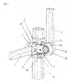
- eine perspektivische Ansicht eines erfindungsgemässen Gleiters für ein Rahmenprofil in Gebrauchslage an einem Rahmenprofil;
- Figur 2
- eine Draufsicht auf den Gleiter an dem Rahmenprofil in
Figur 1 ; - Figur 3
- eine Seitenansicht des Gleiters an dem Rahmenprofil in
Figur 1 ; - Figur 4
- die Seitenansicht des Gleiters an dem Rahmenprofil in
Figur 3 um 90° gegen den Uhrzeigersinn gedreht; - Figur 5
- eine perspektivische Ansicht auf den Gleiter nach
Figur 1 ohne Rahmenprofil; - Figur 6
- eine Explosionsansicht des Gleiters in
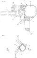
Figur 5 ; - Figur 7
- eine Führungshülse des erfindungsgemässen Gleiters mit einer Druckknopffeder in Gebrauchslage an dem Rahmenprofil;
- Figur 8
- eine Seitenansicht des Gleiters in
Figur 5 ; - Figur 9
- eine Schnittansicht des Gleiters in
Figur 5 entlang der Linie IX - IX; - Figur 10
- eine Schnittansicht des Gleiters in
Figur 5 entlang der Linie X - X; - Figur 11
- eine Draufsicht auf die Führungshülse des Gleiters in
Figur 7 ; - Figur 12
- eine Schnittansicht der Führungshülse des Gleiters in
Figur 11 entlang der Linie XII - XII; und - Figur 13
- perspektivische Ansichten der Druckkopffeder.
- Gemäss den
Figuren 1 bis 13 weist ein Gleiter 1 für ein Rahmenprofil 6 einen Grundkörper 2, welcher mit einer Öffnung 14 für das Rahmenprofil 6 versehen ist, so dass der Gleiter 1 bzw. der Grundkörper 2 an dem Rahmenprofil 6 entlanggleiten kann. - An dem Grundkörper 2 sind bevorzugt zwei Ausleger 15 und 16 angeordnet, welche jeweils mit einer Halterung 3 bzw. 4 verbindbar sind. Die Halterung 3 und der Ausleger 15 sind über einen Verbindungsbolzen 17 durchgriffen und miteinander verbunden. Die Halterung 4 und der Ausleger 16 sind über einen Verbindungsbolzen 18 durchgriffen und miteinander verbunden. Die Ausleger 15 und 16 sind ferner mit Verstärkungsrippen 11 versehen. Die Verbindungsbolzen 17 und 18 können mit jeweils einem Durchgangsloch 13 versehen sein, nicht nur um Material zu sparen, sondern um spätere Anbindungen von Zubehör oder Kabeldurchführungen zu ermöglichen.
- Die Halterungen 3 und 4 sind schwenkbar und/oder festlegbar mit den Auslegern 15 und 16 verbindbar, wobei eine Halterungskontaktfläche 19 der Halterung 3 zu einer Auslegerkontaktfläche 21 des Auslegers 15 bzw. eine Halterungskontaktfläche (nicht näher gezeigt) der Halterung 4 zu einer Auslegerkontaktfläche 22 des Auslegers 16 verschwenkbar ist. Sowohl die Halterungskontaktflächen 19 und die Auslegerkontaktflächen 21 und 22 sind bevorzugt ringförmig ausgebildet.
- Die Halterungen 3 und 4 weisen jeweils eine Aufnahme 23 bzw. 24 auf, welche geeignet sind, um jeweils ein Dachprofil 7 aufzunehmen. Die Aufnahmen 23 und 24 weisen im Wesentlichen die Hälfte der Ausmasse der Öffnung 14 des Grundkörpers 2 auf. Über ein oder mehrere Dachprofile 7 kann ferner eine Kabeldurchführung möglich sein, da das Dachprofil 7 bevorzugt als Hohlprofil ausgebildet ist. Das Dachprofil 7 weist eine Durchgangsbohrung 27 auf, durch welche das Dachprofil 7 in seiner Aufnahme 23 bzw. 24 durch den Verbindungsbolzen 17 bzw. 18 gehalten wird.
- An dem Grundkörper 2 des Gleiters 1 ist weiterhin eine Druckknopffeder 5 vorhanden, welche in einer Längsbohrung 28 in dem Grundkörper 2 des Gleiters 1 entlang des Grundkörpers 2 und bevorzugt parallel zu dem Rahmenprofil 6 geführt ist. Die Druckknopffeder 5 dient der Betätigung bzw. Entriegelung eines von mehreren federgelagerten Arretierbolzens 8, welche in entsprechenden nicht näher gezeigten Bohrungen in dem Rahmenprofil 6 gelagert sind. Der Grundkörper 2 des Gleiters 1 weist eine Aussparung 25 auf, in welche jeweils ein Arretierbolzen 8 aufgenommen werden kann, wenn der Grundkörper 2 des Gleiters 1 an dem Rahmenprofil 6 entlanggleitet.
- Die Druckknopffeder 5 deckt mit einer scheibenartigen Druckfläche 26 den Arretierbolzen 8 so ab, dass ein Einklemmen von Haut oder Fingerkuppen verhindert wird. Ferner wirkt eine gefühlte ausführende Kraft reduziert, da anstatt auf den kleinen Arretierbolzen 8 auf die Druckfläche 26 der Druckknopffeder 5 gedrückt wird, wobei ein Druckknopf 29 auf einer dem Rahmenprofil 6 zugewandten Seite der Druckfläche 26 mit dem Arretierbolzen 8 in Wirkverbindung gelangt.
- Bezugnehmend auf die
Figuren 1 - 13 erklärt sich die Funktionsweise der erfindungsgemässen Vorrichtung folgendermassen: - Der Gleiter 2 und das Rahmenprofil 6 sind Teil beispielsweise eines nicht näher gezeigten faltbaren Zeltes, welches in einem Ausgangszustand zusammengefaltet ist. In diesem Ausgangszustand befindet sich der Gleiter 1 bzw. der Grundkörper 2 bevorzugt in einer unteren Position an dem Rahmenprofil 6. Untere Position bedeutet, dass sich der Grundkörper 2 bevorzugt an einem der Enden des Rahmenprofils 6 befindet. Die Dachprofile 7 in der Ausnahme 23 bzw. 24 sind dann derart positioniert, dass eine Längsseite der Dachprofile 7 parallel zu einer Längsseite des Rahmenprofils 6 verläuft. Der Arretierbolzen 8 des Rahmenprofils 6 befindet sich in Eingriff mit der Aussparung 25 des Grundkörpers 2 des Gleiters 1.
- Soll das Zelt auseinandergefaltet und damit in Gebrauchslage gebracht werden, muss lediglich der Gleiter 1 bzw. sein Grundkörper 2 entlang des Rahmenprofils 6 verschoben werden. An gewünschter Position/Höhe an dem Rahmenprofil 6 überfährt der Grundkörper 2 den entsprechenden Arretierbolzen 8 in dem Rahmenprofil 6, bis dieser in die Aussparung 25 in dem Grundkörper 2 einfährt.
- Anschliessend können die Dachprofile 7 in ihre gewünschte Lage geschwenkt werden. Dies erfolgt über eine Drehung der Halterungen 3 bzw. 4 an den Auslegern 15 bzw. 16.
- Soll das Zelt bzw. der Gleiter 1 in seinen Ausgangszustand gebracht werden, müssen zunächst die Dachprofile 7 wieder in ihre Ausgangsposition parallel zu dem Rahmenprofil 6 geschwenkt werden. Dann muss der Grundkörper 2 bzw. die Aussparung 25 aus ihrem Eingriff mit dem Arretierungsbolzen 8 des Rahmenprofils 6 gebracht werden. Dazu wird auf die Druckfläche 26 der Druckknopffeder 5 gedrückt, wodurch der Druckknopf 29 wiederum den Arretierungsbolzen 8 gegen den Druck einer nicht näher gezeigten Feder in dem Rahmenprofil 6 nach innen, d.h. in Richtung eines Inneren des Rahmenprofils 6 drückt.
- Dadurch kann der Grundkörper 2 des Gleiters 2 an dem Rahmenprofil 6 in die gewünschte Richtung verschoben werden.
Bezugszeichenliste 1 Gleiter 34 2 Grundkörper 35 3 Halterung 36 4 Halterung 37 5 Druckknopffeder 38 6 Rahmenprofil 39 7 Dachprofil 40 8 Arretierbolzen 41 9 42 10 43 11 Verstärkungsrippe 44 12 45 13 Durchgangsloch 46 14 Öffnung 47 15 Ausleger 48 16 Ausleger 49 17 Verbindungsbolzen 50 18 Verbindungsbolzen 51 19 Halterungskontaktfläche 52 20 53 21 Auslegerkontaktfläche 54 22 Auslegerkontaktfläche 55 23 Aufnahme 56 24 Aufnahme 57 25 Aussparung 58 26 Druckfläche 59 27 Durchgangsbohrung 60 28 Längsbohrung 61 29 Druckknopf 62 30 63 31 64 32 65 33 66
Claims (7)
- Gleiter für ein Rahmenprofil (6) mit einer Öffnung (14) für das Rahmenprofil (6), wobei das Rahmenprofil (6) einen Arretierbolzen (8) aufweist, und einem Ausleger (15, 16), wobei der Ausleger (15, 16) eine schwenkbare und/oder festlegbare Halterung (3, 4) aufweist,
dadurch gekennzeichnet,
dass die Halterung (3, 4) ein Dachprofil (7) umfasst. - Gleiter nach Anspruch 1, dadurch gekennzeichnet, dass die Halterung (3, 4) und der Ausleger (15, 16) über einen Verbindungsbolzen (17, 18) durchgriffen und verbunden sind.
- Gleiter nach Anspruch 1 oder 2, dadurch gekennzeichnet, dass eine Halterungskontaktfläche (19) der Halterung (3, 4) zu einer Auslegerkontaktfläche (21, 22) des Auslegers (15, 16) verschwenkbar ist.
- Gleiter nach einem der vorigen Ansprüche, dadurch gekennzeichnet, dass die Halterung (3, 4) eine Aufnahme (23, 24) aufweist, geeignet zum Einschub des Dachprofils (7).
- Gleiter nach Anspruch 4, dadurch gekennzeichnet, dass die Aufnahme (23, 24) im wesentlichen die Hälfte der Ausmasse der Öffnung (14) aufweist.
- Gleiter nach einem der vorigen Ansprüche, dadurch gekennzeichnet, dass eine Druckkopffeder (5) vorhanden ist, geeignet zum Betätigen des federgelagerten Arretierbolzens (8) des Rahmenprofils (6).
- Gleiter nach einem der vorigen Ansprüche, dadurch gekennzeichnet, dass der Ausleger (15, 16) mit Verstärkungsrippen (11) versehen ist.
Applications Claiming Priority (1)
| Application Number | Priority Date | Filing Date | Title |
|---|---|---|---|
| DE102016109145.6A DE102016109145A1 (de) | 2016-05-18 | 2016-05-18 | Gleiter für ein Rahmenprofil |
Publications (1)
| Publication Number | Publication Date |
|---|---|
| EP3246496A1 true EP3246496A1 (de) | 2017-11-22 |
Family
ID=58745064
Family Applications (1)
| Application Number | Title | Priority Date | Filing Date |
|---|---|---|---|
| EP17171502.2A Withdrawn EP3246496A1 (de) | 2016-05-18 | 2017-05-17 | Gleiter für ein rahmenprofil |
Country Status (2)
| Country | Link |
|---|---|
| EP (1) | EP3246496A1 (de) |
| DE (1) | DE102016109145A1 (de) |
Cited By (1)
| Publication number | Priority date | Publication date | Assignee | Title |
|---|---|---|---|---|
| WO2022129074A1 (en) * | 2020-12-14 | 2022-06-23 | Fyx Bv | Frame with notches |
Citations (4)
| Publication number | Priority date | Publication date | Assignee | Title |
|---|---|---|---|---|
| DE8807754U1 (de) | 1988-06-15 | 1988-08-18 | Engelhorn, Bert | Pavillon für Verkaufs- und Ausstellungszwecke |
| US6951327B1 (en) * | 2003-04-01 | 2005-10-04 | Northpole Limited | Detent-releasing device |
| US20060096631A1 (en) * | 2004-11-05 | 2006-05-11 | Go Papa, Lllp | Corner molding and stop assembly for collapsible shelter |
| US20080087313A1 (en) * | 2006-10-17 | 2008-04-17 | Norstar International, Inc. | Collapsible canopy framework |
Family Cites Families (2)
| Publication number | Priority date | Publication date | Assignee | Title |
|---|---|---|---|---|
| CA2657024A1 (en) * | 2006-07-06 | 2008-01-10 | Hkd International (Hk) Limited | Collapsible canopy support assembly |
| KR200430426Y1 (ko) * | 2006-08-01 | 2006-11-13 | 장정우 | 절첩식 천막후레임의 관절구조 |
-
2016
- 2016-05-18 DE DE102016109145.6A patent/DE102016109145A1/de not_active Withdrawn
-
2017
- 2017-05-17 EP EP17171502.2A patent/EP3246496A1/de not_active Withdrawn
Patent Citations (4)
| Publication number | Priority date | Publication date | Assignee | Title |
|---|---|---|---|---|
| DE8807754U1 (de) | 1988-06-15 | 1988-08-18 | Engelhorn, Bert | Pavillon für Verkaufs- und Ausstellungszwecke |
| US6951327B1 (en) * | 2003-04-01 | 2005-10-04 | Northpole Limited | Detent-releasing device |
| US20060096631A1 (en) * | 2004-11-05 | 2006-05-11 | Go Papa, Lllp | Corner molding and stop assembly for collapsible shelter |
| US20080087313A1 (en) * | 2006-10-17 | 2008-04-17 | Norstar International, Inc. | Collapsible canopy framework |
Cited By (2)
| Publication number | Priority date | Publication date | Assignee | Title |
|---|---|---|---|---|
| WO2022129074A1 (en) * | 2020-12-14 | 2022-06-23 | Fyx Bv | Frame with notches |
| BE1028881B1 (nl) * | 2020-12-14 | 2022-07-12 | Fyx Bv | Frame voorzien van uitsparingen |
Also Published As
| Publication number | Publication date |
|---|---|
| DE102016109145A1 (de) | 2017-11-23 |
Similar Documents
| Publication | Publication Date | Title |
|---|---|---|
| EP3233218B1 (de) | Rahmenkonstruktion für ein minitrampolin | |
| EP0964976A1 (de) | Auszugsleiter | |
| DE19717077B4 (de) | Höhenverstellbare Armlehne, insbesondere für einen Bürostuhl | |
| DE2753736A1 (de) | Vorrichtung zur verbindung zweier teile, insbesondere beim moebelbau | |
| EP2364685A2 (de) | Bett, insbesondere Kranken- und/oder Pflegebett | |
| DE8321916U1 (de) | Blockierbare hubvorrichtung zum stufenlosen verstellen von stuhlsitzen, tischplatten oder aehnlichen moebelteilen | |
| EP3156025A1 (de) | Hubbühne | |
| EP3246496A1 (de) | Gleiter für ein rahmenprofil | |
| DE102017127700A1 (de) | Hubaggregat | |
| DE102014118410B4 (de) | Schirmhalteeinrichtung und Sonnen- und/oder Regenschutz | |
| DE2156392A1 (de) | Bauelement für auf Biegung belastete Masten, insb. für Aufzug-, Kran- und Antennenmasten | |
| DE29911334U1 (de) | Zusammenklappvorrichtung für Golfwagen | |
| DE102017117655A1 (de) | Zweiradständer | |
| EP2640557B1 (de) | Arbeitstisch, insbesondere für den werkstattbereich | |
| DE19636959C2 (de) | Stütze, insbesondere als Montagehilfe für Bauzwecke | |
| DE19912050A1 (de) | Montagegerüst mit einer in der Höhe verstellbaren Bühne | |
| DE20109671U1 (de) | Verriegelung eines Trennwandelementes sowie ein Trennwandelement mit einer solchen Vorrichtung | |
| EP0559622B1 (de) | Zusammenlegbares Gestell zur Aufnahme einer Hängematte | |
| EP1707173A1 (de) | Beinstütze und Rollstuhl mit Beinstützen | |
| DE10114359A1 (de) | Mobile Fördereinrichtung mit Verteilermast und begehbaren Pritschen | |
| DE102021113154B4 (de) | Toilettensitzerhöhung | |
| DE3510707A1 (de) | Bettseitenteil aus holz- und/oder kunststoff | |
| EP3305589A1 (de) | Ladebordwand mit sturzsicherung | |
| DE1430713A1 (de) | Sitz in Metallrohrkonstruktion,mit verstellbarer und klappbarer Rueckenlehne,insbesondere fuer Kraftwagen | |
| CH658776A5 (de) | Tisch. |
Legal Events
| Date | Code | Title | Description |
|---|---|---|---|
| PUAI | Public reference made under article 153(3) epc to a published international application that has entered the european phase |
Free format text: ORIGINAL CODE: 0009012 |
|
| AK | Designated contracting states |
Kind code of ref document: A1 Designated state(s): AL AT BE BG CH CY CZ DE DK EE ES FI FR GB GR HR HU IE IS IT LI LT LU LV MC MK MT NL NO PL PT RO RS SE SI SK SM TR |
|
| AX | Request for extension of the european patent |
Extension state: BA ME |
|
| STAA | Information on the status of an ep patent application or granted ep patent |
Free format text: STATUS: THE APPLICATION IS DEEMED TO BE WITHDRAWN |
|
| 18D | Application deemed to be withdrawn |
Effective date: 20180523 |