EP3245844B1 - Élément chauffant en tissu - Google Patents
Élément chauffant en tissu Download PDFInfo
- Publication number
- EP3245844B1 EP3245844B1 EP16709103.2A EP16709103A EP3245844B1 EP 3245844 B1 EP3245844 B1 EP 3245844B1 EP 16709103 A EP16709103 A EP 16709103A EP 3245844 B1 EP3245844 B1 EP 3245844B1
- Authority
- EP
- European Patent Office
- Prior art keywords
- conductive
- fiber layer
- fabric heating
- fibers
- fabric
- Prior art date
- Legal status (The legal status is an assumption and is not a legal conclusion. Google has not performed a legal analysis and makes no representation as to the accuracy of the status listed.)
- Active
Links
- 238000010438 heat treatment Methods 0.000 title claims description 99
- 239000004744 fabric Substances 0.000 title claims description 78
- 239000000835 fiber Substances 0.000 claims description 105
- 239000010410 layer Substances 0.000 claims description 90
- 239000004917 carbon fiber Substances 0.000 claims description 26
- 229920000049 Carbon (fiber) Polymers 0.000 claims description 25
- 239000012790 adhesive layer Substances 0.000 claims description 9
- 239000003365 glass fiber Substances 0.000 claims description 4
- 239000011248 coating agent Substances 0.000 claims description 3
- 238000000576 coating method Methods 0.000 claims description 3
- 239000002245 particle Substances 0.000 claims description 3
- 229920000914 Metallic fiber Polymers 0.000 claims 1
- 239000000463 material Substances 0.000 description 29
- VNWKTOKETHGBQD-UHFFFAOYSA-N methane Chemical compound C VNWKTOKETHGBQD-UHFFFAOYSA-N 0.000 description 17
- 238000004519 manufacturing process Methods 0.000 description 15
- OKTJSMMVPCPJKN-UHFFFAOYSA-N Carbon Chemical compound [C] OKTJSMMVPCPJKN-UHFFFAOYSA-N 0.000 description 11
- RYGMFSIKBFXOCR-UHFFFAOYSA-N Copper Chemical compound [Cu] RYGMFSIKBFXOCR-UHFFFAOYSA-N 0.000 description 11
- 229910052799 carbon Inorganic materials 0.000 description 11
- 239000002131 composite material Substances 0.000 description 11
- 239000010949 copper Substances 0.000 description 11
- 229910052802 copper Inorganic materials 0.000 description 11
- 238000000034 method Methods 0.000 description 8
- 239000000853 adhesive Substances 0.000 description 7
- 230000001070 adhesive effect Effects 0.000 description 7
- 230000009286 beneficial effect Effects 0.000 description 6
- 229920002239 polyacrylonitrile Polymers 0.000 description 6
- 229920001169 thermoplastic Polymers 0.000 description 6
- 239000011230 binding agent Substances 0.000 description 5
- 238000010276 construction Methods 0.000 description 5
- 239000004416 thermosoftening plastic Substances 0.000 description 5
- PXHVJJICTQNCMI-UHFFFAOYSA-N Nickel Chemical compound [Ni] PXHVJJICTQNCMI-UHFFFAOYSA-N 0.000 description 4
- 239000004020 conductor Substances 0.000 description 4
- 230000007547 defect Effects 0.000 description 4
- 239000002648 laminated material Substances 0.000 description 4
- 229910052751 metal Inorganic materials 0.000 description 4
- 239000002184 metal Substances 0.000 description 4
- 229920000139 polyethylene terephthalate Polymers 0.000 description 4
- 239000005020 polyethylene terephthalate Substances 0.000 description 4
- 229910000831 Steel Inorganic materials 0.000 description 3
- NIXOWILDQLNWCW-UHFFFAOYSA-N acrylic acid group Chemical group C(C=C)(=O)O NIXOWILDQLNWCW-UHFFFAOYSA-N 0.000 description 3
- 239000003063 flame retardant Substances 0.000 description 3
- 239000011521 glass Substances 0.000 description 3
- 230000003014 reinforcing effect Effects 0.000 description 3
- 239000010959 steel Substances 0.000 description 3
- 229920001187 thermosetting polymer Polymers 0.000 description 3
- 239000004593 Epoxy Substances 0.000 description 2
- 239000004677 Nylon Substances 0.000 description 2
- 239000004642 Polyimide Substances 0.000 description 2
- PPBRXRYQALVLMV-UHFFFAOYSA-N Styrene Chemical compound C=CC1=CC=CC=C1 PPBRXRYQALVLMV-UHFFFAOYSA-N 0.000 description 2
- 239000004433 Thermoplastic polyurethane Substances 0.000 description 2
- 239000006185 dispersion Substances 0.000 description 2
- 238000010030 laminating Methods 0.000 description 2
- 229910052759 nickel Inorganic materials 0.000 description 2
- 229920001778 nylon Polymers 0.000 description 2
- 238000007747 plating Methods 0.000 description 2
- 229920000728 polyester Polymers 0.000 description 2
- 229920001721 polyimide Polymers 0.000 description 2
- 229920000642 polymer Polymers 0.000 description 2
- 239000004800 polyvinyl chloride Substances 0.000 description 2
- 239000002243 precursor Substances 0.000 description 2
- 239000011343 solid material Substances 0.000 description 2
- 229920002803 thermoplastic polyurethane Polymers 0.000 description 2
- 239000002759 woven fabric Substances 0.000 description 2
- RNFJDJUURJAICM-UHFFFAOYSA-N 2,2,4,4,6,6-hexaphenoxy-1,3,5-triaza-2$l^{5},4$l^{5},6$l^{5}-triphosphacyclohexa-1,3,5-triene Chemical compound N=1P(OC=2C=CC=CC=2)(OC=2C=CC=CC=2)=NP(OC=2C=CC=CC=2)(OC=2C=CC=CC=2)=NP=1(OC=1C=CC=CC=1)OC1=CC=CC=C1 RNFJDJUURJAICM-UHFFFAOYSA-N 0.000 description 1
- 229910001369 Brass Inorganic materials 0.000 description 1
- 239000004952 Polyamide Substances 0.000 description 1
- -1 Polyethylene terephthalate Polymers 0.000 description 1
- 239000004372 Polyvinyl alcohol Substances 0.000 description 1
- 229920000297 Rayon Polymers 0.000 description 1
- BQCADISMDOOEFD-UHFFFAOYSA-N Silver Chemical compound [Ag] BQCADISMDOOEFD-UHFFFAOYSA-N 0.000 description 1
- HCHKCACWOHOZIP-UHFFFAOYSA-N Zinc Chemical compound [Zn] HCHKCACWOHOZIP-UHFFFAOYSA-N 0.000 description 1
- 230000009102 absorption Effects 0.000 description 1
- 238000010521 absorption reaction Methods 0.000 description 1
- 230000001154 acute effect Effects 0.000 description 1
- 239000002313 adhesive film Substances 0.000 description 1
- 230000002009 allergenic effect Effects 0.000 description 1
- 229910052782 aluminium Inorganic materials 0.000 description 1
- XAGFODPZIPBFFR-UHFFFAOYSA-N aluminium Chemical compound [Al] XAGFODPZIPBFFR-UHFFFAOYSA-N 0.000 description 1
- 239000010951 brass Substances 0.000 description 1
- 239000003990 capacitor Substances 0.000 description 1
- 238000007596 consolidation process Methods 0.000 description 1
- 239000004035 construction material Substances 0.000 description 1
- 230000007797 corrosion Effects 0.000 description 1
- 238000005260 corrosion Methods 0.000 description 1
- 238000010586 diagram Methods 0.000 description 1
- 230000009977 dual effect Effects 0.000 description 1
- 229920001971 elastomer Polymers 0.000 description 1
- 238000010292 electrical insulation Methods 0.000 description 1
- 230000005611 electricity Effects 0.000 description 1
- 239000005038 ethylene vinyl acetate Substances 0.000 description 1
- 239000011888 foil Substances 0.000 description 1
- 238000009499 grossing Methods 0.000 description 1
- 238000009413 insulation Methods 0.000 description 1
- 238000002844 melting Methods 0.000 description 1
- 230000008018 melting Effects 0.000 description 1
- 239000013528 metallic particle Substances 0.000 description 1
- 239000000203 mixture Substances 0.000 description 1
- 239000004745 nonwoven fabric Substances 0.000 description 1
- 230000000474 nursing effect Effects 0.000 description 1
- 230000000149 penetrating effect Effects 0.000 description 1
- 229920002647 polyamide Polymers 0.000 description 1
- 229920000098 polyolefin Polymers 0.000 description 1
- 229920002635 polyurethane Polymers 0.000 description 1
- 239000004814 polyurethane Substances 0.000 description 1
- 229920002451 polyvinyl alcohol Polymers 0.000 description 1
- 229940068984 polyvinyl alcohol Drugs 0.000 description 1
- 235000019422 polyvinyl alcohol Nutrition 0.000 description 1
- 229920000915 polyvinyl chloride Polymers 0.000 description 1
- 230000000135 prohibitive effect Effects 0.000 description 1
- 230000001681 protective effect Effects 0.000 description 1
- 239000002964 rayon Substances 0.000 description 1
- 230000001105 regulatory effect Effects 0.000 description 1
- 230000035939 shock Effects 0.000 description 1
- 229910052709 silver Inorganic materials 0.000 description 1
- 239000004332 silver Substances 0.000 description 1
- 239000004753 textile Substances 0.000 description 1
- 239000011345 viscous material Substances 0.000 description 1
- 239000011800 void material Substances 0.000 description 1
- XLYOFNOQVPJJNP-UHFFFAOYSA-N water Substances O XLYOFNOQVPJJNP-UHFFFAOYSA-N 0.000 description 1
- 238000004804 winding Methods 0.000 description 1
- 229910052725 zinc Inorganic materials 0.000 description 1
- 239000011701 zinc Substances 0.000 description 1
Images


Classifications
-
- H—ELECTRICITY
- H05—ELECTRIC TECHNIQUES NOT OTHERWISE PROVIDED FOR
- H05B—ELECTRIC HEATING; ELECTRIC LIGHT SOURCES NOT OTHERWISE PROVIDED FOR; CIRCUIT ARRANGEMENTS FOR ELECTRIC LIGHT SOURCES, IN GENERAL
- H05B1/00—Details of electric heating devices
- H05B1/02—Automatic switching arrangements specially adapted to apparatus ; Control of heating devices
- H05B1/0227—Applications
- H05B1/0252—Domestic applications
- H05B1/0272—For heating of fabrics
-
- H—ELECTRICITY
- H05—ELECTRIC TECHNIQUES NOT OTHERWISE PROVIDED FOR
- H05B—ELECTRIC HEATING; ELECTRIC LIGHT SOURCES NOT OTHERWISE PROVIDED FOR; CIRCUIT ARRANGEMENTS FOR ELECTRIC LIGHT SOURCES, IN GENERAL
- H05B1/00—Details of electric heating devices
- H05B1/02—Automatic switching arrangements specially adapted to apparatus ; Control of heating devices
- H05B1/0227—Applications
- H05B1/023—Industrial applications
- H05B1/0236—Industrial applications for vehicles
- H05B1/0238—For seats
-
- H—ELECTRICITY
- H05—ELECTRIC TECHNIQUES NOT OTHERWISE PROVIDED FOR
- H05B—ELECTRIC HEATING; ELECTRIC LIGHT SOURCES NOT OTHERWISE PROVIDED FOR; CIRCUIT ARRANGEMENTS FOR ELECTRIC LIGHT SOURCES, IN GENERAL
- H05B3/00—Ohmic-resistance heating
- H05B3/02—Details
- H05B3/03—Electrodes
-
- H—ELECTRICITY
- H05—ELECTRIC TECHNIQUES NOT OTHERWISE PROVIDED FOR
- H05B—ELECTRIC HEATING; ELECTRIC LIGHT SOURCES NOT OTHERWISE PROVIDED FOR; CIRCUIT ARRANGEMENTS FOR ELECTRIC LIGHT SOURCES, IN GENERAL
- H05B3/00—Ohmic-resistance heating
- H05B3/10—Heating elements characterised by the composition or nature of the materials or by the arrangement of the conductor
- H05B3/12—Heating elements characterised by the composition or nature of the materials or by the arrangement of the conductor characterised by the composition or nature of the conductive material
- H05B3/14—Heating elements characterised by the composition or nature of the materials or by the arrangement of the conductor characterised by the composition or nature of the conductive material the material being non-metallic
- H05B3/145—Carbon only, e.g. carbon black, graphite
-
- H—ELECTRICITY
- H05—ELECTRIC TECHNIQUES NOT OTHERWISE PROVIDED FOR
- H05B—ELECTRIC HEATING; ELECTRIC LIGHT SOURCES NOT OTHERWISE PROVIDED FOR; CIRCUIT ARRANGEMENTS FOR ELECTRIC LIGHT SOURCES, IN GENERAL
- H05B3/00—Ohmic-resistance heating
- H05B3/20—Heating elements having extended surface area substantially in a two-dimensional plane, e.g. plate-heater
- H05B3/34—Heating elements having extended surface area substantially in a two-dimensional plane, e.g. plate-heater flexible, e.g. heating nets or webs
- H05B3/342—Heating elements having extended surface area substantially in a two-dimensional plane, e.g. plate-heater flexible, e.g. heating nets or webs heaters used in textiles
-
- H—ELECTRICITY
- H05—ELECTRIC TECHNIQUES NOT OTHERWISE PROVIDED FOR
- H05B—ELECTRIC HEATING; ELECTRIC LIGHT SOURCES NOT OTHERWISE PROVIDED FOR; CIRCUIT ARRANGEMENTS FOR ELECTRIC LIGHT SOURCES, IN GENERAL
- H05B2203/00—Aspects relating to Ohmic resistive heating covered by group H05B3/00
- H05B2203/002—Heaters using a particular layout for the resistive material or resistive elements
- H05B2203/005—Heaters using a particular layout for the resistive material or resistive elements using multiple resistive elements or resistive zones isolated from each other
-
- H—ELECTRICITY
- H05—ELECTRIC TECHNIQUES NOT OTHERWISE PROVIDED FOR
- H05B—ELECTRIC HEATING; ELECTRIC LIGHT SOURCES NOT OTHERWISE PROVIDED FOR; CIRCUIT ARRANGEMENTS FOR ELECTRIC LIGHT SOURCES, IN GENERAL
- H05B2203/00—Aspects relating to Ohmic resistive heating covered by group H05B3/00
- H05B2203/011—Heaters using laterally extending conductive material as connecting means
-
- H—ELECTRICITY
- H05—ELECTRIC TECHNIQUES NOT OTHERWISE PROVIDED FOR
- H05B—ELECTRIC HEATING; ELECTRIC LIGHT SOURCES NOT OTHERWISE PROVIDED FOR; CIRCUIT ARRANGEMENTS FOR ELECTRIC LIGHT SOURCES, IN GENERAL
- H05B2203/00—Aspects relating to Ohmic resistive heating covered by group H05B3/00
- H05B2203/026—Heaters specially adapted for floor heating
-
- H—ELECTRICITY
- H05—ELECTRIC TECHNIQUES NOT OTHERWISE PROVIDED FOR
- H05B—ELECTRIC HEATING; ELECTRIC LIGHT SOURCES NOT OTHERWISE PROVIDED FOR; CIRCUIT ARRANGEMENTS FOR ELECTRIC LIGHT SOURCES, IN GENERAL
- H05B2203/00—Aspects relating to Ohmic resistive heating covered by group H05B3/00
- H05B2203/029—Heaters specially adapted for seat warmers
-
- H—ELECTRICITY
- H05—ELECTRIC TECHNIQUES NOT OTHERWISE PROVIDED FOR
- H05B—ELECTRIC HEATING; ELECTRIC LIGHT SOURCES NOT OTHERWISE PROVIDED FOR; CIRCUIT ARRANGEMENTS FOR ELECTRIC LIGHT SOURCES, IN GENERAL
- H05B2203/00—Aspects relating to Ohmic resistive heating covered by group H05B3/00
- H05B2203/036—Heaters specially adapted for garment heating
Definitions
- the present invention relates to a fabric heating element according to claim 1.
- Claims 9 and 11 relate to a fabric heating device and to a fabric heating system respectively.
- One embodiment comprises a fabric heating element including an electrically conductive, non-woven fiber layer having a plurality of conductive fibers collectively having an average length of less than 12mm.
- the fabric heating element also includes at least two conductive strips electrically connected to the fiber layer over a predetermined length, positioned adjacent opposite ends of the fiber layer, and configured to be electrically connected to a power source.
- the fabric heating element also comprises a first adhesive layer adhered to a first side of the fiber layer and a first insulating layer, and a second adhesive layer adhered to a second side of the fiber layer and a second insulating layer.
- a controller is electrically connected to the power supply and the at least two conductive strips.
- the controller is configured to apply a voltage from the power supply to the at least two conductive strips.
- the fiber layer has a uniform electrical resistance in any direction.
- the fiber layer consists of the plurality of conductive carbon fibers, the binder, optionally one or more fire retardants, and optionally a plurality of non-conductive fibers.
- each of the conductive fibers has a length in the range of 6-12mm.
- the fiber layer consists essentially of individual unentangled fibers.
- Heating elements capable of generating and sustaining moderate uniform temperatures over small and large areas are desirable for a variety of applications, ranging from under-floor heating to far infrared (FIR) heating panels for buildings to car seating, electric blankets and clothing for consumer use.
- FIR far infrared
- resistive wire wound in a winding pattern that covers the area to be heated.
- large amounts (e.g. 50 meters) of wire may be used just to cover a single square meter of heated area.
- Loops of resistive wire generally cannot provide desirable uniform temperatures. Wires which are sufficiently fine and closely spaced to provide the required temperatures without "hot spots” are often fragile and easily damaged, with the attendant dangers of fire and electrical shock.
- resistive wires tend to be very thin so that they don't affect the material they are embedded in, as otherwise they may become a flaw or inclusion, which creates structural problems in the heater material after a short period of time.
- Metal sheet and foils are generally suitable only for a limited range of applications in which corrosion resistance is not required, and cost is no object. Generally, such materials cannot feasibly be embedded as an internal heater element.
- Short carbon fibers e.g. fibers of 5 to 20 microns in diameter and between approximately 3 and 9 mm in average fiber length
- Average fiber lengths exceeding 9mm may cause technical difficulties manufacturing with uniformly dispersed carbon fiber throughout, such that irregularity in the resistance value from point to point in the sheet may become problematic.
- the aerial weight may vary between 8 to 60gsm. At aerial weights below 20gsm, non-woven webs can be difficult to handle or are fragile and prone to damage when used in commercial applications as heating elements.
- a fabric heating element that can be embedded in materials in need of heat (e.g. vehicle seat, clothing, etc.), and that is compatible with the material to be heated, thus providing heat from the inside, which is more efficient and faster than providing heat from the outside of the material.
- the device includes a non-metallic porous or perforated fabric heating element comprising an electrically-conductive inner non-continuous fibrous web layer with integrated conductive busbar strips.
- the inner layer is bonded and sandwiched between two outer insulating layers of woven or non-woven material, (e.g. continuous fiber) material.
- the fabric heating element is configured for use as a heated fabric or to be embedded in laminated or solid materials.
- the resulting construction may comprise adhesive extending between the inner and outer layers as well as through the perforations in the inner layer.
- Applications of the device include any item containing such a fabric heating element, such as, for example, apparel or other textiles, and laminated or solid materials.
- An exemplary process for manufacturing the fabric heating element comprising adhesively bonding an electrically-conductive inner non-continuous fibrous web layer between outer insulating layers of woven or non-woven material is described herein.
- the step of bonding the conductive busbar strips to the inner layer may be performed simultaneously with the step of bonding the inner and outer layers together, or prior to the inner/outer layer bonding step.
- the step of bonding the inner layer to the outer layers may comprise the adhesive used for bonding between the layers extending into the perforations in the inner layer.
- An application may comprise a process for embedding the fabric heating element as described herein into a composite structure, the process comprising forming the multi-ply fabric heating element as described herein, and then bonding the fabric heating element into the composite structure.
- Some embodiments may comprise, prior to the embedding step, perforating the fabric heating element, in which case the embedding step may comprise material from the composite structure penetrating the perforations in the fabric heating element.
- the inner electrically conductive layer typically includes fine conductive fibers, typically carbon, dispersed homogeneously in the inner heater element to form a dense network, which convert electricity into heat by the act of resistive heating.
- fine conductive fibers typically carbon
- the inner electrically conductive layer typically includes fine conductive fibers, typically carbon, dispersed homogeneously in the inner heater element to form a dense network, which convert electricity into heat by the act of resistive heating.
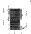
- the fabric heating element 100 shown in Fig. 1 includes six layers of material that form a hybrid construction of busbars and fabric. These layers are shown in the cross-sectional view of Fig. 1 as Item 1, Item 2, Item 3, Item 4, Item 5 and Item 6. Items 1 and 6 are outer insulating and reinforced layers (e.g. woven glass fabric such as aerial weight in the range of 20-100gsm). Items 2 and 5 are adhesive layers (e.g. thermoplastic Polyethylene terephthalate (PET) web having aerial weight of 15gsm). Item 4 is an inner electrically conductive non-woven fiber layer (e.g. carbon fiber having aerial weight of 8-60gsm). Item 3 refers to metallic (e.g. copper) strips having specific dimensions (e.g. 19mm wide and 50microns thick), which act as busbars.
- metallic e.g. copper
- the outer layers comprise an insulating woven or nonwoven fabric (e.g. Items 1 and 6), typically made from a continuous filament.
- a continuous filament or “continuous fiber” when used to characterize yarns, fabrics, or composites may not actually be “continuous” in the strictest definition of the word, and in actuality such fibers or filaments vary from as short as several feet in length to several thousand feet in length. Everything in this wide range is generally called “continuous” because the length of the fibers tends to be orders of magnitude larger than the width or thickness of the raw composite material.
- the inner heating element layer (e.g. Item 4), sandwiched between the outer layers (e.g. Items 1 and 6), includes an electrically conductive material, such as a discontinuous non-woven carbon or carbon/glass fiber web as described herein.
- Bonded to the inner electrically conductive layer are two conductive (e.g. metallic copper) strips (e.g. Item 3) that act as electrical busbars.
- the copper strips ensure uniform current flow throughout the electrical conductive non-woven web, and hence uniform heating due to the resistance. These conductive strips also facilitate connection of power cables to the heater. Although often referred to herein as "copper" strips, it should be understood that the strips are not limited to any particular conductive materials.
- the outer layers e.g. Items 1 and 6) are bonded to the electrically conductive inner layer (e.g. Item 4) using a thermoplastic or thermoset web (e.g. Items 2 and 5) disposed between the inner and outer layers, which results in a hybrid construction heater material.
- a thermoplastic or thermoset web e.g. Items 2 and 5
- exemplary heater elements may be constructed as follows, without limitation to the exemplary material types and features listed:
- the non-woven electrically conductive sheet is formed by wet-laid manufacturing methods from conductive fibers (preferably carbon), non-conductive glass fibers, one or more binder polymers, and optional flame retardants.
- Preferred lengths for the fibers are in the range of 6-12 mm in length.
- Exemplary binder polymers may include: Poly vinyl alcohol, Co-polyester, Cross linked polyester, Acrylic and Polyurethane.
- Exemplary flame retardant binders may include Polyimide and Epoxy. Suitable wet-laying techniques may comprise a state of the art continuous manufacturing process.
- the amount of conductive fiber required depends upon the type of conductive fiber chosen, the voltage and power at which the heating element is to be used, and the physical size/configuration of the heating element, which will determine the current path and density throughout it. Lower voltages and longer current paths require relatively more conductive fiber and lower electrical resistance. Ideal sheets have uniform electrical resistance in any direction. For example, the electrical resistance in the a first direction (e.g. the machine direction) is substantially equal (+/- 5%) to the electrical resistance in a second direction perpendicular to the first direction (e.g. the cross-machine direction).
- Chemitex 20 is a PAN based carbon fiber veil having an areal base weight of 17 g/m2, a styrene soluble binder, a thickness of 0.15mm, a tensile strength in the machine direction and in the cross-machine direction of 60N/15mm, and a resistivity of 5 ohms per square.
- standard commercial carbon fiber sheets e.g. Chemitex carbon fiber sheets
- have been found to be less than ideal for implementing preferred heating element embodiments for various reasons e.g.
- all or a portion of the conductive and/or non-conductive fibers in the non-woven electrically conductive sheet are less than or equal to 12mm in length, such that the average fiber length is less than or equal to 12mm.
- the wet-laid manufacturing method used to manufacture the non-woven electrically conductive sheet does not require additional conductive material (e.g. conductive particles) to attain uniform electrical resistance.
- all of the conductive and/or non-conductive fibers in the non-woven electrically conductive sheet are in the range of 6mm to 12mm in length, with no other additional conductive particles present.
- Conductive fibers which have electrical resistances of 25,000 ohm/cm or lower, in the range of 25 to 15,000 ohm/cm, and which have melting points higher than about 500° C. are beneficial. Conductive fibers which are non-flammable, and are not brittle are also beneficial. It is also beneficial that neither their resistances nor their mechanical properties are significantly affected by temperature variations in the range of 0°-500° C. Other factors such as relatively low water absorption, allergenic properties, and adhesive compatibility may also enter into the selection processes. Suitable fibers include carbon, nickel-coated carbon, silver-coated nylon, and aluminised glass.
- Carbon fibers are beneficial for use in heating elements for consumer applications such as under floor heating mats, since they have all the desired characteristics, are relatively inexpensive, and can be used in small but manageable concentrations to provide the desired heat output at standard household voltages.
- Heating elements for use at low voltages may also be produced. 25 volts, for example, is generally considered to be the maximum shock-proof voltage. In order to protect their patients, most hospitals and nursing homes require that their heating mats operate at this voltage. There are a number of potential applications for battery-powered heating elements, but these elements may operate at 12 volts or less. There has been a long-felt need for a heating element which could maintain temperatures in the range of 50°-180° C. at these voltages.
- Low-voltage heating elements can be manufactured by increasing the concentration of conductive fibers in the element or by using specific types of conductive fibers.
- metal-coated fibers such as nickel-coated carbon are suitable alternatives to carbon fibers for these applications, but carbon fibers and carbon fiber/metal-coated fiber mixtures have also been used successfully.
- Figs. 8A and 8B there are shown two magnified photographs ( FIG. 8B has greater magnification than Fig. 8A ) of a representative portion of an exemplary non-woven fiber sheet that is particularly well-suited for use in connection with the claimed invention.
- the fiber sheet comprises a plurality of individual, substantial straight unentangled fibers, all of which are fall within a specified range of lengths (e.g. 6-12mm).
- a sheet consisting of only individual, unentangled fibers (i.e. each fiber is "unentangled” with any other fiber) throughout the entire sheet is void of defects that can otherwise cause operational issues when the sheet is used practice as described herein.
- Such defects (not shown) to be avoided may include but are not limited to "logs or sticks” (i.e. bundles of fibers whose ends are aligned and thus act as if they are outside the specified range); "ropes” (i.e. fiber assemblages with unaligned ends that are not completely isolated from one another or that are entwined around one another along the axes of the fibers); "fused fibers” (i.e. bundles of fibers fused at the ends or along the fiber length); or “clumps” or “dumbbells” (i.e. assemblages of normal-length fibers ensnared by one or more overly long fibers).
- logs or sticks i.e. bundles of fibers whose ends are aligned and thus act as if they are outside the specified range
- ropes i.e. fiber assemblages with unaligned ends that are not completely isolated from one another or that are entwined around one another along the axes of the fibers
- each individual fiber of the non-woven sheet is desirably in contact with one or more other individual fibers as part of the non-woven structure of the sheet
- ideal contact differs from entanglement in that entanglement typically involves two or more fibers wound around each other along the longitudinal axis of the fibers
- preferred contact comprises straight, unentangled fibers having multiple points of contact with other straight unentangled fibers such that the longitudinal axes of the contacting fibers are at acute or perpendicular angles with one another.
- some embodiments may comprise sheets that have been visually checked (manually or with machine vision) to confirm the absence of defects such as but not limited to those described above, and only sheets consisting essentially of individual, unentangled fibers (i.e. sheets having a defect rate of less than 200 per 100 gram weight of material) may be used. Manufacturing processes for making sheets for use as described herein are therefore preferably designed to provide first quality as a high percentage of throughput.
- PAN Polyacrylonitrile
- Other precursors, such as rayon or pitch base may be used, but PAN is a beneficial choice for performance, consistency and quality for this application.
- Beneficial heater element material characteristics may include:
- Heater element materials that are flexible and can easily be draped or formed into 3D shapes are particularly advantageous. Use of a veil heater element that is not coated or treated, in combination with the other exemplary layers described herein, results in a fabric that includes an uncoated or dry perform that may be infused or impregnated with the material into which the fabric is intended to be later embedded.
- Fabric heating element 100 shown in Fig. 1 may be manufactured in various configurations to be inserted in various applications (e.g. heated clothing, car seats, etc.). Shown in Fig. 2 are top views of two examples of the manufactured fabric heating element 100 in Fig 1 .
- fabric heating element 200 includes a non-perforated fabric layer 206, and busbars 204 and 208.
- fabric heating element 202 includes a perforated fabric layer 212, and busbars 210 and 214.
- electrical wires are connected to the busbars to apply a voltage to the busbars and produce an electrical current flowing through the fabric layers 206 and 212 respectively.
- busbars e.g. closer busbars provide a lower resistance electrical path and therefore produce higher current/temperature
- level of voltage applied to the busbars e.g. higher voltage produces higher current/temperature
- density/shape of perforations e.g. higher density of perforations results in lower resistance and therefore higher current/temperature
- the fabric heating element may be configured with more than two busbars as shown by the fabric heating element 300 in Fig. 3 .
- the device may have multiple independent heating areas that can be separately controlled.
- the fabric heating element includes three heating areas (e.g. 302, 304 and 306) produced by busbar pairs 308/310, 312/314 and 316/318 respectively.
- each heating area may produce different amounts of heat for the same supply voltage due to the different spacing between the busbars (e.g. area 302 produces the least heat due to the large distance between busbars 308/310, whereas area 306 produces the most heat due to the small distance between busbars 316/318). Heat output may also be controlled independently using different supply voltages.
- busbar 408 includes a type 1 connector (e.g. soldered wire connection which may be useful in heated blanket, mold heating and industrial heating applications)
- busbar 406 includes a type 2 connector (e.g. rivet or bolt using crimped wire eyelet which may be useful in heated tables and industrial heating applications)
- busbar 404 includes a type 3 connector (e.g. soldered fixed insert "big head fastener" which may be useful in mould heating, processing composite materials and integrated product heating applications) and a type 4 connector (e.g. quick clamp connector which may be useful for under floor heating applications).
- Heating element 300 shown in Fig. 3 may be cut from a roll of material having busbars 308, 310, 312, 314, 316, and 318 that extend longitudinally along the entire roll.
- the resulting roll of material can then be used not only for creating heating elements that span the entire width of the roll, but also heating elements that span less than the entire width of the roll.
- longitudinal cuts between busbars 310 and 312 and/or between busbars 314 and 316 permit construction of multiple heating elements, each of different widths, from the same roll of material.
- Other embodiments of rolls or sheets may have multiple pairs of busbars that are equally spaced or only a single pair of busbars.
- the connectors or fasteners shown in Fig. 4 may also have a protective plating or coating (e.g. an anodised coating for aluminum or zinc plating for steel). Brass fittings generally don't need any treatment. Additional discrete pieces of the insulation plies may be provided in the area of the connectors for further electrical insulation if the fabric heater is to be embedded in carbon fiber composite laminate materials or other electrical conductive materials.
- a protective plating or coating e.g. an anodised coating for aluminum or zinc plating for steel. Brass fittings generally don't need any treatment. Additional discrete pieces of the insulation plies may be provided in the area of the connectors for further electrical insulation if the fabric heater is to be embedded in carbon fiber composite laminate materials or other electrical conductive materials.
- connection in Fig. 4 are illustrated on a PowerFilmTM heating element, comprising a carbon veil coated with a thermoplastic polymer, these types of connections are suitable for use with any type of heater element, including the uncoated carbon veil in an embodiment of the Power Fabric described herein.
- Coated carbon fiber veils, such as PowerFilmTM heating elements have mechanical properties suitable for some heating applications in which the film may ultimately be intended for embedding in thermoset laminate materials or into other incompatible materials into which it is difficult to chemically bond or embed the film.
- PowerFilm heating elements or other coated carbon fiber veils may also be used in composite fabric embodiments.
- Maximum temperature may be controlled using a Proportional Integral Derivative (PID) controller receiving feedback from a sensor in a closed loop system to control the set temperature or by applying the correct input voltage based on power input calculations for a given set temperature.
- Voltage input (e.g. AC/DC) supply voltage can be regulated and controlled using a voltage regulator connected to the voltage supply, or a smoothing capacitor on the input supply voltage.
- FIG. 5 An example of a fabric layer heating system 500 including a controller is shown in Fig. 5.
- Fig. 5 shows a system with fabric layer element 202 and a temperature sensor 506 integrated in a device 508 (e.g. vehicle seat, clothing, etc.), and electrically coupled to controller 502 which receives and distributes power from power supply 504 to fabric layer element 202.
- a device 508 e.g. vehicle seat, clothing, etc.
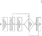
- controller 502 receives an input from a user for setting a desired temperature (e.g. temperature of the vehicle seat).
- a desired temperature e.g. temperature of the vehicle seat
- the input device is not shown in Fig. 5 , but could include a dial, button, touchscreen, etc.
- controller 502 applies a predetermined voltage to the busbars of fabric layer element 202 which then produces heat.
- controller 502 uses temperature sensor 506 to monitor temperature of the fabric layer element 202. Temperature sensor 506 may be in direct contact, or in close proximity to fabric layer element 202.
- controller 502 determines if the desired temperature has been reached. If the desired temperature has been reached, then in step 610, the controller 502 stops applying voltage to the busbars. If, however, the desired temperature is not reached, controller 502 continues to apply the voltage to the busbars.
- a dense network of short fibers causes the non-woven web to be relatively insensitive to holes or localised damage.
- the outer insulating and reinforcing layers and connecting adhesive layers of the heater element allow the use of the optimum fiber length in the non-woven web to provide uniformity of electrical resistance throughout the conducting non-woven layer.
- Weight of the outer layers typically varies between 20-100 grams/m2.
- outer layers can be compatible with the materials into which they are embedded, by having coated or impregnated reinforcing layers that match or otherwise favourably pair chemically to the material in which they are embedded.
- outer layers comprising a woven glass coated Polyvinyl chloride (PVC) may be used in a heating element to be embedded in a PVC floor covering for a heated floor application, and woven nylon/acrylic fabric outer layers may be used for producing heated clothing.
- PVC Polyvinyl chloride
- the heater element In applications where the heater element is embedded in viscous materials, like rubber or concrete, it may be desirable to perforate the heater element material such that an additional mechanical bond is achieved. Since the non-woven web is insensitive to holes, the ability to include such perforations to provide mechanical bonding is an added advantage over other state of the art heaters.
- the electrical resistance of the perforated heater increases typically by 35-50% due to the reduced area. In some applications, an open area of 18-20% may give optimum heater performance.
- An exemplary hole pattern may comprise, for example, 1.5mm diameter holes spaced 3.5mm on center.
- the adhesive layers connecting the outer plies to the inner conducting layer are typically applied at 15-20 g/m2, and may comprise any compatible thermoplastic or thermoset web adhesive, such as PET, Thermoplastic polyurethane (TPU), Ethylene-vinyl acetate (EVA), polyamide, polyolefin, epoxy, polyimide, etc.
- the heater hybrid construction material may be manufactured on a commercial basis on state of the art low pressure/temp continuous belt presses. Typical machine production speeds of 10 mts/min are achievable.
- the copper busbar strips and bonded to the non-woven inner conductive layer such that full electrical continuity is achieved throughout the heater material.
- the copper busbar strips may be bonded to the inner conductive layer at the same time as the entire heating fabric is consolidated, or prior to consolidation with the other layers.
- the inner conductive layer and copper busbar strips (with sufficient adhesive between them) alone, or together with the other layers as described herein, may be fed into a laminating machine, such as a laminating belt press.
- step 702 the manufacturer forms (e.g. via Wet-Laid Manufacturing) the fiber layer (e.g. Carbon Fiber either Perforated or Non-Perforated).
- step 704 the manufacturer bonds metallic strips (e.g. Coated copper) to predetermined positions (e.g. specific distances from each other) on the formed fiber layer.
- step 706 the manufacturer connects electrical wires to each of the metallic strips which allow application of the supply voltage.
- step 708 the manufacturer applies adhesive layers to both sides of the fiber layer.
- step 710 the manufacturer applies insulating layers to both adhesive layers.
- this manufacturing process produces the fabric heating element 100 shown in Fig. 1 .
Landscapes
- Engineering & Computer Science (AREA)
- Textile Engineering (AREA)
- Surface Heating Bodies (AREA)
- Resistance Heating (AREA)
Claims (15)
- Un élément chauffant de chauffage de tissu (100, 200, 202, 300) comprenant : une couche de fibres non-tissée électriquement conductrice (article 4) comprenant une pluralité de fibres ; et au moins deux bandes conductrices (article 3, 308,314) raccordées électriquement à la couche de fibres sur une longueur prédéterminée, positionnée à côté des extrémités opposés de la couche de fibres, et configuré pour être raccordé électriquement à une source d'alimentation (504), caractérisée en ce que: la couche de fibres non-tissées comprend une couche par voie humide de fibres individuelles non enchevêtrées en l'absence de particules conductrices, ces fibres comportant des fibres conductrices, des fibres non conductrices, ou une combination de celles-ci, qui ont une longueur moyenne inférieure à 12 mm, dans laquelle l'une des fibres non-conductrices est une fibre de verre.
- L'élément de chauffage de tissu (100, 200, 202, 300) de la revendication 1, dans lequel la pluralité de fibres conductrices comprend des fibres de carbone. L'élément de chauffage de tissu (100, 200, 202, 300) de la revendication 1 ou 2, dans lequel la couche de fibres a une résistance électrique uniforme dans n'importe quelle direction.
- L'élément de chauffage de tissu (100, 200, 202, 300) de la revendication 1 ou 2, dans lequel la couche de fibres a une résistance électrique uniforme dans n'importe quelle direction.
- L'élément de chauffage de tissu (100, 200, 202, 300) de l'une quelconque des revendications 1 à 3, dans lequel un ou plusieurs de la pluralité de fibres conductrices est une fibre non-métallique comportant un revêtement métallique.
- L'élément de chauffage de tissu (100, 202, 300) de l'une quelconque des revendications 1 à 4, dans lequel la couche de fibres comporte une pluralité de perforations qui augmentent la résistance électrique sur la portion perforée de la couche de fibres par rapport à la résistance en l'absence de perforations.
- L'élément de chauffage de tissu (100, 202, 300) de la revendication 5, dans lequel les perforations définissent une zone ouverte dans la couche de fibres dans une plage de 18 à 20 %.
- L'élément de chauffage de tissu de l'une quelconque des revendications 1 à 6, comprenant par ailleurs : au moins une bande conductrice supplémentaire (310, 312) raccordée sur une autre longueur prédéterminée de la couche de fibres entre les au moins deux bandes conductrices (308, 314).
- L'élément de chauffage de tissu de la revendication 7, dans lequel l'une des au moins deux bandes conductrices (308) et au moins une bande conductrice supplémentaire (310) sont espacées sur la couche de fibres sur une première largeur, et dans lequel une autre des au moins deux bandes conductrices (314) et des au moins une bande conductrice supplémentaire (312) sont espacées sur la couche de fibres sur une seconde largeur différente de la première largeur.
- Un élément de chauffage de tissu (508), comprenant : l'élément de chauffage de tissu de l'une quelconque des revendications 1 à 8 ; une première couche adhésive (article 2) adhérant à un premier côté de la couche de fibres et une première couche isolante (article 1) ; et une seconde couche adhésive (article 5) adhérant à un second côté de la couche de fibres et une seconde couche isolante (article 6).
- Le dispositif de chauffage de tissu (508) de la revendication 9, dans lequel chacun des au moins deux bandes conductrices comporte un raccordement électrique à l'alimentation électrique (504).
- Un système de chauffage de tissu (500), comprenant : le système de chauffage de tissu (508) de la revendications 9 ou 10; et un contrôleur (502) raccordé électriquement à l'alimentation électrique (504) et les au moins deux bandes conductrices, le contrôleur configure pour appliquer une tension fournie par l'alimentation électrique des au moins deux bandes conductrices.
- Le système de chauffage de tissu (500) de la revendication 11, comprenant par ailleurs : un dispositif de saisie de température conçu pour régler un niveau de chaleur souhaité à produire par le dispositif de chauffage de tissu ; et un capteur de température (506) conçu pour détecter la chaleur produite par la couche de fibres en réaction à une indication du dispositif de saisie de température, et pour transmettre un signal au contrôleur (504) pour indiquer le niveau de chaleur détecté.
- Le système de chauffage de tissu (500) de la revendications 11 ou 12 : dans lequel l'élément de tissu comprises au moins four bandes conductrices (308, 310, 312, 314), et chaque bande conductrice est raccordé électriquement à l'alimentation électrique (504), et dans lequel le contrôleur est configuré par ailleurs pour appliquer une première tension sur une première portion (302) de la couche de fibres entre une première bande conductrice (308) et une seconde bande conductrice (310), et appliquer une seconde tension sur une seconde portion de la couche de fibres (304) entre une troisième bande conductrice (312) et une quatrième bande conductrice (314).
- Le système de chauffage de tissu de l'une quelconque des revendications 11 à 13, dans lequel le contrôleur (504) est configuré pour faire varier la tension appliquée sur les bandes conductrices afin de produire une quantité prédéterminée de chaleur via la couche de fibre.
- Le système de chauffage de tissu de l'une quelconque des revendications 11 à 14, dans lequel le système de chauffage de tissu est un composant d'au moins l'un des éléments suivants : capitonnage d'un véhicule, vêtement, et un revêtement de sol.
Priority Applications (2)
| Application Number | Priority Date | Filing Date | Title |
|---|---|---|---|
| EP20161190.2A EP3691408A1 (fr) | 2015-01-12 | 2016-01-12 | Élément de chauffage de tissus |
| PL16709103T PL3245844T3 (pl) | 2015-01-12 | 2016-01-12 | Tkaninowy element grzewczy |
Applications Claiming Priority (2)
| Application Number | Priority Date | Filing Date | Title |
|---|---|---|---|
| US201562102169P | 2015-01-12 | 2015-01-12 | |
| PCT/IB2016/000095 WO2016113633A1 (fr) | 2015-01-12 | 2016-01-12 | Élément chauffant en tissu |
Related Child Applications (2)
| Application Number | Title | Priority Date | Filing Date |
|---|---|---|---|
| EP20161190.2A Division EP3691408A1 (fr) | 2015-01-12 | 2016-01-12 | Élément de chauffage de tissus |
| EP20161190.2A Division-Into EP3691408A1 (fr) | 2015-01-12 | 2016-01-12 | Élément de chauffage de tissus |
Publications (2)
| Publication Number | Publication Date |
|---|---|
| EP3245844A1 EP3245844A1 (fr) | 2017-11-22 |
| EP3245844B1 true EP3245844B1 (fr) | 2020-05-27 |
Family
ID=55521751
Family Applications (2)
| Application Number | Title | Priority Date | Filing Date |
|---|---|---|---|
| EP20161190.2A Withdrawn EP3691408A1 (fr) | 2015-01-12 | 2016-01-12 | Élément de chauffage de tissus |
| EP16709103.2A Active EP3245844B1 (fr) | 2015-01-12 | 2016-01-12 | Élément chauffant en tissu |
Family Applications Before (1)
| Application Number | Title | Priority Date | Filing Date |
|---|---|---|---|
| EP20161190.2A Withdrawn EP3691408A1 (fr) | 2015-01-12 | 2016-01-12 | Élément de chauffage de tissus |
Country Status (7)
| Country | Link |
|---|---|
| US (1) | US10925119B2 (fr) |
| EP (2) | EP3691408A1 (fr) |
| CN (1) | CN107409442B (fr) |
| CA (1) | CA2973557C (fr) |
| ES (1) | ES2813579T3 (fr) |
| PL (1) | PL3245844T3 (fr) |
| WO (1) | WO2016113633A1 (fr) |
Families Citing this family (27)
| Publication number | Priority date | Publication date | Assignee | Title |
|---|---|---|---|---|
| KR102051617B1 (ko) | 2014-02-14 | 2019-12-03 | 젠썸 인코포레이티드 | 전도식 대류식 기온 제어 시트 |
| US11857004B2 (en) | 2014-11-14 | 2024-01-02 | Gentherm Incorporated | Heating and cooling technologies |
| EP3218942B1 (fr) | 2014-11-14 | 2020-02-26 | Charles J. Cauchy | Technologies de chauffage et de refroidissement |
| US11639816B2 (en) | 2014-11-14 | 2023-05-02 | Gentherm Incorporated | Heating and cooling technologies including temperature regulating pad wrap and technologies with liquid system |
| CA3001643A1 (fr) * | 2015-10-19 | 2017-04-27 | Laminaheat Holding Ltd. | Elements de chauffage stratifies ayant une resistance personnalisee ou non uniforme et/ou des formes irregulieres et procedes de fabrication |
| WO2019086549A1 (fr) * | 2017-10-31 | 2019-05-09 | Laminaheat Holding Ltd. | Ensembles de barres-bus à profil mince et systèmes de chauffage reliés électriquement à ceux-ci |
| DE102017001097A1 (de) * | 2017-02-07 | 2018-08-09 | Gentherm Gmbh | Elektrisch leitfähige Folie |
| US10805988B2 (en) * | 2017-03-14 | 2020-10-13 | Encompass Group, Llc | Metalized fabric heating blanket and method of manufacturing such |
| CN206908878U (zh) * | 2017-03-16 | 2018-01-19 | 苏州汉纳材料科技有限公司 | 超薄碳纳米管加热元件及超薄碳纳米管踢脚线加热器 |
| US10993557B2 (en) | 2018-08-03 | 2021-05-04 | American Sterilizer Company | Pressure management warming headrest |
| US20190143858A1 (en) * | 2017-11-14 | 2019-05-16 | The Endeavour Group, Inc. | Seat Heater |
| US11166344B2 (en) * | 2018-01-25 | 2021-11-02 | University Of Massachusetts | Electrically-heated fiber, fabric, or textile for heated apparel |
| CN108271280B (zh) * | 2018-01-26 | 2024-04-09 | 佛山市丰晴科技有限公司 | 一种石墨烯变流电热膜 |
| CN110225606A (zh) * | 2018-03-02 | 2019-09-10 | 智能纺织科技股份有限公司 | 可加热织物 |
| EP3544372A1 (fr) | 2018-03-22 | 2019-09-25 | LaminaHeat Holding Ltd. | Éléments de chauffage laminaires à résistance personnalisée ou non uniforme et/ou formes irrégulières et leurs procédés de fabrication |
| US20200035898A1 (en) | 2018-07-30 | 2020-01-30 | Gentherm Incorporated | Thermoelectric device having circuitry that facilitates manufacture |
| WO2020161303A1 (fr) | 2019-02-08 | 2020-08-13 | Laminaheat Holding Ltd. | Élément chauffant laminaire perforé |
| US11152557B2 (en) | 2019-02-20 | 2021-10-19 | Gentherm Incorporated | Thermoelectric module with integrated printed circuit board |
| US20220124877A1 (en) * | 2019-02-20 | 2022-04-21 | Tomoegawa Co., Ltd. | Sheet-like heater |
| WO2021025663A1 (fr) * | 2019-08-02 | 2021-02-11 | Gentherm Incorporated | Couche thermoconductrice |
| USD911038S1 (en) | 2019-10-11 | 2021-02-23 | Laminaheat Holding Ltd. | Heating element sheet having perforations |
| WO2021259896A1 (fr) | 2020-06-22 | 2021-12-30 | Laminaheat Holding Ltd. | Appareil de chauffage par rayonnement à panneau de construction semblable à une plaque de plâtre |
| US20220185069A1 (en) * | 2020-12-11 | 2022-06-16 | Lear Corporation | Vehicle zone heating system |
| KR102554876B1 (ko) * | 2021-04-13 | 2023-07-12 | 현대자동차주식회사 | 에너지 효율이 향상된 자동차용 시트히터 |
| EP4102933B1 (fr) | 2021-06-07 | 2023-12-13 | Calefact Limited | Dispositif de chauffage flexible et ses procédés de fabrication et d'utilisation |
| EP4364528A1 (fr) | 2021-06-28 | 2024-05-08 | LaminaHeat Holding Ltd. | Appareil de chauffage par rayonnement à panneau de construction semblable à une plaque de plâtre |
| DE102021120697A1 (de) | 2021-08-09 | 2023-02-09 | Giesecke+Devrient Currency Technology Gmbh | Verfahren zur kontaktierung eines elektrisch leitenden papiergefüges, verbundkörper und verwendung |
Family Cites Families (156)
| Publication number | Priority date | Publication date | Assignee | Title |
|---|---|---|---|---|
| US2557983A (en) | 1949-03-22 | 1951-06-26 | Pittsburgh Plate Glass Co | Transparent electroconductive article |
| DE1615494A1 (de) * | 1967-07-27 | 1971-02-25 | Hermann Vierling | Durch elektrische Widerstandsheizung erwaermbarer Heizbelag |
| JPS513097B1 (fr) | 1970-09-21 | 1976-01-31 | ||
| US4007083A (en) | 1973-12-26 | 1977-02-08 | International Paper Company | Method for forming wet-laid non-woven webs |
| US4200488A (en) | 1975-02-20 | 1980-04-29 | International Paper Company | Viscous dispersion for forming wet-laid, non-woven fabrics |
| US4049491A (en) | 1975-02-20 | 1977-09-20 | International Paper Company | Viscous dispersion for forming wet-laid, non-woven fabrics |
| US4534886A (en) * | 1981-01-15 | 1985-08-13 | International Paper Company | Non-woven heating element |
| DE3225754A1 (de) | 1982-07-09 | 1984-01-12 | Hülsbeck & Fürst GmbH & Co KG, 5620 Velbert | Verfahren zur schliesswirksamen wechselwirkung eines schluesselartigen teils mit einem schlossartigen teil |
| US4719335A (en) | 1984-01-23 | 1988-01-12 | Raychem Corporation | Devices comprising conductive polymer compositions |
| US4728395A (en) | 1984-10-12 | 1988-03-01 | Stackpole Fibers Company, Inc. | Controlled resistivity carbon fiber paper and fabric sheet products and method of manufacture |
| FR2578377B1 (fr) | 1984-12-26 | 1988-07-01 | Aerospatiale | Element chauffant de dispositif de degivrage d'une structure alaire, dispositif et son procede d'obtention |
| US4725717A (en) | 1985-10-28 | 1988-02-16 | Collins & Aikman Corporation | Impact-resistant electrical heating pad with antistatic upper and lower surfaces |
| US4931627A (en) | 1988-08-16 | 1990-06-05 | Illinois Tool Works Inc. | Positive temperature coefficient heater with distributed heating capability |
| US4960979A (en) * | 1988-12-06 | 1990-10-02 | Makoto Nishimura | Electrically heatable sheet prepared by paper |
| GB9020400D0 (en) | 1990-09-19 | 1990-10-31 | Raychem Sa Nv | Electrical heating tape |
| DE4321474C2 (de) * | 1993-06-28 | 1996-05-23 | Ruthenberg Gmbh Waermetechnik | Flächenheizelement |
| KR950013314A (ko) | 1993-10-13 | 1995-05-17 | 유끼꼬 하야시 | 면상 감열소자 및 그것을 가진 면상 히이터 |
| WO1995015670A1 (fr) | 1993-11-30 | 1995-06-08 | Alliedsignal Inc. | Dispositif de chauffage composite electriquement conducteur et procede de fabrication de ce dispositif |
| CA2176359C (fr) | 1993-11-30 | 2004-01-27 | David Charles Lawson | Dispositif de chauffage composite electriquement conducteur et procede de fabrication de ce dispositif |
| DE4447407C2 (de) | 1994-12-24 | 2001-12-13 | Debolon Dessauer Bodenbelaege | Flexibles Flächenheizelement und Verfahren zur Herstellung eines flexiblen Flächenheizelementes |
| JP3090029B2 (ja) | 1996-03-25 | 2000-09-18 | 富士電機株式会社 | 定着ローラおよびその製造方法 |
| EP0894417B1 (fr) | 1996-04-19 | 2000-12-27 | Thermion Systems International | Procede de rechauffage de la surface d'une antenne parabolique |
| US5981911A (en) | 1996-04-19 | 1999-11-09 | Thermicon Systems International | Method for heating the surface of a food receptacle |
| US5954977A (en) | 1996-04-19 | 1999-09-21 | Thermion Systems International | Method for preventing biofouling in aquatic environments |
| US5932124A (en) | 1996-04-19 | 1999-08-03 | Thermion Systems International | Method for heating a solid surface such as a floor, wall, or countertop surface |
| JP3181506B2 (ja) | 1996-05-24 | 2001-07-03 | 株式会社ダイリン商事 | 遠赤外線輻射体および遠赤外線輻射方法 |
| US6037572A (en) | 1997-02-26 | 2000-03-14 | White Consolidated Industries, Inc. | Thin film heating assemblies |
| WO1998053200A1 (fr) | 1997-05-20 | 1998-11-26 | Thermion Systems International | Dispositif et procede de chauffage et degivrage d'aubes d'eolienne |
| FR2773043B1 (fr) | 1997-12-24 | 2000-03-10 | Messier Bugatti | Panneau radiant a element chauffant en fibres de carbone et son procede de fabrication |
| AU2183499A (en) | 1998-01-28 | 1999-08-16 | Toto Ltd. | Heat radiator |
| US6108581A (en) | 1998-05-30 | 2000-08-22 | Jung; Yeon-Kweon | Far infrared ray diffusing mat |
| DE19831023A1 (de) | 1998-07-10 | 2000-01-13 | Kreco Kreiner Consulting Ges F | Elektrische Versorgungseinrichtung für eine Widerstandsheizschicht einer Heizdecke und heizbares Rettungssystem |
| US6184496B1 (en) | 1998-08-06 | 2001-02-06 | Clearpath, Inc. | Driveway, walkway and roof snow and ice melting mat |
| WO2001021044A1 (fr) | 1999-09-22 | 2001-03-29 | Matsushita Electric Industrial Co. Ltd. | Element chauffant plan |
| WO2001043507A1 (fr) | 1999-12-10 | 2001-06-14 | Thermion Systems International | Dispositif de chauffage de stratifie thermoplastique et procede de fabrication associe |
| SE518872C2 (sv) | 2000-01-28 | 2002-12-03 | Polyohm Ab | Anordning för golvuppvärmning |
| KR100337609B1 (ko) | 2000-08-26 | 2002-05-22 | 서영석 | 세라믹 탄소섬유지 면상발열체 |
| JP3077410U (ja) | 2000-10-31 | 2001-05-18 | 林 京子 | 炭素繊維混抄シート発熱体 |
| US20050205551A1 (en) | 2001-02-15 | 2005-09-22 | Integral Technologies, Inc. | Low cost heated clothing manufactured from conductive loaded resin-based materials |
| US7372006B2 (en) | 2001-02-15 | 2008-05-13 | Integral Technologies, Inc | Low cost heating devices manufactured from conductive loaded resin-based materials |
| CN2502480Y (zh) | 2001-09-27 | 2002-07-24 | 伍百炜 | 炭素纤维电热器件 |
| US6741805B2 (en) | 2001-09-27 | 2004-05-25 | Bai Wei Wu | Flexible graphite felt heating elements and a process for radiating infrared |
| DE10151298A1 (de) | 2001-10-17 | 2003-04-30 | Joerg Runge-Rannow | Heizfolie aus mehreren Schichten und Verfahren zu deren Herstellung |
| US7638735B2 (en) | 2002-02-11 | 2009-12-29 | The Trustees Of Dartmouth College | Pulse electrothermal and heat-storage ice detachment apparatus and methods |
| US20080223842A1 (en) | 2002-02-11 | 2008-09-18 | The Trustees Of Dartmouth College | Systems And Methods For Windshield Deicing |
| WO2008060696A2 (fr) | 2006-05-22 | 2008-05-22 | The Trustees Of Dartmouth College | Dégivrage électrothermique par impulsions de formes complexes |
| AU2003213017A1 (en) | 2002-02-11 | 2003-09-04 | The Trustees Of Dartmouth College | Systems and methods for modifying an ice-to-object interface |
| US20080196429A1 (en) | 2002-02-11 | 2008-08-21 | The Trustees Of Dartmouth College | Pulse Electrothermal And Heat-Storage Ice Detachment Apparatus And Method |
| US20090235681A1 (en) | 2002-02-11 | 2009-09-24 | The Trustees Of Dartmouth College | Pulse Electrothermal Mold Release Icemaker For Refrigerator Having Interlock Closure And Baffle For Safety |
| US8921739B2 (en) | 2002-02-11 | 2014-12-30 | The Trustees Of Dartmouth College | Systems and methods for windshield deicing |
| US8405002B2 (en) | 2002-02-11 | 2013-03-26 | The Trustees Of Dartmouth College | Pulse electrothermal mold release icemaker with safety baffles for refrigerator |
| US7570760B1 (en) | 2004-09-13 | 2009-08-04 | Sun Microsystems, Inc. | Apparatus and method for implementing a block cipher algorithm |
| AU2003247738A1 (en) | 2002-06-28 | 2004-01-19 | Thermion Systems International | Method for accelerated bondline curing |
| US6727471B2 (en) | 2002-07-05 | 2004-04-27 | Clarke B. Evans | Modular flexible heater system with integrated connectors |
| US20040035853A1 (en) | 2002-08-26 | 2004-02-26 | Aaron Pais | Heating mat |
| DE10243611A1 (de) | 2002-09-19 | 2004-04-01 | Siemens Ag | Patientenlagerungsvorrichtung |
| CA2464923A1 (fr) | 2003-04-10 | 2004-10-10 | Integral Technologies, Inc. | Dispositifs de chauffage peu couteux fabriques avec des materiaux a base de resine a charge conductrice |
| KR100547189B1 (ko) | 2003-04-23 | 2006-01-31 | 스타전자(주) | 그라파이트 펠트를 이용하는 탄소 발열 장치의 제조 방법 |
| DE20314061U1 (de) | 2003-09-10 | 2003-11-20 | Haug Rainer | Heizplatte zum elektrischen Heizen von Gebäuderäumen |
| TWI257822B (en) | 2003-09-19 | 2006-07-01 | Tex Ray Ind Co Ltd | Flexible electro-heating apparatus and fabrication thereof |
| CA2547508A1 (fr) | 2003-10-29 | 2005-05-12 | Thermion Systems International | Procede de liaison de matieres thermoplastiques |
| US20050167412A1 (en) | 2004-01-30 | 2005-08-04 | Anson Rebecca L. | Electrical garment heating system |
| US7247822B2 (en) | 2004-02-05 | 2007-07-24 | Methode Electronics, Inc. | Carbon fiber heating element assembly and methods for making |
| KR100535175B1 (ko) | 2004-03-29 | 2005-12-09 | 주식회사 센테크 | 카본유연성 발열구조체 제조용 전도성 조성물과 이를 이용한 카본유연성 발열구조체 및 이의 제조방법 |
| DE102004026458A1 (de) | 2004-05-29 | 2006-01-05 | I.G. Bauerhin Gmbh, Elektrotechnische Werke | Überwachungseinrichtung für flexible Heizelemente |
| JP2008503710A (ja) | 2004-06-22 | 2008-02-07 | ザ トラスティーズ オブ ダートマウス カレッジ | 氷を剥がすためのパルスシステムおよび方法 |
| US7105782B2 (en) | 2004-11-15 | 2006-09-12 | Steven Yue | Electrothermal article |
| US7820945B2 (en) | 2004-11-22 | 2010-10-26 | Pacific Medical Co., Ltd. | Heating fabric and manufacturing method thereof |
| DE102005003371A1 (de) | 2005-01-24 | 2006-08-03 | Kiersch Composite Gmbh | Anordnung zum Erzeugen eines elektrischen Stromflusses durch Kohlenstofffasern |
| US9945080B2 (en) | 2005-02-17 | 2018-04-17 | Greenheat Ip Holdings, Llc | Grounded modular heated cover |
| US20080272106A1 (en) | 2007-05-03 | 2008-11-06 | David Naylor | Grounded modular heated cover |
| US20090101632A1 (en) | 2005-02-17 | 2009-04-23 | David Naylor | Heating unit for direct current applications |
| US20060289468A1 (en) | 2005-03-17 | 2006-12-28 | Randy Seibert | Snow and ice melting mat |
| CN1841713A (zh) | 2005-03-31 | 2006-10-04 | 清华大学 | 热界面材料及其制作方法 |
| DE102005015051A1 (de) | 2005-03-31 | 2006-10-19 | Ewald Dörken Ag | Flächenheizeinrichtung |
| DE102005015050A1 (de) | 2005-03-31 | 2006-10-12 | Ewald Dörken Ag | Flächenheizeinrichtung |
| US20060278631A1 (en) | 2005-06-10 | 2006-12-14 | Challenge Carbon Technology Co., Ltd. Of Taiwan | Laminate fabric heater and method of making |
| DE102005026766A1 (de) | 2005-06-10 | 2006-12-14 | Engelmann Automotive Gmbh | Verfahren zur Herstellung eines beheizbaren Formkörpers, insbesondere für Außenrückblickspiegel mit einem Heizelelement |
| FR2888081B1 (fr) | 2005-06-30 | 2007-10-05 | Aerazur Soc Par Actions Simpli | Stratifie contenant en son sein un tissu conducteur de l'electricite, degivreur electrothermique comportant ce stratifie et partie d'un aerodyne comportant ce degivreur. |
| US20070056946A1 (en) | 2005-09-14 | 2007-03-15 | Chien-Chou Chen | Warming device for a car seat cover |
| DE102005051738A1 (de) | 2005-10-28 | 2007-05-03 | Daimlerchrysler Ag | Flächenheizelement für einen Kraftfahrzeugsitz |
| EP1796432A1 (fr) | 2005-12-09 | 2007-06-13 | Roth Werke GmbH | Feuille chauffante |
| US7923668B2 (en) * | 2006-02-24 | 2011-04-12 | Rohr, Inc. | Acoustic nacelle inlet lip having composite construction and an integral electric ice protection heater disposed therein |
| DE102006021649C5 (de) | 2006-05-08 | 2013-10-02 | W.E.T. Automotive Systems Ag | Flächiges Heizelement |
| JP4897360B2 (ja) | 2006-06-08 | 2012-03-14 | ポリマテック株式会社 | 熱伝導性成形体及びその製造方法 |
| KR100973593B1 (ko) | 2006-06-27 | 2010-08-03 | 앤에이오에스 주식회사 | 카본극세사를 이용한 면상발열체 제조방법 및 이를 통해 제조된 카본극세사를 이용한 면상발열체 |
| US7268325B1 (en) | 2006-10-23 | 2007-09-11 | Linkwin Technology Co., Ltd. | Method of making flexible sheet heater |
| DE102006058198C5 (de) | 2006-12-07 | 2018-01-18 | Fibretemp Gmbh & Co. Kg | Elektrisch beheizbares Formwerkzeug in Kunststoffbauweise |
| US20110068098A1 (en) | 2006-12-22 | 2011-03-24 | Taiwan Textile Research Institute | Electric Heating Yarns, Methods for Manufacturing the Same and Application Thereof |
| US7884307B2 (en) | 2006-12-22 | 2011-02-08 | Taiwan Textile Research Institute | Electric heating textile |
| US20080156786A1 (en) | 2006-12-29 | 2008-07-03 | Seung Mo Choi | Direct current powered heating pad for bed |
| US20080166563A1 (en) | 2007-01-04 | 2008-07-10 | Goodrich Corporation | Electrothermal heater made from thermally conducting electrically insulating polymer material |
| JP5278316B2 (ja) | 2007-01-22 | 2013-09-04 | パナソニック株式会社 | 面状発熱体 |
| CN101012700A (zh) | 2007-02-01 | 2007-08-08 | 傅晓乐 | 一种红外线电热架空发热地板块及其组合地板 |
| DE102007010145A1 (de) | 2007-02-28 | 2008-09-11 | W.E.T Automotive Systems Aktiengesellschaft | Elektrischer Leiter |
| ATE461601T1 (de) | 2007-08-03 | 2010-04-15 | Frenzelit Werke Gmbh & Co Kg | Flächenheizsystem |
| DE112008002682A5 (de) | 2007-10-18 | 2010-07-01 | W.E.T. Automotive Systems Ag | Elektrische Leiteinrichtung |
| US20090127250A1 (en) | 2007-11-21 | 2009-05-21 | Pang-Hua Chang | Portable Body Joint Electric Heating Pad Fabric |
| TW200925344A (en) | 2007-12-12 | 2009-06-16 | Everest Textile Co Ltd | Electric heating fabric device |
| US20110036829A1 (en) | 2007-12-26 | 2011-02-17 | Hodogaya Chemical Co., Ltd. | Planar heating element obtained using dispersion of fine carbon fibers in water and process for producing the planar heating element |
| US20100279177A1 (en) | 2008-01-03 | 2010-11-04 | Hsiharng Yang | Carbon fiber conductive sheet and manufacturing method thereof |
| WO2009104361A1 (fr) | 2008-02-18 | 2009-08-27 | パナソニック株式会社 | Élément chauffant polymère |
| DE202008005084U1 (de) | 2008-04-11 | 2009-08-13 | Christoph von Zeschau Gesellschaft mit beschränkter Haftung | Elektrischer Flächenheizkörper |
| EP2329682A2 (fr) | 2008-05-05 | 2011-06-08 | Elena Tolmacheva | Ruban polymère électroconducteur et tissu polymère à base de fibres polymères, de fils, de fils retors et de cordons électroconducteurs pour éléments chauffants, tissus chauffants plats et analogues, et procédé de production d'éléments chauffants plats |
| US20090289046A1 (en) | 2008-05-23 | 2009-11-26 | Simon Nicholas Richmond | Heated Garment |
| WO2009144678A2 (fr) | 2008-05-29 | 2009-12-03 | Kimberly-Clark Worldwide, Inc. | Tissus conducteurs contenant des pistes électriques et procédé pour réaliser ces tissus |
| US8866052B2 (en) * | 2008-05-29 | 2014-10-21 | Kimberly-Clark Worldwide, Inc. | Heating articles using conductive webs |
| DE102008039840A1 (de) | 2008-08-27 | 2010-03-04 | Sgl Carbon Ag | Streckgerissene Carbonfasergarne für eine Heizvorrichtung |
| US7827675B2 (en) | 2008-09-11 | 2010-11-09 | Ching-Ling Pan | Method of manufacturing an activated carbon fiber soft electric heating product |
| EP2200396A1 (fr) | 2008-12-19 | 2010-06-23 | Sika Technology AG | Chauffage de surface électrique |
| US20100176118A1 (en) * | 2009-01-14 | 2010-07-15 | David Lee | Electric heating film and method of producing the same |
| US20100200558A1 (en) | 2009-02-12 | 2010-08-12 | Liu Ying-Hsiung | Electrical heating blanket |
| WO2010116809A1 (fr) | 2009-04-07 | 2010-10-14 | Anbe Yoshinobu | Appareil de chauffage pour inspection par rayons x |
| US20100282458A1 (en) | 2009-05-08 | 2010-11-11 | Yale Ann | Carbon fiber heating source and heating system using the same |
| LT2430878T (lt) | 2009-05-11 | 2022-11-10 | Wilhelm Zimmerer | Elektrinis paviršiaus šildymo įrenginys, jo gamybos būdas ir medžiaga |
| CN101998706B (zh) | 2009-08-14 | 2015-07-01 | 清华大学 | 碳纳米管织物及应用该碳纳米管织物的发热体 |
| US20110046703A1 (en) | 2009-08-18 | 2011-02-24 | Chien-Chou Chen | Heating device for low voltage thermal therapy |
| US20110041246A1 (en) | 2009-08-20 | 2011-02-24 | Hong Kong Applied Science And Technology Research Institute Co., Ltd. | Systems and methods providing temperature regulated cushion structure |
| US20110084054A1 (en) | 2009-10-13 | 2011-04-14 | Susan Bahr | Massage stone warming apparatus |
| WO2011050787A2 (fr) | 2009-10-26 | 2011-05-05 | Fachhochschule Dortmund | Dispositif pour la mise en contact électrique de stratifiés électroconducteurs en plastiques renforcés de fibres de carbone (stratifiés en prfc) |
| JP5675138B2 (ja) | 2010-03-25 | 2015-02-25 | 東京エレクトロン株式会社 | プラズマ処理装置 |
| FR2958994B1 (fr) | 2010-04-14 | 2013-01-11 | Total Sa | Couverture chauffante pour dispositif de transport d'un fluide comprenant un hydrocarbure. |
| FR2958992B1 (fr) | 2010-04-14 | 2012-05-04 | Total Sa | Conduite pour le transport d'un fluide comprenant un hydrocarbure, et procede de fabrication d'une telle conduite. |
| FR2958991B1 (fr) | 2010-04-14 | 2012-05-04 | Total Sa | Conduite pour le transport d'un fluide comprenant un hydrocarbure, et procede de fabrication d'une telle conduite. |
| US9968214B2 (en) | 2010-04-16 | 2018-05-15 | Carbon Fibers Heatingtechnologies | Carbon fiber heating element |
| US8544942B2 (en) | 2010-05-27 | 2013-10-01 | W.E.T. Automotive Systems, Ltd. | Heater for an automotive vehicle and method of forming same |
| US10063642B2 (en) | 2010-08-21 | 2018-08-28 | Qualcomm Incorporated | Method and apparatus for supporting location services via a generic location session |
| US8308889B2 (en) | 2010-08-27 | 2012-11-13 | Alliant Techsystems Inc. | Out-of-autoclave and alternative oven curing using a self heating tool |
| CA2724165A1 (fr) | 2010-12-02 | 2012-06-02 | Alternative Heating Systems Inc. | Systeme de mise a la terre |
| PL2656685T3 (pl) | 2010-12-21 | 2016-04-29 | Milwaukee Composites Inc | Panel z ogrzewaną warstwą |
| US20120168430A1 (en) | 2010-12-30 | 2012-07-05 | Warm Waves, Llc | Grounded Film Type Heater |
| EP2689194A2 (fr) | 2011-03-24 | 2014-01-29 | Ulrich, Peter G. | Dispositif chauffant |
| CN202299313U (zh) | 2011-11-04 | 2012-07-04 | 孫侑成 | 新型地热地板 |
| US20140001170A1 (en) | 2011-04-11 | 2014-01-02 | Skala Stone, Inc. | Heatable marble composite slab and method for connecting the same |
| JP5436491B2 (ja) | 2011-05-20 | 2014-03-05 | 北陸エステアール協同組合 | 面状発熱体 |
| DE102011119844A1 (de) | 2011-05-26 | 2012-12-13 | Eads Deutschland Gmbh | Verbundstruktur mit Eisschutzvorrichtung sowie Herstellverfahren |
| US20130001212A1 (en) | 2011-06-29 | 2013-01-03 | Mangoubi Daniel R | Electrical heating jacket |
| JP2013041805A (ja) | 2011-07-20 | 2013-02-28 | Fuji Impulse Kk | インパルス式ヒートシーラー用のヒーター |
| GB2493001B (en) | 2011-07-21 | 2016-05-11 | Laminaheat Holding Ltd | Laminate items |
| DE102011109578B4 (de) | 2011-08-05 | 2015-05-28 | Heraeus Noblelight Gmbh | Verfahren zur Herstellung eines elektrisch leitenden Materials, elektrisch leitendes Material sowie Strahler mit elektrisch leitendem Material |
| US10201039B2 (en) * | 2012-01-20 | 2019-02-05 | Gentherm Gmbh | Felt heater and method of making |
| US20130228562A1 (en) | 2012-03-02 | 2013-09-05 | Chien-Chou Chen | Heater sewn on clothes |
| US20130319997A1 (en) | 2012-05-31 | 2013-12-05 | Ming-Yi Chao | Keep-warming device with time control function |
| US11425796B2 (en) | 2013-04-17 | 2022-08-23 | Augustine Temperature Management, Llc | Conformable heating blanket |
| DE202013006416U1 (de) | 2013-07-17 | 2014-10-22 | Blanke Gmbh & Co. Kg | Kombiniertes Entkopplungs- und Heizungssystem |
| DE102013214548B4 (de) | 2013-07-25 | 2022-08-11 | Bayerische Motoren Werke Aktiengesellschaft | Fahrzeug mit einer elektrischen Heizeinrichtung |
| KR20150067893A (ko) | 2013-12-10 | 2015-06-19 | 현대자동차주식회사 | 탄소섬유 면상발열체의 전극 및 그 제조방법 |
| WO2015148362A1 (fr) | 2014-03-24 | 2015-10-01 | Rtr Technologies, Inc. | Système de chauffage radiant pour une structure de surface et ensemble structure de surface ayant un dispositif de chauffage radiant |
| US20140231404A1 (en) | 2014-04-29 | 2014-08-21 | Adam Benjamin Struck | Chest of Drawers with Heating Elements |
| EP2955975A1 (fr) | 2014-06-14 | 2015-12-16 | Karl Meyer AG | Élément de chauffage de surfaces |
| KR101602880B1 (ko) | 2014-06-18 | 2016-03-11 | (주)유니플라텍 | 고분자 수계 에멀전 전도성 조성물을 이용한 피티씨 소자의 제조 방법과, 그 제조 방법에 의해 제조된 피티씨 소자 및 그 피티씨 소자가 구비된 면상 발열체 |
| CA2955361A1 (fr) | 2014-07-18 | 2016-01-21 | Kim Edward ELVERUD | Resistance chauffante |
| CN104159341B (zh) | 2014-08-19 | 2015-12-02 | 北京新宇阳科技有限公司 | 带有接地层的自限温导电高分子电热膜 |
| US10323417B2 (en) | 2014-08-28 | 2019-06-18 | Calorique, LLC | Methods, systems and apparatus for roof de-icing |
| US10285219B2 (en) | 2014-09-25 | 2019-05-07 | Aurora Flight Sciences Corporation | Electrical curing of composite structures |
| CA3001643A1 (fr) | 2015-10-19 | 2017-04-27 | Laminaheat Holding Ltd. | Elements de chauffage stratifies ayant une resistance personnalisee ou non uniforme et/ou des formes irregulieres et procedes de fabrication |
-
2016
- 2016-01-12 CN CN201680009737.7A patent/CN107409442B/zh active Active
- 2016-01-12 EP EP20161190.2A patent/EP3691408A1/fr not_active Withdrawn
- 2016-01-12 US US15/542,884 patent/US10925119B2/en active Active
- 2016-01-12 PL PL16709103T patent/PL3245844T3/pl unknown
- 2016-01-12 ES ES16709103T patent/ES2813579T3/es active Active
- 2016-01-12 CA CA2973557A patent/CA2973557C/fr active Active
- 2016-01-12 WO PCT/IB2016/000095 patent/WO2016113633A1/fr active Application Filing
- 2016-01-12 EP EP16709103.2A patent/EP3245844B1/fr active Active
Non-Patent Citations (1)
| Title |
|---|
| None * |
Also Published As
| Publication number | Publication date |
|---|---|
| CA2973557A1 (fr) | 2016-07-21 |
| EP3245844A1 (fr) | 2017-11-22 |
| US10925119B2 (en) | 2021-02-16 |
| US20180279416A1 (en) | 2018-09-27 |
| WO2016113633A4 (fr) | 2016-09-09 |
| CN107409442A (zh) | 2017-11-28 |
| WO2016113633A1 (fr) | 2016-07-21 |
| CA2973557C (fr) | 2021-07-27 |
| CN107409442B (zh) | 2020-11-27 |
| PL3245844T3 (pl) | 2020-11-02 |
| EP3691408A1 (fr) | 2020-08-05 |
| ES2813579T3 (es) | 2021-03-24 |
Similar Documents
| Publication | Publication Date | Title |
|---|---|---|
| EP3245844B1 (fr) | Élément chauffant en tissu | |
| US6563094B2 (en) | Soft electrical heater with continuous temperature sensing | |
| US5824996A (en) | Electroconductive textile heating element and method of manufacture | |
| CN110300466A (zh) | 层状加热器及制造方法 | |
| JP2002526901A (ja) | 多心導電性柔軟発熱体 | |
| EP1201806A2 (fr) | Articles en étoffe chauffants/réchauffants électriquement | |
| EP0979593A1 (fr) | Element chauffant et son procede de production | |
| EP1234903A1 (fr) | Articles fibreux chauffants/réchauffants électriquement | |
| WO2002069671A3 (fr) | Element chauffant electrique flexible a detection de temperature et procede de terminaison de celui-ci | |
| CA2675396C (fr) | Fils de fibres de carbone allongees pour dispositif de chauffage | |
| WO2006054853A1 (fr) | Tissu chauffant et son procédé de fabrication | |
| US20120048472A1 (en) | Out-of-autoclave and alternative oven curing using a self heating tool | |
| WO2008013459A2 (fr) | Élément chauffant électrique | |
| CN101816218A (zh) | 表面加热系统 | |
| WO2006124452A2 (fr) | Element chauffant de plancher cannele | |
| EP3898227A1 (fr) | Empilage composite renforcé par des fibres | |
| JP3463898B2 (ja) | 発熱体および発熱体用の網目状構造体 | |
| JP2018073764A (ja) | ヒータユニット及び車両用シート | |
| JP3314867B2 (ja) | 発熱積層体および床暖房用電熱ボード | |
| JP2015064926A (ja) | ヒータユニット及び車両用シート | |
| JPS60107287A (ja) | シ−ト状発熱体 | |
| JPH0817562A (ja) | 面状発熱体 | |
| AU8364501A (en) | Electric heating/warming fabric articles | |
| JPS61172732A (ja) | 被覆導電性シ−ト材 | |
| EP2008498A1 (fr) | Textile chauffable |
Legal Events
| Date | Code | Title | Description |
|---|---|---|---|
| STAA | Information on the status of an ep patent application or granted ep patent |
Free format text: STATUS: THE INTERNATIONAL PUBLICATION HAS BEEN MADE |
|
| PUAI | Public reference made under article 153(3) epc to a published international application that has entered the european phase |
Free format text: ORIGINAL CODE: 0009012 |
|
| STAA | Information on the status of an ep patent application or granted ep patent |
Free format text: STATUS: REQUEST FOR EXAMINATION WAS MADE |
|
| 17P | Request for examination filed |
Effective date: 20170802 |
|
| AK | Designated contracting states |
Kind code of ref document: A1 Designated state(s): AL AT BE BG CH CY CZ DE DK EE ES FI FR GB GR HR HU IE IS IT LI LT LU LV MC MK MT NL NO PL PT RO RS SE SI SK SM TR |
|
| AX | Request for extension of the european patent |
Extension state: BA ME |
|
| DAV | Request for validation of the european patent (deleted) | ||
| DAX | Request for extension of the european patent (deleted) | ||
| GRAP | Despatch of communication of intention to grant a patent |
Free format text: ORIGINAL CODE: EPIDOSNIGR1 |
|
| STAA | Information on the status of an ep patent application or granted ep patent |
Free format text: STATUS: GRANT OF PATENT IS INTENDED |
|
| INTG | Intention to grant announced |
Effective date: 20191209 |
|
| GRAS | Grant fee paid |
Free format text: ORIGINAL CODE: EPIDOSNIGR3 |
|
| GRAA | (expected) grant |
Free format text: ORIGINAL CODE: 0009210 |
|
| STAA | Information on the status of an ep patent application or granted ep patent |
Free format text: STATUS: THE PATENT HAS BEEN GRANTED |
|
| AK | Designated contracting states |
Kind code of ref document: B1 Designated state(s): AL AT BE BG CH CY CZ DE DK EE ES FI FR GB GR HR HU IE IS IT LI LT LU LV MC MK MT NL NO PL PT RO RS SE SI SK SM TR |
|
| REG | Reference to a national code |
Ref country code: GB Ref legal event code: FG4D |
|
| REG | Reference to a national code |
Ref country code: CH Ref legal event code: EP |
|
| REG | Reference to a national code |
Ref country code: AT Ref legal event code: REF Ref document number: 1275961 Country of ref document: AT Kind code of ref document: T Effective date: 20200615 |
|
| REG | Reference to a national code |
Ref country code: DE Ref legal event code: R096 Ref document number: 602016036997 Country of ref document: DE |
|
| REG | Reference to a national code |
Ref country code: CH Ref legal event code: NV Representative=s name: LATSCHA SCHOELLHORN PARTNER AG, CH |
|
| REG | Reference to a national code |
Ref country code: NL Ref legal event code: FP |
|
| REG | Reference to a national code |
Ref country code: LT Ref legal event code: MG4D |
|
| PG25 | Lapsed in a contracting state [announced via postgrant information from national office to epo] |
Ref country code: SE Free format text: LAPSE BECAUSE OF FAILURE TO SUBMIT A TRANSLATION OF THE DESCRIPTION OR TO PAY THE FEE WITHIN THE PRESCRIBED TIME-LIMIT Effective date: 20200527 Ref country code: GR Free format text: LAPSE BECAUSE OF FAILURE TO SUBMIT A TRANSLATION OF THE DESCRIPTION OR TO PAY THE FEE WITHIN THE PRESCRIBED TIME-LIMIT Effective date: 20200828 Ref country code: FI Free format text: LAPSE BECAUSE OF FAILURE TO SUBMIT A TRANSLATION OF THE DESCRIPTION OR TO PAY THE FEE WITHIN THE PRESCRIBED TIME-LIMIT Effective date: 20200527 Ref country code: NO Free format text: LAPSE BECAUSE OF FAILURE TO SUBMIT A TRANSLATION OF THE DESCRIPTION OR TO PAY THE FEE WITHIN THE PRESCRIBED TIME-LIMIT Effective date: 20200827 Ref country code: PT Free format text: LAPSE BECAUSE OF FAILURE TO SUBMIT A TRANSLATION OF THE DESCRIPTION OR TO PAY THE FEE WITHIN THE PRESCRIBED TIME-LIMIT Effective date: 20200928 Ref country code: IS Free format text: LAPSE BECAUSE OF FAILURE TO SUBMIT A TRANSLATION OF THE DESCRIPTION OR TO PAY THE FEE WITHIN THE PRESCRIBED TIME-LIMIT Effective date: 20200927 Ref country code: LT Free format text: LAPSE BECAUSE OF FAILURE TO SUBMIT A TRANSLATION OF THE DESCRIPTION OR TO PAY THE FEE WITHIN THE PRESCRIBED TIME-LIMIT Effective date: 20200527 |
|
| PG25 | Lapsed in a contracting state [announced via postgrant information from national office to epo] |
Ref country code: RS Free format text: LAPSE BECAUSE OF FAILURE TO SUBMIT A TRANSLATION OF THE DESCRIPTION OR TO PAY THE FEE WITHIN THE PRESCRIBED TIME-LIMIT Effective date: 20200527 Ref country code: BG Free format text: LAPSE BECAUSE OF FAILURE TO SUBMIT A TRANSLATION OF THE DESCRIPTION OR TO PAY THE FEE WITHIN THE PRESCRIBED TIME-LIMIT Effective date: 20200827 Ref country code: HR Free format text: LAPSE BECAUSE OF FAILURE TO SUBMIT A TRANSLATION OF THE DESCRIPTION OR TO PAY THE FEE WITHIN THE PRESCRIBED TIME-LIMIT Effective date: 20200527 Ref country code: LV Free format text: LAPSE BECAUSE OF FAILURE TO SUBMIT A TRANSLATION OF THE DESCRIPTION OR TO PAY THE FEE WITHIN THE PRESCRIBED TIME-LIMIT Effective date: 20200527 |
|
| PG25 | Lapsed in a contracting state [announced via postgrant information from national office to epo] |
Ref country code: AL Free format text: LAPSE BECAUSE OF FAILURE TO SUBMIT A TRANSLATION OF THE DESCRIPTION OR TO PAY THE FEE WITHIN THE PRESCRIBED TIME-LIMIT Effective date: 20200527 |
|
| PG25 | Lapsed in a contracting state [announced via postgrant information from national office to epo] |
Ref country code: EE Free format text: LAPSE BECAUSE OF FAILURE TO SUBMIT A TRANSLATION OF THE DESCRIPTION OR TO PAY THE FEE WITHIN THE PRESCRIBED TIME-LIMIT Effective date: 20200527 Ref country code: SM Free format text: LAPSE BECAUSE OF FAILURE TO SUBMIT A TRANSLATION OF THE DESCRIPTION OR TO PAY THE FEE WITHIN THE PRESCRIBED TIME-LIMIT Effective date: 20200527 Ref country code: DK Free format text: LAPSE BECAUSE OF FAILURE TO SUBMIT A TRANSLATION OF THE DESCRIPTION OR TO PAY THE FEE WITHIN THE PRESCRIBED TIME-LIMIT Effective date: 20200527 Ref country code: CZ Free format text: LAPSE BECAUSE OF FAILURE TO SUBMIT A TRANSLATION OF THE DESCRIPTION OR TO PAY THE FEE WITHIN THE PRESCRIBED TIME-LIMIT Effective date: 20200527 Ref country code: RO Free format text: LAPSE BECAUSE OF FAILURE TO SUBMIT A TRANSLATION OF THE DESCRIPTION OR TO PAY THE FEE WITHIN THE PRESCRIBED TIME-LIMIT Effective date: 20200527 |
|
| PG25 | Lapsed in a contracting state [announced via postgrant information from national office to epo] |
Ref country code: SK Free format text: LAPSE BECAUSE OF FAILURE TO SUBMIT A TRANSLATION OF THE DESCRIPTION OR TO PAY THE FEE WITHIN THE PRESCRIBED TIME-LIMIT Effective date: 20200527 |
|
| REG | Reference to a national code |
Ref country code: DE Ref legal event code: R082 Ref document number: 602016036997 Country of ref document: DE Representative=s name: SCHEELE JAEGER WETZEL PATENTANWAELTE PARTNERSC, DE Ref country code: DE Ref legal event code: R082 Ref document number: 602016036997 Country of ref document: DE Representative=s name: SCHEELE WETZEL PATENTANWAELTE PARTNERSCHAFTSGE, DE Ref country code: DE Ref legal event code: R082 Ref document number: 602016036997 Country of ref document: DE Representative=s name: SCHEELE WETZEL PATENTANWAELTE, DE |
|
| REG | Reference to a national code |
Ref country code: DE Ref legal event code: R097 Ref document number: 602016036997 Country of ref document: DE |
|
| REG | Reference to a national code |
Ref country code: ES Ref legal event code: FG2A Ref document number: 2813579 Country of ref document: ES Kind code of ref document: T3 Effective date: 20210324 |
|
| PLBE | No opposition filed within time limit |
Free format text: ORIGINAL CODE: 0009261 |
|
| STAA | Information on the status of an ep patent application or granted ep patent |
Free format text: STATUS: NO OPPOSITION FILED WITHIN TIME LIMIT |
|
| REG | Reference to a national code |
Ref country code: AT Ref legal event code: UEP Ref document number: 1275961 Country of ref document: AT Kind code of ref document: T Effective date: 20200527 |
|
| 26N | No opposition filed |
Effective date: 20210302 |
|
| PG25 | Lapsed in a contracting state [announced via postgrant information from national office to epo] |
Ref country code: SI Free format text: LAPSE BECAUSE OF FAILURE TO SUBMIT A TRANSLATION OF THE DESCRIPTION OR TO PAY THE FEE WITHIN THE PRESCRIBED TIME-LIMIT Effective date: 20200527 |
|
| PG25 | Lapsed in a contracting state [announced via postgrant information from national office to epo] |
Ref country code: MC Free format text: LAPSE BECAUSE OF FAILURE TO SUBMIT A TRANSLATION OF THE DESCRIPTION OR TO PAY THE FEE WITHIN THE PRESCRIBED TIME-LIMIT Effective date: 20200527 |
|
| PG25 | Lapsed in a contracting state [announced via postgrant information from national office to epo] |
Ref country code: LU Free format text: LAPSE BECAUSE OF NON-PAYMENT OF DUE FEES Effective date: 20210112 |
|
| PGFP | Annual fee paid to national office [announced via postgrant information from national office to epo] |
Ref country code: FR Payment date: 20230124 Year of fee payment: 8 |
|
| PG25 | Lapsed in a contracting state [announced via postgrant information from national office to epo] |
Ref country code: HU Free format text: LAPSE BECAUSE OF FAILURE TO SUBMIT A TRANSLATION OF THE DESCRIPTION OR TO PAY THE FEE WITHIN THE PRESCRIBED TIME-LIMIT; INVALID AB INITIO Effective date: 20160112 |
|
| PGFP | Annual fee paid to national office [announced via postgrant information from national office to epo] |
Ref country code: TR Payment date: 20230123 Year of fee payment: 8 Ref country code: PL Payment date: 20230124 Year of fee payment: 8 Ref country code: IT Payment date: 20230124 Year of fee payment: 8 Ref country code: BE Payment date: 20230124 Year of fee payment: 8 |
|
| PG25 | Lapsed in a contracting state [announced via postgrant information from national office to epo] |
Ref country code: CY Free format text: LAPSE BECAUSE OF FAILURE TO SUBMIT A TRANSLATION OF THE DESCRIPTION OR TO PAY THE FEE WITHIN THE PRESCRIBED TIME-LIMIT Effective date: 20200527 |
|
| PGFP | Annual fee paid to national office [announced via postgrant information from national office to epo] |
Ref country code: NL Payment date: 20240111 Year of fee payment: 9 |
|
| PGFP | Annual fee paid to national office [announced via postgrant information from national office to epo] |
Ref country code: IE Payment date: 20240115 Year of fee payment: 9 Ref country code: ES Payment date: 20240201 Year of fee payment: 9 |
|
| PGFP | Annual fee paid to national office [announced via postgrant information from national office to epo] |
Ref country code: AT Payment date: 20240116 Year of fee payment: 9 |
|
| PG25 | Lapsed in a contracting state [announced via postgrant information from national office to epo] |
Ref country code: MK Free format text: LAPSE BECAUSE OF FAILURE TO SUBMIT A TRANSLATION OF THE DESCRIPTION OR TO PAY THE FEE WITHIN THE PRESCRIBED TIME-LIMIT Effective date: 20200527 |
|
| PGFP | Annual fee paid to national office [announced via postgrant information from national office to epo] |
Ref country code: DE Payment date: 20240116 Year of fee payment: 9 Ref country code: CH Payment date: 20240202 Year of fee payment: 9 Ref country code: GB Payment date: 20240115 Year of fee payment: 9 |