EP1234903A1 - Articles fibreux chauffants/réchauffants électriquement - Google Patents
Articles fibreux chauffants/réchauffants électriquement Download PDFInfo
- Publication number
- EP1234903A1 EP1234903A1 EP01309102A EP01309102A EP1234903A1 EP 1234903 A1 EP1234903 A1 EP 1234903A1 EP 01309102 A EP01309102 A EP 01309102A EP 01309102 A EP01309102 A EP 01309102A EP 1234903 A1 EP1234903 A1 EP 1234903A1
- Authority
- EP
- European Patent Office
- Prior art keywords
- fibrous
- electrical resistance
- elements
- resistance heating
- conductive
- Prior art date
- Legal status (The legal status is an assumption and is not a legal conclusion. Google has not performed a legal analysis and makes no representation as to the accuracy of the status listed.)
- Withdrawn
Links
Images


Classifications
-
- D—TEXTILES; PAPER
- D04—BRAIDING; LACE-MAKING; KNITTING; TRIMMINGS; NON-WOVEN FABRICS
- D04B—KNITTING
- D04B1/00—Weft knitting processes for the production of fabrics or articles not dependent on the use of particular machines; Fabrics or articles defined by such processes
- D04B1/14—Other fabrics or articles characterised primarily by the use of particular thread materials
-
- A—HUMAN NECESSITIES
- A41—WEARING APPAREL
- A41D—OUTERWEAR; PROTECTIVE GARMENTS; ACCESSORIES
- A41D13/00—Professional, industrial or sporting protective garments, e.g. surgeons' gowns or garments protecting against blows or punches
- A41D13/002—Professional, industrial or sporting protective garments, e.g. surgeons' gowns or garments protecting against blows or punches with controlled internal environment
- A41D13/005—Professional, industrial or sporting protective garments, e.g. surgeons' gowns or garments protecting against blows or punches with controlled internal environment with controlled temperature
- A41D13/0051—Heated garments
-
- D—TEXTILES; PAPER
- D04—BRAIDING; LACE-MAKING; KNITTING; TRIMMINGS; NON-WOVEN FABRICS
- D04B—KNITTING
- D04B1/00—Weft knitting processes for the production of fabrics or articles not dependent on the use of particular machines; Fabrics or articles defined by such processes
- D04B1/02—Pile fabrics or articles having similar surface features
- D04B1/04—Pile fabrics or articles having similar surface features characterised by thread material
-
- H—ELECTRICITY
- H05—ELECTRIC TECHNIQUES NOT OTHERWISE PROVIDED FOR
- H05B—ELECTRIC HEATING; ELECTRIC LIGHT SOURCES NOT OTHERWISE PROVIDED FOR; CIRCUIT ARRANGEMENTS FOR ELECTRIC LIGHT SOURCES, IN GENERAL
- H05B3/00—Ohmic-resistance heating
- H05B3/20—Heating elements having extended surface area substantially in a two-dimensional plane, e.g. plate-heater
- H05B3/34—Heating elements having extended surface area substantially in a two-dimensional plane, e.g. plate-heater flexible, e.g. heating nets or webs
- H05B3/342—Heating elements having extended surface area substantially in a two-dimensional plane, e.g. plate-heater flexible, e.g. heating nets or webs heaters used in textiles
- H05B3/345—Heating elements having extended surface area substantially in a two-dimensional plane, e.g. plate-heater flexible, e.g. heating nets or webs heaters used in textiles knitted fabrics
-
- H—ELECTRICITY
- H05—ELECTRIC TECHNIQUES NOT OTHERWISE PROVIDED FOR
- H05B—ELECTRIC HEATING; ELECTRIC LIGHT SOURCES NOT OTHERWISE PROVIDED FOR; CIRCUIT ARRANGEMENTS FOR ELECTRIC LIGHT SOURCES, IN GENERAL
- H05B3/00—Ohmic-resistance heating
- H05B3/20—Heating elements having extended surface area substantially in a two-dimensional plane, e.g. plate-heater
- H05B3/34—Heating elements having extended surface area substantially in a two-dimensional plane, e.g. plate-heater flexible, e.g. heating nets or webs
- H05B3/342—Heating elements having extended surface area substantially in a two-dimensional plane, e.g. plate-heater flexible, e.g. heating nets or webs heaters used in textiles
- H05B3/347—Heating elements having extended surface area substantially in a two-dimensional plane, e.g. plate-heater flexible, e.g. heating nets or webs heaters used in textiles woven fabrics
-
- D—TEXTILES; PAPER
- D10—INDEXING SCHEME ASSOCIATED WITH SUBLASSES OF SECTION D, RELATING TO TEXTILES
- D10B—INDEXING SCHEME ASSOCIATED WITH SUBLASSES OF SECTION D, RELATING TO TEXTILES
- D10B2401/00—Physical properties
- D10B2401/16—Physical properties antistatic; conductive
-
- H—ELECTRICITY
- H05—ELECTRIC TECHNIQUES NOT OTHERWISE PROVIDED FOR
- H05B—ELECTRIC HEATING; ELECTRIC LIGHT SOURCES NOT OTHERWISE PROVIDED FOR; CIRCUIT ARRANGEMENTS FOR ELECTRIC LIGHT SOURCES, IN GENERAL
- H05B2203/00—Aspects relating to Ohmic resistive heating covered by group H05B3/00
- H05B2203/002—Heaters using a particular layout for the resistive material or resistive elements
- H05B2203/005—Heaters using a particular layout for the resistive material or resistive elements using multiple resistive elements or resistive zones isolated from each other
-
- H—ELECTRICITY
- H05—ELECTRIC TECHNIQUES NOT OTHERWISE PROVIDED FOR
- H05B—ELECTRIC HEATING; ELECTRIC LIGHT SOURCES NOT OTHERWISE PROVIDED FOR; CIRCUIT ARRANGEMENTS FOR ELECTRIC LIGHT SOURCES, IN GENERAL
- H05B2203/00—Aspects relating to Ohmic resistive heating covered by group H05B3/00
- H05B2203/011—Heaters using laterally extending conductive material as connecting means
-
- H—ELECTRICITY
- H05—ELECTRIC TECHNIQUES NOT OTHERWISE PROVIDED FOR
- H05B—ELECTRIC HEATING; ELECTRIC LIGHT SOURCES NOT OTHERWISE PROVIDED FOR; CIRCUIT ARRANGEMENTS FOR ELECTRIC LIGHT SOURCES, IN GENERAL
- H05B2203/00—Aspects relating to Ohmic resistive heating covered by group H05B3/00
- H05B2203/014—Heaters using resistive wires or cables not provided for in H05B3/54
-
- H—ELECTRICITY
- H05—ELECTRIC TECHNIQUES NOT OTHERWISE PROVIDED FOR
- H05B—ELECTRIC HEATING; ELECTRIC LIGHT SOURCES NOT OTHERWISE PROVIDED FOR; CIRCUIT ARRANGEMENTS FOR ELECTRIC LIGHT SOURCES, IN GENERAL
- H05B2203/00—Aspects relating to Ohmic resistive heating covered by group H05B3/00
- H05B2203/017—Manufacturing methods or apparatus for heaters
-
- H—ELECTRICITY
- H05—ELECTRIC TECHNIQUES NOT OTHERWISE PROVIDED FOR
- H05B—ELECTRIC HEATING; ELECTRIC LIGHT SOURCES NOT OTHERWISE PROVIDED FOR; CIRCUIT ARRANGEMENTS FOR ELECTRIC LIGHT SOURCES, IN GENERAL
- H05B2203/00—Aspects relating to Ohmic resistive heating covered by group H05B3/00
- H05B2203/036—Heaters specially adapted for garment heating
-
- Y—GENERAL TAGGING OF NEW TECHNOLOGICAL DEVELOPMENTS; GENERAL TAGGING OF CROSS-SECTIONAL TECHNOLOGIES SPANNING OVER SEVERAL SECTIONS OF THE IPC; TECHNICAL SUBJECTS COVERED BY FORMER USPC CROSS-REFERENCE ART COLLECTIONS [XRACs] AND DIGESTS
- Y10—TECHNICAL SUBJECTS COVERED BY FORMER USPC
- Y10T—TECHNICAL SUBJECTS COVERED BY FORMER US CLASSIFICATION
- Y10T29/00—Metal working
- Y10T29/48—Upholstered article making
- Y10T29/481—Method
Definitions
- the invention relates to fibrous articles that generate heat/warmth upon application of electricity.
- Fabric or fibrous heating/warming articles are known, e.g., in the form of electric blankets, heating and warming pads and mats, heated garments, and the like.
- these heating/warming articles consist of a body defining one or a series of envelopes or tubular passageways into which electrical resistance heating wires or elements have been inserted.
- the electric resistance wires are integrally incorporated into the body during its formation, e.g. by weaving or knitting.
- Relatively flexible electric resistance heating wires or elements e.g., in the form of a core of insulating material, e.g., yarn, about which is disposed an electrical conductive element, e.g., a helically wrapped metal wire or an extruded sheath of one or more layers of conductive plastic, have been fabricated directly into the woven or knitted structure of a fabric body.
- an electrical conductive element e.g., a helically wrapped metal wire or an extruded sheath of one or more layers of conductive plastic
- a fibrous article adapted to generate heat upon application of electrical power comprises a fibrous body formed of a non-woven web and comprised of non-conductive fibres, a plurality of spaced apart electrical resistance heating elements in the form of conductive elements joined in the fibrous body with the non-conductive fibres and extending generally between opposite edge regions of the fibrous body, and the electrical conductor elements extending generally along the opposite edge regions of the fibrous body and adapted to connect the plurality of spaced apart electrical resistance heating elements in a parallel electrical circuit to a source of electrical power, the fibrous body having a technical face and a technical back, with fleece on at least one of the technical face and the technical back formed by finishing non-conductive fibres of at least one of the technical face and technical back in a manner to avoid damage to electrical conductivity performance of the conductive elements joined with the non-conductive fibers in the fibrous body.
- the electrical conductor elements are adapted for connecting the plurality of spaced-apart electrical resistance heating elements in the parallel electrical circuit to a power source of alternating current, or to a power source of direct current, e.g., a battery, which may be mounted to the fibrous body.
- Series of at least three electrical resistance-heating elements are symmetrically spaced and/or series of at least three electrical resistance-heating elements are asymmetrically spaced.
- the fibrous body comprises a body that may be formed, e.g., by knitting, e.g., to form a reverse plaited circular knitted body or a double knit body consisting of two, separate fibrous sheets joined by interconnecting fibrous elements; by weaving; by tufting or needling; by felting; or by laying up fibers to form a non-woven fibrous web.
- the fibrous body may comprise hydrophilic material and/or hydrophobic material.
- the technical face is formed of a stitch yarn and the technical back is formed of a loop yarn; preferably, the loop yarn forms loops that overlay the stitch yarn at the technical face and forms loops at the technical back.
- the fibrous body may have loops formed only in a center region.
- the fibrous body has fleece formed in non-conductive fibers upon both the technical back and technical face.
- the conductive elements have the form of a conductive yarn, e.g., a stitch yarn.
- the electrical conductor elements at least in part, are applied as a conductive paste or as a conductive hot melt adhesive.
- the electrical conductor elements comprise a conductive wire.
- the conductive elements comprise one or more of: a core of insulating material, an electrical resistance heating filament, e.g., disposed generally about the core, and a sheath material generally surrounding the electrical resistance heating filament (and the core).
- the core comprises synthetic material, e.g., polyester.
- the electrical resistance-heating filament comprises at least one metal filament, and preferably at least three metal filaments, wrapped helically about the core.
- the metal filaments of the electrical resistance-heating element are formed of stainless steel.
- the electrical resistance-heating element has electrical resistance in the range of about 0.1 ohm/cm to about 500 ohm/cm.
- the sheath material comprises yarn wrapped about the electrical resistance-heating filament (and the core).
- the sheath material comprises synthetic material, e.g., polyester.
- a fibrous article adapted to generate heat upon application of electrical power comprises a fibrous body comprised of non-conductive fibers, a plurality of spaced apart electrical resistance heating/warming elements in the form of conductive elements joined in the fibrous body together with the non-conductive fibers and extending generally between opposite edge regions of the fibrous body, and electrical conductor elements extending generally along the opposite edge regions of the fibrous body and adapted to connect the plurality of spaced apart electrical resistance heating/warming elements in a parallel electrical circuit to a source of electrical power, the fibrous body having a face and a back, with fleece on at least one of the face and the back formed by finishing non-conductive fibers of at least one of the face and back in manner to avoid damage to electrical conductivity performance of the conductive elements joined with the non-conductive fibers in the fibrous body, and the fibrous body comprising a first fibrous layer and a second fibrous layer, and the plurality of spaced apart electrical resistance heating/warming elements of the fibrous body being disposed generally
- the fibrous body comprises a double knit fibrous body and the first fibrous layer and the second fibrous layer are joined, in face-to-face relationship, by interconnecting fibrous elements, the plurality of spaced apart electrical resistance heating/warming elements of the fibrous body being positioned and spaced apart by the interconnecting fibers and joined by the conductors in a parallel circuit.
- the first fibrous layer and the second fibrous layer may be formed separately and joined in face-to-face relationship, with the plurality of spaced apart electrical resistance heating/warming elements of the fibrous body disposed therebetween; or the plurality of spaced apart electrical resistance heating/warming elements may be mounted upon a substrate, the substrate with the plurality of spaced apart electrical resistance heating/warming elements mounted thereupon being disposed between the first fibrous layer and the second fibrous layer; or the plurality of spaced apart electrical resistance heating/warming elements may be mounted upon at least one opposed surface of the first fibrous layer and the second fibrous layer.
- the first fibrous layer and second fibrous layer may be joined by laminating or by stitching.
- the substrate may comprise an open grid or a moisture-resistant, vapor permeable barrier material.
- a fibrous article adapted to generate heat upon application of electrical power is formed by a method comprising the steps of: joining a stitch yam and a loop yarn to form a fibrous prebody, with the loop yarn overlaying the stitch yarn at a technical face and forming in loops at a technical back of the fibrous prebody; at spaced-apart intervals, incorporating into the fibrous prebody as the stitch yarn an electrical resistance heating/warming element in the form of a conductive yarn; forming the fibrous prebody into a fibrous body, with the electrical resistance heating/warming elements extending between opposite edge regions of the fibrous body; in a manner to avoid damage to electrical conductivity performance of the electrical resistance heating/warming elements, finishing non-conductive fibers of at least one of the technical face and the technical back of the fibrous body to form a fleece surface region; and providing conductive elements for connecting the electrical resistance heating/warming elements, in parallel, to a source of electrical power.
- the method further comprises the step of joining the stitch yarn and the loop yarn by a reverse plaiting circular knitting process.
- the method further comprises the steps of: in a manner to avoid damage to electrical conductivity performance of the electrical resistance heating/warming elements, finishing non-conductive fibers of the technical face of the fibrous body to form a first fleece surface region; and in a manner to avoid damage to electrical conductivity performance of the electrical resistance heating/warming elements, finishing non-conductive fibers of the technical back of the fibrous body to form a second fleece surface region.
- a method of forming a fibrous article adapted to generate heat upon application of electrical power comprises the steps of: joining a stitch yarn and a loop yarn to form a fibrous prebody, the stitch yarn forming a technical face of the fibrous prebody and the loop yarn forming a technical back of the fibrous prebody, the loop yarn forming in loops that overlay the stitch yarn at the technical face and at the technical back of the fibrous prebody; at spaced-apart intervals, incorporating into the fibrous prebody as the stitch yarn an electrical resistance heating element in the form of a conductive yarn; forming the fibrous prebody into a fibrous body, with the electrical resistance heating elements extending between opposite edge regions of the fibrous body; in a manner to avoid damage to electrical conductivity of the electrical resistance heating elements, finishing non-conductive fibers of at least one of the technical face and the technical back of the fibrous body to form a fleece surface region; and providing conductive elements for connecting the electrical resistance heating elements, in parallel, to a source of electrical power.
- the method further comprises the step of joining the stitch yarn and the loop yarn by a reverse plaiting circular knitting process.
- the method further comprises the steps of: in a manner to avoid damage to electrical conductivity of the electrical resistance heating elements, finishing non-conductive fibers of the technical face of the fibrous body to form a first fleece surface region, and, in a manner to avoid damage to electrical conductivity of the electrical resistance heating elements, finishing non-conductive fibers of the technical back of the fibrous body to form a second fleece surface region.
- the conductive yarn of the fibrous prebody comprises one or more of: a core of insulating material, an electrical resistance heating filament, e.g., disposed generally about the core, and a sheath material generally surrounding the electrical resistance heating element (and the core).
- the method further comprises the step of forming the sheath material by wrapping the electrical resistance-heating element (and the core) with fibrous elements.
- the method further comprises the step of connecting the conductive element to a source of electric power and generating heat.
- the method further comprises the step of connecting the conductive element to a source of electric power comprising, e.g., alternating current or direct current, e.g., a battery, which may be mounted to the fibrous article, and generating heat.
- the method further comprises the steps of: limiting formation of loops to a central region of the fibrous prebody, the central region being spaced from edge regions in the fibrous body, and providing the conductive elements for connecting the electrical resistance heating elements to a source of electrical power in the edge regions of the fibrous body.
- the method further comprises the step of rendering elements of the fibrous body hydrophilic and/or rendering elements of the fibrous body hydrophobic.
- An objective of the invention is to provide fibrous electric heating/warming articles, e.g. electric blankets, heating and warming pads, heated garments, etc., into which a plurality of spaced-apart electric resistance heating members, in the form of conductive elements, are joined with non-conductive fibers, e.g., by knitting, weaving, tufting or needling, felting, laying up of a non-woven web, or any other suitable process.
- the fibrous body of the heating/warming article is subsequently subjected to a finishing process, e.g., non-conductive fibers at one or both surfaces of the body may be napped, brushed, sanded, etc., in a manner to avoid damage to electrical conductance of the electric resistance heating elements, to form fleece.
- the electric resistance heating members are connected at their ends along opposite edge regions of the planar body, i.e. of the blanket, and may be powered by alternating current or direct current, including by one or more batteries mounted to the fibrous heating/warming article.
- FIG. 1 is a perspective view of an electric heating/warming composite fibrous article of the invention in the form of an electric blanket;
- FIG. 2 is an end section view of the electric heating/warming composite fibrous article of the invention, taken at the line 2-2 of FIG. 1;
- FIG. 3 is a side section view of the electric heating/warming composite fibrous article of the invention, taken at the line 3-3 of FIG. 1.
- FIG. 4 is a perspective view of a segment of a circular knitting machine
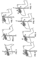
- FIGS. 5-11 are sequential views of a cylinder latch needle in a reverse plaiting circular knitting process, e.g. for use in forming an electric heating/warming composite fibrous article of the invention.
- FIG. 12 is a somewhat diagrammatic end section view of a preferred embodiment of a conductive yarn for an electric heating/warming fibrous article of the invention
- FIGS. 13-16 are similar views of alternative embodiments of conductive elements for fibrous electric heating/warming articles of the invention.
- FIG. 17 is a somewhat diagrammatic section view of a segment of a tubular knit body during knitting
- FIG. 18 is a somewhat diagrammatic perspective view of the tubular knit body of FIG. 17.
- FIG. 19 is an end section view, similar to FIG. 2, of a fibrous electric heating/warming article of the invention with fleece on both faces
- FIG. 20 is an enlarged, plan view of the technical face showing an alternative embodiment of a conductor element.
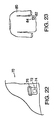
- FIGS. 21, 22 and 23 are somewhat diagrammatic representations of other embodiments of fibrous heating/warming articles of the invention, as adapted to be powered by direct current, e.g., an automobile warming or heating pad (FIG. 21), adapted to be powered from an automobile battery; and a stadium or camping blanket (FIG. 22) and a garment (FIG. 23), adapted to be powered from a battery replaceably mounted to the article.
- direct current e.g., an automobile warming or heating pad (FIG. 21), adapted to be powered from an automobile battery; and a stadium or camping blanket (FIG. 22) and a garment (FIG. 23), adapted to be powered from a battery replaceably mounted to the article.
- FIG. 24 is a somewhat diagrammatic sectional view of a segment of a tubular knit body knitted in a continuous web, to form multiple, alternating machine-direction panels or strips of regions with loops bounded by regions without loops; and
- FIG. 25 is a somewhat diagrammatic perspective view of the tubular knit body of FIG. 24.
- FIGS. 26 and 27 are somewhat diagrammatic plan views of segments of woven electric heating/warming articles of another embodiment of the invention.
- FIG. 28 is a somewhat diagrammatic plan view of a segment of a weft knit electric heating/warming article of another embodiment of the invention.
- FIGS. 29 and 30 are somewhat diagrammatic perspective views of other embodiments of electric heating/warming articles of the invention formed of two or more layers.
- a fibrous electric heating/warming composite article 10 of the invention e.g. an electric blanket, adapted to generate heat upon application of electrical power, consists of a fibrous body 12 having a technical back 14 and a technical face 16.
- the body 12 incorporates a plurality of spaced-apart electric resistance heating elements 18 extending between opposite edge regions 20, 21 of the body.
- the body 12 is formed by joining a stitch yarn 22 and a loop yarn 25 in a standard reverse plaiting circular knitting (terry knitting) process, e.g. as described in Knitting Technology, by David J. Spencer (Woodhead Publishing Limited, 2nd edition, 1996).
- terry knitting a standard reverse plaiting circular knitting process
- the stitch yarn 22 forms the technical face 16 of the resulting fibrous fabric body
- the loop yam 25 forms the opposite technical back 14, where it is formed into loops (25, FIG. 10) extending over the stitch yarn 22.
- the loop yarn 25 extends outwardly from the planes of both surfaces and, on the technical face 16, the loop yarn 25 covers the stitch yarn 22 (e.g., see FIG. 17).
- the loop yarn 25 protects the stitch yarn 22, including the conductive yarns 26 knitted into the fibrous fabric body in the stitch yarn position.
- the loop yarn 25 forming the technical back 14 of the fibrous knit fabric body 12 can be made of any synthetic or natural material.
- the cross section and luster of the fibers or the filament may be varied, e.g., as dictated by requirements of the intended end use.
- the loop yarn can be a spun yarn made by any available spinning technique, or a filament yarn made by extrusion.
- the loop yarn denier is typically between 40 denier to 300 denier.
- a preferred loop yarn is a 200/100 denier T-653 Type flat polyester filament, e.g. as available commercially from E.I. duPont de Nemours and Company, Inc., of Wilmington, Delaware.
- an electric resistance-heating member 18 in the form of a conductive yarn 26 is incorporated into the fabric body 12, e.g., in place of the stitch yarn 22.
- the conductive yarn 26 forming the electrical resistance heating elements 18 consists of a core 28 of insulating material, e.g. a polyester yam, about which extends an electrical conductive element 30, e.g. three filaments 31 of stainless steel wire (e.g. 316L stainless steel) wrapped helically about the core 28, and an outer covering 32 of insulating material, e.g.
- polyester yarns 33 (only a few of which are suggested in the drawings) helically wrapped about the core 28 and the filaments 31 of the electrical conductive element 30.
- the conductive yarn 26 is available, e.g., from Bekaert Fibre Technologies, Bekaert Corporation, of Marietta, Georgia, as yarn series VN14.
- conductive yarns in the conductive yarn are dependent, e.g., on end use requirements.
- a conductive yarn 26' has four filaments 31' wrapped about core 28' with an outer covering 32' of polyester yarns 33'; in FIG. 14, a conductive yarn 26" has three filaments 31" wrapped by outer covering 32" of polyester yarns 33", without a core.
- conductive yarns 37, 37', respectively are formed without an outer covering about the filaments 35, 35', respectively, wrapped about core 34, 34', respectively.
- the stitch yarn 22 and loop yarn 25 of the fabric body 12 serve to insulate the conductive yarns in the fibrous heating/warming fabric article.
- the resistivity of the conductive yarn can be selected in the range, e.g., of from about 0.1 ohm/cm to about 500 ohm/cm on the basis of end use requirements of the fibrous heating/warming fabric article 10.
- conductive yarns performing outside this range can also be employed, where required or desired.
- the core of the conductive yarn and the sheath material of the outer covering over the conductive filaments may be made of synthetic or natural material.
- the outer covering may also have the form of a sleeve, e.g. a dip-coated or extruded sleeve.
- Conductive yams of different constructions suitable for use according to this invention can also be obtained from Bekaert Fibre Technologies.
- the fibrous fabric body 12 is formed by reverse plaiting on a circular knitting machine. This is principally a terry knit, where the loops formed of the loop yarn 25 cover the stitch yarn 22 on the technical face 16 (see FIG. 17).
- the conductive yarn is incorporated into the fibrous knit fabric prebody formed on the circular knitting machine at a predetermined spacing or distance apart, D (FIG. 1), for uniform heating in the resulting heating/warming fabric article 10.
- the spacing is typically a function, e.g., of the requirements of heating, energy consumption and heat distribution in the article to be formed.
- the spacing of conductive yarns maybe in the range of from about 0.02 inch to about 2.5 inches.
- the conductive yarns may be spaced symmetrically from each other, or the conductive yarns may be spaced asymmetrically, with varying spacing, as desired.
- a preferred position of the conductive yarn is in the stitch position of the circular knitted construction.
- Series of conductive yarns may then be knit symmetrically, i.e., at a predetermined distance apart, in each repeat, i.e., the conductive yarn can be in stitch position at any feed repeat of the circular knitting machine.
- the feed position may be varied, and series of conductive yarns may be knit asymmetrically, with the yarns more closely or widely spaced, e.g., as desired or as appropriate to the intended product use. Again, the specific number of feeds, and the spacing of the conductive yarns, is dependent on the end use requirements.
- the power consumption for each conductive yarn is generally considerably lower than in the separate heating wires of prior art devices.
- the conductive yams in a fibrous fabric body of the invention can be placed relatively more closely together, with less susceptibility to hot spots.
- the edge regions 20, 21 may be formed as a panel 90 in the tubular knit body 92.
- the edge regions 20, 21 of the fibrous fabric body are preferably formed without loops, and in a manner such that the edge regions do not curl upon themselves, e.g. the edge region panel is formed by single lacoste or double lacoste knitting.
- the end portions 36 (FIG. 1) of the conductive yarns 26 extending into the flat, edge regions 20, 21 without loops are thus more easily accessible in the end regions for completing an electrical heating circuit, as described below.
- the fibrous tubular knit body 92 is removed from the knitting machine and slit, e.g., along a line of stitches in a "needle-out" region 94 marking the desired slit line, to create a planar fabric.
- the fibrous tubular knit body 92 may be slit on-line, e.g. by a cutting edge mounted to the knitting machine.
- the fibrous knitted fabric body 12 incorporating the electric resistance heating elements 18 in the form of the conductive yarns is next subjected to finishing.
- the fibrous fabric body 12 may go through processes of sanding, brushing, napping, etc., to generate a fleece 38.
- the fleece 38 may be formed in non-conductive fibers on one face of the fibrous fabric body 12 (FIG. 2), e.g., on the technical back 14, in the loop yarn, or a fleece 38, 38' maybe formed in non-conductive fibers on both faces of the fibrous fabric body 12' (FIG. 19), including on the technical face 16, in the overlaying loops of the loop yarn and/or in the stitch yarn.
- the process of generating the fleece on the face or faces of fabric body is preferably performed in a manner to avoid damage to the conductive yarn that is part of the construction of the fibrous fabric body 12.
- the fleece is formed in a manner that avoids damage to the conductive filaments of the conductive yarn that would result in an increase in resistance to the point of creating an undesirable local hot spot, or would sever the conductive yarn completely, which could result in undesirable increased electrical flow elsewhere in the circuit.
- the fabric body may also be treated, e.g. chemically, to render the material hydrophobic or hydrophilic.
- conductive buses 40 are provided in opposite edge regions 20, 21 (where, preferably, there are no loops on the surface) to connect the spaced apart electrical resistance heating elements 18, in parallel, to a source of electrical power, thereby to complete the electrical circuit.
- the conductive buses 40 may be formed or attached upon the technical back 14, as shown in FIG. 1, or they may instead be formed or attached upon the technical face 16, as seen in FIGS. 19 and 20. Any suitable method may be used to complete the circuit.
- the conductive bus 40 may, at least in part, be applied in the form of a conductive paste, e.g. such as available commercially from Loctite Corporation, of Rocky Hill, Connecticut.
- the conductive paste may be applied as a stripe to a surface of the fabric body 12 in electrical conductive relationship with the electrical resistance heating elements 18, and then connected to the power source.
- the conductive filaments of the electrical resistance heating elements 18 may be exposed, e.g., the polyester covering yarn may be removed with solvent or localized heat, e.g. by laser; the covering yarn may be manually unraveled; or the fabric body 12 may be formed with a needle out in the flat regions 20, 21, thus to facilitate accessibility to each of the conductive yarns.
- the conductive buses 40 in the form of conductive yarn or thread, are attached upon the surface of the fibrous fabric body 12, e.g., by stitching, e.g.
- the conductive bus 40' may consist of localized dots or regions 42 of conductive paste applied in electrical contact with exposed conductive filaments of the electric resistance heating elements 18, with a conductive metal wire 44 disposed in electrical conductive contact with, and extending, preferably continuously, between, the localized conductive paste regions 42.
- the electric conductive bus 40' is thereafter covered by a layer of fabric material 46 joined to overlay a portion or substantially all of the surface of the fabric body 12', e.g., in the form of a cloth trim or edging material attached, e.g., by stitching along the edge of the fabric body 12', or in the form of a second layer of fabric joined to fabric body 12', e.g., by stitching or lamination.
- the conductive bus 40 is preferably flexible, corrosion resistant, with low electrical resistivity, e.g. 0.1 ohm/meter to 100 ohm/meter, and mechanically durable. Other considerations include cost, availability in the market, and ease of fabrication.
- the conductive bus 40 may thus have the form of a wire, e.g., stranded, twisted, or braided; a conductive-coated textile, e.g., a coated filament or fabric, or a woven ribbon; a foil tape, e.g., adhesive backed, with or without a conductive backing; a conductive-filled resin, e.g., disposed in a continuous line; or a hybrid textile, e.g., including tinsel wire or stainless steel filaments, in twisted, braided, stranded, woven or knitted configuration
- the conductive bus 40 may also have the form of a single yarn, or two or more parallel yams, woven or knitted into or stitched upon the fabric body, or a tape or band of conductive material attached upon the surface of the fabric.
- the conductive bus 40 may be a narrow woven element. incorporating silver-coated copper tinsel wire, either multi-strand or individual strands in parallel, with periodic floats provided for contact with the conductive yarns, or a narrow woven element pre-coated with conductive thermoplastic in a stripe pattern, with discontinuous diagonal stripes to provide flexibility and ensure registration with conductive yarns.
- the conductive bus 40 may also extend in multiple elements extending generally parallel in the edge region of the fabric, with similar or different lengths, to connect to distinct sets of conductive yarns, in this manner reducing the level of electrical current carried by each conductive bus element in the region close to the source of electrical power. In the case of conductive buses of different lengths, the resistivity of the individual conductive bus elements may be different.
- the conductive bus 40 is preferably mounted upon the surface of the fabric body in a manner to provide strain relief.
- strain relief attachment may be provided by sewing the conductive bus to the fabric, by tacking the conductive bus to the fabric body with mechanical fasteners, such as snaps, grommets, staples, or rivets; by over-molding in place strain relief injection-molded "buttons"; or by incorporating strain relief and electrical connection rigid filled resin having low viscosity.
- the conductive yarns 18 and conductive bus 40 may be connected electrically by conductive welding or paste; rivets, snaps, or metal holders or fasteners; interlacing, knitting or weaving in, or combinations of the above.
- a fibrous electric heating/warming fabric article 10 of the invention (an electric blanket) is adapted for connection to a source of alternating current by means of plug 50 on cord 51 for insertion in household outlet 52.
- a fibrous warming or heating pad 60 of the invention e.g. for an automobile seat, is adapted for connection to a source of direct current by means of plug 62 on cord 64 for insertion into the cigarette lighter or other power outlet 66 of an automobile.
- fibrous, multi-layer heating/warming fabric articles 140, 150 consist of at least two layers of fibrous fabric 142, 144 and 152, 154, respectively.
- these layers of fibrous fabric have outer surfaces 143, 145 and 153, 155, respectively, fibers of one or both of which may be raised or fleece, and smooth (non-fleece), opposed inner surfaces 143', 145' and 153', 155',respectively, with a heating/warming circuit of the invention (represented by dashed lines 160, 170, respectively) disposed therebetween.
- a heating/warming circuit of the invention represented by dashed lines 160, 170, respectively
- the fibrous heating/warming fabric article 162 may be of the form described in our co-pending patent application U.S. Serial No. 09/592,235, filed June 12, 2000 and entitled "Electric Resistance Heating/Warming Articles," with the heating/warming circuit 160 formed of conductive yarns disposed and secured upon the surface of the fibrous fabric article 162 and extending between conductive buses at opposite edge regions.
- the conductive yarns may be fastened upon the surface, e.g., in embroidery stitches or sewing, by adhesive, or by mechanical locking.
- the resulting product is a fibrous electric blanket, e.g., 90 inches by 90 inches with a 24-volt power supply, with features not available with blankets currently on the market.
- the fibrous blanket has the characteristics of being: flexible, foldable, portable, able to be washed frequently, comfortable, with zone heating and low voltage (for increased safety).
- fibrous electric heating/warming articles of the invention may be formed by any suitable method that results in a fibrous body formed of non-conductive fibers and conductive elements capable of generating heating/warming when connected to a source of electrical power, the non-conductive fibers being exposed for finishing at one or both surfaces to create fleece, the finishing being performed in a manner to avoid damage to electrical conductivity performance of the conductive elements joined with the non-conductive fibers in the fibrous body.
- the fibrous body may be formed, e.g., by knitting, weaving, tufting or needling, felting, laying up or otherwise forming a non-woven web, or any other suitable process.
- the fibrous tubular knit body 100 can also be slit on-line, to create multiple panels of planar fabric, each panel having a central region 108 with loops bounded by opposite edge regions 110, 112 without loops.
- Each of the narrow panels of fibrous fabric can then be processed to form relatively narrow fibrous electric heating/warming fabric articles of the invention, e.g. personal heating pads or the like, e.g., by severing in a direction generally transverse to the continuous web direction.
Landscapes
- Engineering & Computer Science (AREA)
- Textile Engineering (AREA)
- Environmental & Geological Engineering (AREA)
- Health & Medical Sciences (AREA)
- General Health & Medical Sciences (AREA)
- Physical Education & Sports Medicine (AREA)
- Surface Heating Bodies (AREA)
Applications Claiming Priority (2)
| Application Number | Priority Date | Filing Date | Title |
|---|---|---|---|
| US09/791,237 US6414286B2 (en) | 1999-04-22 | 2001-02-23 | Electric heating/warming fibrous articles |
| US791237 | 2001-02-23 |
Publications (1)
| Publication Number | Publication Date |
|---|---|
| EP1234903A1 true EP1234903A1 (fr) | 2002-08-28 |
Family
ID=25153071
Family Applications (1)
| Application Number | Title | Priority Date | Filing Date |
|---|---|---|---|
| EP01309102A Withdrawn EP1234903A1 (fr) | 2001-02-23 | 2001-10-26 | Articles fibreux chauffants/réchauffants électriquement |
Country Status (2)
| Country | Link |
|---|---|
| US (1) | US6414286B2 (fr) |
| EP (1) | EP1234903A1 (fr) |
Cited By (3)
| Publication number | Priority date | Publication date | Assignee | Title |
|---|---|---|---|---|
| US8585606B2 (en) | 2010-09-23 | 2013-11-19 | QinetiQ North America, Inc. | Physiological status monitoring system |
| US9028404B2 (en) | 2010-07-28 | 2015-05-12 | Foster-Miller, Inc. | Physiological status monitoring system |
| US9211085B2 (en) | 2010-05-03 | 2015-12-15 | Foster-Miller, Inc. | Respiration sensing system |
Families Citing this family (30)
| Publication number | Priority date | Publication date | Assignee | Title |
|---|---|---|---|---|
| FR2819942B1 (fr) * | 2001-01-19 | 2003-05-30 | Cloirec Pierre Le | Dispositif pour contact electrique pour materiaux fibreux et son uitilisation pour le chauffage par effet joule |
| US20090184107A1 (en) * | 2001-09-03 | 2009-07-23 | Michael Weiss | Heating element with stranded contact |
| US6843078B2 (en) * | 2002-01-25 | 2005-01-18 | Malden Mills Industries, Inc. | EMI shielding fabric |
| AU2003221825A1 (en) * | 2002-04-05 | 2003-10-27 | Vikram Sharma | Tubular knit fabric and system |
| US6888108B2 (en) | 2002-10-11 | 2005-05-03 | Perfect Fit Industries, Inc. | Low voltage power supply system for an electric blanket or the like |
| US6713724B1 (en) | 2002-10-11 | 2004-03-30 | Perfect Fit Industries, Inc. | Heating element arrangement for an electric blanket or the like |
| US20040070904A1 (en) * | 2002-10-11 | 2004-04-15 | Carr Sheldon P. | Over-voltage protection arrangement for a low voltage power supply |
| TW567077B (en) * | 2002-12-19 | 2003-12-21 | King S Metal Fiber Technologie | Wearable electrode apparatus and manufacture thereof |
| US7038177B2 (en) * | 2003-09-08 | 2006-05-02 | Malden Mills Industries, Inc. | Electric heating/warming fabric articles |
| US20050244587A1 (en) * | 2003-09-09 | 2005-11-03 | Shirlin Jack W | Heating elements deposited on a substrate and related method |
| US6946628B2 (en) * | 2003-09-09 | 2005-09-20 | Klai Enterprises, Inc. | Heating elements deposited on a substrate and related method |
| US20050095406A1 (en) * | 2003-10-31 | 2005-05-05 | Gunzel Edward C. | Attachment of cables to flexible fabrics |
| US7025596B2 (en) * | 2004-06-14 | 2006-04-11 | Motorola, Inc. | Method and apparatus for solder-less attachment of an electronic device to a textile circuit |
| US20060191911A1 (en) * | 2005-01-14 | 2006-08-31 | Noble Fiber Technologies, Inc. | Blanket with metal coated filaments for heating |
| EP1929839A2 (fr) * | 2005-08-22 | 2008-06-11 | Thermosiv Ltd. | Armature chauffante souple |
| US20070089800A1 (en) * | 2005-10-24 | 2007-04-26 | Sensatex, Inc. | Fabrics and Garments with Information Infrastructure |
| US20080245786A1 (en) * | 2006-10-03 | 2008-10-09 | Cozpets Llc | System and method for providing an asymmetrically or symmetrically distributed multi/single zone woven heated fabric system having an integrated bus |
| US7716815B2 (en) * | 2007-10-12 | 2010-05-18 | Bariaq Co., Ltd | Process for fabricating a cloth-like heating element with two pairs of electrical conductors and parallel circuits |
| US8166326B2 (en) * | 2007-11-08 | 2012-04-24 | International Business Machines Corporation | Managing power consumption in a computer |
| TW200925344A (en) * | 2007-12-12 | 2009-06-16 | Everest Textile Co Ltd | Electric heating fabric device |
| CN102046864B (zh) * | 2008-05-28 | 2013-06-12 | 瑟尔瑞株式会社 | 导电垫及其制造方法 |
| DE102009052929B4 (de) * | 2009-11-12 | 2011-12-08 | Kunert Fashion Gmbh & Co. Kg | Strickware mit Feuchtigkeitssensor |
| CA2836312C (fr) | 2011-06-01 | 2017-03-14 | Saint-Gobain Adfors Canada, Ltd. | Bande de cloison seche de renfort multidirectionnelle |
| US9752259B2 (en) * | 2012-04-09 | 2017-09-05 | The Hong Kong Research Intitute Of Textiles And Apparel Limited | Stretchable electrical interconnect and method of making same |
| US9301341B2 (en) | 2013-03-14 | 2016-03-29 | Chromalox, Inc. | Medium voltage heating element assembly |
| US9327838B2 (en) * | 2013-05-14 | 2016-05-03 | Sikorsky Aircraft Corporation | On-blade deice heater mat |
| US9523285B2 (en) | 2013-12-13 | 2016-12-20 | Chromalox, Inc. | Energy storage systems with medium voltage electrical heat exchangers |
| CN108007969A (zh) * | 2016-10-27 | 2018-05-08 | 丽宝大数据股份有限公司 | 织物及其制作方法 |
| JP2019150232A (ja) * | 2018-03-01 | 2019-09-12 | ロレアル | 可撓性加熱装置 |
| CN108374228B (zh) * | 2018-04-27 | 2020-03-03 | 织暖有限公司 | 一种具有发热功能的扁机编织物及其编织工艺 |
Citations (4)
| Publication number | Priority date | Publication date | Assignee | Title |
|---|---|---|---|---|
| US3232080A (en) * | 1964-08-11 | 1966-02-01 | Inui Toshiaki | Carpet interwoven with heating wire |
| EP0532468A1 (fr) * | 1991-09-11 | 1993-03-17 | TECNIT-Technische Textilien und Systeme GmbH | Elément chauffant électrique |
| EP0548574A2 (fr) * | 1991-12-23 | 1993-06-30 | I.G. Bauerhin GmbH elektro-technische Fabrik | Elément chauffant pour surface et méthode de fabrication |
| EP1049354A1 (fr) * | 1999-04-22 | 2000-11-02 | Malden Mills Industries, Inc. | Articles d'étoffe chauffant électriquement |
Family Cites Families (50)
| Publication number | Priority date | Publication date | Assignee | Title |
|---|---|---|---|---|
| US1553461A (en) | 1922-04-24 | 1925-09-15 | Negromanti Antonio | Thermoelectric fabric and process for the manufacture of same |
| US1744327A (en) | 1927-08-11 | 1930-01-21 | Moore David Pelton | Knitted pile fabric |
| US1965542A (en) | 1933-11-24 | 1934-07-03 | Jr William Colvin | Fabric |
| US2025586A (en) | 1934-08-28 | 1935-12-24 | Gen Electric | Electrically heated rug |
| US2203918A (en) | 1939-03-07 | 1940-06-11 | Nashua Mfg Company | Electrically heated blanket |
| US2392470A (en) | 1943-09-11 | 1946-01-08 | Therm A Mode Company Inc | Thermal fabric |
| US2381218A (en) | 1944-05-30 | 1945-08-07 | Benjamin Liebowitz | Pile fabric |
| US2458801A (en) | 1944-08-22 | 1949-01-11 | Knapp Monarch Co | Electrically energizable fabric |
| US2432785A (en) | 1945-01-08 | 1947-12-16 | Ivar O Moberg | Electrically heated two-ply blanket |
| US2581212A (en) | 1949-05-04 | 1952-01-01 | Gen Electric | Electrically heated fabric |
| US2670620A (en) | 1950-08-29 | 1954-03-02 | Goldstaub Henry Herbert | Flexible electric heating element |
| GB783883A (en) | 1954-06-03 | 1957-10-02 | Antonio Negromanti | Improvements relating to electrically heated fabrics, particularly suitable for padsand blankets |
| US2945115A (en) | 1956-07-19 | 1960-07-12 | Edward W Weitzel | Knitted hair drying cap |
| US3478422A (en) | 1965-09-07 | 1969-11-18 | Toshiaki Inui | Method of making an electric blanket |
| US3528874A (en) | 1965-10-11 | 1970-09-15 | West Point Pepperell Inc | Heat-insulating fabric and method of preparing it |
| NL134709C (fr) | 1966-12-16 | |||
| US3513297A (en) | 1967-05-31 | 1970-05-19 | Gulton Ind Inc | Heat radiating articles |
| US3721799A (en) | 1969-10-22 | 1973-03-20 | R Carlstrom | Electric heating source for seats and mattresses and methods of application of the same |
| US3859506A (en) | 1973-06-15 | 1975-01-07 | Sola Basic Ind Inc | Constant wattage heating element |
| US4021640A (en) | 1975-07-30 | 1977-05-03 | Comfort Products, Inc. | Insulated glove construction |
| US4063069A (en) | 1976-03-03 | 1977-12-13 | Menachem Peeri | Electrically heatable floor carpet |
| US4250397A (en) | 1977-06-01 | 1981-02-10 | International Paper Company | Heating element and methods of manufacturing therefor |
| US4245149A (en) | 1979-04-10 | 1981-01-13 | Fairlie Ian F | Heating system for chairs |
| GB2050946B (en) | 1979-05-30 | 1983-02-16 | Tdk Electronics Co Ltd | Hot melt screen printing machine and process for producing a screen printing plate |
| US4375009A (en) | 1980-12-10 | 1983-02-22 | Hewlett-Packard Company | Shielded electrical cable |
| CH662231A5 (de) | 1982-09-13 | 1987-09-15 | Eilentropp Hew Kabel | Flexibles elektrisches ablaengbares heiz- oder temperaturmesselement. |
| US4459461A (en) | 1982-09-28 | 1984-07-10 | West Point Pepperell, Inc. | Flocked electric blanket construction |
| JPS59108291A (ja) | 1982-12-11 | 1984-06-22 | 佐藤 亮拿 | 面発熱体 |
| DE3313011A1 (de) | 1983-04-12 | 1984-10-18 | Girmes-Werke Ag, 4155 Grefrath | Heizelement fuer textilien |
| US4607154A (en) | 1983-09-26 | 1986-08-19 | Fieldcrest Mills, Inc. | Electrical heating apparatus protected against an overheating condition and a temperature sensitive electrical sensor for use therewith |
| US4577094A (en) | 1983-10-05 | 1986-03-18 | Fieldcrest Mills, Inc. | Electrical heating apparatus protected against an overheating condition |
| US4564745A (en) | 1984-02-24 | 1986-01-14 | Geant Entrepeneur Electrique Ltee | Pre-cast heating panel |
| JPS60258884A (ja) | 1984-06-06 | 1985-12-20 | 松下電器産業株式会社 | 就寝用採暖具 |
| US4736088A (en) | 1985-07-18 | 1988-04-05 | Battle Creek Equipment Company | Therapeutic heating pad and muff structure |
| JPS62100968A (ja) | 1985-10-29 | 1987-05-11 | 東レ株式会社 | 糸状発熱体及びその製造方法 |
| JPH0743991Y2 (ja) | 1986-09-02 | 1995-10-09 | ダイキン工業株式会社 | 面状発熱体の電極構造 |
| US5081341A (en) | 1988-08-29 | 1992-01-14 | Specialty Cable Corp. | Electrical heating element for use in a personal comfort device |
| US5364678A (en) | 1989-10-17 | 1994-11-15 | Malden Mills Industries, Inc. | Windproof and water resistant composite fabric with barrier layer |
| JP2934046B2 (ja) | 1991-03-22 | 1999-08-16 | 帝人株式会社 | タイヤウオーマー |
| US5073688A (en) | 1991-04-01 | 1991-12-17 | Mccormack William C | Body temperature responsive transport warming blanket |
| US5484983A (en) | 1991-09-11 | 1996-01-16 | Tecnit-Techische Textilien Und Systeme Gmbh | Electric heating element in knitted fabric |
| US5321960A (en) | 1993-01-28 | 1994-06-21 | Kayser-Roth Corporation | Abrasion resistant reinforced fabric |
| US5319950A (en) | 1993-02-22 | 1994-06-14 | Kayser-Roth Corporation | Abrasion resistant reinforced fabric |
| JP3037525B2 (ja) | 1993-04-12 | 2000-04-24 | 松下電器産業株式会社 | 発熱シート |
| KR950013314A (ko) | 1993-10-13 | 1995-05-17 | 유끼꼬 하야시 | 면상 감열소자 및 그것을 가진 면상 히이터 |
| US5412181A (en) | 1993-12-27 | 1995-05-02 | The B. F. Goodrich Company | Variable power density heating using stranded resistance wire |
| JP3006758U (ja) | 1994-05-13 | 1995-01-31 | 帝人株式会社 | ロードヒーター |
| US5679277A (en) | 1995-03-02 | 1997-10-21 | Niibe; Akitoshi | Flame-resistant heating body and method for making same |
| US5918319A (en) | 1996-07-22 | 1999-07-06 | Baxter; Hal Thomas | Protective garment incorporating an abrasion-resistant fabric |
| US5977517A (en) | 1998-07-09 | 1999-11-02 | Grosjean; Douglas Martin | Electrically heated vest |
-
2001
- 2001-02-23 US US09/791,237 patent/US6414286B2/en not_active Expired - Fee Related
- 2001-10-26 EP EP01309102A patent/EP1234903A1/fr not_active Withdrawn
Patent Citations (4)
| Publication number | Priority date | Publication date | Assignee | Title |
|---|---|---|---|---|
| US3232080A (en) * | 1964-08-11 | 1966-02-01 | Inui Toshiaki | Carpet interwoven with heating wire |
| EP0532468A1 (fr) * | 1991-09-11 | 1993-03-17 | TECNIT-Technische Textilien und Systeme GmbH | Elément chauffant électrique |
| EP0548574A2 (fr) * | 1991-12-23 | 1993-06-30 | I.G. Bauerhin GmbH elektro-technische Fabrik | Elément chauffant pour surface et méthode de fabrication |
| EP1049354A1 (fr) * | 1999-04-22 | 2000-11-02 | Malden Mills Industries, Inc. | Articles d'étoffe chauffant électriquement |
Cited By (3)
| Publication number | Priority date | Publication date | Assignee | Title |
|---|---|---|---|---|
| US9211085B2 (en) | 2010-05-03 | 2015-12-15 | Foster-Miller, Inc. | Respiration sensing system |
| US9028404B2 (en) | 2010-07-28 | 2015-05-12 | Foster-Miller, Inc. | Physiological status monitoring system |
| US8585606B2 (en) | 2010-09-23 | 2013-11-19 | QinetiQ North America, Inc. | Physiological status monitoring system |
Also Published As
| Publication number | Publication date |
|---|---|
| US20010022298A1 (en) | 2001-09-20 |
| US6414286B2 (en) | 2002-07-02 |
Similar Documents
| Publication | Publication Date | Title |
|---|---|---|
| EP1201806B1 (fr) | Articles en étoffe chauffants/réchauffants électriquement | |
| US6414286B2 (en) | Electric heating/warming fibrous articles | |
| EP1049354B1 (fr) | Articles d'étoffe chauffant électriquement | |
| US6888112B2 (en) | Electric heating/warming woven fibrous articles | |
| US7038177B2 (en) | Electric heating/warming fabric articles | |
| US6723967B2 (en) | Heating/warming textile articles with phase change components | |
| US20080245786A1 (en) | System and method for providing an asymmetrically or symmetrically distributed multi/single zone woven heated fabric system having an integrated bus | |
| TW200925344A (en) | Electric heating fabric device | |
| EP2232944A1 (fr) | Système et procédé pour fournir un système de tissu chauffé multizone/monozone à répartition asymétrique ou symétrique à bus intégré | |
| KR20150078804A (ko) | 도전성 면상체 및 그 제조방법 | |
| AU8364501A (en) | Electric heating/warming fabric articles | |
| IT201800010666A1 (it) | Coprimaterasso termico o coperta termica | |
| KR20140084818A (ko) | 전원공급 및 신호전달선을 일체로 구비한 면상도전체 | |
| KR20140083841A (ko) | 면상도전체의 도전성 선재 배치구조 | |
| JPS61172732A (ja) | 被覆導電性シ−ト材 | |
| JP2014008377A (ja) | 車両構成部材の表皮材 |
Legal Events
| Date | Code | Title | Description |
|---|---|---|---|
| PUAI | Public reference made under article 153(3) epc to a published international application that has entered the european phase |
Free format text: ORIGINAL CODE: 0009012 |
|
| AK | Designated contracting states |
Kind code of ref document: A1 Designated state(s): AT BE CH CY DE DK ES FI FR GB GR IE IT LI LU MC NL PT SE TR |
|
| AX | Request for extension of the european patent |
Free format text: AL;LT;LV;MK;RO;SI |
|
| 17P | Request for examination filed |
Effective date: 20030227 |
|
| AKX | Designation fees paid |
Designated state(s): AT BE CH CY DE DK ES FI FR GB GR IE IT LI LU MC NL PT SE TR |
|
| 17Q | First examination report despatched |
Effective date: 20041014 |
|
| STAA | Information on the status of an ep patent application or granted ep patent |
Free format text: STATUS: THE APPLICATION IS DEEMED TO BE WITHDRAWN |
|
| 18D | Application deemed to be withdrawn |
Effective date: 20050426 |