EP3244785B1 - Appareil d'aspiration et procédé permettant de faire fonctionner un appareil d'aspiration - Google Patents
Appareil d'aspiration et procédé permettant de faire fonctionner un appareil d'aspiration Download PDFInfo
- Publication number
- EP3244785B1 EP3244785B1 EP15706470.0A EP15706470A EP3244785B1 EP 3244785 B1 EP3244785 B1 EP 3244785B1 EP 15706470 A EP15706470 A EP 15706470A EP 3244785 B1 EP3244785 B1 EP 3244785B1
- Authority
- EP
- European Patent Office
- Prior art keywords
- port
- region
- wall
- perforated plate
- air
- Prior art date
- Legal status (The legal status is an assumption and is not a legal conclusion. Google has not performed a legal analysis and makes no representation as to the accuracy of the status listed.)
- Active
Links
- 238000000034 method Methods 0.000 title claims description 16
- 238000004140 cleaning Methods 0.000 claims description 56
- 230000009467 reduction Effects 0.000 claims description 10
- 230000008569 process Effects 0.000 claims description 9
- 239000000463 material Substances 0.000 claims description 7
- 239000012530 fluid Substances 0.000 claims description 6
- 230000009471 action Effects 0.000 claims description 4
- 230000008878 coupling Effects 0.000 claims description 3
- 238000010168 coupling process Methods 0.000 claims description 3
- 238000005859 coupling reaction Methods 0.000 claims description 3
- 239000003570 air Substances 0.000 description 140
- 230000002349 favourable effect Effects 0.000 description 13
- 238000010521 absorption reaction Methods 0.000 description 12
- 238000013461 design Methods 0.000 description 6
- 230000000694 effects Effects 0.000 description 4
- 239000012080 ambient air Substances 0.000 description 3
- 238000004891 communication Methods 0.000 description 3
- XEEYBQQBJWHFJM-UHFFFAOYSA-N iron Substances [Fe] XEEYBQQBJWHFJM-UHFFFAOYSA-N 0.000 description 3
- 230000004048 modification Effects 0.000 description 3
- 238000012986 modification Methods 0.000 description 3
- 239000006096 absorbing agent Substances 0.000 description 2
- 239000011358 absorbing material Substances 0.000 description 2
- 230000008859 change Effects 0.000 description 2
- 238000005516 engineering process Methods 0.000 description 2
- 229910052742 iron Inorganic materials 0.000 description 2
- 238000004519 manufacturing process Methods 0.000 description 2
- 239000002557 mineral fiber Substances 0.000 description 2
- 210000002268 wool Anatomy 0.000 description 2
- HBBGRARXTFLTSG-UHFFFAOYSA-N Lithium ion Chemical compound [Li+] HBBGRARXTFLTSG-UHFFFAOYSA-N 0.000 description 1
- 230000006978 adaptation Effects 0.000 description 1
- 238000004887 air purification Methods 0.000 description 1
- 230000002238 attenuated effect Effects 0.000 description 1
- 230000004888 barrier function Effects 0.000 description 1
- 238000011109 contamination Methods 0.000 description 1
- 238000001816 cooling Methods 0.000 description 1
- 238000012937 correction Methods 0.000 description 1
- 238000013016 damping Methods 0.000 description 1
- 239000000428 dust Substances 0.000 description 1
- 238000001914 filtration Methods 0.000 description 1
- 230000001771 impaired effect Effects 0.000 description 1
- 150000002505 iron Chemical class 0.000 description 1
- 229910001416 lithium ion Inorganic materials 0.000 description 1
- 239000002245 particle Substances 0.000 description 1
- 238000003825 pressing Methods 0.000 description 1
- 238000000746 purification Methods 0.000 description 1
- 239000007787 solid Substances 0.000 description 1
- 238000012549 training Methods 0.000 description 1
- 230000007704 transition Effects 0.000 description 1
Images


Classifications
-
- A—HUMAN NECESSITIES
- A47—FURNITURE; DOMESTIC ARTICLES OR APPLIANCES; COFFEE MILLS; SPICE MILLS; SUCTION CLEANERS IN GENERAL
- A47L—DOMESTIC WASHING OR CLEANING; SUCTION CLEANERS IN GENERAL
- A47L9/00—Details or accessories of suction cleaners, e.g. mechanical means for controlling the suction or for effecting pulsating action; Storing devices specially adapted to suction cleaners or parts thereof; Carrying-vehicles specially adapted for suction cleaners
- A47L9/0081—Means for exhaust-air diffusion; Means for sound or vibration damping
-
- A—HUMAN NECESSITIES
- A47—FURNITURE; DOMESTIC ARTICLES OR APPLIANCES; COFFEE MILLS; SPICE MILLS; SUCTION CLEANERS IN GENERAL
- A47L—DOMESTIC WASHING OR CLEANING; SUCTION CLEANERS IN GENERAL
- A47L9/00—Details or accessories of suction cleaners, e.g. mechanical means for controlling the suction or for effecting pulsating action; Storing devices specially adapted to suction cleaners or parts thereof; Carrying-vehicles specially adapted for suction cleaners
- A47L9/20—Means for cleaning filters
-
- A—HUMAN NECESSITIES
- A47—FURNITURE; DOMESTIC ARTICLES OR APPLIANCES; COFFEE MILLS; SPICE MILLS; SUCTION CLEANERS IN GENERAL
- A47L—DOMESTIC WASHING OR CLEANING; SUCTION CLEANERS IN GENERAL
- A47L9/00—Details or accessories of suction cleaners, e.g. mechanical means for controlling the suction or for effecting pulsating action; Storing devices specially adapted to suction cleaners or parts thereof; Carrying-vehicles specially adapted for suction cleaners
- A47L9/28—Installation of the electric equipment, e.g. adaptation or attachment to the suction cleaner; Controlling suction cleaners by electric means
- A47L9/2868—Arrangements for power supply of vacuum cleaners or the accessories thereof
- A47L9/2884—Details of arrangements of batteries or their installation
-
- F—MECHANICAL ENGINEERING; LIGHTING; HEATING; WEAPONS; BLASTING
- F16—ENGINEERING ELEMENTS AND UNITS; GENERAL MEASURES FOR PRODUCING AND MAINTAINING EFFECTIVE FUNCTIONING OF MACHINES OR INSTALLATIONS; THERMAL INSULATION IN GENERAL
- F16K—VALVES; TAPS; COCKS; ACTUATING-FLOATS; DEVICES FOR VENTING OR AERATING
- F16K17/00—Safety valves; Equalising valves, e.g. pressure relief valves
- F16K17/02—Safety valves; Equalising valves, e.g. pressure relief valves opening on surplus pressure on one side; closing on insufficient pressure on one side
- F16K17/04—Safety valves; Equalising valves, e.g. pressure relief valves opening on surplus pressure on one side; closing on insufficient pressure on one side spring-loaded
- F16K17/042—Safety valves; Equalising valves, e.g. pressure relief valves opening on surplus pressure on one side; closing on insufficient pressure on one side spring-loaded with locking or disconnecting arrangements
-
- F—MECHANICAL ENGINEERING; LIGHTING; HEATING; WEAPONS; BLASTING
- F16—ENGINEERING ELEMENTS AND UNITS; GENERAL MEASURES FOR PRODUCING AND MAINTAINING EFFECTIVE FUNCTIONING OF MACHINES OR INSTALLATIONS; THERMAL INSULATION IN GENERAL
- F16K—VALVES; TAPS; COCKS; ACTUATING-FLOATS; DEVICES FOR VENTING OR AERATING
- F16K31/00—Actuating devices; Operating means; Releasing devices
- F16K31/02—Actuating devices; Operating means; Releasing devices electric; magnetic
- F16K31/06—Actuating devices; Operating means; Releasing devices electric; magnetic using a magnet, e.g. diaphragm valves, cutting off by means of a liquid
- F16K31/0644—One-way valve
- F16K31/0655—Lift valves
-
- B—PERFORMING OPERATIONS; TRANSPORTING
- B01—PHYSICAL OR CHEMICAL PROCESSES OR APPARATUS IN GENERAL
- B01D—SEPARATION
- B01D46/00—Filters or filtering processes specially modified for separating dispersed particles from gases or vapours
- B01D46/66—Regeneration of the filtering material or filter elements inside the filter
- B01D46/70—Regeneration of the filtering material or filter elements inside the filter by acting counter-currently on the filtering surface, e.g. by flushing on the non-cake side of the filter
Definitions
- the invention relates to a suction device, comprising a suction unit, a dirt collecting container, a filter device, wherein the dirt collecting container is in fluid communication with the suction unit via the filter device, and a cleaning device for the filter device, which has an external air valve device.
- the invention further relates to a method for operating a suction device, wherein the suction device comprises a suction unit, a dirt collecting container, a filter device, wherein the dirt collecting container is in flow communication with the suction unit via the filter device, and a cleaning device for the filter device, which has an external air valve device.
- WO 2012/107103 A1 a method for cleaning a filter of a vacuum cleaner is described in which increases the suction power of a suction unit for a transition of an external air valve in an open valve position and is later reduced again.
- the invention has for its object to provide a suction device of the type mentioned, in which an effective filter cleaning is achieved.
- At least one guide channel is provided for air, which has a first connection which is in fluid-effective connection with the cleaning device for providing external air from the at least one guide channel, a second connection for coupling of exhaust air of the suction unit has in the at least one guide channel, and having a third connection, which in fluidly effective connection is with the environment of the suction device, wherein via the third port, air from the environment in the at least one guide channel can be flowed.
- exhaust air is used as a foreign air targeted for a cleaning process of the filter device.
- the exhaust air is selectively guided and provided at the first port.
- the at least one guide channel provides a type of bypass for an exhaust air duct.
- the exhaust air is already provided with positive pressure from the suction unit. There is usually a corresponding volume flow, with a corresponding overpressure prevails. It can thereby achieve an effective cleaning.
- Exhaust air is already filtered air. It is usually less polluted than ambient air. As a result, backwashed air is again cleaner. It can be achieved an increase in the life of the suction unit.
- the additional coupling of air from the environment via the third port in the at least one guide channel can reduce the flow resistance and it is achieved an effective cleaning.
- the third connection is designed such that exhaust air from the suction unit can be discharged into the environment on it. It can then be carried out exhaust air from the first port to the third port and discharged there to the environment, the exhaust air on the first port flows past and then the filter cleaning process is available as external air.
- the at least one guide channel extends between the second connection and the third connection.
- a guidance of air between the second port and the third port can be achieved.
- a guidance of air is achieved at least from the third port to the first port.
- first connection is positioned relative to a flow guide and / or geometrically between the second connection and the third connection and in particular at least approximately centrally between the second connection and the third connection.
- a geometric intermediate positioning means that a connecting line between the second terminal and the third terminal passes through the first terminal or passes through a center plane of the first terminal. This makes it possible to achieve a symmetrized flow guidance on a housing of the suction device. It is possible to realize an effective filter cleaning.
- the at least one guide channel has a first region with a first extension axis on which the second connection lies, has a second region with a second extension axis on which the first connection lies, and has a third region with a third extension axis on which the third connection lies, wherein the first extension axis and / or the third extension axis are oriented transversely and in particular perpendicular to the second extension axis and in particular the first connection and the second connection are at different heights and / or the first connection and third connection at different heights.
- the first region and / or the third region are arranged laterally next to the cleaning device or filter device.
- the at least one guide channel is arranged or formed at least partially on a housing region which covers the dirt collecting container and / or the filter device and / or the cleaning device.
- the at least one guide channel and the second connection are formed so that the exhaust air of the suction unit completely enters the at least one guide channel.
- exhaust air is passed completely past the first connection. This results in an effective cleaning function.
- a good noise reduction can be achieved with appropriate guidance of the flow.
- the exhaust air coupled in via the second connection then, if no filter purification process is carried out, completely exits at the third connection into the environment.
- the at least one guide channel and the third connection are formed such that exhaust air from the suction unit can be released outside of a cleaning process of the filter device only at the third connection to the environment.
- a first inflow region for air to the first port is provided, which is formed between the second port and the first port, and a second inflow region is provided, which is formed between the third port and the first port.
- Exhaust air from the suction unit can be provided as external air via the first inflow region.
- Air from the environment can be provided as external air via the second inflow region. If, for example, no or insufficient exhaust air is available (because, for example, a suction hose is clogged), then air from the environment can at least temporarily serve as external air. If both exhaust air and air from the Environment is ready, then can be correspondingly lower the flow resistance. This can for example contribute to noise minimization.
- a fourth connection for exhaust air of the suction unit is arranged on the at least one guide channel. This makes it possible, for example, to achieve a symmetrical guidance for exhaust air with respect to the first port. In particular, at different points of the at least one guide channel exhaust air can be coupled into this.
- a fifth connection to the environment is arranged on the at least one guide channel. It can then enter at a different location than at the third port air from the environment in the at least one guide channel.
- a symmetrical guidance with respect to exhaust air and air from the environment can be achieved.
- the filter device and / or the cleaning device are geometrically positioned between the third connection and the fifth connection.
- a connecting line between the third connection and the fifth connection then passes through the filter device or the cleaning device. This makes it possible to achieve a symmetrized structure with symmetrized air flow with respect to the cleaning device.
- connection and the fifth connection are positioned on opposite sides of the housing. It can be achieved with simple design means an optimized and in particular symmetrized flow guidance.
- the at least one guide channel prefferably be mirror-symmetrical with respect to the third terminal and the fifth terminal and / or the first terminal and the fourth terminal, wherein in particular the first terminal is located on a mirror plane. This results in a symmetrized flow guidance.
- the fifth terminal is located on a same housing side area as the second terminal and the fourth terminal is located on a same housing side area as the third terminal. As a result, a symmetrized flow guidance can be achieved.
- a first inflow region for air is formed to the first port, which is formed between the second port and the first port, there is formed a second inflow region, which is formed between the third port and the first port, it is a third inflow region provided, which is formed between the fourth port and the first port, and there is provided a fourth inflow region, which is formed between the fifth port and the first port, wherein in particular the first inflow region and the third inflow region are mirror-symmetrical to each other and in particular the second Inflow region and the fourth inflow region are mirror-symmetrical to each other. It can thereby achieve a symmetrized flow guidance.
- the first connection is provided with sufficient external air.
- the cleaning device is associated with sound effect at least one perforated plate resonator, the at least one perforated plate resonator having a chamber with a chamber space and a chamber wall and at least one perforated plate which covers the chamber space.
- a perforated plate resonator (perforated plate absorber) has a resonator space over the chamber space, which is bounded on one side in particular by a perforated plate.
- noises can be effectively reduced by sound absorption, especially in the low frequency range (in particular less than or equal to 2000 Hz).
- the sound absorption in a perforated plate resonator is effected by friction of an oscillating air column at an opening wall of the perforated plate of the perforated plate resonator.
- a cleaning device can form a noise source for low-frequency noise. By assigning a perforated plate resonator such sounds can be effectively damped.
- the at least one perforated plate is a plate which is provided with a plurality of openings. This is acoustically connected to the corresponding noise source of the suction device, d. H. Sound waves of the noise source propagate in the direction of the perforated plate. Sound absorption with effective noise reduction can then be achieved at the perforated plate resonator.
- a perforated plate resonator is in particular determined by its resonance frequency (center frequency), the geometric dimensions of the chamber space, the geometric dimensions of the openings in the perforated plate, and the arrangement of the openings on the perforated plate in particular on the ratio of the area of an opening of a perforated plate to the total area of the perforated plate , By appropriate dimensioning can be achieved for one or more specific noise sources effective noise reduction.
- the specified frequency range for the noise emission does not mean that noises are emitted only in this frequency range. There may also be higher-frequency noise.
- the at least one perforated plate resonator serves primarily for damping the low-frequency noise below, for example, 2000 Hz. In the case of an exhaust air purification device, the higher-frequency noises are generally negligible compared to the low-frequency noises.
- the chamber wall has a top wall, which faces the at least one perforated plate, and has a (lateral) wall which lies between the top wall and the at least one perforated plate.
- the (lateral) wall forms side walls which laterally surround the chamber space.
- the at least one perforated plate and the top wall are aligned in parallel.
- a corresponding perforated plate resonator can also be calculated in a simple manner with regard to its sound absorption properties.
- the chamber space has a (hollow) cuboid shape.
- the at least one perforated plate (as a whole) is non-planar and in particular has a first region, second region and third region, wherein the first region and the second region and the third region are arranged opposite to the second region and lying at an angle to the second area.
- the corresponding areas themselves have in particular planar surfaces (wherein openings are formed at the areas).
- the chamber wall comprises a first transverse wall, a second transverse wall, a first longitudinal wall, a second longitudinal wall and a top wall, wherein the first transverse wall and the second transverse wall are spaced apart and assign each other, the first longitudinal wall and the second longitudinal wall spaced from each other and assign each other, the first transverse wall and the first longitudinal wall are oriented transversely to each other, and the cover wall is oriented transversely to the first transverse wall, the second transverse wall, the first longitudinal wall and the second longitudinal wall.
- the corresponding perforated plate resonator has a box shape. Such a perforated plate resonator can be easily accommodated on a cleaning device.
- first transverse wall and the second transverse wall are oriented in parallel and / or the first longitudinal wall and the second longitudinal wall are oriented in parallel. It can thereby realize a perforated plate resonator, which has a cuboid chamber space.
- the absorption properties of a perforated plate resonator can be easily calculated in such a design. This in turn allows a simple adaptation to given conditions in a cleaning device and in particular a frequency adjustment in a simple manner.
- the chamber wall is at least partially made of a reverberant material.
- a reverberant material is understood to mean a material with a reflectance of at least 94%.
- a reverberant material has a low sound absorption. It is then provided for an effective noise reduction.
- a sound absorption material such as mineral fiber wool is arranged in the chamber space. This results in a more effective sound absorption.
- the at least one perforated plate resonator and in particular the at least one perforated plate forms a wall (including partial wall) of the at least one guide channel. This results in a compact design.
- the at least one perforated plate resonator is arranged on a housing cover and in particular fixed thereto. For example, if the housing cover is opened, then the perforated plate resonator is moved accordingly. This results in a simplified access to the cleaning device or the filter application.
- a method for operating a suction device of the aforementioned type in which exhaust air of the suction unit is fed via at least one guide channel of the cleaning device, wherein the exhaust air is discharged from the at least one guide channel via at least one connection to the environment, and wherein the at least one connection is also formed as an inlet connection for air from the environment, so that air from the environment in the at least one guide channel of the cleaning device can be fed.
- the method according to the invention has the advantages already explained in connection with the suction device according to the invention.
- exhaust air of the suction unit is completely coupled into the at least one guide channel. Exhaust air not used for a cleaning process can only escape to the environment via the at least one connection.
- FIG. 1 An embodiment of a (dust) teat 10 as an example of a cleaning device, which in FIG. 1 is shown schematically in a sectional view, has a dirt collecting container 12, on which a suction head 14 is placed is.
- the vacuum cleaner 10 is an example of a vacuum cleaner and designed as a stand-alone device (as an autonomous device).
- the dirt collecting container 12 has a suction inlet 16 to which a suction hose 18 can be connected in the usual way.
- the suction head 14 seals the dirt collecting container 12 on the upper side and forms a suction outlet 20, on which a filter device 21 with (at least) a filter 22 is held.
- the filter 22 is followed by a suction line 24, via which the dirt collecting container 12 is in flow connection with a suction unit 26.
- the suction unit 26 comprises an electric motor device 25 with (at least) one electric motor 27 and a fan 28 that is rotationally driven by the electric motor 27.
- the dirt collector 12 is applied during operation of the vacuum cleaner 10 from the suction unit 26 with negative pressure, so that a in FIG. 1 formed by the arrows 30 shown Saugströmung. Under the action of the suction flow 30, dirt laden with suction air can be sucked through the suction inlet 16 into the dirt collecting container 12, which can then be sucked off by the suction unit 26.
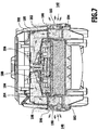
- the suction air can from the suction unit 26 via exhaust ports 29 ( FIG. 7 ) of the suction head 14 are discharged to the environment.
- the suction air flows through the filter 22, so that entrained solid particles deposit on the dirt collecting container 12 facing the dirty side 32 of the filter 22. It is therefore necessary to clean the filter 22 from time to time, since otherwise it forms an increasing flow resistance, whereby the suction effect of the vacuum cleaner 10 is impaired.
- a cleaning device which is designed as an external air valve device 33, with (at least) an external air valve 34 is disposed above the filter 22 in the suction head 14 (in FIG. 2 shown enlarged). It comprises a stationary in the suction head 14 arranged valve holder 36 which forms a valve seat for a movable valve body in the form of a valve disk 38.
- the valve disk 38 is acted upon by a closing spring 40 with a closing force in the direction of the valve holder 36.
- the closing spring 40 is clamped between a plate-like, a plurality of flow passages, fixedly arranged in the suction head 14 filter holder 42 and the valve plate 38.
- the filter holder 42 carries a resilient stop element in the form of a stop spring 44.
- This particular (preferably as well as the closing spring 40) has a linear characteristic. It is for example designed as a helical spring.
- the stop spring 44 is not under tension in the closed position of the valve disk 38. Only when the valve plate 38 lifts off the valve seat of the valve holder 36, the stopper spring 44 comes to rest on the underside of the valve disk 38 and is slightly compressed in a further movement of the valve disk 38. It thus exerts an increasing restoring force on the valve disk 38 and accelerates the movement of the valve disk 38 starting from its (in FIG. 2 shown) closed valve position via an open valve position back to the closed valve position. In the open valve position, the valve plate 38 takes a distance to the valve holder 36, which forms the valve seat.
- the valve holder 36 has a plurality of passage openings, not shown in the drawing, the mouth areas are closed by the valve plate 38 when it assumes its closed valve position.
- the suction head 14 has a lateral opening 46. Via the lateral opening 46, foreign air can flow into the passage openings of the valve holder 36. If the valve disk 36 has its open valve position spaced from the valve holder 36, the lateral opening 46 is in fluid communication with the suction line 24 via the passage openings of the valve holder 36 and the clean side 48 of the filter 22 facing away from the dirt collecting container 12 can act on it. If the valve disk 38 assumes its closed valve position, the flow connection between the lateral opening 46 and the suction line 24 is interrupted.
- the valve holder 36 carries an electromagnet 50.
- the electromagnet 50 In the circumferential direction of the electromagnet 50 is surrounded by an annular space 52, in which a molded upper side of the valve plate 38 guide sleeve 54 dips.
- the guide sleeve 54 receives a magnetizable element, for example in the form of an iron plate 56 which rests in the closed valve position of the valve disk 38 at a free end edge 58 of the electromagnet 50 and 50 forms a closed magnetic circuit in combination with the electromagnet.
- the electromagnet 50 is connected via a power supply line with an arranged in the suction head 14 (electronic) control device 62 in electrical connection. From the control device 62, the electromagnet 50 is applied during the normal suction operation of the vacuum cleaner 10 with a supply current. Due to the forming magnetic field of the valve plate 38 is reliably held in its closed position. The holding force of the electromagnet 50 is supported by the spring force of the closing spring 40.
- the magnetic holding force acting on the valve disk 38 is eliminated and the valve disk 38 becomes inactive due to the pressure difference acting on it, resulting from the external pressure of the external air present in the area of the valve holder 36 and the internal pressure within the suction line 24 results, lifted against the action of the closing spring 40 from the valve seat.
- External air can then flow abruptly through the passage openings of the valve holder 36 into the suction line 24 and the filter 22 is acted upon on its clean side 48 abruptly with external air. This leads to a mechanical vibration of the filter 22.
- the filter 22 in the counterflow direction that is, against the prevailing during normal suction operation flow direction 30, flows through external air. This results in an effective cleaning of the filter 22.
- the energy supply of the vacuum cleaner 10 is carried out in one embodiment by means of a rechargeable battery device.
- a rechargeable battery device This includes, for example, two rechargeable batteries.
- the battery device comprises, for example, one or more lithium-ion batteries. These are arranged laterally next to the suction unit 26 in a battery compartment 68 of the suction head 14. The battery compartment 68 is accessible via an outwardly pivotable flap 70 the user to replace the batteries.
- the electronic control device 62 is arranged above the suction unit 26 in the suction head 14 and is connected via supply lines to the batteries 64 in electrical connection.
- a user-actuated pushbutton 82 which is arranged on the upper side of the suction head 14, is connected to the control device 62. By pressing the button 82, the user can (manually) trigger a filter cleaning.
- the external air valve device 33 in the vacuum cleaner 10 is a noise source for popping noises.
- the sudden ("sudden") pressure change which leads to a reverse flow through the filter 22, leads to low-pitched pop noise.
- the relevant frequency range is usually well below 1000 Hz.
- the pressure drop is abrupt and has a duration of, for example, less than 0.05 s.
- the pressure change is in particular 50 mbar (5 kPa) or more.
- the sucker 10 is provided with a perforated plate resonator 84 (FIG. FIGS. 3 to 9 ; in FIG. 3 the perforated plate resonator is provided with the reference numeral 148 and in FIG. 6 with the reference numeral 206).
- the perforated plate resonator 84 is associated with the external air valve device 33, which forms the noise source, and connected with this sound effect.
- the perforated plate resonator 84 has ( FIG. 9 ) a chamber 85 with a chamber wall 86. This chamber wall 86 limits one Chamber chamber 88. The chamber chamber 88 is closed by a perforated plate 90.
- the perforated plate 90 is supported on the chamber wall 86 and is disposed thereon.
- the chamber wall 86 is connected to the perforated plate 90.
- the chamber wall 86 includes a top wall 92. This top wall 92 is spaced from and opposed to the perforated plate 90. Between the lid wall 92 and the perforated plate 90, the chamber space 88 is formed.
- the perforated plate 90 and the lid wall 92 are parallel to each other.
- the perforated plate 90 has a first side 94.
- the first side 94 faces the chamber space 88. It is also the top wall 92 facing.
- the perforated plate 90 further includes a second side 96.
- the second side 96 faces the first side 94. Between the first side 94 and the second side 96, the perforated plate 90 extends.
- the second side 96 of the perforated plate 90 is acoustically effective facing the noise source (in the vacuum cleaner 10 of the external air valve device 33). Sound waves may propagate from this noise source to the perforated plate 90 and enter the chamber space 88 through openings ("holes") in the perforated plate 90.
- the first side 94 and the second side 96 are parallel to each other.
- the perforated plate 90 is then formed correspondingly flat.
- the orifice plate resonator 84 includes a first transverse wall and a second transverse wall. These are spaced from each other.
- the first transverse wall and the second transverse wall are seated on the top wall 92 and protrude transversely beyond them.
- the apertured plate resonator 84 includes a first longitudinal wall 102 and a second longitudinal wall 104.
- the first longitudinal wall 102 and the second longitudinal wall 104 are spaced apart from each other and toward one another.
- the first longitudinal wall 102 and the second longitudinal wall 104 are formed, for example, parallel to each other.
- the first longitudinal wall 102 and the second longitudinal wall 104 are seated on the top wall 92 and protrude beyond them.
- the first longitudinal wall 102 and the second longitudinal wall 104 are transverse to the first transverse wall and the second transverse wall.
- the first transverse wall, the second transverse wall, the first longitudinal wall 102 and the second longitudinal wall 104 form a (lateral) wall 106, which sits on the cover wall 92 and closes the chamber space 98 laterally.
- the perforated plate 90 is arranged on this wall 106 and is supported, in particular, on end faces of this wall 106.
- first transverse wall 98, the second transverse wall 100, the first longitudinal wall 102, and the second longitudinal wall 104 are straight.
- the transverse walls are arranged, for example, at right angles to the longitudinal walls 102, 104.
- the chamber space 88 then has a hollow cuboid shape. Other embodiments are possible, as explained below.
- the chamber wall 96 is formed in particular of a reverberant material with a reflectance for sound greater than 94%, which accordingly has a low absorption capacity for sound.
- openings ("holes") 108 are arranged which are continuous between the first side 94 and the second side 96. At the first side 94, the openings open into the chamber space 88. At the second side 96, the openings 108 open into a channel, which is sound conducting. The channel is disposed between the noise source, that is, the external air valve device 33, and the orifice plate 90.
- a plurality of openings 108 is formed on the perforated plate 90. These are especially arranged regularly. They are arranged in particular on grid points of a two-dimensional grid. Elementary cells of this grid are, for example, squares, rectangles, trapezoids, triangles, etc.
- the openings 108 have a circular cross-section. As a result, they have a (hollow) cylindrical shape.
- An extension direction 112 of an opening 108 is oriented, for example, parallel to the transverse walls or longitudinal walls 102, 104.
- the extension direction 112 is oriented in particular perpendicular to the first side 94 and second side 96 of the perforated plate 90. It is also oriented in particular perpendicular to the top wall 92.
- a sound-absorbing material 114 as mineral fiber wool.
- the perforated plate resonator 84 is a perforated plate absorber having sound absorbing properties.
- the dimensioning of the perforated plate resonator 84 with respect to its geometric dimensions and the arrangement and dimension of the openings 108 determines the effective frequency range for the sound absorption.
- I is the thickness of the perforated plate 90 between the first side 94 and the second side 96 plus an orifice correction
- d is the height of the chamber space 88 between the first side 94 of the perforated plate 90 and an inner side of the lid wall 92
- c is the speed of sound.
- the opening area is the opening area (mouth area) of an opening 108.
- the total area is the total area of the perforated plate 90, which is exposed to the noise source, that is, which is acted upon by sound waves.
- the total area 10 corresponds to that area of the perforated plate 90 which assigns the channel.
- the perforated plate resonator 84 is designed such that the center frequency f 0 is approximately 675 Hz.
- a perforated plate resonator has the following characteristic variables: resonance frequency (center frequency), opening diameter, resonator height (height of the chamber space), thickness of the perforated plate and hole spacing.
- resonance frequency center frequency
- opening diameter opening diameter
- resonator height height of the chamber space
- thickness of the perforated plate and hole spacing.
- these variables are set so that there is sufficient noise reduction in the maximum level, for example, by more than 2.5 dB for the relevant frequencies.
- the suction head 14 is modified.
- a guide channel 120 is arranged. This guide channel 120 serves for the targeted inflow of air to the external air valve device 33 as a cleaning device.
- the guide channel 120 comprises a first region 122 with a first extension axis 124.
- the first region 122 is adjoined by a second region 126 with a second extension axis 128.
- the second region 126 is adjoined by a third region 130 with a third extension axis 132.
- the first extension axis 124 lies transversely and in particular perpendicular to the second extension axis 128.
- the third extension axis 132 lies transversely and in particular perpendicular to the second extension axis 128.
- the first extension axis 124 and the third extension axis 132 are in particular approximately parallel to one another.
- the filter 22 is located between the first region 122 and the third region 130. (A connection axis connecting the first region 122 and the third region 130 passes through the filter 22.)
- the second region 126 lies above the external air valve device 33.
- the guide channel 120 has a C-shape or staple shape and rests on the combination of filter device 21 and external air valve device 33, wherein the first region 122 and the third region 130 to a certain extent form legs, which bear laterally on this combination.
- the guide channel 120 has a first connection 134, via which it is coupled to the external air valve device 33. External air is provided to the external air valve device 33 via the first connection 134, which air can then flow into the suction line 24 through the through openings of the valve holder 36 and thereby abruptly impinges the filter 22 on its clean side 48 with external air.
- the first port 134 is formed in particular by one or more openings in correspondence with the through openings of the valve holder 36.
- the first connection 134 is seated on the second region 126. It sits in particular centrally on the second region 126 of the guide channel 120.
- the guide channel 120 also has a second connection 136.
- the second terminal 136 is disposed on the first region 122. He sits in particular at a height of the filter 22nd
- the second connection 136 is coupled to an exhaust air duct of the suction unit 26.
- the suction unit 26 provides clean air during a suction process. This is usually released to the environment.
- exhaust air of the suction unit 26 is completely discharged to the second port 136 and thus completely coupled into the guide channel 120 in the first region 122. Accordingly, an exhaust duct of the suction unit 26 is up to the first port 134 so formed fluid-tight, that exhaust air is completely coupled to the second port 136 in the guide channel 120.
- the guide channel 120 also has a third connection 138.
- This third terminal 138 is arranged on the third area 130.
- the third port 138 opens into the environment 140 of the suction device.
- a housing 142 of the suction head 14 has a grid structure 144 on the third connection 138.
- the guide channel 120 extends between the second port 136 and the third port 138. Exhaust air, which enters the guide channel 120 via the second port 136, exits into the environment 140 at the third port 138 when no filter cleaning operation is performed.
- the first port 134 Located midway between the second port 136 and the third port 138 is the first port 134.
- air from the environment 140 may also enter the guide channel 120 and flow to the first port 134.
- the second port 136 and the third port 138 are disposed on opposite housing side portions 146a, 146b. Between the second port 136 and the third port 138, the combination of filter device 21 and external air valve device 33 is positioned.
- the first connection 134 lies between the second connection 136 and the third connection 138.
- a perforated plate resonator 148 with a perforated plate 150 is arranged in the suction head 14 on the second region 126.
- the perforated plate 150 lies opposite the first connection 134.
- the guide channel 120 has a wall 152 in the second region 126.
- the perforated plate 150 forms a part 154 of this wall 152.
- the wall 152 has, outside the part 154, a region 156 which lies at least partially over the first region 122 and the third region 130, respectively.
- the corresponding region 156 is formed fluid-tight.
- the perforated plate 150 has a greater length in the second extension axis 128 in one embodiment than the first port 134 in this direction.
- the perforated plate resonator 148 with the perforated plate 150 is basically designed and operates as described above with reference to the perforated plate resonator 84.
- the perforated plate 150 is formed angled. It includes a first region 158, a second region 160 and a third region 162.
- the first region 158 and the third region 162 are respectively located opposite to one side of the second region 160. They are angled toward the second region 160 at an obtuse angle, for example in the order of 10 °.
- the first region 158 and the third region 162 continue into the regions 156, in particular in alignment.
- a fluid seal is arranged between the perforated plate 150 and the regions 156.
- the perforated plate 150 is configured in the described embodiment such that the guide channel 120 is formed on the second region 126 of the first terminal 134 opposite dome-shaped.
- the perforated plate resonator 148 has a chamber space 164 above the perforated plate 150 in the suction head 14.
- the perforated plate resonator 148 is fixed to a housing cover 166.
- the housing cover 166 may be opened to allow access to the external air valve device 33 and the filter device 21.
- the perforated plate resonator 148 is fixedly connected to the housing cover 166. With an opening of the housing cover 166, the perforated plate resonator is then moved together with the perforated plate 150, and the perforated plate resonator 148 then does not have to be removed again for access to the external air valve device 33 or the filter device 21.
- the suction device 10 in the modification according to the FIGS. 3 to 5 works as follows: Exhaust air of the suction unit 26 is completely coupled to the second port 136 in the guide channel 120.
- the exhaust air then flows through the first region 122 and the second region 126 of the guide channel 120.
- the exhaust air is provided to the first connection 134, so that during a cleaning process of the filter 22 corresponding external air is available.
- Exhaust air basically flows through the guide channel 120 and enters the environment 140 at the third connection 138.
- air from the environment 140 may also flow into the guide channel 120 and is thereby provided to the first port 134.
- Air in the guide channel 120 flows past the perforated plate resonator 148 in the second region 126.
- the first terminal 134 is opposite to the perforated plate 150 of the perforated plate resonator 148. This causes a reduction of the noise emission.
- the guide channel 120 is formed in the suction head 14. In particular, it is designed in such a way that no flow barriers are contained in it. He ensures a targeted air flow.
- a defined flow guidance for exhaust air is provided as an external air source.
- exhaust air of the suction unit 26 has a lower degree of contamination than air from the environment 140. It is achieved by an effective filter cleaning.
- the guide channel 120 has a first inflow region 168 between the second connection 136 and the first connection 134, via which external air can be made available to the first connection 134. It also has a second inflow region 170 between the third connection 138 and the first connection 134. For example, if the suction hose 18 is clogged and no exhaust air is provided, then still air in the second inflow region 170 can flow from the environment 140 and it is still provided at the first port 134 external air.
- the acoustic emission of the suction device 10 is effectively reduced by the perforated plate resonator 148.
- a guide channel 180 is provided.
- the guide channel 180 like the guide channel 120, comprises a first region 182, to which a second region 184 adjoins.
- the second region 184 is adjoined in turn by a third region 186.
- the first region 182 and the third region 186 are transverse and in particular perpendicular to the second region 184.
- a first connection 188 is arranged, via which, corresponding to the first connection 134 of the external air valve device 33, external air can be supplied directly.
- a second terminal 190 is arranged at the first region 182. Exhaust air from the suction unit 26 is coupled into the guide channel 180 via this second connection 190.
- the guide channel 180 has a third terminal 192, which is positioned on the third area 186. Via the third connection 192, according to the third connection 138, air which has flowed through the guide channel 180 can escape into the environment 140. Further, ambient air 140 at the third port 192 may enter the guide channel 180.
- the guide channel 180 has a fourth connection 194 on the third region 186.
- the fourth connection 194 is coupled to the exhaust air duct of the suction unit 26. At the fourth connection 194, exhaust air of the suction unit 26 enters the flow channel 180.
- the guide channel 180 has a fifth connection 196 in the first region 182.
- the fifth port 196 opens into the environment 140. Air may exit the guide channel 180 at the fifth port 196 into the environment 140 and ambient air may enter the guide channel 180.
- a grid structure corresponding to the grid structure 144 is arranged at the fifth terminal 196.
- the combination of filter device 21 and external air valve device 33 is positioned between the first region 182 and the third region 186 of the guide channel 180. It is also positioned between the second port 190 and the third port 192. It is also positioned between the fourth port 194 and the fifth port 196.
- the first terminal 188 is positioned midway between the combination of the second terminal 190 and the fifth terminal 196 on the one side and the combination of the third terminal 192 and the fourth terminal 194 on the other side.
- the second port 190 and the fifth port 196 are positioned close to each other on the same housing side area. Accordingly, the third port 192 and the fourth port 194 are positioned close to each other on the same housing side area.
- the guide channel 180 allows a first inflow region to the first port 188, which lies between the second port 190 and the first port 188. In the FIGS. 6 and 8th this first inflow region is designated 198.
- a second inflow region 200 is further formed on the guide channel 120. This second inflow region is formed between the third port 192 and the first port 188.
- exhaust air can flow from the suction unit 96 to the first port 188.
- a third inflow region 202 is present, which lies between the fourth connection 194 and the first connection 188.
- a fourth inflow region 204 is present, which lies between the fifth connection 196 and the first connection 188.
- Air from the environment 140 can flow to the first port 188 via the third inflow region 202 and the fourth inflow region 204. This is advantageous, for example, if not enough exhaust air (for example, due to a blockage of the suction hose 18) is available.
- the first inflow region 198 and the fourth inflow region 204 overlap.
- the second inflow region 200 and the third inflow region 202 overlap.
- the guide channel 180 is also formed symmetrically with respect to its terminals 190, 192, 194, 196. It is possible to achieve a symmetrical exhaust air inflow and outflow as well as symmetrical flow of air from the environment 140.
- the guide channel 180 is associated with a perforated plate resonator 206.
- a corresponding perforated plate is opposite the first port 188. It forms a wall of the guide channel 180.
- the guide channel 180 is integrated in the suction head 14.
- FIGS. 6 to 8 works basically the same as the embodiment according to the FIGS. 3 to 5 .
Landscapes
- Engineering & Computer Science (AREA)
- Mechanical Engineering (AREA)
- General Engineering & Computer Science (AREA)
- Filtering Of Dispersed Particles In Gases (AREA)
- Cleaning In General (AREA)
- Electric Suction Cleaners (AREA)
- Spinning Or Twisting Of Yarns (AREA)
Claims (15)
- Appareil d'aspiration, comportant un groupe d'aspiration (26), un récipient collecteur de saletés (12), un système de filtre (21), dans lequel le récipient collecteur de saletés (12) est en liaison fluidique avec le groupe d'aspiration (26) par l'intermédiaire du système de filtre (21), et un dispositif de nettoyage (33) pour le système de filtre (21), lequel comporte un dispositif de soupape d'air extérieur (33), caractérisé par au moins un canal de guidage (120 ; 180) pour l'air, lequel présente un premier raccord (134 ; 188), qui est en liaison fluidique avec le dispositif de nettoyage pour la fourniture d'air extérieur provenant du au moins un canal de guidage (120 ; 180), un deuxième raccord (136 ; 190) pour l'injection d'air vicié du groupe d'aspiration (26) dans le au moins un canal de guidage (120 ; 180), et présente un troisième raccord (138 ; 192), lequel est en liaison fluidique avec l'environnement (140) du groupe d'aspiration, dans lequel l'air provenant de l'environnement (140) peut affluer dans le au moins un canal de guidage (120 ; 180) par l'intermédiaire du troisième raccord (138 ; 192) .
- Appareil d'aspiration selon la revendication 1, caractérisé en ce que le troisième raccord (138 ; 192) est conçu de telle sorte que l'air évacué du groupe d'aspiration (26) peut sortir dans l'environnement (140) au niveau dudit raccord.
- Appareil d'aspiration selon la revendication 1 ou 2, caractérisé en ce que le au moins un canal de guidage (120 ; 180) s'étend entre le deuxième raccord (136 ; 190) et le troisième raccord (138 ; 192).
- Appareil d'aspiration selon l'une quelconque des revendications précédentes, caractérisé en ce que le premier raccord (134 ; 188) est positionné par rapport à un guidage d'écoulement et/ou de manière géométrique entre le deuxième raccord (136 ; 190) et le troisième raccord (138 ; 192) et en particulier au moins à peu près au centre entre le deuxième raccord (136 ; 190) et le troisième raccord (138 ; 192).
- Appareil d'aspiration selon l'une quelconque des revendications précédentes, caractérisé en ce que le au moins un canal de guidage (120 ; 180) présente une première zone (122 ; 182) pourvue d'un premier axe d'étendue (124), sur laquelle se situe le deuxième raccord (136 ; 190), une deuxième zone (126 ; 184) pourvue d'un deuxième axe d'étendue (128), sur laquelle se situe le premier raccord (134 ; 188), et une troisième zone (130 ; 186) pourvue d'un troisième axe d'étendue (132), sur laquelle se situe le troisième raccord (138 ; 192), dans lequel le premier axe d'étendue (124) et/ou le troisième axe d'étendue (132) sont orientés transversalement au deuxième axe d'étendue (128) et en particulier le premier raccord (134 ; 188) et le deuxième raccord (136 ; 190) se situent à des niveaux différents et/ou le premier raccord (134 ; 188) et le troisième raccord (138 ; 192) se situent à des niveaux différents, et en particulier en ce que la première zone (122 ; 182) et/ou la troisième zone (130 ; 186) sont agencées latéralement à côté du dispositif de nettoyage (33) ou du système de filtre (21).
- Appareil d'aspiration selon l'une quelconque des revendications précédentes, caractérisé en ce que le au moins un canal de guidage (120 ; 180) est agencé ou formé au moins en partie sur une zone de logement, laquelle recouvre le récipient collecteur de saletés (12) et/ou le système de filtre (21) et/ou le dispositif de nettoyage (33).
- Appareil d'aspiration selon l'une quelconque des revendications précédentes, caractérisé en ce que le au moins un canal de guidage (120) et le deuxième raccord (136) sont conçus de sorte que l'air vicié du groupe d'aspiration (26) pénètre entièrement dans le au moins un canal de guidage (120) et en particulier en ce que le au moins un canal de guidage (120) et le troisième raccord (138) sont conçus de sorte que l'air vicié du groupe d'aspiration (26), en dehors d'un processus de nettoyage du système de filtre (21), ne peut sortir dans l'environnement (140) qu'au niveau du troisième raccord (138), et en particulier caractérisé par une première zone d'admission (168) pour l'air menant au premier raccord (134), laquelle est formée entre le deuxième raccord (136) et le premier raccord (134), et une deuxième zone d'admission (170), laquelle est formée entre le troisième raccord (138) et le premier raccord (134).
- Appareil d'aspiration selon l'une quelconque des revendications 1 à 6, caractérisé en ce qu'un quatrième raccord (194) pour l'air vicié du groupe d'aspiration (26) est agencé sur le au moins un canal de guidage (180), et en particulier en ce qu'un cinquième raccord (196) au niveau de l'environnement (140) est agencé sur le au moins un canal de guidage (180), et en particulier en ce que le système de filtre (21) et/ou le dispositif de nettoyage (33) sont positionnés de manière géométrique entre le troisième raccord (192) et le cinquième raccord (196), et en particulier en ce que le troisième raccord (192) et le cinquième raccord (196) sont positionnés sur des faces opposées du logement, et en particulier en ce que le système de filtre (21) et/ou le dispositif de nettoyage (33) sont positionnés de manière géométrique entre le deuxième raccord (190) et le quatrième raccord (194), et en particulier en ce que le au moins un canal de guidage (180) est réalisé à symétrie spéculaire par rapport au troisième raccord (192) et au cinquième raccord (196) et/ou au deuxième raccord (190) et au quatrième raccord (194), dans lequel en particulier le premier raccord (188) se situe sur un plan de symétrie, et en particulier caractérisé par un guidage d'écoulement à symétrie spéculaire pour le guidage de l'air en direction du premier raccord (188), et en particulier en ce que le cinquième raccord (196) se situe sur une même zone latérale de logement que le deuxième raccord (190) et le quatrième raccord (194) se situe sur une même zone latérale de logement que le troisième raccord (192), et en particulier caractérisé par une première zone d'admission (198) pour l'air menant au premier raccord (188), laquelle est formée entre le deuxième raccord (190) et le premier raccord (188), une deuxième zone d'admission (200), laquelle est formée entre le troisième raccord (192) et le premier raccord (188), une troisième zone d'admission (202), laquelle est formée entre le quatrième raccord (194) et le premier raccord (188), et une quatrième zone d'admission (204), laquelle est formée entre le cinquième raccord (196) et le premier raccord (188), dans lequel en particulier la première zone d'admission (198) et la troisième zone d'admission (202) sont à symétrie spéculaire l'une par rapport à l'autre et en particulier la deuxième zone d'admission (200) et la quatrième zone d'admission (204) sont à symétrie spéculaire l'une par rapport à l'autre.
- Appareil d'aspiration selon l'une quelconque des revendications précédentes, caractérisé en ce qu'au moins un résonateur à plaque perforée (84 ; 148 ; 206) est associé au dispositif de nettoyage (33) de manière à absorber les sons, dans lequel le au moins un résonateur à plaque perforée (84 ; 148 ; 206) présente une chambre (85) pourvue d'un espace de chambre (88) et d'une paroi de chambre (86) et au moins une plaque perforée (90), laquelle recouvre l'espace de chambre (88), et en particulier en ce que le au moins un résonateur à plaque perforée (84 ; 148 ; 206), en ce qui concerne les dimensions géométriques et l'agencement et la réalisation des ouvertures (108) dans la au moins une plaque perforée (90), est dimensionné par rapport à une source de bruits (33) de telle sorte qu'une réduction du bruit au niveau maximal d'au moins 2,5 dB (150) est effectuée par le au moins un résonateur à plaque perforée, et en particulier en ce que le au moins un résonateur à plaque perforée (84 ; 148 ; 206) pourvu de la au moins une plaque perforée (90) est agencé à l'opposé du dispositif de nettoyage (33) et en particulier du premier raccord (134 ; 188), et en particulier en ce que la au moins une plaque perforée (90) est agencée sur la paroi de chambre (86) et en particulier une paroi (106) de la paroi de chambre (86) s'appuie sur la plaque perforée (90) .
- Appareil d'aspiration selon la revendication 9, caractérisé en ce que la au moins une plaque perforée (90) du au moins un résonateur à plaque perforée (84 ; 148 ; 206) présente une première face (94), laquelle est tournée vers l'espace de chambre (88), et une deuxième face (96), laquelle est opposée à la première face (94), dans lequel une pluralité d'ouvertures (108) sont ménagées dans la au moins une plaque perforée (90), lesquelles sont continues entre la première face (94) et la deuxième face (96), et en particulier en ce que la première face (94) et/ou la deuxième face (96) sont plates, et en particulier en ce que la première face (94) et la deuxième face (96) sont parallèles l'une à l'autre, et en particulier en ce que les ouvertures (108), au niveau de la première face (94), débouchent dans l'espace de chambre (88) et, au niveau de la deuxième face (96), sont tournées vers le premier raccord, et en particulier en ce que les ouvertures (108) débouchent au niveau de la deuxième face (96) dans le au moins un canal de guidage (120 ; 180) et en particulier débouchent dans une deuxième zone (126 ; 184) du au moins un canal de guidage (120 ; 180) .
- Appareil d'aspiration selon la revendication 9 ou 10, caractérisé en ce que la paroi de chambre (86) présente une paroi de couvercle (92), laquelle est opposée à la au moins une plaque perforée (90), et une paroi (106), laquelle se situe entre la paroi de couvercle (92) et la au moins une plaque perforée (90), et en particulier en ce que la au moins une plaque perforée (90) et la paroi de couvercle (92) sont orientées parallèlement et en particulier en ce que l'espace de chambre (88) présente une forme parallélépipédique creuse.
- Appareil d'aspiration selon l'une quelconque des revendications 9 à 11, caractérisé en ce que la au moins une plaque perforée (150) n'est pas plate et présente en particulier une première zone (182), une deuxième zone (184) et une troisième zone (186), dans lequel la première zone (182) et la troisième zone (186) sont agencées à l'opposé sur la deuxième zone (184) et se situent de manière angulaire par rapport à la deuxième zone (184).
- Appareil d'aspiration selon l'une quelconque des revendications 9 à 12, caractérisé en ce que la paroi de chambre (86) présente une première paroi transversale (98), une deuxième paroi transversale (100), une première paroi longitudinale (102), une deuxième paroi longitudinale (104) et une paroi de couvercle (92), dans lequel la première paroi transversale (98) et la deuxième paroi transversale (100) sont espacées et dirigées l'une vers l'autre, la première paroi longitudinale (102) et la deuxième paroi longitudinale (104) sont espacées l'une de l'autre et dirigées l'une vers l'autre, la première paroi transversale (98) et la première paroi longitudinale (102) sont orientées transversalement l'une à l'autre, et la paroi de couvercle (92) est orientée transversalement à la première paroi transversale (98), à la deuxième paroi transversale (100), à la première paroi longitudinale (102) et à la deuxième paroi longitudinale (104), et en particulier en ce que la première paroi transversale (98) et la deuxième paroi transversale (100) sont orientées parallèlement et/ou la première paroi longitudinale (102) et la deuxième paroi longitudinale (104) sont orientées parallèlement.
- Appareil d'aspiration selon l'une quelconque des revendications 9 à 13, caractérisé en ce que la paroi de chambre (86) est fabriquée au moins en partie à partir d'un matériau réverbérant, et en particulier en ce que le au moins un résonateur à plaque perforée (148 ; 206) et en particulier la au moins une plaque perforée (150) forme une paroi du au moins un canal de guidage (120 ; 180), et en particulier en ce que le au moins un résonateur à plaque perforée (148 ; 206) est agencé sur un couvercle de logement (166) et en particulier fixé à celui-ci.
- Procédé pour faire fonctionner un appareil d'aspiration, dans lequel l'appareil d'aspiration comprend un groupe d'aspiration (26), un récipient collecteur de saletés (12), un système de filtre (21), dans lequel le récipient collecteur de saletés (12) est en liaison fluidique avec le groupe d'aspiration (26) par l'intermédiaire du système de filtre (21), et un dispositif de nettoyage (33) pour le système de filtre (21), lequel comprend un dispositif de soupape d'air extérieur (33), selon lequel l'air vicié du groupe d'aspiration (26) est amené de manière définie au dispositif de nettoyage par l'intermédiaire d'au moins un canal de guidage (120 ; 180), dans lequel l'air vicié est rejeté du au moins un canal de guidage (120 ; 180) dans l'environnement (140) par l'intermédiaire d'au moins un raccord (138 ; 192, 196), et dans lequel le au moins un raccord (138 ; 192, 196) est également réalisé sous la forme de raccord d'entrée pour l'air provenant de l'environnement (140), de sorte que l'air provenant de l'environnement (140) peut être amené au dispositif de nettoyage (33) par le biais du au moins un canal de guidage (120 ; 180).
Priority Applications (1)
| Application Number | Priority Date | Filing Date | Title |
|---|---|---|---|
| PL15706470T PL3244785T3 (pl) | 2015-01-13 | 2015-02-24 | Urządzenie ssące i sposób eksploatacji urządzenia ssącego |
Applications Claiming Priority (3)
| Application Number | Priority Date | Filing Date | Title |
|---|---|---|---|
| PCT/EP2015/050500 WO2016112959A1 (fr) | 2015-01-13 | 2015-01-13 | Aspirateur |
| DE102015100426.7A DE102015100426A1 (de) | 2015-01-13 | 2015-01-13 | Reinigungsgerät und Verfahren zur Lärmminderung bei einem Reinigungsgerät |
| PCT/EP2015/053840 WO2016112996A1 (fr) | 2015-01-13 | 2015-02-24 | Appareil d'aspiration et procédé permettant de faire fonctionner un appareil d'aspiration |
Publications (2)
| Publication Number | Publication Date |
|---|---|
| EP3244785A1 EP3244785A1 (fr) | 2017-11-22 |
| EP3244785B1 true EP3244785B1 (fr) | 2019-04-10 |
Family
ID=52589396
Family Applications (1)
| Application Number | Title | Priority Date | Filing Date |
|---|---|---|---|
| EP15706470.0A Active EP3244785B1 (fr) | 2015-01-13 | 2015-02-24 | Appareil d'aspiration et procédé permettant de faire fonctionner un appareil d'aspiration |
Country Status (9)
| Country | Link |
|---|---|
| US (1) | US10376113B2 (fr) |
| EP (1) | EP3244785B1 (fr) |
| CN (1) | CN107249414B (fr) |
| AU (1) | AU2015377942B2 (fr) |
| DK (1) | DK3244785T3 (fr) |
| PL (1) | PL3244785T3 (fr) |
| RU (1) | RU2663400C1 (fr) |
| TR (1) | TR201906687T4 (fr) |
| WO (1) | WO2016112996A1 (fr) |
Families Citing this family (9)
| Publication number | Priority date | Publication date | Assignee | Title |
|---|---|---|---|---|
| US11297990B2 (en) * | 2016-12-01 | 2022-04-12 | Skybest Electric Appliance Co., Ltd. | Dust collector and self-cleaning method for filter thereof |
| EP3586710B1 (fr) * | 2017-02-27 | 2022-06-15 | Skybest Electric Appliance (Suzhou) Co., Ltd. | Aspirateur à fonction d'auto-nettoyage et procédé d'auto-nettoyage associé |
| SE541827C2 (en) * | 2017-05-02 | 2019-12-27 | Husqvarna Ab | Valve, use of such valve, separator comprising such valve and method of operating a separator |
| EP3651629B1 (fr) | 2017-07-12 | 2021-09-08 | Alfred Kärcher SE & Co. KG | Aspirateur avec au moins deux filtres et méthode d'utiliser l'aspirateur |
| US11122945B2 (en) * | 2017-12-04 | 2021-09-21 | Transform Sr Brands Llc | Two-in-one upright vacuum |
| DE112018007149A5 (de) * | 2018-02-22 | 2020-11-26 | Alfred Kärcher SE & Co. KG | Sauggerät mit Filterabreinigungseinrichtung und einer Mehrzahl von Verschlusselementen |
| KR102071392B1 (ko) * | 2018-05-31 | 2020-03-02 | 엘지전자 주식회사 | 청소기 |
| DE102019100489A1 (de) | 2019-01-10 | 2020-07-16 | Alfred Kärcher SE & Co. KG | Filtervorrichtung für eine Saugmaschine und Saugmaschine |
| GB2588228B (en) * | 2019-10-18 | 2024-01-03 | Vectorplex Group Ltd | A portable extraction system and method |
Family Cites Families (23)
| Publication number | Priority date | Publication date | Assignee | Title |
|---|---|---|---|---|
| JPH02307418A (ja) | 1989-05-23 | 1990-12-20 | Matsushita Electric Ind Co Ltd | 真空掃除機用吸込みパイプ |
| DE4315759C1 (de) | 1993-05-11 | 1994-05-05 | Fraunhofer Ges Forschung | Schallabsorbierendes Glas- oder transparentes Kunstglasbauteil |
| DE19517197A1 (de) | 1995-05-11 | 1996-11-14 | Manfred Butsch | Selbstreinigender Staubsauger |
| DE19747318C1 (de) | 1997-10-27 | 1999-05-27 | Kaercher Gmbh & Co Alfred | Reinigungsgerät |
| DE60013087T2 (de) | 2000-01-27 | 2005-07-14 | New Ermes Europe S.P.A., Albizzate | Turbobürste zum Reinigen von Oberflächen |
| EP1172059A1 (fr) | 2000-07-14 | 2002-01-16 | Nilfisk Advance A/S | Aspirateur de poussières avec des moyens de réduction de bruit |
| CN100372489C (zh) | 2003-06-23 | 2008-03-05 | 乐金电子(天津)电器有限公司 | 真空吸尘器 |
| DE102005017702A1 (de) * | 2005-04-11 | 2006-10-12 | Alfred Kärcher Gmbh & Co. Kg | Verfahren zum Abreinigen der Filter eines Staubsaugers sowie Staubsauger zur Durchführung des Verfahrens |
| DE102005017568B4 (de) * | 2005-04-11 | 2024-04-25 | Alfred Kärcher SE & Co. KG | Saugreinigungsgerät |
| JP2007111308A (ja) | 2005-10-21 | 2007-05-10 | Matsushita Electric Ind Co Ltd | 消音装置およびそれを用いた電気掃除機 |
| CN100423678C (zh) | 2005-11-10 | 2008-10-08 | 苏州金莱克家用电器有限公司 | 吸尘器消音装置 |
| PL2046184T3 (pl) * | 2006-07-29 | 2014-06-30 | Kaercher Gmbh & Co Kg Alfred | Sposób czyszczenia filtrów odkurzacza oraz odkurzacz do realizacji tego sposobu |
| PL2049001T3 (pl) * | 2006-07-29 | 2014-04-30 | Kaercher Gmbh & Co Kg Alfred | Odkurzacz z urządzeniem do samoczynnego oczyszczania filtra |
| PL2046182T3 (pl) * | 2006-07-29 | 2014-10-31 | Kaercher Gmbh & Co Kg Alfred | Odkurzacz z urządzeniem do samooczyszczania filtru |
| WO2008014796A1 (fr) * | 2006-07-29 | 2008-02-07 | Alfred Kärcher Gmbh & Co. Kg | Aspirateur |
| ATE479377T1 (de) * | 2006-07-29 | 2010-09-15 | Kaercher Gmbh & Co Kg Alfred | Verfahren zum abreinigen der filter eines staubsaugers sowie staubsauger zur durchführung des verfahrens |
| JP2009100840A (ja) | 2007-10-22 | 2009-05-14 | Panasonic Corp | 電動送風機およびそれを用いた電気掃除機 |
| RU2492909C2 (ru) * | 2009-04-22 | 2013-09-20 | Альфред Кэрхер Гмбх & Ко. Кг | Способ очистки двух фильтров всасывающего аппарата для очистных целей, а также всасывающий аппарат для осуществления способа |
| CN102481079B (zh) * | 2009-07-07 | 2014-09-10 | 阿尔弗雷德·凯驰两合公司 | 用于清洁目的的抽吸器 |
| DE102010029524A1 (de) * | 2010-05-31 | 2011-12-01 | Alfred Kärcher Gmbh & Co. Kg | Staubsauger |
| US8893851B2 (en) | 2010-12-21 | 2014-11-25 | Yoshiharu Kitamura | Soundproofing plate which does not obstruct airflow |
| RU2532017C1 (ru) * | 2011-02-11 | 2014-10-27 | Альфред Кэрхер Гмбх Унд Ко. Кг | Способ очистки фильтра пылесоса, а также пылесос для осуществления способа |
| KR101964644B1 (ko) | 2012-05-10 | 2019-04-02 | 엘지전자 주식회사 | 소음저감부가 구비된 가전기기 |
-
2015
- 2015-02-24 WO PCT/EP2015/053840 patent/WO2016112996A1/fr active Application Filing
- 2015-02-24 RU RU2017128744A patent/RU2663400C1/ru active
- 2015-02-24 PL PL15706470T patent/PL3244785T3/pl unknown
- 2015-02-24 TR TR2019/06687T patent/TR201906687T4/tr unknown
- 2015-02-24 CN CN201580073313.2A patent/CN107249414B/zh active Active
- 2015-02-24 EP EP15706470.0A patent/EP3244785B1/fr active Active
- 2015-02-24 AU AU2015377942A patent/AU2015377942B2/en active Active
- 2015-02-24 DK DK15706470.0T patent/DK3244785T3/da active
-
2017
- 2017-07-11 US US15/646,783 patent/US10376113B2/en active Active
Non-Patent Citations (1)
| Title |
|---|
| None * |
Also Published As
| Publication number | Publication date |
|---|---|
| PL3244785T3 (pl) | 2019-09-30 |
| CN107249414B (zh) | 2020-07-17 |
| US10376113B2 (en) | 2019-08-13 |
| TR201906687T4 (tr) | 2019-05-21 |
| RU2663400C1 (ru) | 2018-08-03 |
| AU2015377942A1 (en) | 2017-08-31 |
| CN107249414A (zh) | 2017-10-13 |
| EP3244785A1 (fr) | 2017-11-22 |
| DK3244785T3 (da) | 2019-07-01 |
| US20170340179A1 (en) | 2017-11-30 |
| AU2015377942B2 (en) | 2020-07-02 |
| WO2016112996A1 (fr) | 2016-07-21 |
Similar Documents
| Publication | Publication Date | Title |
|---|---|---|
| EP3244785B1 (fr) | Appareil d'aspiration et procédé permettant de faire fonctionner un appareil d'aspiration | |
| EP3244784B1 (fr) | Aspirateur | |
| EP2052660B1 (fr) | Appareil d'aspiration | |
| EP1868478B1 (fr) | Appareil de nettoyage par aspiration | |
| DE102014204238A1 (de) | Luftreinigungseinrichtung | |
| EP0955003B1 (fr) | Aspirateur à des fins de nettoyage | |
| DE29823411U1 (de) | Sauggerät für Reinigungszwecke | |
| DE102016118807A1 (de) | Rückspülbarer Luftfilter und Staubsauger mit einem rückspülbaren Luftfilter | |
| DE102010001678A1 (de) | Kehrmaschine | |
| WO2022079069A1 (fr) | Dispositif de nettoyage et utilisation | |
| WO2016113195A1 (fr) | Appareil de nettoyage et procédé de réduction du bruit sur un appareil de nettoyage | |
| EP3651629B1 (fr) | Aspirateur avec au moins deux filtres et méthode d'utiliser l'aspirateur | |
| DE10104129A1 (de) | Hörgerät und Filtereinheit für ein solches | |
| DE202019100637U1 (de) | Haushaltsreinigungsgerät | |
| EP4103886A1 (fr) | Dispositif d'extraction de fumées, système d'installation et kit d'assemblage pour un dispositif d'extraction de fumées | |
| DE202010006419U1 (de) | Breitbandig dämpfende Vorrichtung zur Schalldämpfung bei Industrieeinrichtungen, Großanlagen oder Maschinen | |
| DE102019216294A1 (de) | Pilzventil für ein Luftfilter und ein Luftfilter | |
| EP3048942A1 (fr) | Appareil de nettoyage | |
| DE9113807U1 (de) | Luftfilter für eine Brennkraftmaschine | |
| EP2510850B1 (fr) | Agencement silencieux de filtre d'air évacué | |
| EP3764861B1 (fr) | Aspirateur | |
| DE112021000958T5 (de) | Kompakte luftfilterbaugruppe mit geräuschreduktionsvorrichtung | |
| DE3015383A1 (de) | Schalldaempfer | |
| DE3432485A1 (de) | Schalldaempferfilter | |
| DE9113963U1 (de) | Vorrichtung insbesondere zur Schalldämpfung der von einem Verdichter angesaugten Luft |
Legal Events
| Date | Code | Title | Description |
|---|---|---|---|
| STAA | Information on the status of an ep patent application or granted ep patent |
Free format text: STATUS: THE INTERNATIONAL PUBLICATION HAS BEEN MADE |
|
| PUAI | Public reference made under article 153(3) epc to a published international application that has entered the european phase |
Free format text: ORIGINAL CODE: 0009012 |
|
| STAA | Information on the status of an ep patent application or granted ep patent |
Free format text: STATUS: REQUEST FOR EXAMINATION WAS MADE |
|
| 17P | Request for examination filed |
Effective date: 20170707 |
|
| AK | Designated contracting states |
Kind code of ref document: A1 Designated state(s): AL AT BE BG CH CY CZ DE DK EE ES FI FR GB GR HR HU IE IS IT LI LT LU LV MC MK MT NL NO PL PT RO RS SE SI SK SM TR |
|
| AX | Request for extension of the european patent |
Extension state: BA ME |
|
| DAX | Request for extension of the european patent (deleted) | ||
| RAP1 | Party data changed (applicant data changed or rights of an application transferred) |
Owner name: ALFRED KAERCHER SE & CO. KG |
|
| GRAP | Despatch of communication of intention to grant a patent |
Free format text: ORIGINAL CODE: EPIDOSNIGR1 |
|
| STAA | Information on the status of an ep patent application or granted ep patent |
Free format text: STATUS: GRANT OF PATENT IS INTENDED |
|
| INTG | Intention to grant announced |
Effective date: 20180917 |
|
| GRAS | Grant fee paid |
Free format text: ORIGINAL CODE: EPIDOSNIGR3 |
|
| GRAA | (expected) grant |
Free format text: ORIGINAL CODE: 0009210 |
|
| STAA | Information on the status of an ep patent application or granted ep patent |
Free format text: STATUS: THE PATENT HAS BEEN GRANTED |
|
| AK | Designated contracting states |
Kind code of ref document: B1 Designated state(s): AL AT BE BG CH CY CZ DE DK EE ES FI FR GB GR HR HU IE IS IT LI LT LU LV MC MK MT NL NO PL PT RO RS SE SI SK SM TR |
|
| REG | Reference to a national code |
Ref country code: GB Ref legal event code: FG4D Free format text: NOT ENGLISH |
|
| REG | Reference to a national code |
Ref country code: CH Ref legal event code: EP Ref country code: AT Ref legal event code: REF Ref document number: 1117544 Country of ref document: AT Kind code of ref document: T Effective date: 20190415 |
|
| REG | Reference to a national code |
Ref country code: DE Ref legal event code: R096 Ref document number: 502015008633 Country of ref document: DE |
|
| REG | Reference to a national code |
Ref country code: IE Ref legal event code: FG4D Free format text: LANGUAGE OF EP DOCUMENT: GERMAN |
|
| REG | Reference to a national code |
Ref country code: DK Ref legal event code: T3 Effective date: 20190624 |
|
| REG | Reference to a national code |
Ref country code: NL Ref legal event code: MP Effective date: 20190410 |
|
| REG | Reference to a national code |
Ref country code: LT Ref legal event code: MG4D |
|
| REG | Reference to a national code |
Ref country code: NO Ref legal event code: T2 Effective date: 20190410 |
|
| PG25 | Lapsed in a contracting state [announced via postgrant information from national office to epo] |
Ref country code: NL Free format text: LAPSE BECAUSE OF FAILURE TO SUBMIT A TRANSLATION OF THE DESCRIPTION OR TO PAY THE FEE WITHIN THE PRESCRIBED TIME-LIMIT Effective date: 20190410 |
|
| PG25 | Lapsed in a contracting state [announced via postgrant information from national office to epo] |
Ref country code: FI Free format text: LAPSE BECAUSE OF FAILURE TO SUBMIT A TRANSLATION OF THE DESCRIPTION OR TO PAY THE FEE WITHIN THE PRESCRIBED TIME-LIMIT Effective date: 20190410 Ref country code: LT Free format text: LAPSE BECAUSE OF FAILURE TO SUBMIT A TRANSLATION OF THE DESCRIPTION OR TO PAY THE FEE WITHIN THE PRESCRIBED TIME-LIMIT Effective date: 20190410 Ref country code: ES Free format text: LAPSE BECAUSE OF FAILURE TO SUBMIT A TRANSLATION OF THE DESCRIPTION OR TO PAY THE FEE WITHIN THE PRESCRIBED TIME-LIMIT Effective date: 20190410 Ref country code: AL Free format text: LAPSE BECAUSE OF FAILURE TO SUBMIT A TRANSLATION OF THE DESCRIPTION OR TO PAY THE FEE WITHIN THE PRESCRIBED TIME-LIMIT Effective date: 20190410 Ref country code: HR Free format text: LAPSE BECAUSE OF FAILURE TO SUBMIT A TRANSLATION OF THE DESCRIPTION OR TO PAY THE FEE WITHIN THE PRESCRIBED TIME-LIMIT Effective date: 20190410 Ref country code: SE Free format text: LAPSE BECAUSE OF FAILURE TO SUBMIT A TRANSLATION OF THE DESCRIPTION OR TO PAY THE FEE WITHIN THE PRESCRIBED TIME-LIMIT Effective date: 20190410 Ref country code: PT Free format text: LAPSE BECAUSE OF FAILURE TO SUBMIT A TRANSLATION OF THE DESCRIPTION OR TO PAY THE FEE WITHIN THE PRESCRIBED TIME-LIMIT Effective date: 20190910 |
|
| PG25 | Lapsed in a contracting state [announced via postgrant information from national office to epo] |
Ref country code: GR Free format text: LAPSE BECAUSE OF FAILURE TO SUBMIT A TRANSLATION OF THE DESCRIPTION OR TO PAY THE FEE WITHIN THE PRESCRIBED TIME-LIMIT Effective date: 20190711 Ref country code: LV Free format text: LAPSE BECAUSE OF FAILURE TO SUBMIT A TRANSLATION OF THE DESCRIPTION OR TO PAY THE FEE WITHIN THE PRESCRIBED TIME-LIMIT Effective date: 20190410 Ref country code: BG Free format text: LAPSE BECAUSE OF FAILURE TO SUBMIT A TRANSLATION OF THE DESCRIPTION OR TO PAY THE FEE WITHIN THE PRESCRIBED TIME-LIMIT Effective date: 20190710 Ref country code: RS Free format text: LAPSE BECAUSE OF FAILURE TO SUBMIT A TRANSLATION OF THE DESCRIPTION OR TO PAY THE FEE WITHIN THE PRESCRIBED TIME-LIMIT Effective date: 20190410 |
|
| PG25 | Lapsed in a contracting state [announced via postgrant information from national office to epo] |
Ref country code: IS Free format text: LAPSE BECAUSE OF FAILURE TO SUBMIT A TRANSLATION OF THE DESCRIPTION OR TO PAY THE FEE WITHIN THE PRESCRIBED TIME-LIMIT Effective date: 20190810 |
|
| REG | Reference to a national code |
Ref country code: DE Ref legal event code: R097 Ref document number: 502015008633 Country of ref document: DE |
|
| PG25 | Lapsed in a contracting state [announced via postgrant information from national office to epo] |
Ref country code: SK Free format text: LAPSE BECAUSE OF FAILURE TO SUBMIT A TRANSLATION OF THE DESCRIPTION OR TO PAY THE FEE WITHIN THE PRESCRIBED TIME-LIMIT Effective date: 20190410 Ref country code: RO Free format text: LAPSE BECAUSE OF FAILURE TO SUBMIT A TRANSLATION OF THE DESCRIPTION OR TO PAY THE FEE WITHIN THE PRESCRIBED TIME-LIMIT Effective date: 20190410 Ref country code: CZ Free format text: LAPSE BECAUSE OF FAILURE TO SUBMIT A TRANSLATION OF THE DESCRIPTION OR TO PAY THE FEE WITHIN THE PRESCRIBED TIME-LIMIT Effective date: 20190410 Ref country code: EE Free format text: LAPSE BECAUSE OF FAILURE TO SUBMIT A TRANSLATION OF THE DESCRIPTION OR TO PAY THE FEE WITHIN THE PRESCRIBED TIME-LIMIT Effective date: 20190410 |
|
| PLBE | No opposition filed within time limit |
Free format text: ORIGINAL CODE: 0009261 |
|
| STAA | Information on the status of an ep patent application or granted ep patent |
Free format text: STATUS: NO OPPOSITION FILED WITHIN TIME LIMIT |
|
| PG25 | Lapsed in a contracting state [announced via postgrant information from national office to epo] |
Ref country code: SM Free format text: LAPSE BECAUSE OF FAILURE TO SUBMIT A TRANSLATION OF THE DESCRIPTION OR TO PAY THE FEE WITHIN THE PRESCRIBED TIME-LIMIT Effective date: 20190410 |
|
| 26N | No opposition filed |
Effective date: 20200113 |
|
| PG25 | Lapsed in a contracting state [announced via postgrant information from national office to epo] |
Ref country code: SI Free format text: LAPSE BECAUSE OF FAILURE TO SUBMIT A TRANSLATION OF THE DESCRIPTION OR TO PAY THE FEE WITHIN THE PRESCRIBED TIME-LIMIT Effective date: 20190410 |
|
| REG | Reference to a national code |
Ref country code: CH Ref legal event code: PL |
|
| REG | Reference to a national code |
Ref country code: BE Ref legal event code: MM Effective date: 20200229 |
|
| PG25 | Lapsed in a contracting state [announced via postgrant information from national office to epo] |
Ref country code: LU Free format text: LAPSE BECAUSE OF NON-PAYMENT OF DUE FEES Effective date: 20200224 Ref country code: MC Free format text: LAPSE BECAUSE OF FAILURE TO SUBMIT A TRANSLATION OF THE DESCRIPTION OR TO PAY THE FEE WITHIN THE PRESCRIBED TIME-LIMIT Effective date: 20190410 |
|
| PG25 | Lapsed in a contracting state [announced via postgrant information from national office to epo] |
Ref country code: LI Free format text: LAPSE BECAUSE OF NON-PAYMENT OF DUE FEES Effective date: 20200229 Ref country code: CH Free format text: LAPSE BECAUSE OF NON-PAYMENT OF DUE FEES Effective date: 20200229 |
|
| PG25 | Lapsed in a contracting state [announced via postgrant information from national office to epo] |
Ref country code: IE Free format text: LAPSE BECAUSE OF NON-PAYMENT OF DUE FEES Effective date: 20200224 |
|
| PG25 | Lapsed in a contracting state [announced via postgrant information from national office to epo] |
Ref country code: BE Free format text: LAPSE BECAUSE OF NON-PAYMENT OF DUE FEES Effective date: 20200229 |
|
| REG | Reference to a national code |
Ref country code: AT Ref legal event code: MM01 Ref document number: 1117544 Country of ref document: AT Kind code of ref document: T Effective date: 20200224 |
|
| PG25 | Lapsed in a contracting state [announced via postgrant information from national office to epo] |
Ref country code: AT Free format text: LAPSE BECAUSE OF NON-PAYMENT OF DUE FEES Effective date: 20200224 |
|
| PG25 | Lapsed in a contracting state [announced via postgrant information from national office to epo] |
Ref country code: MT Free format text: LAPSE BECAUSE OF FAILURE TO SUBMIT A TRANSLATION OF THE DESCRIPTION OR TO PAY THE FEE WITHIN THE PRESCRIBED TIME-LIMIT Effective date: 20190410 Ref country code: CY Free format text: LAPSE BECAUSE OF FAILURE TO SUBMIT A TRANSLATION OF THE DESCRIPTION OR TO PAY THE FEE WITHIN THE PRESCRIBED TIME-LIMIT Effective date: 20190410 |
|
| PG25 | Lapsed in a contracting state [announced via postgrant information from national office to epo] |
Ref country code: MK Free format text: LAPSE BECAUSE OF FAILURE TO SUBMIT A TRANSLATION OF THE DESCRIPTION OR TO PAY THE FEE WITHIN THE PRESCRIBED TIME-LIMIT Effective date: 20190410 |
|
| P01 | Opt-out of the competence of the unified patent court (upc) registered |
Effective date: 20230523 |
|
| PGFP | Annual fee paid to national office [announced via postgrant information from national office to epo] |
Ref country code: PL Payment date: 20231212 Year of fee payment: 10 |
|
| PGFP | Annual fee paid to national office [announced via postgrant information from national office to epo] |
Ref country code: DE Payment date: 20240226 Year of fee payment: 10 Ref country code: GB Payment date: 20240108 Year of fee payment: 10 |
|
| PGFP | Annual fee paid to national office [announced via postgrant information from national office to epo] |
Ref country code: TR Payment date: 20240210 Year of fee payment: 10 Ref country code: NO Payment date: 20240208 Year of fee payment: 10 Ref country code: IT Payment date: 20240111 Year of fee payment: 10 Ref country code: FR Payment date: 20240103 Year of fee payment: 10 Ref country code: DK Payment date: 20240214 Year of fee payment: 10 |