EP3243779A1 - Förderband für druckbogen - Google Patents
Förderband für druckbogen Download PDFInfo
- Publication number
- EP3243779A1 EP3243779A1 EP17165699.4A EP17165699A EP3243779A1 EP 3243779 A1 EP3243779 A1 EP 3243779A1 EP 17165699 A EP17165699 A EP 17165699A EP 3243779 A1 EP3243779 A1 EP 3243779A1
- Authority
- EP
- European Patent Office
- Prior art keywords
- conveyor belt
- projections
- belt according
- vacuum
- printed sheets
- Prior art date
- Legal status (The legal status is an assumption and is not a legal conclusion. Google has not performed a legal analysis and makes no representation as to the accuracy of the status listed.)
- Granted
Links
Images


Classifications
-
- B—PERFORMING OPERATIONS; TRANSPORTING
- B41—PRINTING; LINING MACHINES; TYPEWRITERS; STAMPS
- B41J—TYPEWRITERS; SELECTIVE PRINTING MECHANISMS, i.e. MECHANISMS PRINTING OTHERWISE THAN FROM A FORME; CORRECTION OF TYPOGRAPHICAL ERRORS
- B41J13/00—Devices or arrangements of selective printing mechanisms, e.g. ink-jet printers or thermal printers, specially adapted for supporting or handling copy material in short lengths, e.g. sheets
- B41J13/08—Conveyor bands or like feeding devices
-
- B—PERFORMING OPERATIONS; TRANSPORTING
- B65—CONVEYING; PACKING; STORING; HANDLING THIN OR FILAMENTARY MATERIAL
- B65H—HANDLING THIN OR FILAMENTARY MATERIAL, e.g. SHEETS, WEBS, CABLES
- B65H29/00—Delivering or advancing articles from machines; Advancing articles to or into piles
- B65H29/24—Delivering or advancing articles from machines; Advancing articles to or into piles by air blast or suction apparatus
- B65H29/241—Suction devices
- B65H29/242—Suction bands or belts
-
- B—PERFORMING OPERATIONS; TRANSPORTING
- B41—PRINTING; LINING MACHINES; TYPEWRITERS; STAMPS
- B41J—TYPEWRITERS; SELECTIVE PRINTING MECHANISMS, i.e. MECHANISMS PRINTING OTHERWISE THAN FROM A FORME; CORRECTION OF TYPOGRAPHICAL ERRORS
- B41J11/00—Devices or arrangements of selective printing mechanisms, e.g. ink-jet printers or thermal printers, for supporting or handling copy material in sheet or web form
- B41J11/007—Conveyor belts or like feeding devices
-
- B—PERFORMING OPERATIONS; TRANSPORTING
- B41—PRINTING; LINING MACHINES; TYPEWRITERS; STAMPS
- B41J—TYPEWRITERS; SELECTIVE PRINTING MECHANISMS, i.e. MECHANISMS PRINTING OTHERWISE THAN FROM A FORME; CORRECTION OF TYPOGRAPHICAL ERRORS
- B41J11/00—Devices or arrangements of selective printing mechanisms, e.g. ink-jet printers or thermal printers, for supporting or handling copy material in sheet or web form
- B41J11/0085—Using suction for maintaining printing material flat
-
- B—PERFORMING OPERATIONS; TRANSPORTING
- B65—CONVEYING; PACKING; STORING; HANDLING THIN OR FILAMENTARY MATERIAL
- B65H—HANDLING THIN OR FILAMENTARY MATERIAL, e.g. SHEETS, WEBS, CABLES
- B65H5/00—Feeding articles separated from piles; Feeding articles to machines
- B65H5/22—Feeding articles separated from piles; Feeding articles to machines by air-blast or suction device
- B65H5/222—Feeding articles separated from piles; Feeding articles to machines by air-blast or suction device by suction devices
- B65H5/224—Feeding articles separated from piles; Feeding articles to machines by air-blast or suction device by suction devices by suction belts
-
- B—PERFORMING OPERATIONS; TRANSPORTING
- B65—CONVEYING; PACKING; STORING; HANDLING THIN OR FILAMENTARY MATERIAL
- B65H—HANDLING THIN OR FILAMENTARY MATERIAL, e.g. SHEETS, WEBS, CABLES
- B65H2404/00—Parts for transporting or guiding the handled material
- B65H2404/50—Surface of the elements in contact with the forwarded or guided material
- B65H2404/51—Cross section, i.e. section perpendicular to the direction of displacement
- B65H2404/513—Cross section, i.e. section perpendicular to the direction of displacement with limited number of active areas
-
- B—PERFORMING OPERATIONS; TRANSPORTING
- B65—CONVEYING; PACKING; STORING; HANDLING THIN OR FILAMENTARY MATERIAL
- B65H—HANDLING THIN OR FILAMENTARY MATERIAL, e.g. SHEETS, WEBS, CABLES
- B65H2406/00—Means using fluid
- B65H2406/30—Suction means
- B65H2406/32—Suction belts
- B65H2406/322—Suction distributing means
- B65H2406/3223—Suction distributing means details of the openings in the belt, e.g. shape, distribution
Definitions
- the present invention relates to a conveyor belt for printing sheet having vacuum openings.
- the position of the printed sheets is assigned importance to each other, but not the position of the printed sheets to the vacuum openings. There is a risk that the sheet edges will be deformed when they lie on the vacuum openings. This risk is particularly high for sheets of thin paper.
- the object of the invention is to provide a suitable for printing sheet of thin paper conveyor belt.
- a conveyor belt for printing sheets comprising troughs, in each of which projections for supporting the printing sheet and a vacuum opening are arranged.
- the vacuum opening is arranged between the projections.
- the projections are arranged in uniform distribution around the vacuum opening.
- webs are arranged between the wells, which together form a grid.
- the projections terminate flush with the webs.
- the troughs each have an edge which forms a polygonal contour.
- the polygonal contour is square.
- the polygonal contour has rounded inner corners.
- the depressions and projections are formed by an etching structure.
- the conveyor belt is a steel strip.
- a printing press 1 is shown in a section.
- the printing machine 1 comprises a printhead for inkjet printing, which is not shown in the drawing.
- the printing machine 1 comprises a transport device 2 for transporting printed sheets 3, which can be seen in the cutout.
- the Transport device 2 transports the printing sheet 3 past the print head, which prints the printed sheet 3.
- the transport device 2 comprises a conveyor belt 4, on whose upper run 5 the printed sheets 3 lie during their transport.
- the conveyor belt 4 is endless and runs around two rollers 6, one of which drives the conveyor belt 4 and the other deflects the conveyor belt 4.
- An arrow 7 indicates a direction 7 which corresponds to the direction of rotation of the conveyor belt 4 and the transport direction of the printed sheets 3.
- a baffle 8 for guiding the printing sheet 3 is arranged in each case.
- the transport device 2 takes over the printed sheets 3 from the one baffle 8 and outputs the printed sheets 3 after their printing on the other baffle 8 from.
- a suction box 9 is arranged, which is connected to a vacuum source 10, which is shown symbolically.
- the strand 5 lies with its underside against the suction air box 9.
- the top 5 of the suction air box 9 facing the strand 5 has a window which is not shown in the drawing.
- the vacuum openings 11 form.
- the vacuum openings 9 passing therethrough are subjected to vacuum by being temporarily connected fluidically with the Saugluftario 10.
- the formats of the printing sheets 3 can differ from each other not only in the format length to be measured in the direction 7 but also in the format width to be measured perpendicular to the direction 7. In the example shown in the drawing, the formats of the printing sheets 3 differ only in the format length from each other.
- the transport device 2 has a format width adjusting device, which is not shown in the drawing.
- the format width adjuster is used for format widths smaller than the maximum size. With such format widths, there are vacuum covers 11 which are not covered by the printed sheet 3 and which, viewed in the direction 7, lie to the left and to the right of the printed sheet 3. In order that such vacuum holes 11 not covered by the printing sheet 3 do not draw a misfeed, the format width adjusting means becomes used. With the format width adjuster, the outside of the format width lying vacuum openings 11, which are not covered on the outside of the conveyor belt 4 from the sheet 3, on the inside of the conveyor belt 4, for example, by two slidable aperture of the format width adjuster covered.
- the conveyor belt 4 is made of metal, preferably of steel, which is advantageous in terms of the production of the surface structure as an etching structure 16.
- the surface structure is a relief and is formed by a grid of wells or troughs 12.
- the grid width of the grid is exaggerated in the drawing, so that the details are better recognizable.
- the raster width for example, in sheet 3 with a format length of about 250 mm - 5 mm.
- the ruling is the distance between the center of a trough 12 and the center of the adjacent trough 12.
- the depth of the troughs 12 may be, for example, 0.05 mm to 0.10 mm for a thickness of the conveyor belt 4 (strip thickness) of 0.30 mm.
- each well 12 In the bottom of each well 12, one of the vacuum openings 11 is centrally introduced. Between the troughs 12 extending sealing lips or webs 13, which together form a grid or grid. Each trough 12 is completely surrounded by webs 13, which form the side walls of the trough 12.
- the webs 13 form the annular edge of the respective trough 12.
- This edge could have a circular contour, however, the graphically illustrated variant of the edge with polygonal contour 14 with respect to a uniformly thin over the entire web length formation of the webs 13 more advantageous.
- the uniformly thin formation is in turn advantageous in terms of maximizing the open area portion of the troughs 12 and thus a secure pneumatic holding the signature 3.
- the contour 14 is quadrangular, especially rectangular or square.
- the trough 12 may have a diamond shape rhombischem edge or a Honeycomb shape with hexagonal edge have. For all possible ring shapes of the edge, z.
- the ring shape As the square ring shape, it is important for the formation of the vacuum in the trough 12 that the ring shape without interruption, that is, runs as a closed ring. In all cases, it is advantageous in terms of stability, when the inner corners 15 of the contour 14 are rounded.
- each trough 12 a plurality of pillars or projections 18 are arranged in equal distribution around the vacuum opening 11 around.
- the projections 18 are formed by pillars of material left standing by the etching and protrude from the bottom of the trough 12. Specifically, there are four projections 18 per trough 12, the projections 18 being arranged on the vertices of an imaginary square.
- the projections 18 and the vacuum opening 11 of the respective trough 12 are arranged on the two imaginary diagonals of the square contour 14, wherein the vacuum opening 11 is located at the intersection of the two diagonals.
- each projection 18 protrudes exactly to the transport plane 17 and thus ends flush with the webs 13.
- the planar upper sides of the projections 18 and the webs 13 together form the outer surface of the conveyor belt 4, on which the printed sheets 3 lie.
- the projections 18 serve to support the printed sheets 13 at the edges or edges.
- the projections 18 each have a circular cross-section, wherein the surface of this cross-section is larger than the also circular cross-sectional area of the vacuum opening 11.
- the projections 18 are cylindrical.
- the wells 12 are arranged in longitudinal rows and transverse rows of the grid.
- the longitudinal rows are parallel to the direction 7 of the transport and the transverse rows are perpendicular to the longitudinal rows and the direction 7.
- the sheets 3 are transported such that each of the trailing edge of a preceding sheet 3 and the leading edge of a subsequent sheet 3, the wells 12 a and the same transverse row overlap or in these wells 12th protrude.
- a distance is maintained between the leading edge and the trailing edge of the adjacent signature 3.
- the sheet edges and the corners of the sheet are securely held on the conveyor belt 4 and there is no risk of erecting or turning over Edges and corners. Raised or folded edges and corners would otherwise pose a threat to the inkjet printhead, with the nozzle plate of which could collide as it passes, thereby damaging the nozzle plate.
- the conveyor belt 4 according to the invention is therefore particularly advantageously used in printing presses 1 with an ink-jet printhead, which can approach particularly close to the strand 5 in the conveyor belt 4 according to the invention, which in turn is advantageous in terms of print quality.
- the two per vents 12 provided vacuum openings 11 have a center offset from each other, which is in the transverse direction of the conveyor belt 4, that is to measure perpendicular to the direction 7 (circulation direction).
- the centers of the two vacuum openings 11 may additionally be offset in direction 7 of the circulation of the conveyor belt 4 to each other, but they do not necessarily have.
Landscapes
- Engineering & Computer Science (AREA)
- Mechanical Engineering (AREA)
- Delivering By Means Of Belts And Rollers (AREA)
Abstract
Description
- Vorliegende Erfindung betrifft ein Förderband für Druckbogen, das Vakuumöffnungen hat.
- Mit solchen Förderbändern werden Druckbogen in Druckmaschinen transportiert. Die Vakuumöffnungen dienen zum Halten der Druckbogen.
- Ein Problem ist, dass das Format der Druckbogen, zum Beispiel von Druckauftrag zu Druckauftrag, verschieden sein kann. Das kann dazu führen, dass von den Druckbogen mehr oder weniger Vakuumöffnungen bedeckt werden. Unbedeckte Vakuumöffnungen sind bezüglich Fehlluft und Verwirbelungen ungünstig.
- In
DE 10 2009 048 928 A1 wird vorgeschlagen, die Lücke zwischen aufeinanderfolgenden Druckbogen zu minimieren und letztere im Idealfall Stoß an Stoß zu transportieren. - Beim Stand der Technik wird zwar der Lage der Druckbogen zueinander Bedeutung beigemessen, nicht jedoch der Lage der Druckbogen zu den Vakuumöffnungen. Es besteht die Gefahr, dass die Bogenkanten verformt werden, wenn sie auf den Vakuumöffnungen liegen. Diese Gefahr ist bei Druckbogen aus dünnem Papier besonders hoch.
- Aufgabe der Erfindung ist, ein für Druckbogen aus dünnem Papier geeignetes Förderband zu schaffen.
- Diese Aufgabe wird gelöst durch ein Förderband für Druckbogen, umfassend Mulden, in denen jeweils Vorsprünge zum Abstützen der Druckbogen und eine Vakuumöffnung angeordnet sind.
- Durch die Mulden ist ein großflächiges und somit sicheres Ansaugen gewährleistet. Die Vorsprünge verhindern, dass die Bogenkante in der jeweiligen Mulde zu stark durchhängt.
- Bei einer Weiterbildung ist die Vakuumöffnung zwischen den Vorsprüngen angeordnet. Bei einer weiteren Weiterbildung sind die Vorsprünge in Gleichverteilung um die Vakuumöffnung angeordnet. Bei einer weiteren Weiterbildung sind zwischen den Mulden Stege angeordnet, die zusammen ein Rastergitter bilden. Bei einer weiteren Weiterbildung enden die Vorsprünge bündig mit den Stegen. Bei einer weiteren Weiterbildung haben die Mulden jeweils einen Rand, der eine polygonale Kontur bildet. Bei einer weiteren Weiterbildung ist die polygonale Kontur quadratisch. Bei einer weiteren Weiterbildung hat die polygonale Kontur abgerundete Innenecken. Bei einer weiteren Weiterbildung werden die Mulden und Vorsprünge durch eine Ätzstruktur gebildet. Bei einer weiteren Weiterbildung ist das Förderband ein Stahlband.
- Weitere Weiterbildungen des erfindungsgemäßen Förderbandes ergeben sich aus der folgenden Beschreibung eines Ausführungsbeispiels und der dazugehörigen Zeichnung.
- Darin zeigt:
- Figur 1:
- eine Transporteinrichtung für Druckbogen in der Seitenansicht,
- Figur 2:
- die Transporteinrichtung aus
Figur 1 in der Draufsicht, - Figur 3:
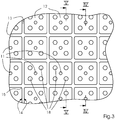
- ein Förderband der Transporteinrichtung in vergrößerter Darstellung,
- Figur 4:
- einen Querschnitt durch das Förderband, entlang der Schnittlinie IV in
Figur 3 und - Figur 5:
- einen anderen Querschnitt durch das Förderband, entlang der Schnittlinie V in
Figur 3 . - In den
Figuren 1 und 2 ist eine Druckmaschine 1 in einem Ausschnitt dargestellt. Die Druckmaschine 1 umfasst einen Druckkopf für Tintenstrahldruck, der zeichnerisch nicht mit dargestellt ist. Außerdem umfasst die Druckmaschine 1 eine Transporteinrichtung 2 zum Transportieren von Druckbogen 3, die in dem Ausschnitt zu sehen ist. Die Transporteinrichtung 2 transportiert die Druckbogen 3 an dem Druckkopf vorbei, welcher dabei die Druckbogen 3 bedruckt. - Die Transporteinrichtung 2 umfasst ein Förderband 4, auf dessen oberem Trum 5 die Druckbogen 3 während ihres Transports liegen. Das Förderband 4 ist endlos und läuft um zwei Rollen 6, von denen die eine das Förderband 4 antreibt und die andere das Förderband 4 umlenkt. Mit einem Pfeil ist eine Richtung 7 angegeben, die der Umlaufrichtung des Förderbandes 4 und der Transportrichtung der Druckbogen 3 entspricht. Vor und hinter der Transporteinrichtung 2 ist jeweils ein Leitblech 8 zum Leiten der Druckbogen 3 angeordnet. Die Transporteinrichtung 2 übernimmt die Druckbogen 3 von dem einen Leitblech 8 und gibt die Druckbogen 3 nach deren Bedruckung an das andere Leitblech 8 ab.
- Zwischen den beiden Rollen 6 ist ein Saugluftkasten 9 angeordnet, der an eine Vakuumquelle 10 angeschlossen ist, die symbolisch dargestellt ist. Das Trum 5 liegt mit seiner Unterseite an dem Saugluftkasten 9 an. Die zu dem Trum 5 weisende Oberseite des Saugluftkastens 9 hat ein Fenster, das zeichnerisch nicht mit dargestellt ist. In das Förderband 4 sind Durchgangsbohrungen eingebracht, die Vakuumöffnungen 11 bilden. Über das erwähnte Fenster im Saugluftkasten 9 werden die daran vorbeilaufenden Vakuumöffnungen 9 mit Vakuum beaufschlagt, indem sie vorübergehend mit der Saugluftquelle 10 strömungstechnisch verbunden werden.
- Die Formate der Druckbogen 3 können sich nicht nur in der Formatlänge, die in der Richtung 7 zu messen ist, sondern auch in der Formatbreite, die senkrecht zur Richtung 7 zu messen ist, voneinander unterscheiden. Im zeichnerisch dargestellten Beispiel unterscheiden sich die Formate der Druckbogen 3 nur in der Formatlänge voneinander. Die Transporteinrichtung 2 hat eine Formatbreiten-Einstelleinrichtung, die zeichnerisch nicht mit dargestellt ist. Die Formatbreiten-Einstelleinrichtung wird eingesetzt bei Formatbreiten, die kleiner als das Maximalformat sind. Bei solchen Formatbreiten gibt es vom Druckbogen 3 nicht abgedeckte Vakuumöffnungen 11, die in Richtung 7 gesehen, links und rechts vom Druckbogen 3 liegen. Damit solche vom Druckbogen 3 nicht abgedeckten Vakuumöffnungen 11 keine Fehlluft ziehen, wird die Formatbreiten-Einstelleinrichtung eingesetzt. Mit der Formatbreiten-Einstelleinrichtung werden die außerhalb der Formatbreite liegenden Vakuumöffnungen 11, die auf der Außenseite des Förderbandes 4 vom Druckbogen 3 nicht abgedeckt sind, auf der Innenseite des Förderbandes 4, zum Beispiel durch zwei verschiebbare Blenden der Formatbreiten-Einstelleinrichtung, abgedeckt.
- In den
Figuren 3 bis 5 ist eine die Druckbogen 3 tragende Oberflächenstruktur des Förderbands 4 im Detail dargestellt. Das Förderband 4 besteht aus Metall, vorzugsweise aus Stahl, was hinsichtlich der Fertigung der Oberflächenstruktur als Ätzstruktur 16 vorteilhaft ist. Die Oberflächenstruktur ist ein Relief und wird durch ein Raster von Näpfchen oder Mulden 12 gebildet. Die Rasterweite des Rasters ist in der Zeichnung übertrieben groß dargestellt, damit die Details besser erkennbar sind. In der Praxis kann die Rasterweite - zum Beispiel bei Druckbogen 3 mit einer Formatlänge von ca. 250 mm - 5 mm betragen. Mit der Rasterweite ist der Abstand zwischen der Mitte einer Mulde 12 und der Mitte der benachbarten Mulde 12 gemeint. Die Tiefe der Mulden 12 kann - zum Beispiel bei einer 0,30 mm betragenden Stärke des Förderbandes 4 (Banddicke) - 0,05 mm bis 0,10 mm betragen. - In den Boden jeder Mulde 12 ist zentral eine der Vakuumöffnungen 11 eingebracht. Zwischen den Mulden 12 verlaufen Dichtungslippen oder Stege 13, die zusammen ein Gitternetz oder Rastergitter bilden. Jede Mulde 12 ist rundum von Stegen 13 begrenzt, welche die Seitenwände der Mulde 12 bilden.
- In der Transportebene 17 der Druckbogen 3 bilden die Stege 13 den ringförmigen Rand der jeweiligen Mulde 12. Dieser Rand könnte eine kreisförmige Kontur haben, jedoch ist die zeichnerisch dargestellte Variante des Randes mit polygonaler Kontur 14 hinsichtlich einer über die ganze Steglänge gleichmäßig dünnen Ausbildung der Stege 13 vorteilhafter. Die gleichmäßig dünne Ausbildung ist wiederum hinsichtlich der Maximierung des offenen Flächenanteils der Mulden 12 und somit eines sicheren pneumatischen Haltens der Druckbogen 3 vorteilhaft. Im zeichnerisch dargestellten Beispiel ist die Kontur 14 viereckig, speziell rechteckig oder quadratisch. Bei zeichnerisch nicht dargestellten Varianten kann die Mulde 12 eine Rautenform mit rhombischem Rand oder eine Wabenform mit hexagonalem Rand haben. Bei allen möglichen Ringformen des Randes, z. B. der quadratischen Ringform, ist es für die Ausbildung des Vakuums in der Mulde 12 wichtig, dass die Ringform ohne Unterbrechung ist, das heißt, als geschlossener Ring verläuft. In allen Fällen ist es hinsichtlich der Stabilität vorteilhaft, wenn die Innenecken 15 der Kontur 14 abgerundet sind.
- In jeder Mulde 12 sind mehrere Stützen oder Vorsprünge 18 in Gleichverteilung um die Vakuumöffnung 11 herum angeordnet. Die Vorsprünge 18 werden durch beim Ätzen stehengebliebene Materialsäulen gebildet und ragen aus dem Boden der Mulde 12. Speziell sind vier Vorsprünge 18 pro Mulde 12 vorhanden, wobei die Vorsprünge 18 auf den Eckpunkten eines imaginären Quadrats angeordnet sind. Die Vorsprünge 18 und die Vakuumöffnung 11 der jeweiligen Mulde 12 sind auf den beiden imaginären Diagonalen der quadratischen Kontur 14 angeordnet, wobei sich die Vakuumöffnung 11 im Schnittpunkt der beiden Diagonalen befindet.
- In den
Figuren 4 und 5 ist erkennbar, dass jeder Vorsprung 18 genau bis zur Transportebene 17 ragt und somit mit den Stegen 13 bündig endet. Die planen Oberseiten der Vorsprünge 18 und der Stege 13 bilden zusammen die Außenfläche des Förderbandes 4, auf der die Druckbogen 3 liegen. Die Vorsprünge 18 dienen zum Abstützen der Druckbogen 13 an deren Kanten oder Rändern. - In
Figur 3 ist erkennbar, dass die Vorsprünge 18 jeweils einen kreisförmigen Querschnitt haben, wobei die Fläche dieses Querschnitts größer als die ebenfalls kreisförmige Querschnittsfläche der Vakuumöffnung 11 ist. Die Vorsprünge 18 sind zylinderförmig. - In
Figur 2 ist erkennbar, dass die Mulden 12 in Längsreihen und Querreihen des Rasters angeordnet sind. Die Längsreihen verlaufen parallel mit der Richtung 7 des Transports und die Querreihen verlaufen senkrecht zu den Längsreihen und zu der Richtung 7. Die Druckbogen 3 werden derart transportiert, dass jeweils die Hinterkante eines vorangehenden Druckbogens 3 und die Vorderkante eines nachfolgenden Druckbogens 3 die Mulden 12 ein und derselben Querreihe überlappen oder in diese Mulden 12 hineinragen. Hierbei ist zwischen der Vorderkante und der Hinterkante der benachbarten Druckbogen 3 ein Abstand gewahrt. - Dadurch, dass die Druckbogen 3 mit der Vorderkante und der Hinterkante oder zumindest mit den kantennahen Randbereichen auf den Vorsprüngen 18 aufliegen und von diesem abgestützt werden, werden die Bogenkanten und auch die Bogenecken sicher am Förderband 4 festgehalten und besteht keine Gefahr eines Aufrichtens oder Umschlagens der Kanten und Ecken. Aufgerichtete oder umgeschlagene Kanten und Ecken würden sonst eine Gefahr für den Tintenstrahl-Druckkopf darstellen, mit dessen Düsenplatte sie beim Vorbeilauf daran kollidieren könnten, wodurch die Düsenplatte beschädigt werden könnte. Das erfindungsgemäße Förderband 4 ist deshalb besonders vorteilhaft in Druckmaschinen 1 mit einem Tintenstrahl-Druckkopf einsetzbar, der bei dem erfindungsgemäßen Förderband 4 besonders nah an das Trum 5 heranreichen kann, was wiederum bezüglich der Druckqualität vorteilhaft ist.
- Bei einer zeichnerisch nicht dargestellten Modifikation sind pro Mulde 12 zwei Vakuumöffnungen 11 vorhanden, die in den Boden der Mulde 12 eingebracht sind. Das heißt, zu der in der Zeichnung dargestellten Vakuumöffnung 11 kommt eine zusätzliche Vakuumöffnung 11 hinzu.
- Die beiden pro Mulde 12 vorgesehenen Vakuumöffnungen 11 haben einen Mittenversatz zueinander, der in Querrichtung des Förderbands 4, also senkrecht zur Richtung 7 (Umlaufrichtung), zu messen ist. Die Mitten der beiden Vakuumöffnungen 11 können zusätzlich auch in Richtung 7 des Umlaufs des Förderbandes 4 zueinander versetzt sein, das müssen sie aber nicht unbedingt.
-
- 1
- Druckmaschine
- 2
- Transporteinrichtung
- 3
- Druckbogen
- 4
- Förderband
- 5
- Trum
- 6
- Rolle
- 7
- Richtung
- 8
- Leitblech
- 9
- Saugluftkasten
- 10
- Vakuumquelle
- 11
- Vakuumöffnung
- 12
- Mulde
- 13
- Steg
- 14
- Kontur
- 15
- Innenecke
- 16
- Ätzstruktur
- 17
- Transportebene
- 18
- Vorsprung
Claims (10)
- Förderband für Druckbogen, umfassend Mulden (12), in denen jeweils Vorsprünge (18) zum Abstützen der Druckbogen (3) und eine Vakuumöffnung (11) angeordnet sind.
- Förderband nach Anspruch 1,
wobei die Vakuumöffnung (11) zwischen den Vorsprüngen (18) angeordnet ist. - Förderband nach Anspruch 1 oder 2,
wobei die Vorsprünge (18) in Gleichverteilung um die Vakuumöffnung (11) angeordnet sind. - Förderband nach einem der Ansprüche 1 bis 3,
wobei zwischen den Mulden (12) Stege (13) angeordnet sind, die zusammen ein Rastergitter bilden. - Förderband nach Anspruch 4,
wobei die Vorsprünge (18) mit den Stegen (13) bündig enden. - Förderband nach einem der Ansprüche 1 bis 5,
wobei die Mulden (12) jeweils einen Rand haben, der eine polygonale Kontur (14) bildet. - Förderband nach Anspruch 6,
wobei die polygonale Kontur (14) quadratisch ist. - Förderband nach Anspruch 6 oder 7
wobei die polygonale Kontur (14) abgerundete Innenecken (15) hat. - Förderband nach einem der Ansprüche 1 bis 8,
wobei die Mulden (12) und Vorsprünge (18) durch eine Ätzstruktur (16) gebildet werden. - Förderband nach einem der Ansprüche 1 bis 9,
wobei das Förderband (4) ein Stahlband ist.
Applications Claiming Priority (1)
| Application Number | Priority Date | Filing Date | Title |
|---|---|---|---|
| DE102016208074.1A DE102016208074A1 (de) | 2016-05-11 | 2016-05-11 | Förderband für Druckbogen |
Publications (2)
| Publication Number | Publication Date |
|---|---|
| EP3243779A1 true EP3243779A1 (de) | 2017-11-15 |
| EP3243779B1 EP3243779B1 (de) | 2020-07-15 |
Family
ID=58536816
Family Applications (1)
| Application Number | Title | Priority Date | Filing Date |
|---|---|---|---|
| EP17165699.4A Active EP3243779B1 (de) | 2016-05-11 | 2017-04-10 | Förderband für druckbogen |
Country Status (3)
| Country | Link |
|---|---|
| EP (1) | EP3243779B1 (de) |
| CN (1) | CN107379790B (de) |
| DE (1) | DE102016208074A1 (de) |
Families Citing this family (3)
| Publication number | Priority date | Publication date | Assignee | Title |
|---|---|---|---|---|
| WO2021014296A1 (en) * | 2019-07-19 | 2021-01-28 | Mamizadeh Hassan | A printing system of security materials and anti-forgery documents with raised printing and process thereof |
| DE102020125412A1 (de) | 2020-09-29 | 2022-03-31 | Koenig & Bauer Ag | Vorrichtung zum Transport von jeweils bis an ihre auf ihre Transportrichtung bezogene Vorderkante und/oder Hinterkante lackierten Blechtafeln |
| DE202023104392U1 (de) * | 2023-08-03 | 2024-11-05 | Neuhäuser GmbH | Fördereinrichtung |
Citations (6)
| Publication number | Priority date | Publication date | Assignee | Title |
|---|---|---|---|---|
| JPS55176246U (de) * | 1979-06-07 | 1980-12-17 | ||
| WO1989008821A1 (en) * | 1988-03-11 | 1989-09-21 | Rastergraphics, Inc. | A paper transport and paper stabilizing system for a raster line printer, plotter or the like |
| WO1997049554A1 (en) * | 1996-06-25 | 1997-12-31 | Marquip, Inc. | Vacuum assisted web drive for corrugator double backer |
| DE10010970A1 (de) * | 1999-03-26 | 2000-10-12 | Heidelberger Druckmasch Ag | Saugbandförderer für eine Bogen verarbeitende Maschine |
| DE102009048928A1 (de) | 2009-10-10 | 2011-04-14 | Steinemann Technology Ag | Vorrichtung zur Bogenführung in einem Tintenstrahldrucker |
| EP2610064A1 (de) * | 2011-12-27 | 2013-07-03 | Fujifilm Corporation | Tintenstrahlaufzeichnungsvorrichtung |
Family Cites Families (9)
| Publication number | Priority date | Publication date | Assignee | Title |
|---|---|---|---|---|
| US2969869A (en) * | 1957-09-12 | 1961-01-31 | Karl A Klingler | Vacuum delivery belt |
| US3861669A (en) * | 1972-06-15 | 1975-01-21 | Tokyo Shibaura Electric Co | Apparatus for feeding sheet-like articles from a stack of articles |
| US3889801A (en) * | 1972-10-26 | 1975-06-17 | Bell & Howell Co | Vacuum conveyor belt with air bearing |
| DE4406739C2 (de) * | 1994-03-02 | 1997-06-19 | Heidelberger Druckmasch Ag | Vorrichtung zum gleichmäßigen Ansaugen eines flächigen Körpers auf einer Unterlage, insbesondere für Druckmaschinen und deren Zusatzgeräte |
| DE29515857U1 (de) * | 1995-10-06 | 1995-12-07 | RRG Industrietechnik GmbH, 45470 Mülheim | Fördervorrichtung |
| DE19839314B4 (de) * | 1998-02-18 | 2007-03-01 | Heidelberger Druckmaschinen Ag | Verfahren und Vorrichtung zum Transport von Bogen mittels mindestens eines Transportbandes, an welchem die Bogen auf dem Transportweg fixiert werden |
| WO2000034158A1 (en) * | 1998-12-08 | 2000-06-15 | The Langston Corporation | Vacuum assist transfer belt |
| KR100788660B1 (ko) * | 2005-01-18 | 2007-12-26 | 삼성전자주식회사 | 화상입출력장치 및 방법 |
| JP2008080526A (ja) * | 2006-09-26 | 2008-04-10 | Brother Ind Ltd | 液体噴射装置 |
-
2016
- 2016-05-11 DE DE102016208074.1A patent/DE102016208074A1/de not_active Withdrawn
-
2017
- 2017-04-10 EP EP17165699.4A patent/EP3243779B1/de active Active
- 2017-05-04 CN CN201710307808.8A patent/CN107379790B/zh active Active
Patent Citations (6)
| Publication number | Priority date | Publication date | Assignee | Title |
|---|---|---|---|---|
| JPS55176246U (de) * | 1979-06-07 | 1980-12-17 | ||
| WO1989008821A1 (en) * | 1988-03-11 | 1989-09-21 | Rastergraphics, Inc. | A paper transport and paper stabilizing system for a raster line printer, plotter or the like |
| WO1997049554A1 (en) * | 1996-06-25 | 1997-12-31 | Marquip, Inc. | Vacuum assisted web drive for corrugator double backer |
| DE10010970A1 (de) * | 1999-03-26 | 2000-10-12 | Heidelberger Druckmasch Ag | Saugbandförderer für eine Bogen verarbeitende Maschine |
| DE102009048928A1 (de) | 2009-10-10 | 2011-04-14 | Steinemann Technology Ag | Vorrichtung zur Bogenführung in einem Tintenstrahldrucker |
| EP2610064A1 (de) * | 2011-12-27 | 2013-07-03 | Fujifilm Corporation | Tintenstrahlaufzeichnungsvorrichtung |
Also Published As
| Publication number | Publication date |
|---|---|
| CN107379790B (zh) | 2020-06-19 |
| EP3243779B1 (de) | 2020-07-15 |
| DE102016208074A1 (de) | 2017-11-16 |
| CN107379790A (zh) | 2017-11-24 |
Similar Documents
| Publication | Publication Date | Title |
|---|---|---|
| DE10300234B3 (de) | Vorrichtung und Verfahren zur Nutzentrennung in einer Maschine zur Herstellung von aus einer Materialbahn ausgeschnittenen Flachmaterialstücken | |
| EP3042767B1 (de) | Saugfläche | |
| EP3243779B1 (de) | Förderband für druckbogen | |
| DE4213387C2 (de) | Papieraustrageinrichtung | |
| DE102019208156A1 (de) | Druckmaschine mit Förderbändern für Bogen | |
| DE60130819T2 (de) | Gerät zum Positionieren von Empfangsmaterial während des Aufbringens eines Tintenbildes darauf | |
| WO2006125239A1 (de) | Haltevorrichtung für tintenstrahldrucker | |
| DE4431488C2 (de) | Bogenführung im Anleger einer Bogendruckmaschine | |
| DE102020129870B4 (de) | Bogendruckmaschine mit Saugband und Abdeckeinrichtung | |
| DE4315511B4 (de) | Sauggreifer für eine Bogenübergabetrommel | |
| EP0028608B1 (de) | Vorrichtung mit magnetisch bewirkter anpresskraft | |
| DE102005016783B4 (de) | Bogenbremse | |
| DE3234155A1 (de) | Vorrichtung zum fuehren und niederhalten eines druckbogens in der transportebene einer druckmaschine | |
| EP2554345B1 (de) | Bogenstanz- und/oder -prägestation mit druckluftbetätigtem Schließrahmen | |
| DE2457069C2 (de) | Vorrichtung zum passergerechten Anlegen von Bogen in Bogenrotationsdruckmaschinen | |
| EP4450434A1 (de) | Förderanlage für einen liegenden transport von blechtafeln | |
| EP1970334A2 (de) | Bogen bearbeitende Maschine mit pneumatischer Transportvorrichtung | |
| EP2149519A1 (de) | Verfahren und Vorrichtung zum Abheben eines Stirndeckels von einem Stirndeckelstapel | |
| DE102007024916A1 (de) | Transportmodul | |
| DE19781152B4 (de) | Vorrichtung zum Transportieren von blattförmigem Material | |
| DE29720989U1 (de) | Bogenführungseinrichtung mit einer Leitfläche in einer Druckmaschine | |
| DE102017208091B4 (de) | Bogenzuführvorrichtung für eine Druckmaschine | |
| DE870564C (de) | Einrichtung zum Bewegen oder zur Steuerung der Bewegung von Bahnen oder Blaettern aus Papier od. dgl. in Druckmaschinen od. dgl. | |
| DE2365668C3 (de) | Vorrichtung zur Verarbeitung bahnförmigen Materials mit einem Rotationsdruckwerk | |
| DE102021103975B4 (de) | Bearbeitungsmaschine mit zumindest einer digitalen Druckeinheit und mit zumindest einem Saugtransportmittel |
Legal Events
| Date | Code | Title | Description |
|---|---|---|---|
| PUAI | Public reference made under article 153(3) epc to a published international application that has entered the european phase |
Free format text: ORIGINAL CODE: 0009012 |
|
| STAA | Information on the status of an ep patent application or granted ep patent |
Free format text: STATUS: THE APPLICATION HAS BEEN PUBLISHED |
|
| AK | Designated contracting states |
Kind code of ref document: A1 Designated state(s): AL AT BE BG CH CY CZ DE DK EE ES FI FR GB GR HR HU IE IS IT LI LT LU LV MC MK MT NL NO PL PT RO RS SE SI SK SM TR |
|
| AX | Request for extension of the european patent |
Extension state: BA ME |
|
| STAA | Information on the status of an ep patent application or granted ep patent |
Free format text: STATUS: REQUEST FOR EXAMINATION WAS MADE |
|
| 17P | Request for examination filed |
Effective date: 20180515 |
|
| RBV | Designated contracting states (corrected) |
Designated state(s): AL AT BE BG CH CY CZ DE DK EE ES FI FR GB GR HR HU IE IS IT LI LT LU LV MC MK MT NL NO PL PT RO RS SE SI SK SM TR |
|
| RAP1 | Party data changed (applicant data changed or rights of an application transferred) |
Owner name: HEIDELBERGER DRUCKMASCHINEN AG |
|
| STAA | Information on the status of an ep patent application or granted ep patent |
Free format text: STATUS: EXAMINATION IS IN PROGRESS |
|
| 17Q | First examination report despatched |
Effective date: 20191025 |
|
| GRAP | Despatch of communication of intention to grant a patent |
Free format text: ORIGINAL CODE: EPIDOSNIGR1 |
|
| STAA | Information on the status of an ep patent application or granted ep patent |
Free format text: STATUS: GRANT OF PATENT IS INTENDED |
|
| INTG | Intention to grant announced |
Effective date: 20200325 |
|
| GRAS | Grant fee paid |
Free format text: ORIGINAL CODE: EPIDOSNIGR3 |
|
| GRAA | (expected) grant |
Free format text: ORIGINAL CODE: 0009210 |
|
| STAA | Information on the status of an ep patent application or granted ep patent |
Free format text: STATUS: THE PATENT HAS BEEN GRANTED |
|
| AK | Designated contracting states |
Kind code of ref document: B1 Designated state(s): AL AT BE BG CH CY CZ DE DK EE ES FI FR GB GR HR HU IE IS IT LI LT LU LV MC MK MT NL NO PL PT RO RS SE SI SK SM TR |
|
| REG | Reference to a national code |
Ref country code: CH Ref legal event code: EP Ref country code: GB Ref legal event code: FG4D Free format text: NOT ENGLISH |
|
| REG | Reference to a national code |
Ref country code: IE Ref legal event code: FG4D Free format text: LANGUAGE OF EP DOCUMENT: GERMAN |
|
| REG | Reference to a national code |
Ref country code: DE Ref legal event code: R096 Ref document number: 502017006159 Country of ref document: DE |
|
| REG | Reference to a national code |
Ref country code: AT Ref legal event code: REF Ref document number: 1290819 Country of ref document: AT Kind code of ref document: T Effective date: 20200815 |
|
| REG | Reference to a national code |
Ref country code: LT Ref legal event code: MG4D |
|
| REG | Reference to a national code |
Ref country code: NL Ref legal event code: MP Effective date: 20200715 |
|
| PG25 | Lapsed in a contracting state [announced via postgrant information from national office to epo] |
Ref country code: GR Free format text: LAPSE BECAUSE OF FAILURE TO SUBMIT A TRANSLATION OF THE DESCRIPTION OR TO PAY THE FEE WITHIN THE PRESCRIBED TIME-LIMIT Effective date: 20201016 Ref country code: BG Free format text: LAPSE BECAUSE OF FAILURE TO SUBMIT A TRANSLATION OF THE DESCRIPTION OR TO PAY THE FEE WITHIN THE PRESCRIBED TIME-LIMIT Effective date: 20201015 Ref country code: NO Free format text: LAPSE BECAUSE OF FAILURE TO SUBMIT A TRANSLATION OF THE DESCRIPTION OR TO PAY THE FEE WITHIN THE PRESCRIBED TIME-LIMIT Effective date: 20201015 Ref country code: SE Free format text: LAPSE BECAUSE OF FAILURE TO SUBMIT A TRANSLATION OF THE DESCRIPTION OR TO PAY THE FEE WITHIN THE PRESCRIBED TIME-LIMIT Effective date: 20200715 Ref country code: FI Free format text: LAPSE BECAUSE OF FAILURE TO SUBMIT A TRANSLATION OF THE DESCRIPTION OR TO PAY THE FEE WITHIN THE PRESCRIBED TIME-LIMIT Effective date: 20200715 Ref country code: HR Free format text: LAPSE BECAUSE OF FAILURE TO SUBMIT A TRANSLATION OF THE DESCRIPTION OR TO PAY THE FEE WITHIN THE PRESCRIBED TIME-LIMIT Effective date: 20200715 Ref country code: PT Free format text: LAPSE BECAUSE OF FAILURE TO SUBMIT A TRANSLATION OF THE DESCRIPTION OR TO PAY THE FEE WITHIN THE PRESCRIBED TIME-LIMIT Effective date: 20201116 Ref country code: ES Free format text: LAPSE BECAUSE OF FAILURE TO SUBMIT A TRANSLATION OF THE DESCRIPTION OR TO PAY THE FEE WITHIN THE PRESCRIBED TIME-LIMIT Effective date: 20200715 Ref country code: LT Free format text: LAPSE BECAUSE OF FAILURE TO SUBMIT A TRANSLATION OF THE DESCRIPTION OR TO PAY THE FEE WITHIN THE PRESCRIBED TIME-LIMIT Effective date: 20200715 |
|
| PG25 | Lapsed in a contracting state [announced via postgrant information from national office to epo] |
Ref country code: LV Free format text: LAPSE BECAUSE OF FAILURE TO SUBMIT A TRANSLATION OF THE DESCRIPTION OR TO PAY THE FEE WITHIN THE PRESCRIBED TIME-LIMIT Effective date: 20200715 Ref country code: PL Free format text: LAPSE BECAUSE OF FAILURE TO SUBMIT A TRANSLATION OF THE DESCRIPTION OR TO PAY THE FEE WITHIN THE PRESCRIBED TIME-LIMIT Effective date: 20200715 Ref country code: RS Free format text: LAPSE BECAUSE OF FAILURE TO SUBMIT A TRANSLATION OF THE DESCRIPTION OR TO PAY THE FEE WITHIN THE PRESCRIBED TIME-LIMIT Effective date: 20200715 Ref country code: IS Free format text: LAPSE BECAUSE OF FAILURE TO SUBMIT A TRANSLATION OF THE DESCRIPTION OR TO PAY THE FEE WITHIN THE PRESCRIBED TIME-LIMIT Effective date: 20201115 |
|
| PG25 | Lapsed in a contracting state [announced via postgrant information from national office to epo] |
Ref country code: NL Free format text: LAPSE BECAUSE OF FAILURE TO SUBMIT A TRANSLATION OF THE DESCRIPTION OR TO PAY THE FEE WITHIN THE PRESCRIBED TIME-LIMIT Effective date: 20200715 |
|
| REG | Reference to a national code |
Ref country code: DE Ref legal event code: R097 Ref document number: 502017006159 Country of ref document: DE |
|
| PG25 | Lapsed in a contracting state [announced via postgrant information from national office to epo] |
Ref country code: RO Free format text: LAPSE BECAUSE OF FAILURE TO SUBMIT A TRANSLATION OF THE DESCRIPTION OR TO PAY THE FEE WITHIN THE PRESCRIBED TIME-LIMIT Effective date: 20200715 Ref country code: DK Free format text: LAPSE BECAUSE OF FAILURE TO SUBMIT A TRANSLATION OF THE DESCRIPTION OR TO PAY THE FEE WITHIN THE PRESCRIBED TIME-LIMIT Effective date: 20200715 Ref country code: CZ Free format text: LAPSE BECAUSE OF FAILURE TO SUBMIT A TRANSLATION OF THE DESCRIPTION OR TO PAY THE FEE WITHIN THE PRESCRIBED TIME-LIMIT Effective date: 20200715 Ref country code: EE Free format text: LAPSE BECAUSE OF FAILURE TO SUBMIT A TRANSLATION OF THE DESCRIPTION OR TO PAY THE FEE WITHIN THE PRESCRIBED TIME-LIMIT Effective date: 20200715 Ref country code: IT Free format text: LAPSE BECAUSE OF FAILURE TO SUBMIT A TRANSLATION OF THE DESCRIPTION OR TO PAY THE FEE WITHIN THE PRESCRIBED TIME-LIMIT Effective date: 20200715 Ref country code: SM Free format text: LAPSE BECAUSE OF FAILURE TO SUBMIT A TRANSLATION OF THE DESCRIPTION OR TO PAY THE FEE WITHIN THE PRESCRIBED TIME-LIMIT Effective date: 20200715 |
|
| PLBE | No opposition filed within time limit |
Free format text: ORIGINAL CODE: 0009261 |
|
| STAA | Information on the status of an ep patent application or granted ep patent |
Free format text: STATUS: NO OPPOSITION FILED WITHIN TIME LIMIT |
|
| PG25 | Lapsed in a contracting state [announced via postgrant information from national office to epo] |
Ref country code: AL Free format text: LAPSE BECAUSE OF FAILURE TO SUBMIT A TRANSLATION OF THE DESCRIPTION OR TO PAY THE FEE WITHIN THE PRESCRIBED TIME-LIMIT Effective date: 20200715 |
|
| 26N | No opposition filed |
Effective date: 20210416 |
|
| PG25 | Lapsed in a contracting state [announced via postgrant information from national office to epo] |
Ref country code: SK Free format text: LAPSE BECAUSE OF FAILURE TO SUBMIT A TRANSLATION OF THE DESCRIPTION OR TO PAY THE FEE WITHIN THE PRESCRIBED TIME-LIMIT Effective date: 20200715 |
|
| PG25 | Lapsed in a contracting state [announced via postgrant information from national office to epo] |
Ref country code: SI Free format text: LAPSE BECAUSE OF FAILURE TO SUBMIT A TRANSLATION OF THE DESCRIPTION OR TO PAY THE FEE WITHIN THE PRESCRIBED TIME-LIMIT Effective date: 20200715 |
|
| PG25 | Lapsed in a contracting state [announced via postgrant information from national office to epo] |
Ref country code: MC Free format text: LAPSE BECAUSE OF FAILURE TO SUBMIT A TRANSLATION OF THE DESCRIPTION OR TO PAY THE FEE WITHIN THE PRESCRIBED TIME-LIMIT Effective date: 20200715 |
|
| GBPC | Gb: european patent ceased through non-payment of renewal fee |
Effective date: 20210410 |
|
| PG25 | Lapsed in a contracting state [announced via postgrant information from national office to epo] |
Ref country code: LU Free format text: LAPSE BECAUSE OF NON-PAYMENT OF DUE FEES Effective date: 20210410 |
|
| REG | Reference to a national code |
Ref country code: BE Ref legal event code: MM Effective date: 20210430 |
|
| PG25 | Lapsed in a contracting state [announced via postgrant information from national office to epo] |
Ref country code: GB Free format text: LAPSE BECAUSE OF NON-PAYMENT OF DUE FEES Effective date: 20210410 Ref country code: FR Free format text: LAPSE BECAUSE OF NON-PAYMENT OF DUE FEES Effective date: 20210430 Ref country code: LI Free format text: LAPSE BECAUSE OF NON-PAYMENT OF DUE FEES Effective date: 20210430 Ref country code: CH Free format text: LAPSE BECAUSE OF NON-PAYMENT OF DUE FEES Effective date: 20210430 |
|
| PG25 | Lapsed in a contracting state [announced via postgrant information from national office to epo] |
Ref country code: IE Free format text: LAPSE BECAUSE OF NON-PAYMENT OF DUE FEES Effective date: 20210410 |
|
| PG25 | Lapsed in a contracting state [announced via postgrant information from national office to epo] |
Ref country code: IS Free format text: LAPSE BECAUSE OF FAILURE TO SUBMIT A TRANSLATION OF THE DESCRIPTION OR TO PAY THE FEE WITHIN THE PRESCRIBED TIME-LIMIT Effective date: 20201115 |
|
| PG25 | Lapsed in a contracting state [announced via postgrant information from national office to epo] |
Ref country code: BE Free format text: LAPSE BECAUSE OF NON-PAYMENT OF DUE FEES Effective date: 20210430 |
|
| PG25 | Lapsed in a contracting state [announced via postgrant information from national office to epo] |
Ref country code: HU Free format text: LAPSE BECAUSE OF FAILURE TO SUBMIT A TRANSLATION OF THE DESCRIPTION OR TO PAY THE FEE WITHIN THE PRESCRIBED TIME-LIMIT; INVALID AB INITIO Effective date: 20170410 |
|
| P01 | Opt-out of the competence of the unified patent court (upc) registered |
Effective date: 20230427 |
|
| REG | Reference to a national code |
Ref country code: AT Ref legal event code: MM01 Ref document number: 1290819 Country of ref document: AT Kind code of ref document: T Effective date: 20220410 |
|
| PG25 | Lapsed in a contracting state [announced via postgrant information from national office to epo] |
Ref country code: CY Free format text: LAPSE BECAUSE OF FAILURE TO SUBMIT A TRANSLATION OF THE DESCRIPTION OR TO PAY THE FEE WITHIN THE PRESCRIBED TIME-LIMIT Effective date: 20200715 |
|
| PG25 | Lapsed in a contracting state [announced via postgrant information from national office to epo] |
Ref country code: AT Free format text: LAPSE BECAUSE OF NON-PAYMENT OF DUE FEES Effective date: 20220410 |
|
| PG25 | Lapsed in a contracting state [announced via postgrant information from national office to epo] |
Ref country code: MK Free format text: LAPSE BECAUSE OF FAILURE TO SUBMIT A TRANSLATION OF THE DESCRIPTION OR TO PAY THE FEE WITHIN THE PRESCRIBED TIME-LIMIT Effective date: 20200715 |
|
| PG25 | Lapsed in a contracting state [announced via postgrant information from national office to epo] |
Ref country code: TR Free format text: LAPSE BECAUSE OF FAILURE TO SUBMIT A TRANSLATION OF THE DESCRIPTION OR TO PAY THE FEE WITHIN THE PRESCRIBED TIME-LIMIT Effective date: 20200715 |
|
| PG25 | Lapsed in a contracting state [announced via postgrant information from national office to epo] |
Ref country code: MT Free format text: LAPSE BECAUSE OF FAILURE TO SUBMIT A TRANSLATION OF THE DESCRIPTION OR TO PAY THE FEE WITHIN THE PRESCRIBED TIME-LIMIT Effective date: 20200715 |
|
| PGFP | Annual fee paid to national office [announced via postgrant information from national office to epo] |
Ref country code: DE Payment date: 20250430 Year of fee payment: 9 |