EP3240608B1 - Indicateur d'avertissement avancé pour des dispositifs médicaux d'urgence - Google Patents
Indicateur d'avertissement avancé pour des dispositifs médicaux d'urgence Download PDFInfo
- Publication number
- EP3240608B1 EP3240608B1 EP15825967.1A EP15825967A EP3240608B1 EP 3240608 B1 EP3240608 B1 EP 3240608B1 EP 15825967 A EP15825967 A EP 15825967A EP 3240608 B1 EP3240608 B1 EP 3240608B1
- Authority
- EP
- European Patent Office
- Prior art keywords
- emergency medical
- failure
- operational
- indicator
- readiness
- Prior art date
- Legal status (The legal status is an assumption and is not a legal conclusion. Google has not performed a legal analysis and makes no representation as to the accuracy of the status listed.)
- Active
Links
- 238000012360 testing method Methods 0.000 claims description 61
- 238000004458 analytical method Methods 0.000 claims description 34
- 238000000034 method Methods 0.000 claims description 33
- 230000015556 catabolic process Effects 0.000 claims description 15
- 238000006731 degradation reaction Methods 0.000 claims description 15
- 230000002028 premature Effects 0.000 claims description 15
- 238000002560 therapeutic procedure Methods 0.000 claims description 12
- 239000003990 capacitor Substances 0.000 claims description 10
- 230000004913 activation Effects 0.000 claims description 7
- 238000012544 monitoring process Methods 0.000 description 14
- 230000007704 transition Effects 0.000 description 11
- 230000001960 triggered effect Effects 0.000 description 11
- 238000010586 diagram Methods 0.000 description 10
- 238000003860 storage Methods 0.000 description 9
- 230000000007 visual effect Effects 0.000 description 7
- 230000008439 repair process Effects 0.000 description 5
- 238000013461 design Methods 0.000 description 4
- 230000006870 function Effects 0.000 description 4
- 230000003287 optical effect Effects 0.000 description 4
- 230000007423 decrease Effects 0.000 description 3
- 238000001514 detection method Methods 0.000 description 3
- 230000008569 process Effects 0.000 description 3
- 230000009467 reduction Effects 0.000 description 3
- 230000004044 response Effects 0.000 description 3
- 239000004065 semiconductor Substances 0.000 description 3
- 230000008901 benefit Effects 0.000 description 2
- 238000013194 cardioversion Methods 0.000 description 2
- 230000007547 defect Effects 0.000 description 2
- 238000005516 engineering process Methods 0.000 description 2
- 238000012986 modification Methods 0.000 description 2
- 230000004048 modification Effects 0.000 description 2
- 238000011084 recovery Methods 0.000 description 2
- 230000035939 shock Effects 0.000 description 2
- 230000001360 synchronised effect Effects 0.000 description 2
- 206010011906 Death Diseases 0.000 description 1
- 208000032365 Electromagnetic interference Diseases 0.000 description 1
- 206010063601 Exposure to extreme temperature Diseases 0.000 description 1
- 239000004743 Polypropylene Substances 0.000 description 1
- 206010049418 Sudden Cardiac Death Diseases 0.000 description 1
- 230000003213 activating effect Effects 0.000 description 1
- 230000005540 biological transmission Effects 0.000 description 1
- 230000004397 blinking Effects 0.000 description 1
- JJWKPURADFRFRB-UHFFFAOYSA-N carbonyl sulfide Chemical compound O=C=S JJWKPURADFRFRB-UHFFFAOYSA-N 0.000 description 1
- 230000008859 change Effects 0.000 description 1
- 238000004590 computer program Methods 0.000 description 1
- 230000007797 corrosion Effects 0.000 description 1
- 238000005260 corrosion Methods 0.000 description 1
- 238000005336 cracking Methods 0.000 description 1
- 238000004146 energy storage Methods 0.000 description 1
- 230000007613 environmental effect Effects 0.000 description 1
- 239000011888 foil Substances 0.000 description 1
- PCHJSUWPFVWCPO-UHFFFAOYSA-N gold Chemical compound [Au] PCHJSUWPFVWCPO-UHFFFAOYSA-N 0.000 description 1
- 239000010931 gold Substances 0.000 description 1
- 229910052737 gold Inorganic materials 0.000 description 1
- 238000012423 maintenance Methods 0.000 description 1
- 238000004519 manufacturing process Methods 0.000 description 1
- 238000004806 packaging method and process Methods 0.000 description 1
- 230000000737 periodic effect Effects 0.000 description 1
- 230000002093 peripheral effect Effects 0.000 description 1
- 238000007747 plating Methods 0.000 description 1
- -1 polypropylene Polymers 0.000 description 1
- 229920001155 polypropylene Polymers 0.000 description 1
- 238000012545 processing Methods 0.000 description 1
- 238000002633 shock therapy Methods 0.000 description 1
- 238000004904 shortening Methods 0.000 description 1
- 229910000679 solder Inorganic materials 0.000 description 1
- 239000007787 solid Substances 0.000 description 1
- 208000014221 sudden cardiac arrest Diseases 0.000 description 1
- 230000008646 thermal stress Effects 0.000 description 1
Images
Classifications
-
- A—HUMAN NECESSITIES
- A61—MEDICAL OR VETERINARY SCIENCE; HYGIENE
- A61N—ELECTROTHERAPY; MAGNETOTHERAPY; RADIATION THERAPY; ULTRASOUND THERAPY
- A61N1/00—Electrotherapy; Circuits therefor
- A61N1/18—Applying electric currents by contact electrodes
- A61N1/32—Applying electric currents by contact electrodes alternating or intermittent currents
- A61N1/38—Applying electric currents by contact electrodes alternating or intermittent currents for producing shock effects
- A61N1/39—Heart defibrillators
- A61N1/3904—External heart defibrillators [EHD]
-
- A—HUMAN NECESSITIES
- A61—MEDICAL OR VETERINARY SCIENCE; HYGIENE
- A61N—ELECTROTHERAPY; MAGNETOTHERAPY; RADIATION THERAPY; ULTRASOUND THERAPY
- A61N1/00—Electrotherapy; Circuits therefor
- A61N1/18—Applying electric currents by contact electrodes
- A61N1/32—Applying electric currents by contact electrodes alternating or intermittent currents
- A61N1/38—Applying electric currents by contact electrodes alternating or intermittent currents for producing shock effects
- A61N1/39—Heart defibrillators
- A61N1/3925—Monitoring; Protecting
-
- A—HUMAN NECESSITIES
- A61—MEDICAL OR VETERINARY SCIENCE; HYGIENE
- A61N—ELECTROTHERAPY; MAGNETOTHERAPY; RADIATION THERAPY; ULTRASOUND THERAPY
- A61N1/00—Electrotherapy; Circuits therefor
- A61N1/18—Applying electric currents by contact electrodes
- A61N1/32—Applying electric currents by contact electrodes alternating or intermittent currents
- A61N1/38—Applying electric currents by contact electrodes alternating or intermittent currents for producing shock effects
- A61N1/39—Heart defibrillators
- A61N1/3993—User interfaces for automatic external defibrillators
-
- G—PHYSICS
- G16—INFORMATION AND COMMUNICATION TECHNOLOGY [ICT] SPECIALLY ADAPTED FOR SPECIFIC APPLICATION FIELDS
- G16H—HEALTHCARE INFORMATICS, i.e. INFORMATION AND COMMUNICATION TECHNOLOGY [ICT] SPECIALLY ADAPTED FOR THE HANDLING OR PROCESSING OF MEDICAL OR HEALTHCARE DATA
- G16H20/00—ICT specially adapted for therapies or health-improving plans, e.g. for handling prescriptions, for steering therapy or for monitoring patient compliance
- G16H20/40—ICT specially adapted for therapies or health-improving plans, e.g. for handling prescriptions, for steering therapy or for monitoring patient compliance relating to mechanical, radiation or invasive therapies, e.g. surgery, laser therapy, dialysis or acupuncture
-
- G—PHYSICS
- G16—INFORMATION AND COMMUNICATION TECHNOLOGY [ICT] SPECIALLY ADAPTED FOR SPECIFIC APPLICATION FIELDS
- G16H—HEALTHCARE INFORMATICS, i.e. INFORMATION AND COMMUNICATION TECHNOLOGY [ICT] SPECIALLY ADAPTED FOR THE HANDLING OR PROCESSING OF MEDICAL OR HEALTHCARE DATA
- G16H40/00—ICT specially adapted for the management or administration of healthcare resources or facilities; ICT specially adapted for the management or operation of medical equipment or devices
- G16H40/40—ICT specially adapted for the management or administration of healthcare resources or facilities; ICT specially adapted for the management or operation of medical equipment or devices for the management of medical equipment or devices, e.g. scheduling maintenance or upgrades
-
- G—PHYSICS
- G16—INFORMATION AND COMMUNICATION TECHNOLOGY [ICT] SPECIALLY ADAPTED FOR SPECIFIC APPLICATION FIELDS
- G16Z—INFORMATION AND COMMUNICATION TECHNOLOGY [ICT] SPECIALLY ADAPTED FOR SPECIFIC APPLICATION FIELDS, NOT OTHERWISE PROVIDED FOR
- G16Z99/00—Subject matter not provided for in other main groups of this subclass
-
- A—HUMAN NECESSITIES
- A61—MEDICAL OR VETERINARY SCIENCE; HYGIENE
- A61B—DIAGNOSIS; SURGERY; IDENTIFICATION
- A61B2560/00—Constructional details of operational features of apparatus; Accessories for medical measuring apparatus
- A61B2560/02—Operational features
- A61B2560/0266—Operational features for monitoring or limiting apparatus function
- A61B2560/0276—Determining malfunction
-
- G—PHYSICS
- G01—MEASURING; TESTING
- G01R—MEASURING ELECTRIC VARIABLES; MEASURING MAGNETIC VARIABLES
- G01R31/00—Arrangements for testing electric properties; Arrangements for locating electric faults; Arrangements for electrical testing characterised by what is being tested not provided for elsewhere
- G01R31/28—Testing of electronic circuits, e.g. by signal tracer
- G01R31/2832—Specific tests of electronic circuits not provided for elsewhere
- G01R31/2836—Fault-finding or characterising
-
- G—PHYSICS
- G16—INFORMATION AND COMMUNICATION TECHNOLOGY [ICT] SPECIALLY ADAPTED FOR SPECIFIC APPLICATION FIELDS
- G16H—HEALTHCARE INFORMATICS, i.e. INFORMATION AND COMMUNICATION TECHNOLOGY [ICT] SPECIALLY ADAPTED FOR THE HANDLING OR PROCESSING OF MEDICAL OR HEALTHCARE DATA
- G16H40/00—ICT specially adapted for the management or administration of healthcare resources or facilities; ICT specially adapted for the management or operation of medical equipment or devices
- G16H40/60—ICT specially adapted for the management or administration of healthcare resources or facilities; ICT specially adapted for the management or operation of medical equipment or devices for the operation of medical equipment or devices
- G16H40/63—ICT specially adapted for the management or administration of healthcare resources or facilities; ICT specially adapted for the management or operation of medical equipment or devices for the operation of medical equipment or devices for local operation
Definitions
- the present invention generally relates to emergency medical devices (e.g., an external defibrillator/monitor).
- the present invention specifically relates to an advanced warning of a pending failure of an operationally ready emergency medical device.
- An emergency medical device e.g., an external defibrillator/monitor
- An emergency medical device is used in emergency lifesaving situations where seconds count. For example, when someone succumbs to a sudden cardiac arrest, the likelihood of resuscitation decreases each minute thereafter. Thus, it is critically important for the emergency medical device to be ready for use when it is needed. Consequently, device readiness indicators are commonly used in emergency medical devices to inform the user whether or not the emergency medical device is ready-for-use.
- an emergency medical device In practice, many emergency medical devices are turned-off most of the time and standard protocol mandates a periodic assessment of whether the emergency medical device is ready-for-use. To this end, an emergency medical device typically performs automatic self-tests on an hourly or daily basis when the emergency medical device is turned off, but has power available to conduct the self-tests.
- the device readiness indicator provides visual and/or auditory signals informative of either a pass result or a fail result of the self-tests. For example, the device readiness indicator may be displayed as a green check mark icon to indicate a ready-for-use pass result or as a red X mark to indicate a not-ready-for-use failed result.
- a limitation of this scheme is that there is no advanced warning of a pending failure of a ready-for-use emergency medical device.
- the device readiness indicator will indicate the emergency medical device is ready-for-use until self-tests indicate the emergency medical device is no longer ready-for-use.
- designers of emergency medical devices are constrained to characterize marginal test results as failures, with the possible implication of a false failure that needlessly takes a properly functioning emergency medical device out of service.
- a further consequence of this Boolean indicator is that a subsystem monitoring of the emergency medical device fails to detect condition(s) that indicate the emergency medical device is likely to operationally fail in the near future.
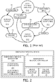
- an illustrated operational readiness assessment state diagram consists of a self-testing/analysis state S10, a subsystem monitoring state S11, an error analysis state S12 and a service/repair state S13 for assessing the operational readiness of the emergency medical device.
- Self-testing/analysis state S10 involves an execution of various self-testing by the emergency medical device of each subsystem of the emergency medical device.
- a subsystem of the emergency medical device employs operational components for executing an emergency medical procedure including, but not limited to, an electrocardiogram monitoring procedure, a defibrillation shock therapy procedure, a synchronized cardioversion therapy procedure and a transcutaneous pacing therapy procedure.
- the self-testing of such operational components involves a delineation of a hard functional limit between being deemed either operationally ready or inoperable for purposes of the associated emergency medical procedure.
- the emergency medical device is triggered to transition T1 to service/repair state S13 whereby the emergency medical device indicates a service/repair is needed for the emergency medical device (e.g., a red X mark icon is activated).
- the emergency medical device is triggered to transition T2 to subsystem monitoring state S11 whereby the emergency medical device indicates all subsystems are ready-for-use (“RFU”) (e.g., a green check mark icon is activated).
- REU ready-for-use
- the emergency medical device While waiting for use or actually in use during subsystem monitoring state S11, the emergency medical device will be triggered to transition T3 to error analysis state S12 when an error by a subsystem occurs that threatens the operational readiness of the emergency medical device.
- the error may be a recoverable error or non-recoverable error (i.e., a failure).
- the emergency medical device is triggered to transition T4 back to subsystem monitoring state S11.
- emergency medical device If the emergency medical device is unable to recover from an error but is reinitiated nonetheless by an operator or automatically, then emergency medical device is triggered to transition T5 to self-testing/analysis state S10.
- the emergency medical device If the emergency medical device has failed subsystem(s) without being reinitialized, then the emergency medical device is triggered to transition T6 to service/repair state S13.
- the operational readiness assessment state diagram may be implemented in various modes, but regardless the subject state diagram fails to detect condition(s) that indicate a subsystem of the emergency medical device is likely to operationally fail in the near future.
- WO2014/097035 discloses a self-testing defibrillator in which the premature degradation of a component is determined by the reception of information from a remote location about the failure of similar operational components.
- the system detects likely operational failure in the near future of a subsystem by recording the number of changes of the battery, which itself is indicative of the defibrillator nearing the end of its design life where a device failure becomes more likely.
- WO2014/033605 discloses self-testing in a defibrillator and a display or audible alarm when failure is likely.
- US2011/0190839A discloses warnings, by a blinking red light supplemented by a voice prompt, of low battery charge in an AED, from self-testing.
- US2013/0317560A discloses warnings, by audible and visible alarms, of low battery charge in an AED, from self-testing.
- the present invention incorporates a predicative failure analysis within the emergency medical device to detect condition(s) indicative of likely operational failure in the near future of operational component(s) of the emergency medical subsystem(s).
- an emergency medical device e.g., an external defibrillator/monitor
- an emergency medical subsystem for executing an emergency medical procedure (e.g., a monitoring subsystem or a therapy subsystem)
- an emergency medical controller for controlling an activation of the emergency medical subsystem.
- the subsystem includes one or more operational components.
- the controller conditionally actuates a device readiness indicator (e.g., auditory or visual) indicative of an operational readiness of the operational component(s), and conditionally actuate a failure warning indicator (e.g., auditory or visual) indicative of a pending failure of the operational component(s).
- a device readiness indicator e.g., auditory or visual
- a failure warning indicator e.g., auditory or visual
- the failure warning indicator may be actuated based on a predictive failure analysis of a premature degradation of the operational component(s), a repeated occurrence of error conditions of the operational component(s) (particularly recoverable error conditions), and a shortened reliable life of the operational component(s).
- the "device readiness indicator” and the “failure warning indicator” may be segregated indicators (e.g., the device readiness indicator being a dedicated visual indicator and the failure warning indicator being displayed on a user interface) or integrated indicators (e.g., the failure warning indicator being a flashing of the dedicated visual indicator).
- controller broadly encompasses all structural configurations of an application specific main board or an application specific integrated circuit housed within or linked to an emergency medical device for controlling an application of various inventive principles of the present invention as subsequently described herein.
- the structural configuration of the controller may include, but is not limited to, processor(s), computer-usable/computer readable storage medium(s), an operating system, application module(s), peripheral device controller(s), slot(s) and port(s).
- application module broadly encompasses an electronic circuit or an executable program (e.g., executable software and/firmware) for executing a specific application.
- a second form of the present invention is a method of operating the emergency medical device.
- the method involves the emergency medical controller conditionally generating a device readiness indicator indicative of an operational readiness of the operational component(s) to execute an emergency medical procedure, and the emergency medical controller conditionally generating a failure warning indicator indicative of a pending failure of the operational readiness of the operational component(s) to execute the emergency medical procedure.
- exemplary embodiments of the present invention will be provided herein directed to an implementation of a predictive failure analysis by an emergency medical controller of the present invention.
- an emergency medical device 20 e.g., an external defibrillator/monitor
- an X number of emergency medical subsystems 21, X ⁇ 1 for executing an X number of emergency medical procedures.
- subsystems 21 include, but are not limited to:
- Each subsystem 21 employs a Y number of operational components structurally assembled to execute the corresponding emergency medical procedure, Y ⁇ 1.
- operational components 22 include, but are not limited to, electronic components, mechanical components and electromechanical components currently utilized in commercially available emergency medical devices (e.g., Philips HeartStart MRx and XL+ defibrillators/monitors).
- Emergency medical device 20 further employs a Z number of emergency medical controller 23, Z ⁇ 1, for controlling an activation of subsystem(s) 21 in executing the emergency medical procedure(s).
- each controller 23 may employ an operating system module as known in the art for overall device control and various application modules for self-testing, predicative failure analyzing and activating subsystem(s) 21. Examples of application modules include, but are not limited to:
- a controller 23 actuates a device readiness indicator 24 indicating either:
- device readiness indicator 24 may have various structures including, but not limited to:
- a controller 23 actuates a failure warning indicator 25 upon a detection by the module of condition(s) indicating a likely operational failure in the near future of subsystem(s) 21 and controller 23.
- condition(s) indicating a likely operational failure in the near future of subsystem(s) 21 and controller 23.
- Such conditions include, but are not limited to:
- failure warning indicator 25 may also have various structures including, but not limited to:
- a failure warning state diagram consists of self-testing/analysis state S10 ( FIG. 1 ), subsystem monitoring state S11 ( FIG. 1 ), error analysis state S12 ( FIG. 1 ) and a novel and unique predictive failure analysis state S14.
- self-testing/analysis state S10 involves an execution of various self-testing by the emergency medical device of each subsystem of the emergency medical device.
- Controller 23 is triggered to transition T7 to predictive failure analysis state S14 upon full execution of the self-tests whereby the test results are analyzed for any indication of a premature degradation of operational component(s) 22 and any error conditions are analyzed for repeated occurrences of a particular error condition or related error conditions.
- Premature Degradation The automated self-tests are typically designed with hard-failure limits to determine the pass/fail results of the test. However, not every failure mode easily falls into buckets of good or bad, because there will be instances where components will degrade over the product lifetime and will slowly pass through the pass/fail boundary of the ready-for-use tests.
- soft-failure limits may be used as predictors of future failures whereby test results outside the hard-failure limits would continue to result in failed test result and whereby test results outside the soft-failure limits but inside the hard-failure limits would result in early failure warnings.
- a typical lifecycle of many types of operational components 22 has three (3) distinct periods including an infant mortality I, a normal life N and end of life E.
- subsystems 21 may be "burned in” and/or operational components 22 are screened during manufacturing.
- a device design target is for a normal life N of each operational component 22 to extend further than the expected life of the overall device 20.
- a popular technology for defibrillator capacitors includes the use of metalized dry-film polypropylene energy storage capacitors. These capacitors exhibit a self-healing property where small defects in the film are removed by clearing away the affected foil area. In a high-pulse application, such as defibrillation, the mechanical and thermal stresses of normal use will occasionally create new fault sites, which will also be cleared. This results in a very small gradual decrease in capacitor value. By design, these decreases are so small that over the product lifetime, capacitors are expected to remain within rated tolerance. It is possible however that some capacitors which are subjected to conditions of extreme use, or extreme environmental conditions, may exhibit a capacitance loss which is sufficient to exceed the hard-failure limits ("HFL") of the device self-tests.
- HFL hard-failure limits
- HFL hard-failure limit
- SFL soft-failure limit set above the hard-failure limit (“HFL”) and below a nominal expected variance (“NVE”) in terms of life expectancy of an operational component 22 provides an indication that device 20 is still ready-for-use, but should be serviced soon if operational component(s) 22 are outside the soft-failure limit.
- Error Condition(s) During device self-test, error conditions might be detected that are not serious enough to be considered as device failures. Examples of such errors are intermittent and recoverable error conditions. Specifically, intermittent errors might be caused by electro-magnetic interference from random noise, cosmic rays or other nearby electronic equipment. Recoverable errors might include software error conditions that can be cleared by rebooting, or data transmission errors where retransmission is possible.
- controller 23 When device 20 recovers from an error condition, controller 23 will continue to show device 20 is ready-for-use via indicator 24. However, if many instances of a specific recoverable error condition are observed over a short period of time, the likelihood increases that the root cause of the error is a real device failure or a latent design defect. Additionally, device performance may be impacted if the rate of occurrence of recoverable errors conditions increases.
- controller 23 is triggered to transition T8 to monitoring/analysis states S11/S12 upon determining a failure warning status derived from the analysis of a premature degradation of operational component(s) 22 and any repeated occurrences of error condition(s).
- the failure warning status is a generation or a non-generation of failure warning indicator 25.
- controller 23 is periodically triggered to transition T9 back to predicative failure analysis state S 14 for analyzing new or additional occurrence(s) of error condition(s) and usage patterns of specific individual component(s) 22.
- Error Condition(s) During normal operation of device 20, error conditions might be detected that are not serious enough to be considered as device failures, particularly recoverable error conditions. Again, any repeated occurrence of a particular error condition or related error conditions is therefore analyzed for any indication of a pending device failure.
- connectors are designed to withstand a finite number of connect/disconnect cycles whereby each connect/disconnect cycle may cause a small amount of friction wear on contact surfaces eventually wearing off gold plating needed for good electrical contact.
- the connectors that would be employed are rated for the expected usage. However, in extreme usage conditions, they could fail.
- the usage pattern of some or all operational component(s) 22 are analyzed to ascertain if the useful life of such component(s) has been shortened.
- controller 23 is again triggered to transition T8 to monitoring/analysis states S11/S12 upon determining a failure warning status derived from the analysis of any repeated occurrences of error condition(s) and of component usage patterns.
- the failure warning status is a generation or a non-generation of failure warning indicator 25.
- controller 23 may be triggered to transition T10 back to self-testing/analysis state S10 upon re-initiation of device 20 to overcome a non-recoverable error or failure of device 20.
- the test results are again analyzed for any indication of a premature degradation of operational component(s) 22 and any test error conditions are again analyzed for repeated occurrences of any particular error condition or related error conditions.
- the failure warning state diagram of FIG. 3 may be implemented in various modes by a controller 23, but regardless the subject state diagram detects condition(s) that indicate a subsystem 21 of the emergency medical device 20 is likely to operationally fail in the near future.
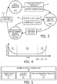
- FIG. 5 illustrates an exemplary defibrillator controller 30 employing a monitoring module 31 for controlling an activation of an ECG module subsystem and a therapy module 32 for controlling an activation of a defibrillation therapy subsystem.
- Defibrillation controller 30 further employs a self-assessment module 33 for executing self-testing and predictive failure analysis of the subsystems.
- self-assessment module 33 may consist of sub-modules for separately executing the self-testing and predictive failure analysis of the subsystems, or may be a single module for integrally executing the self-testing and predictive failure analysis of the subsystems.
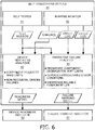
- FIG. 6 illustrates an embodiment 40 of self-assessment module 33 integrally executing the self-testing and predictive failure analysis of the subsystems.
- self-assessment module 40 employs a self-tester 41, a runtime monitor 42, a device readiness analyzer 43 and a predicative failure analyzer 44. Module 40 will described based on data flow between components 41-44.
- Self-tester 41 executes known self-tests to ensure all subsystems are functioning properly. These self-tests are automatically initiated periodically when the device has power but is turned off (e.g., not in clinical use). The self-test produces pass/fail results inclusive of any occurrence of recoverable error condition(s) that are communicated to analyzers 43 and 44 directly or via storage retrieval.
- Runtime monitor 42 monitors the device for any occurrence of an error condition, particularly a failure, as the device is turned on (e.g., in clinical use). Upon detection of an error condition, runtime error monitor 42 will initiate steps necessary to attempt a recovery of the error condition, and logs the condition(s) and recovery effort(s). An error condition is communicated to device readiness analyzer 43 directly or via storage retrieval, and the error log is communicated to predicative failure analyzer 44 directly or via storage retrieval.
- Runtime monitor 42 further generates a usage log informative of various component usage patterns including, but not limited to:
- Runtime monitor 42 communicates the usage log to predictive failure analyzer 45 directly or via storage retrieval.
- Device readiness analyzer 43 analyzes the test results against hard failure limits and analyzes the errors to ascertain as known in the art if the device is ready-for-use or has a failure that requires immediate servicing, and applies a readiness signal to a device readiness indicator 50 (e.g., a light, a speaker, etc.) to actuate/energize indicator 50 in indicating the device is operationally ready for clinical use or inoperable for clinical use and is need of immediate service.
- a device readiness indicator 50 e.g., a light, a speaker, etc.
- predictive failure analyzer 44 ascertains whether any components are showing a premature degradation. To this end, analyzer 44 applies soft-functional limits to the components including, but not limited to:
- predictive failure analyzer 44 In response to testing errors and error logs, predictive failure analyzer 44 ascertains whether a repeated occurrence of a specific error condition or related error conditions warrants a warning of a pending subsystem failure.
- non-recoverable error (failure) condition that is cleared by successful self-tests may warrant a warning of a pending subsystem failure.
- analyzer 43 will ascertain the device is not-ready-for-use. However, the defibrillator user might initiate self-tester 41 and the failure may not reoccur, causing analyzer 43 to change indicator 50 to ready-for-use. If such an intermittent failure condition reoccurs too frequently as measured against a threshold, it indicates an increase in the likelihood of an impending hard failure and warrants a warning of a pending subsystem failure.
- analyzer 44 will measure the usage patterns against thresholds representative of an unacceptable shortening of a reliable useful life of the operational components.
- analyzer 45 will generate a failure warning signal to energize or actuate a failure warning indicator 51 (e.g., a light, a speaker, etc.) upon a detection of a likely failure in the operational readiness in the near future of operational components/subsystems of the defibrillator.
- a failure warning indicator 51 e.g., a light, a speaker, etc.
- features, elements, components, etc. described in the present disclosure/specification and/or depicted in the FIGS. 2-6 may be implemented in various combinations of electronic components/circuitry, hardware, executable software and executable firmware, particularly as application modules of a controller as described herein, and provide functions which may be combined in a single element or multiple elements.
- the functions of the various features, elements, components, etc. shown/illustrated/depicted in the FIGS. 2-6 can be provided through the use of dedicated hardware as well as hardware capable of executing software in association with appropriate software.
- processor When provided by a processor, the functions can be provided by a single dedicated processor, by a single shared processor, or by a plurality of individual processors, some of which can be shared and/or multiplexed.
- explicit use of the term "processor” should not be construed to refer exclusively to hardware capable of executing software, and can implicitly include, without limitation, digital signal processor ("DSP") hardware, memory (e.g., read only memory (“ROM”) for storing software, random access memory (“RAM”), non-volatile storage, etc.) and virtually any means and/or machine (including hardware, software, firmware, circuitry, combinations thereof, etc.) which is capable of (and/or configurable) to perform and/or control a process.
- DSP digital signal processor
- any flow charts, flow diagrams and the like can represent various processes which can be substantially represented in computer readable storage media and so executed by a computer, processor or other device with processing capabilities, whether or not such computer or processor is explicitly shown.
- exemplary embodiments of the present invention can take the form of a computer program product or application module accessible from a computer-usable and/or computer-readable storage medium providing program code and/or instructions for use by or in connection with, e.g., a computer or any instruction execution system.
- a computer-usable or computer readable storage medium can be any apparatus that can, e.g., include, store, communicate, propagate or transport the program for use by or in connection with the instruction execution system, apparatus or device.
- Such exemplary medium can be, e.g., an electronic, magnetic, optical, electromagnetic, infrared or semiconductor system (or apparatus or device) or a propagation medium.
- Examples of a computer-readable medium include, e.g., a semiconductor or solid state memory, magnetic tape, a removable computer diskette, a random access memory (RAM), a read-only memory (ROM), flash (drive), a rigid magnetic disk and an optical disk.
- Current examples of optical disks include compact disk - read only memory (CD-ROM), compact disk - read/write (CD-R/W) and DVD.
Claims (15)
- Dispositif médical d'urgence (20) comprenant :un sous-système médical d'urgence (21) incluant au moins un composant opérationnel (22) qui se dégrade sur la durée de vie du dispositif, le sous-système étant à même d'exécuter une procédure médicale d'urgence ; etune commande médicale d'urgence (23) qui est à même de commander une activation du sous-système médical d'urgence (21),dans lequel la commande médicale d'urgence (23) est configurée structurellement pour actionner conditionnellement un indicateur d'état de service de dispositif (24) indicatif d'un état de service opérationnel du au moins un composant opérationnel (22) pour exécuter la procédure médicale d'urgence ;dans lequel la commande médicale d'urgence (23) est configurée structurellement pour actionner conditionnellement un indicateur d'avertissement de panne (25, 51) indicatif d'une panne imminente de l'état de service opérationnel du au moins un composant opérationnel (22) pour exécuter la procédure médicale d'urgence ; etdans lequel la commande médicale d'urgence (23) inclut un analyseur de panne prédictif (44) configuré structurellement pour :utiliser une limite de panne douce comme indicateur de dégradation prématurée qui fournit un prédicteur de panne future et utiliser une limite de panne dure comme indicateur de panne réelle ; etactionner l'indicateur d'avertissement de panne (51) sur la base d'une analyse de panne prédictive d'une dégradation prématurée du au moins un composant opérationnel (22).
- Dispositif médical d'urgence (20) selon la revendication 1,
dans lequel la commande médicale d'urgence (23) est configurée structurellement pour conduire un test d'état de service opérationnel du au moins un composant opérationnel (22) ;
dans lequel la commande médicale d'urgence (23) est configurée pour actionner l'indicateur d'état de service de dispositif (24) à la suite d'un résultat de passage du test d'état de service opérationnel ; et
dans lequel la commande médicale d'urgence (23) est configurée pour actionner l'indicateur d'avertissement de panne (25) à la suite du résultat de passage du test d'état de service opérationnel indiquant une dégradation prématurée du au moins un composant opérationnel (22). - Dispositif médical d'urgence (20) selon la revendication 1,
dans lequel la commande médicale d'urgence (23) est configurée structurellement pour enregistrer des occurrences répétées d'un état d'erreur du au moins un composant opérationnel (22) ; et
dans lequel la commande médicale d'urgence (23) est configurée pour actionner l'indicateur d'avertissement de panne (25) à la suite d'une fréquence d'avertissement des occurrences répétées de l'état d'erreur du au moins un composant (22). - Dispositif médical d'urgence (20) selon la revendication 3,
dans lequel la commande médicale d'urgence (23) est configurée pour récupérer de l'état d'erreur. - Dispositif médical d'urgence (20) selon la revendication 3,
dans lequel la commande médicale d'urgence (23) est configurée pour ne pas récupérer de l'état d'erreur. - Dispositif médical d'urgence (20) selon la revendication 1,
dans lequel la commande médicale d'urgence (23) est configurée structurellement pour surveiller un schéma d'usage du au moins un composant opérationnel (22) ; et
dans lequel la commande médicale d'urgence (23) est configurée pour actionner l'indicateur d'avertissement de panne (25) à la suite du schéma d'usage indiquant une vie fiable raccourcie du au moins un composant opérationnel (22). - Dispositif médical d'urgence (20) selon la revendication 1, dans lequel l'indicateur d'état de service de dispositif (24) et l'indicateur d'avertissement de panne (25) sont des indicateurs intégrés.
- Dispositif médical d'urgence (20) selon la revendication 1, dans lequel l'indicateur d'état de service de dispositif (24) et l'indicateur d'avertissement de panne (25) sont des indicateurs séparés.
- Dispositif médical d'urgence (20) selon la revendication 1, dans lequel le au moins un composant opérationnel comprend un condensateur thérapeutique de défibrillateur.
- Procédé de fonctionnement d'un dispositif médical d'urgence (20) selon l'une quelconque des revendications 1 à 9, le procédé comprenant :l'actionnement conditionnel de l'indicateur d'état de service de dispositif (24) indicatif d'un état de service opérationnel du au moins un composant opérationnel (22) pour exécuter la procédure médicale d'urgence etl'actionnement conditionnel de l'indicateur d'avertissement de panne (25, 51) indicatif d'une panne imminente de l'état de service opérationnel du au moins un composant opérationnel (22) pour exécuter la procédure médicale d'urgence, sur la base de l'analyse de panne prédictive de la dégradation prématurée du au moins un composant opérationnel (22), dans lequel l'analyse de panne prédictive comprend :
l'utilisation de la limite de panne douce comme indicateur de dégradation prématurée qui fournit un prédicteur de panne future et l'utilisation de la limite de panne dure comme indicateur de panne réelle. - Procédé selon la revendication 10, comprenant :la réalisation d'un test d'état de service opérationnel du au moins un composant opérationnel (22) ;l'actionnement de l'indicateur d'état de service de dispositif (24) à la suite d'un résultat de passage du test d'état de service opérationnel ; etl'actionnement de l'indicateur d'avertissement de panne (25) à la suite du résultat de passage du test d'état de service opérationnel indiquant une dégradation prématurée du au moins un composant opérationnel (22).
- Procédé selon la revendication 10, comprenant :l'enregistrement d'occurrences répétées d'un état d'erreur du au moins un composant opérationnel (22) ; etl'actionnement de l'indicateur d'avertissement de panne (25) à la suite d'une fréquence d'avertissement des occurrences répétées de l'état d'erreur du au moins un composant (22).
- Procédé selon la revendication 12,
dans lequel l'état d'erreur peut être récupéré par la commande médicale d'urgence (23) du dispositif médical d'urgence (20). - Procédé selon la revendication 12,
dans lequel l'état d'erreur n'est pas récupérable par la commande médicale d'urgence (23) du dispositif médical d'urgence (20). - Procédé selon la revendication 10,
dans lequel, à la suite d'une génération de l'indicateur d'état de service de dispositif (24), le dispositif médical d'urgence (20) surveille un schéma d'usage du au moins un composant opérationnel (22) ; et
dans lequel le dispositif médical d'urgence (20) actionne l'indicateur d'avertissement de panne (25) à la suite du schéma d'usage indiquant une vie fiable raccourcie du au moins un composant opérationnel (22).
Applications Claiming Priority (2)
| Application Number | Priority Date | Filing Date | Title |
|---|---|---|---|
| US201462097763P | 2014-12-30 | 2014-12-30 | |
| PCT/IB2015/059983 WO2016108163A1 (fr) | 2014-12-30 | 2015-12-24 | Indicateur d'avertissement avancé pour des dispositifs médicaux d'urgence |
Publications (2)
| Publication Number | Publication Date |
|---|---|
| EP3240608A1 EP3240608A1 (fr) | 2017-11-08 |
| EP3240608B1 true EP3240608B1 (fr) | 2019-11-20 |
Family
ID=55174683
Family Applications (1)
| Application Number | Title | Priority Date | Filing Date |
|---|---|---|---|
| EP15825967.1A Active EP3240608B1 (fr) | 2014-12-30 | 2015-12-24 | Indicateur d'avertissement avancé pour des dispositifs médicaux d'urgence |
Country Status (6)
| Country | Link |
|---|---|
| US (1) | US10201714B2 (fr) |
| EP (1) | EP3240608B1 (fr) |
| JP (1) | JP6574483B2 (fr) |
| CN (1) | CN107111680B (fr) |
| MX (1) | MX2017008602A (fr) |
| WO (1) | WO2016108163A1 (fr) |
Families Citing this family (13)
| Publication number | Priority date | Publication date | Assignee | Title |
|---|---|---|---|---|
| EP3067671A1 (fr) * | 2015-03-13 | 2016-09-14 | Flowgem Limited | Détermination de flux |
| AU2015411394B2 (en) | 2015-10-07 | 2021-07-08 | Smith & Nephew, Inc. | Systems and methods for applying reduced pressure therapy |
| CA3023932A1 (fr) | 2016-05-13 | 2017-11-16 | Smith & Nephew, Inc. | Detection automatique d'un accouplement a une plaie dans des systemes de therapie de plaies par pression negative |
| JP7063887B2 (ja) | 2016-09-29 | 2022-05-09 | スミス アンド ネフュー インコーポレイテッド | 陰圧創傷治療システムにおける構成要素の構築及び保護 |
| US11712508B2 (en) | 2017-07-10 | 2023-08-01 | Smith & Nephew, Inc. | Systems and methods for directly interacting with communications module of wound therapy apparatus |
| US11497663B2 (en) | 2017-08-07 | 2022-11-15 | Rescue Box, Inc. | Smart safety kits |
| WO2019032510A1 (fr) | 2017-08-07 | 2019-02-14 | Rescue Box, Inc. | Kit de sécurité intelligent |
| US10527516B2 (en) * | 2017-11-20 | 2020-01-07 | Phyn Llc | Passive leak detection for building water supply |
| EP3637429A1 (fr) * | 2018-10-10 | 2020-04-15 | Gambro Lundia AB | Fonctionnement d'un dispositif médical pendant le démarrage et l'arrêt |
| GB201820668D0 (en) | 2018-12-19 | 2019-01-30 | Smith & Nephew Inc | Systems and methods for delivering prescribed wound therapy |
| US10806939B1 (en) | 2019-05-24 | 2020-10-20 | Galibots Inc. | Independent readiness determination for automated external defibrillator deployment |
| JP7343556B2 (ja) * | 2021-08-20 | 2023-09-12 | ウェスト・アファム・ホールディングス・ディーエーシー | 肯定的なシステムアラート |
| CN116805530A (zh) * | 2023-08-23 | 2023-09-26 | 领华数科(厦门)信息技术有限公司 | 一种基于人工智能的医用设备使用效率评估方法 |
Family Cites Families (22)
| Publication number | Priority date | Publication date | Assignee | Title |
|---|---|---|---|---|
| DE3020620C2 (de) * | 1980-05-30 | 1984-08-02 | Hellige Gmbh, 7800 Freiburg | Vorrichtung zur Messung und Anzeige des verbrauchten Anteils der theoretisch zu erwartenden Gesamtlebensdauer eines Kondensators |
| JPH10314318A (ja) * | 1997-05-21 | 1998-12-02 | Kaajiopeeshingu Res Lab:Kk | 心臓ペースメーカ装置 |
| US5899925A (en) * | 1997-08-07 | 1999-05-04 | Heartstream, Inc. | Method and apparatus for aperiodic self-testing of a defibrillator |
| JP4020556B2 (ja) * | 2000-01-21 | 2007-12-12 | オリンパス株式会社 | 超音波駆動回路及び超音波手術装置 |
| GB2418365B (en) * | 2001-09-07 | 2006-06-14 | Desmond Bryan Mills | Contact electrode |
| US7930023B2 (en) | 2001-09-21 | 2011-04-19 | Defibtech, Llc | Automatic external defibrillator with active status indicator |
| CA2487255C (fr) * | 2002-06-11 | 2014-05-06 | Jeffrey A. Matos | Systeme de reanimation cardiaque |
| US20040143297A1 (en) * | 2003-01-21 | 2004-07-22 | Maynard Ramsey | Advanced automatic external defibrillator powered by alternative and optionally multiple electrical power sources and a new business method for single use AED distribution and refurbishment |
| US7570994B2 (en) * | 2003-04-25 | 2009-08-04 | Medtronic Physio-Control Corp. | Apparatus and method for maintaining a defibrillator battery charge and optionally communicating |
| US7706878B2 (en) * | 2004-05-07 | 2010-04-27 | Zoll Medical Corporation | Automated caregiving device with prompting based on caregiver progress |
| US7510526B2 (en) * | 2004-12-30 | 2009-03-31 | Medtronic Emergency Response Systems, Inc. | Medical device information system |
| JP2006218238A (ja) * | 2005-02-14 | 2006-08-24 | Olympus Corp | 手術システム |
| US8271082B2 (en) * | 2007-06-07 | 2012-09-18 | Zoll Medical Corporation | Medical device configured to test for user responsiveness |
| US8165849B2 (en) * | 2008-07-14 | 2012-04-24 | General Electric Company | Medical equipment monitoring method and system |
| US8344899B2 (en) * | 2010-10-04 | 2013-01-01 | Physio-Control, Inc. | Power conserving alert for medical devices |
| CN103200989B (zh) * | 2010-11-11 | 2015-08-05 | 皇家飞利浦电子股份有限公司 | 具有一体式按钮测试器的除颤器手提箱 |
| US10105546B2 (en) * | 2012-05-08 | 2018-10-23 | Physio-Control, Inc. | Utility module |
| US9375584B2 (en) * | 2012-05-22 | 2016-06-28 | Physio-Control, Inc. | Medical device with lack-of-readiness alarm |
| RU2667614C2 (ru) | 2012-08-29 | 2018-09-21 | Конинклеке Филипс Н.В. | Система мониторинга окружающей среды и использования для современных устройств жизнеобеспечения |
| US10029108B2 (en) | 2012-12-17 | 2018-07-24 | Koninklijke Philips N.V. | Adaptive self-testing and stress analysis of medical devices |
| RU2661023C2 (ru) * | 2012-12-26 | 2018-07-11 | Конинклейке Филипс Н.В. | Интуитивно-понятный индикатор готовности с перекрыванием для дефибрилляторов |
| RU2685739C2 (ru) * | 2014-03-27 | 2019-04-23 | Конинклейке Филипс Н.В. | Кодированный индикатор состояния для автоматических наружных дефибрилляторов |
-
2015
- 2015-12-24 CN CN201580071919.2A patent/CN107111680B/zh active Active
- 2015-12-24 JP JP2017534686A patent/JP6574483B2/ja active Active
- 2015-12-24 WO PCT/IB2015/059983 patent/WO2016108163A1/fr active Application Filing
- 2015-12-24 MX MX2017008602A patent/MX2017008602A/es unknown
- 2015-12-24 US US15/540,119 patent/US10201714B2/en active Active
- 2015-12-24 EP EP15825967.1A patent/EP3240608B1/fr active Active
Non-Patent Citations (1)
| Title |
|---|
| None * |
Also Published As
| Publication number | Publication date |
|---|---|
| WO2016108163A1 (fr) | 2016-07-07 |
| US10201714B2 (en) | 2019-02-12 |
| US20180001097A1 (en) | 2018-01-04 |
| JP2018508240A (ja) | 2018-03-29 |
| EP3240608A1 (fr) | 2017-11-08 |
| MX2017008602A (es) | 2017-11-15 |
| CN107111680A (zh) | 2017-08-29 |
| CN107111680B (zh) | 2020-11-03 |
| JP6574483B2 (ja) | 2019-09-11 |
Similar Documents
| Publication | Publication Date | Title |
|---|---|---|
| EP3240608B1 (fr) | Indicateur d'avertissement avancé pour des dispositifs médicaux d'urgence | |
| US11129997B2 (en) | Adaptive self-testing and stress analysis of medical devices | |
| CN109783262B (zh) | 故障数据处理方法、装置、服务器及计算机可读存储介质 | |
| CN107145410B (zh) | 一种系统异常掉电后自动上电开机的方法、系统及设备 | |
| US9808635B2 (en) | Environment and use monitoring system for advanced life support devices | |
| KR20160141801A (ko) | 전자 패치의 부착을 검출하기 위한 방법, 디바이스들 및 시스템들 | |
| JP2012022364A (ja) | 半導体装置 | |
| CN103487673A (zh) | 被测装置的自动测试的设备和方法 | |
| KR102255812B1 (ko) | 오류 상태 감지 기능이 있는 다차원 이미징 센서 | |
| US20160193474A1 (en) | Automated battery indication and feedback system based on environmental conditions and use data for improved management and reliability | |
| CN108802627A (zh) | Bbu独立供电的测试方法、装置、系统及可读存储介质 | |
| US11613215B2 (en) | Apparatus and method for detecting a battery discharging cause for a vehicle | |
| CN115454703A (zh) | 一种慢盘隔离控制方法及装置、设备、存储介质 | |
| JP6317172B2 (ja) | 医療機器 | |
| US20210379392A1 (en) | A predictive diagnostic system for a distributed population of automated external defibrillator devices | |
| US11670414B2 (en) | Process, control unit, computer program product as well as system for providing failure safety for a medical monitoring procedure | |
| CN112256535A (zh) | 硬盘告警方法、装置、计算机设备及存储介质 | |
| CN110928213A (zh) | 异常处理方法、装置、设备和异常处理器 | |
| US20230375602A1 (en) | Detecting electrical power line disturbances | |
| CN114515387A (zh) | 除颤仪、除颤仪的自检方法及计算机可读存储介质 | |
| JPH04147076A (ja) | 電源装置及びそのバックアップ電源のチェック方式 | |
| CN117687863A (zh) | 计算机设备监测装置及方法 | |
| JP2002168887A (ja) | 停電時異常評価装置 | |
| CN116683050A (zh) | 一种电池投退方法、系统、电子装置和存储介质 | |
| Sperzel et al. | Clinical follow up in ICD therapy: complications and how to avoid them |
Legal Events
| Date | Code | Title | Description |
|---|---|---|---|
| STAA | Information on the status of an ep patent application or granted ep patent |
Free format text: STATUS: THE INTERNATIONAL PUBLICATION HAS BEEN MADE |
|
| PUAI | Public reference made under article 153(3) epc to a published international application that has entered the european phase |
Free format text: ORIGINAL CODE: 0009012 |
|
| STAA | Information on the status of an ep patent application or granted ep patent |
Free format text: STATUS: REQUEST FOR EXAMINATION WAS MADE |
|
| 17P | Request for examination filed |
Effective date: 20170731 |
|
| AK | Designated contracting states |
Kind code of ref document: A1 Designated state(s): AL AT BE BG CH CY CZ DE DK EE ES FI FR GB GR HR HU IE IS IT LI LT LU LV MC MK MT NL NO PL PT RO RS SE SI SK SM TR |
|
| AX | Request for extension of the european patent |
Extension state: BA ME |
|
| DAV | Request for validation of the european patent (deleted) | ||
| DAX | Request for extension of the european patent (deleted) | ||
| STAA | Information on the status of an ep patent application or granted ep patent |
Free format text: STATUS: EXAMINATION IS IN PROGRESS |
|
| 17Q | First examination report despatched |
Effective date: 20181119 |
|
| RIC1 | Information provided on ipc code assigned before grant |
Ipc: G01R 31/28 20060101ALN20190424BHEP Ipc: G16H 40/40 20180101ALI20190424BHEP Ipc: A61N 1/39 20060101AFI20190424BHEP |
|
| GRAP | Despatch of communication of intention to grant a patent |
Free format text: ORIGINAL CODE: EPIDOSNIGR1 |
|
| RIC1 | Information provided on ipc code assigned before grant |
Ipc: G01R 31/28 20060101ALN20190507BHEP Ipc: G16H 40/40 20180101ALI20190507BHEP Ipc: A61N 1/39 20060101AFI20190507BHEP |
|
| STAA | Information on the status of an ep patent application or granted ep patent |
Free format text: STATUS: GRANT OF PATENT IS INTENDED |
|
| INTG | Intention to grant announced |
Effective date: 20190613 |
|
| GRAS | Grant fee paid |
Free format text: ORIGINAL CODE: EPIDOSNIGR3 |
|
| GRAA | (expected) grant |
Free format text: ORIGINAL CODE: 0009210 |
|
| STAA | Information on the status of an ep patent application or granted ep patent |
Free format text: STATUS: THE PATENT HAS BEEN GRANTED |
|
| AK | Designated contracting states |
Kind code of ref document: B1 Designated state(s): AL AT BE BG CH CY CZ DE DK EE ES FI FR GB GR HR HU IE IS IT LI LT LU LV MC MK MT NL NO PL PT RO RS SE SI SK SM TR |
|
| REG | Reference to a national code |
Ref country code: GB Ref legal event code: FG4D |
|
| REG | Reference to a national code |
Ref country code: CH Ref legal event code: EP |
|
| REG | Reference to a national code |
Ref country code: IE Ref legal event code: FG4D |
|
| REG | Reference to a national code |
Ref country code: DE Ref legal event code: R096 Ref document number: 602015042230 Country of ref document: DE |
|
| REG | Reference to a national code |
Ref country code: AT Ref legal event code: REF Ref document number: 1203517 Country of ref document: AT Kind code of ref document: T Effective date: 20191215 |
|
| RAP2 | Party data changed (patent owner data changed or rights of a patent transferred) |
Owner name: KONINKLIJKE PHILIPS N.V. |
|
| REG | Reference to a national code |
Ref country code: NL Ref legal event code: MP Effective date: 20191120 |
|
| REG | Reference to a national code |
Ref country code: LT Ref legal event code: MG4D |
|
| PG25 | Lapsed in a contracting state [announced via postgrant information from national office to epo] |
Ref country code: BG Free format text: LAPSE BECAUSE OF FAILURE TO SUBMIT A TRANSLATION OF THE DESCRIPTION OR TO PAY THE FEE WITHIN THE PRESCRIBED TIME-LIMIT Effective date: 20200220 Ref country code: FI Free format text: LAPSE BECAUSE OF FAILURE TO SUBMIT A TRANSLATION OF THE DESCRIPTION OR TO PAY THE FEE WITHIN THE PRESCRIBED TIME-LIMIT Effective date: 20191120 Ref country code: GR Free format text: LAPSE BECAUSE OF FAILURE TO SUBMIT A TRANSLATION OF THE DESCRIPTION OR TO PAY THE FEE WITHIN THE PRESCRIBED TIME-LIMIT Effective date: 20200221 Ref country code: NO Free format text: LAPSE BECAUSE OF FAILURE TO SUBMIT A TRANSLATION OF THE DESCRIPTION OR TO PAY THE FEE WITHIN THE PRESCRIBED TIME-LIMIT Effective date: 20200220 Ref country code: NL Free format text: LAPSE BECAUSE OF FAILURE TO SUBMIT A TRANSLATION OF THE DESCRIPTION OR TO PAY THE FEE WITHIN THE PRESCRIBED TIME-LIMIT Effective date: 20191120 Ref country code: LV Free format text: LAPSE BECAUSE OF FAILURE TO SUBMIT A TRANSLATION OF THE DESCRIPTION OR TO PAY THE FEE WITHIN THE PRESCRIBED TIME-LIMIT Effective date: 20191120 Ref country code: SE Free format text: LAPSE BECAUSE OF FAILURE TO SUBMIT A TRANSLATION OF THE DESCRIPTION OR TO PAY THE FEE WITHIN THE PRESCRIBED TIME-LIMIT Effective date: 20191120 Ref country code: LT Free format text: LAPSE BECAUSE OF FAILURE TO SUBMIT A TRANSLATION OF THE DESCRIPTION OR TO PAY THE FEE WITHIN THE PRESCRIBED TIME-LIMIT Effective date: 20191120 |
|
| PG25 | Lapsed in a contracting state [announced via postgrant information from national office to epo] |
Ref country code: HR Free format text: LAPSE BECAUSE OF FAILURE TO SUBMIT A TRANSLATION OF THE DESCRIPTION OR TO PAY THE FEE WITHIN THE PRESCRIBED TIME-LIMIT Effective date: 20191120 Ref country code: RS Free format text: LAPSE BECAUSE OF FAILURE TO SUBMIT A TRANSLATION OF THE DESCRIPTION OR TO PAY THE FEE WITHIN THE PRESCRIBED TIME-LIMIT Effective date: 20191120 Ref country code: IS Free format text: LAPSE BECAUSE OF FAILURE TO SUBMIT A TRANSLATION OF THE DESCRIPTION OR TO PAY THE FEE WITHIN THE PRESCRIBED TIME-LIMIT Effective date: 20200320 |
|
| PG25 | Lapsed in a contracting state [announced via postgrant information from national office to epo] |
Ref country code: AL Free format text: LAPSE BECAUSE OF FAILURE TO SUBMIT A TRANSLATION OF THE DESCRIPTION OR TO PAY THE FEE WITHIN THE PRESCRIBED TIME-LIMIT Effective date: 20191120 |
|
| PG25 | Lapsed in a contracting state [announced via postgrant information from national office to epo] |
Ref country code: EE Free format text: LAPSE BECAUSE OF FAILURE TO SUBMIT A TRANSLATION OF THE DESCRIPTION OR TO PAY THE FEE WITHIN THE PRESCRIBED TIME-LIMIT Effective date: 20191120 Ref country code: PT Free format text: LAPSE BECAUSE OF FAILURE TO SUBMIT A TRANSLATION OF THE DESCRIPTION OR TO PAY THE FEE WITHIN THE PRESCRIBED TIME-LIMIT Effective date: 20200412 Ref country code: DK Free format text: LAPSE BECAUSE OF FAILURE TO SUBMIT A TRANSLATION OF THE DESCRIPTION OR TO PAY THE FEE WITHIN THE PRESCRIBED TIME-LIMIT Effective date: 20191120 Ref country code: CZ Free format text: LAPSE BECAUSE OF FAILURE TO SUBMIT A TRANSLATION OF THE DESCRIPTION OR TO PAY THE FEE WITHIN THE PRESCRIBED TIME-LIMIT Effective date: 20191120 Ref country code: RO Free format text: LAPSE BECAUSE OF FAILURE TO SUBMIT A TRANSLATION OF THE DESCRIPTION OR TO PAY THE FEE WITHIN THE PRESCRIBED TIME-LIMIT Effective date: 20191120 Ref country code: ES Free format text: LAPSE BECAUSE OF FAILURE TO SUBMIT A TRANSLATION OF THE DESCRIPTION OR TO PAY THE FEE WITHIN THE PRESCRIBED TIME-LIMIT Effective date: 20191120 |
|
| REG | Reference to a national code |
Ref country code: CH Ref legal event code: PL |
|
| REG | Reference to a national code |
Ref country code: AT Ref legal event code: MK05 Ref document number: 1203517 Country of ref document: AT Kind code of ref document: T Effective date: 20191120 |
|
| REG | Reference to a national code |
Ref country code: DE Ref legal event code: R097 Ref document number: 602015042230 Country of ref document: DE |
|
| REG | Reference to a national code |
Ref country code: BE Ref legal event code: MM Effective date: 20191231 |
|
| PG25 | Lapsed in a contracting state [announced via postgrant information from national office to epo] |
Ref country code: MC Free format text: LAPSE BECAUSE OF FAILURE TO SUBMIT A TRANSLATION OF THE DESCRIPTION OR TO PAY THE FEE WITHIN THE PRESCRIBED TIME-LIMIT Effective date: 20191120 Ref country code: SM Free format text: LAPSE BECAUSE OF FAILURE TO SUBMIT A TRANSLATION OF THE DESCRIPTION OR TO PAY THE FEE WITHIN THE PRESCRIBED TIME-LIMIT Effective date: 20191120 Ref country code: SK Free format text: LAPSE BECAUSE OF FAILURE TO SUBMIT A TRANSLATION OF THE DESCRIPTION OR TO PAY THE FEE WITHIN THE PRESCRIBED TIME-LIMIT Effective date: 20191120 |
|
| PLBE | No opposition filed within time limit |
Free format text: ORIGINAL CODE: 0009261 |
|
| STAA | Information on the status of an ep patent application or granted ep patent |
Free format text: STATUS: NO OPPOSITION FILED WITHIN TIME LIMIT |
|
| 26N | No opposition filed |
Effective date: 20200821 |
|
| PG25 | Lapsed in a contracting state [announced via postgrant information from national office to epo] |
Ref country code: IE Free format text: LAPSE BECAUSE OF NON-PAYMENT OF DUE FEES Effective date: 20191224 Ref country code: LU Free format text: LAPSE BECAUSE OF NON-PAYMENT OF DUE FEES Effective date: 20191224 |
|
| PG25 | Lapsed in a contracting state [announced via postgrant information from national office to epo] |
Ref country code: PL Free format text: LAPSE BECAUSE OF FAILURE TO SUBMIT A TRANSLATION OF THE DESCRIPTION OR TO PAY THE FEE WITHIN THE PRESCRIBED TIME-LIMIT Effective date: 20191120 Ref country code: CH Free format text: LAPSE BECAUSE OF NON-PAYMENT OF DUE FEES Effective date: 20191231 Ref country code: AT Free format text: LAPSE BECAUSE OF FAILURE TO SUBMIT A TRANSLATION OF THE DESCRIPTION OR TO PAY THE FEE WITHIN THE PRESCRIBED TIME-LIMIT Effective date: 20191120 Ref country code: BE Free format text: LAPSE BECAUSE OF NON-PAYMENT OF DUE FEES Effective date: 20191231 Ref country code: SI Free format text: LAPSE BECAUSE OF FAILURE TO SUBMIT A TRANSLATION OF THE DESCRIPTION OR TO PAY THE FEE WITHIN THE PRESCRIBED TIME-LIMIT Effective date: 20191120 Ref country code: LI Free format text: LAPSE BECAUSE OF NON-PAYMENT OF DUE FEES Effective date: 20191231 |
|
| PG25 | Lapsed in a contracting state [announced via postgrant information from national office to epo] |
Ref country code: IT Free format text: LAPSE BECAUSE OF FAILURE TO SUBMIT A TRANSLATION OF THE DESCRIPTION OR TO PAY THE FEE WITHIN THE PRESCRIBED TIME-LIMIT Effective date: 20191120 |
|
| PG25 | Lapsed in a contracting state [announced via postgrant information from national office to epo] |
Ref country code: CY Free format text: LAPSE BECAUSE OF FAILURE TO SUBMIT A TRANSLATION OF THE DESCRIPTION OR TO PAY THE FEE WITHIN THE PRESCRIBED TIME-LIMIT Effective date: 20191120 |
|
| PG25 | Lapsed in a contracting state [announced via postgrant information from national office to epo] |
Ref country code: HU Free format text: LAPSE BECAUSE OF FAILURE TO SUBMIT A TRANSLATION OF THE DESCRIPTION OR TO PAY THE FEE WITHIN THE PRESCRIBED TIME-LIMIT; INVALID AB INITIO Effective date: 20151224 Ref country code: MT Free format text: LAPSE BECAUSE OF FAILURE TO SUBMIT A TRANSLATION OF THE DESCRIPTION OR TO PAY THE FEE WITHIN THE PRESCRIBED TIME-LIMIT Effective date: 20191120 |
|
| PG25 | Lapsed in a contracting state [announced via postgrant information from national office to epo] |
Ref country code: TR Free format text: LAPSE BECAUSE OF FAILURE TO SUBMIT A TRANSLATION OF THE DESCRIPTION OR TO PAY THE FEE WITHIN THE PRESCRIBED TIME-LIMIT Effective date: 20191120 |
|
| PG25 | Lapsed in a contracting state [announced via postgrant information from national office to epo] |
Ref country code: MK Free format text: LAPSE BECAUSE OF FAILURE TO SUBMIT A TRANSLATION OF THE DESCRIPTION OR TO PAY THE FEE WITHIN THE PRESCRIBED TIME-LIMIT Effective date: 20191120 |
|
| PGFP | Annual fee paid to national office [announced via postgrant information from national office to epo] |
Ref country code: DE Payment date: 20220628 Year of fee payment: 8 |
|
| PGFP | Annual fee paid to national office [announced via postgrant information from national office to epo] |
Ref country code: GB Payment date: 20231219 Year of fee payment: 9 |
|
| PGFP | Annual fee paid to national office [announced via postgrant information from national office to epo] |
Ref country code: FR Payment date: 20231226 Year of fee payment: 9 |