EP3235983A1 - Schiebetüranlage und schienenvorrichtung - Google Patents
Schiebetüranlage und schienenvorrichtung Download PDFInfo
- Publication number
- EP3235983A1 EP3235983A1 EP16166287.9A EP16166287A EP3235983A1 EP 3235983 A1 EP3235983 A1 EP 3235983A1 EP 16166287 A EP16166287 A EP 16166287A EP 3235983 A1 EP3235983 A1 EP 3235983A1
- Authority
- EP
- European Patent Office
- Prior art keywords
- coupling
- rail
- sliding door
- mounting
- door system
- Prior art date
- Legal status (The legal status is an assumption and is not a legal conclusion. Google has not performed a legal analysis and makes no representation as to the accuracy of the status listed.)
- Withdrawn
Links
- 230000008878 coupling Effects 0.000 claims abstract description 264
- 238000010168 coupling process Methods 0.000 claims abstract description 264
- 238000005859 coupling reaction Methods 0.000 claims abstract description 264
- 238000013016 damping Methods 0.000 claims description 9
- 238000009434 installation Methods 0.000 claims description 6
- 125000006850 spacer group Chemical group 0.000 description 6
- 239000004033 plastic Substances 0.000 description 4
- 238000003780 insertion Methods 0.000 description 3
- 230000037431 insertion Effects 0.000 description 3
- 238000000034 method Methods 0.000 description 3
- 244000043261 Hevea brasiliensis Species 0.000 description 2
- 229930040373 Paraformaldehyde Natural products 0.000 description 2
- 238000004873 anchoring Methods 0.000 description 2
- 238000006073 displacement reaction Methods 0.000 description 2
- 229920001971 elastomer Polymers 0.000 description 2
- 239000000806 elastomer Substances 0.000 description 2
- 239000000463 material Substances 0.000 description 2
- 229920003052 natural elastomer Polymers 0.000 description 2
- 229920001194 natural rubber Polymers 0.000 description 2
- 229920006324 polyoxymethylene Polymers 0.000 description 2
- 230000008439 repair process Effects 0.000 description 2
- 230000003139 buffering effect Effects 0.000 description 1
- 239000011248 coating agent Substances 0.000 description 1
- 238000000576 coating method Methods 0.000 description 1
- 238000011109 contamination Methods 0.000 description 1
- 230000006735 deficit Effects 0.000 description 1
- 230000000593 degrading effect Effects 0.000 description 1
- 238000005553 drilling Methods 0.000 description 1
- 230000000694 effects Effects 0.000 description 1
- 239000011521 glass Substances 0.000 description 1
- 238000012423 maintenance Methods 0.000 description 1
- 238000004519 manufacturing process Methods 0.000 description 1
- 239000002184 metal Substances 0.000 description 1
- -1 polyoxymethylene Polymers 0.000 description 1
- 229920001169 thermoplastic Polymers 0.000 description 1
- 239000004416 thermosoftening plastic Substances 0.000 description 1
- 230000003313 weakening effect Effects 0.000 description 1
- 239000002023 wood Substances 0.000 description 1
Images


Classifications
-
- E—FIXED CONSTRUCTIONS
- E05—LOCKS; KEYS; WINDOW OR DOOR FITTINGS; SAFES
- E05D—HINGES OR SUSPENSION DEVICES FOR DOORS, WINDOWS OR WINGS
- E05D15/00—Suspension arrangements for wings
- E05D15/06—Suspension arrangements for wings for wings sliding horizontally more or less in their own plane
- E05D15/0621—Details, e.g. suspension or supporting guides
- E05D15/0626—Details, e.g. suspension or supporting guides for wings suspended at the top
- E05D15/0652—Tracks
-
- E—FIXED CONSTRUCTIONS
- E06—DOORS, WINDOWS, SHUTTERS, OR ROLLER BLINDS IN GENERAL; LADDERS
- E06B—FIXED OR MOVABLE CLOSURES FOR OPENINGS IN BUILDINGS, VEHICLES, FENCES OR LIKE ENCLOSURES IN GENERAL, e.g. DOORS, WINDOWS, BLINDS, GATES
- E06B3/00—Window sashes, door leaves, or like elements for closing wall or like openings; Layout of fixed or moving closures, e.g. windows in wall or like openings; Features of rigidly-mounted outer frames relating to the mounting of wing frames
- E06B3/32—Arrangements of wings characterised by the manner of movement; Arrangements of movable wings in openings; Features of wings or frames relating solely to the manner of movement of the wing
- E06B3/34—Arrangements of wings characterised by the manner of movement; Arrangements of movable wings in openings; Features of wings or frames relating solely to the manner of movement of the wing with only one kind of movement
- E06B3/42—Sliding wings; Details of frames with respect to guiding
- E06B3/46—Horizontally-sliding wings
- E06B3/4654—Horizontally-sliding wings disappearing in pockets in the wall; Pockets therefor
-
- E—FIXED CONSTRUCTIONS
- E05—LOCKS; KEYS; WINDOW OR DOOR FITTINGS; SAFES
- E05Y—INDEXING SCHEME ASSOCIATED WITH SUBCLASSES E05D AND E05F, RELATING TO CONSTRUCTION ELEMENTS, ELECTRIC CONTROL, POWER SUPPLY, POWER SIGNAL OR TRANSMISSION, USER INTERFACES, MOUNTING OR COUPLING, DETAILS, ACCESSORIES, AUXILIARY OPERATIONS NOT OTHERWISE PROVIDED FOR, APPLICATION THEREOF
- E05Y2201/00—Constructional elements; Accessories therefor
- E05Y2201/40—Motors; Magnets; Springs; Weights; Accessories therefor
- E05Y2201/47—Springs
- E05Y2201/48—Leaf or leg springs
-
- E—FIXED CONSTRUCTIONS
- E05—LOCKS; KEYS; WINDOW OR DOOR FITTINGS; SAFES
- E05Y—INDEXING SCHEME ASSOCIATED WITH SUBCLASSES E05D AND E05F, RELATING TO CONSTRUCTION ELEMENTS, ELECTRIC CONTROL, POWER SUPPLY, POWER SIGNAL OR TRANSMISSION, USER INTERFACES, MOUNTING OR COUPLING, DETAILS, ACCESSORIES, AUXILIARY OPERATIONS NOT OTHERWISE PROVIDED FOR, APPLICATION THEREOF
- E05Y2600/00—Mounting or coupling arrangements for elements provided for in this subclass
- E05Y2600/50—Mounting methods; Positioning
- E05Y2600/52—Toolless
- E05Y2600/524—Friction
-
- E—FIXED CONSTRUCTIONS
- E05—LOCKS; KEYS; WINDOW OR DOOR FITTINGS; SAFES
- E05Y—INDEXING SCHEME ASSOCIATED WITH SUBCLASSES E05D AND E05F, RELATING TO CONSTRUCTION ELEMENTS, ELECTRIC CONTROL, POWER SUPPLY, POWER SIGNAL OR TRANSMISSION, USER INTERFACES, MOUNTING OR COUPLING, DETAILS, ACCESSORIES, AUXILIARY OPERATIONS NOT OTHERWISE PROVIDED FOR, APPLICATION THEREOF
- E05Y2600/00—Mounting or coupling arrangements for elements provided for in this subclass
- E05Y2600/50—Mounting methods; Positioning
- E05Y2600/52—Toolless
- E05Y2600/528—Hooking, e.g. using bayonets; Locking
-
- E—FIXED CONSTRUCTIONS
- E05—LOCKS; KEYS; WINDOW OR DOOR FITTINGS; SAFES
- E05Y—INDEXING SCHEME ASSOCIATED WITH SUBCLASSES E05D AND E05F, RELATING TO CONSTRUCTION ELEMENTS, ELECTRIC CONTROL, POWER SUPPLY, POWER SIGNAL OR TRANSMISSION, USER INTERFACES, MOUNTING OR COUPLING, DETAILS, ACCESSORIES, AUXILIARY OPERATIONS NOT OTHERWISE PROVIDED FOR, APPLICATION THEREOF
- E05Y2600/00—Mounting or coupling arrangements for elements provided for in this subclass
- E05Y2600/60—Mounting or coupling members; Accessories therefor
- E05Y2600/628—Profiles; Strips
-
- E—FIXED CONSTRUCTIONS
- E05—LOCKS; KEYS; WINDOW OR DOOR FITTINGS; SAFES
- E05Y—INDEXING SCHEME ASSOCIATED WITH SUBCLASSES E05D AND E05F, RELATING TO CONSTRUCTION ELEMENTS, ELECTRIC CONTROL, POWER SUPPLY, POWER SIGNAL OR TRANSMISSION, USER INTERFACES, MOUNTING OR COUPLING, DETAILS, ACCESSORIES, AUXILIARY OPERATIONS NOT OTHERWISE PROVIDED FOR, APPLICATION THEREOF
- E05Y2600/00—Mounting or coupling arrangements for elements provided for in this subclass
- E05Y2600/60—Mounting or coupling members; Accessories therefor
- E05Y2600/63—Retainers
-
- E—FIXED CONSTRUCTIONS
- E05—LOCKS; KEYS; WINDOW OR DOOR FITTINGS; SAFES
- E05Y—INDEXING SCHEME ASSOCIATED WITH SUBCLASSES E05D AND E05F, RELATING TO CONSTRUCTION ELEMENTS, ELECTRIC CONTROL, POWER SUPPLY, POWER SIGNAL OR TRANSMISSION, USER INTERFACES, MOUNTING OR COUPLING, DETAILS, ACCESSORIES, AUXILIARY OPERATIONS NOT OTHERWISE PROVIDED FOR, APPLICATION THEREOF
- E05Y2800/00—Details, accessories and auxiliary operations not otherwise provided for
- E05Y2800/34—Form stability
- E05Y2800/342—Deformable
- E05Y2800/35—Deformable of specific parts
-
- E—FIXED CONSTRUCTIONS
- E05—LOCKS; KEYS; WINDOW OR DOOR FITTINGS; SAFES
- E05Y—INDEXING SCHEME ASSOCIATED WITH SUBCLASSES E05D AND E05F, RELATING TO CONSTRUCTION ELEMENTS, ELECTRIC CONTROL, POWER SUPPLY, POWER SIGNAL OR TRANSMISSION, USER INTERFACES, MOUNTING OR COUPLING, DETAILS, ACCESSORIES, AUXILIARY OPERATIONS NOT OTHERWISE PROVIDED FOR, APPLICATION THEREOF
- E05Y2800/00—Details, accessories and auxiliary operations not otherwise provided for
- E05Y2800/40—Physical or chemical protection
- E05Y2800/422—Physical or chemical protection against vibration or noise
-
- E—FIXED CONSTRUCTIONS
- E05—LOCKS; KEYS; WINDOW OR DOOR FITTINGS; SAFES
- E05Y—INDEXING SCHEME ASSOCIATED WITH SUBCLASSES E05D AND E05F, RELATING TO CONSTRUCTION ELEMENTS, ELECTRIC CONTROL, POWER SUPPLY, POWER SIGNAL OR TRANSMISSION, USER INTERFACES, MOUNTING OR COUPLING, DETAILS, ACCESSORIES, AUXILIARY OPERATIONS NOT OTHERWISE PROVIDED FOR, APPLICATION THEREOF
- E05Y2900/00—Application of doors, windows, wings or fittings thereof
- E05Y2900/10—Application of doors, windows, wings or fittings thereof for buildings or parts thereof
- E05Y2900/13—Type of wing
- E05Y2900/132—Doors
- E05Y2900/14—Doors disappearing in pockets of a wall, e.g. so-called pocket doors
Definitions
- the invention relates to a sliding door system with a retractable sliding door and a rail device for such a sliding door system.
- Sliding door systems comprise at least one sliding door which is suspended from at least two drives guided in a running rail.
- the rails are fixedly mounted by means of mounting screws on a ceiling or a wall or detachably mounted by means of a fastening device to a mounting profile, which in turn is fixedly mounted on a ceiling or wall.
- a rail device with a mounting profile which has two provided for receiving a running rail legs, of which the first leg has openings for carrying out connectable with a wall mounting screws and the second leg has a T-shaped, open against the running rail longitudinal slot, the Receiving and holding of locking elements, which are connected to mounting screws, by means of which the running rail is mounted.
- the mounting profile and the corresponding rail can already be provided during production with holes for the mounting screws.
- the mounting profile is preassembled, after which the mounting of the track can be done with a few simple steps. A drilling and / or threading for mounting the running rail is eliminated, so that at the same time a contamination or mechanical impairment of the running rail is avoided. This will ensures optimal operation of the track and guided therein drives.
- connection of the track with the pre-assembled mounting profile can be done with a few simple steps.
- the locking elements are for this purpose introduced into the longitudinal slot of the mounting profile, rotated from a first position to a second position and then tightened in the same direction rotating. Just as easy is the loosening and reassembling the track, if access to the locking elements is guaranteed.
- sliding door systems include running rails that lead into a parking space bounded by space walls that are built after installation of the running rail and between which a part of the running rail and the sliding door are enclosed after entering the parking space. If repairs to the running rail or components installed therein, such as buffer devices or retraction and / or damping devices should be required, they are therefore hardly accessible and not removable, without degrading or destroying any of the room walls.
- the present invention is therefore an object of the invention to provide an improved sliding door system with a retractable sliding door and an improved rail device for such a sliding door system, which are not affected by the disadvantages described.
- a sliding door system is to be provided in which the running rail can be mounted and dismantled with little effort, without dismantling the room walls of an optionally provided parking space.
- the rail device should be advantageously used, in particular in sliding door systems, which have at least one parking space into which the sliding door is slidable.
- the maintenance, repair or replacement of the track should be able to be done quickly without parts of the parking space must be dismantled.
- the sliding door system preferably comprises a parking space which is bounded on two sides by space walls and into which a rail device is guided, in which along a running axis at least two drives are slidably mounted, which are connected to a sliding door, wherein the rail device is a running rail, in the drives are guided, a mounting profile which can be mounted on a wall or a ceiling, and a plurality of coupling devices, by means of which the running rail and the mounting profile are releasably connected to each other.
- the mounting profile is designed as a mounting rail and the coupling devices each comprise a coupling head, with the running rail or with the A mounting rail is connected, which has a coupling plate and a coupling neck and which is releasably anchored in a coupling opening which is provided in the mounting rail or the rail and which has a first opening portion whose diameter is greater than the diameter of the coupling plate, and an adjoining second Opening part comprises, whose diameter is greater than the diameter of the coupling neck but smaller than the diameter of the coupling plate.
- the two opening parts of the coupling opening are preferably rounded, so that the coupling plate of the coupling head can pass as unhindered through the first opening part and still results in the lowest possible weakening of the respective center piece.
- the coupling plate of the coupling head can thus be guided through the first opening part of the coupling opening, after which the running rail and the mounting rail are displaced parallel to the running axis against each other such that the coupling neck is inserted into the second opening part and anchored there.
- the region of the running rail delimiting the second opening part thus serves as a flange, on which the coupling plate guided through the coupling opening is held, so that the coupling plate can no longer retreat through the coupling opening and the connection between the running rail and the mounting rail is created.
- the track rail and the mounting rail are preferably mutually blocked or locked, e.g. by passing a bolt or screw through the track and the mounting rail.
- the running rail can thus be raised against the mounting rail, moved and thus coupled with this and preferably locked.
- the installed track can be installed after installation e.g. unlocked again, detected outside of an optionally provided parking space, moved back and released from the mounting rail again.
- the installation of the mounting rail is done in a known manner, taking care that the mounting rail is aligned horizontally at the selected height.
- the track rail and the mounting rail each comprise a center piece, which is either connected to the coupling head of the coupling devices or provided with the coupling opening.
- the parts of the coupling devices are thus interchangeable and can be optionally mounted on the running rail or the mounting rail.
- the center piece of the running rail is preferably provided on both sides each with a side piece and at least one thereof spaced and parallel thereto extending coupling flange, optionally a flange plate.
- the center piece of the mounting rail is preferably also provided on both sides with a side piece, which is preferably dimensioned and aligned so that it can occur during assembly of the rail device in a coupling space between the at least one coupling flange and the adjacent thereto side piece of the track rail.
- the running rail and the mounting rail can therefore already be provisionally coupled to each other before the coupling heads are inserted and anchored in the coupling openings. This Operation is greatly facilitated by the provisional coupling.
- the at least one coupling flange By means of the at least one coupling flange, it is thus possible to provisionally couple the running rail to the mounting rail in a simple manner and to align it parallel thereto.
- the coupling heads and coupling openings are aligned along the axis of the barrel and can be moved along the barrel axis in sequence until they can be moved into one another and anchored.
- the diameter of the running rail is chosen smaller than the diameter of the mounting rail, so that the running rail can be inserted into the mounting rail and axially displaced along it.
- the process for coupling and decoupling of the track is therefore performed and can be completed by the installer in a simple manner.
- the coupling head can be connected in any way with the running rail or the mounting rail.
- the coupling head or its coupling neck is screwed, cast or caulked.
- the coupling neck is passed through a corresponding opening in the running rail or the coupling rail so far that an edge beyond the opening protrudes, which is caulked in the sequence (English: press fit stem) and plastically deformed into a flange to a frictional and to create a positive connection.
- the coupling neck also preferably has a flange element, preferably a flange ring, which bears against the other side of the center piece of the track rail or the mounting rail, which is thus clamped between the shaped flange element and the flange ring.
- the coupling head can also be fastened with a screw, for example, axially in an internal thread of the coupling house is held and rests with the screw head on the center piece of the running rail or the mounting rail.
- the coupling neck itself may have a thread which is screwed into the opening in the running rail or the mounting rail in which a thread provided or a threaded member is inserted.
- a ramp is provided on one side or on both sides of the coupling head, which increases in the direction of the coupling neck against the coupling plate of the coupling head.
- the preferably aligned parallel to the barrel axis and after mounting the first opening part of the coupling opening facing ramp allows to solve the running rail in a simple manner from the mounting rail.
- the ramp prevents the coupling plate from sliding over the edge of the first aperture portion of the coupling aperture and re-attaching to the other below the centerpiece , Instead, the ramp hits the edge of the first opening part and thereby displaces the coupling plate through the first opening part of the coupling opening. In a shift of the installed track is thus ensured that the coupling heads of the running rail or mounting rail solve without another place to hang again.
- the decoupling process is actively supported by at least one of the ramps.
- the ramp may be part of or connected to the coupling head.
- the coupling head can be designed rotationally symmetrical and mounted in a simple manner. Alternatively, on the page in question, a segment of the Coupling head or the coupling plate be cut away so that the coupling plate can not hang on the mounting plate during uninstallation. With a corresponding embodiment of the coupling head can be dispensed with an additional ramp.
- a buffer device which has at least one elastic element, by means of which the coupling head is elastically coupled to the connection of the running rail with the mounting rail with the middle piece of the running rail or the center piece of the mounting rail.
- the buffer device preferably comprises a plate-shaped part with a recess which serves to receive the coupling neck of a coupling head.
- the buffer device can be connected to the coupling head in such a way that the elastic elements or spring elements are arranged next to the coupling head.
- the at least one elastic element and / or the at least one ramp are preferably integrally connected to the buffer device.
- the elastic element and / or the ramp may be e.g. By means of a latching connection are also positively connected to the buffer device.
- the at least one elastic element and / or the at least one ramp are preferably aligned parallel to the running axis, so that they have an optimal effect in the mutual displacement of the running rail and the mounting rail unfold and be loaded only on pressure, but not on torsion.
- the coupling head has a central bore through which a fastener, such as a screw, can be passed, e.g. to fix the track rail or the mounting rail, electrical devices such as power lines for motorized drives, etc.
- a fastener such as a screw
- the coupling head is preferably rotatably held in the associated center piece, so that it can not be solved automatically from the center piece. This is achieved particularly easily by providing the coupling neck and the opening corresponding thereto in the center piece of the running rail or the mounting rail with a polygonal cross section.
- a locking device can be used.
- the buffer device is rotatably connected to the associated center piece and rotatably connected to the coupling head and to provide it with locking elements which are positively connected to the running rail and the coupling head.
- the connection between the buffer device and the coupling head is advantageously carried out by means of said ramp, which engages positively in a recess provided in the coupling head and holding elements which are positively connected to the running rail or the mounting rail.
- the coupling head and / or the buffer device are preferably made of metal or plastic, preferably hard plastic.
- a thermoplastic such as polyoxymethylene (POM) is used which has high strength, rigidity, and good sliding properties.
- the buffer device may also be made of an elastomer or of a natural rubber, which is preferably provided with a coating which gives the surface of the buffer device excellent sliding properties and facilitates rail mounting.
- a sound-absorbing element which consists of an elastomer or of a natural rubber and allows improved sound decoupling between the mounting profile and the running rail.
- the e.g. annular sound-absorbing element may be softer than the material of the buffer device by a multiple.
- the coupling opening adjoins a coupling channel which is bounded by the middle piece of the running rail as well as spaced channel strips, which are aligned within the running rail parallel to the middle piece against each other and each connected to one of the side pieces of the running rail.
- the coupling plate can therefore be introduced through the coupling opening in the coupling channel and there held preferably free of play by means of the elastic elements.
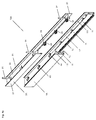
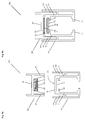
- Fig. 1a shows a sliding door system according to the invention with a parking space 7, into which a rail device 10A according to the invention is guided, which comprises a mounting rail 2A and a running rail 1A releasably connected thereto.
- the front piece of the running rail 1A is cut away slightly outside the parking space 7, so that the guided in the running rail drives 63 are visible, which are connected via door fittings 61 with a sliding door 6.
- the parking space 7 is bounded on both sides by room walls 71, 72, which were permanently installed after assembly of the mounting rail 2A and only with great effort are solvable.
- One manual intervention in the space opening 70 of the parking space 7 is no longer possible after the installation of the room walls 71, 72.
- the mounting rail 2A was installed at the desired height in horizontal alignment by means of mounting screws 91 on the ceiling of the room.
- the drives 63 and optionally a buffer device were inserted into the slide rail 1A, which was connected in sequence by inventive coupling devices with the mounting rail 2A.
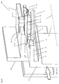
- Fig. 1b shows by way of example that the sliding door 6 is made of wood and provided at the upper corners with recesses 60, in each of which a door fitting 61 is inserted, which comprises a fitting rail 611 and a fitting block 612 inserted therein.
- the fitting block 612 is connected by a threaded rod 62 with the associated drive 63, the wheels 631 can roll on both sides in each case on a rail foot 13 of the running rail 1A in the running rail 1A.
- the drives 63 and the sliding door 6 are therefore displaceable along a running axis x and can be retracted into the parking space 7.
- the slide rail 1A has been partially cut away to show the drive 63 and the door fitting 61.
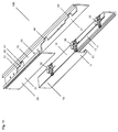
- Fig. 1c shows the out of the sliding door system of Fig. 1a taken rail device 10A, the front quarter was cut away in order to fully show the coupling devices that have connected to the mounting rail 2A coupling heads 3A and provided in the rail 1A coupling openings 4A.
- the coupling heads 3A that can be anchored in the coupling holes 4A will be described in detail below.
- the running rail 1A has a downwardly open U-profile with a central piece 12, which is connected on both sides with side pieces 11, each forming an L-profile with oppositely directed mod Suite 13.
- the side pieces 11 are also each connected by web elements with a flange plate 111 extending parallel thereto.
- the mounting rail 2A has an H-profile with a central piece 22, on both sides of the side pieces 21 are provided.
- the distance between the side pieces 21 of the mounting rail 2A is greater than the distance between the side pieces 11 of the rail 1A, but smaller than the distance between the flange plates 111 of the rail 1A.
- a coupling space 110 is formed between each flange plate 111 and the associated side piece 11, in which the associated side piece 21 of the mounting rail 2A can be inserted.
- the flange plates 111 project beyond the center piece 12 of the track rail 1A and thereby facilitate the coupling to the installed mounting rail 2A.
- the coupling openings 4A open into a coupling channel 15, which is partially bounded by the center piece 12 of the track rail 1A and two channel strips 16 which are aligned at the same height each with one of the side pieces 11 are connected. Between the channel strips 16, a space is kept open, which allows to engage with a tool in the coupling channel 15.
- the coupling head 3A is preferably held against rotation in an opening 28, e.g. screwed, caulked, welded or potted.
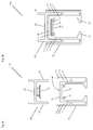
- Fig. 2b shows the rail device 10A of Fig. 1c after the connection of the rail 1A with the mounting rail 2A.
- the coupling plate 32 of the coupling head 3A was placed in the Coupling channel 15 is inserted and the center piece 12 of the track rail 1A is held between the side pieces 21 of the mounting rail 2A.
- the running rail 1A is therefore displaceable only parallel to the running axis x or parallel to the longitudinal axis of the rail device 10A. This facilitates the operation of coupling and decoupling the track rail 1A from the coupling heads 3A of the mounting rail 2A.
- Fig. 3a shows one of the coupling heads 3A of Fig. 1c
- Fig. 3b shows the coupling head 3A of Fig. 3a cut along the line AA
- Fig. 3c shows the coupling head 3A of Fig. 3a from underneath.
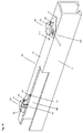
- Fig. 4 shows a part of the rail device 10A of Fig. 1c in a spatial representation with a section through the longitudinal axis of the mounting rail 2A.
- the coupling head 3A has a coupling neck 31 which includes a connecting piece 311 and a spacer 312.
- the connecting piece 311 which has a smaller diameter than the spacer 312, is formed as an octagon and serves to pass through a correspondingly formed octagonal opening 28 in the middle piece 22 of the mounting rail 2A.
- the top of the spacer 312 forms a flange ring which bears against the underside of the center piece 22.
- the upper end portion 310 of the connecting piece 311 projects in succession from the octagonal opening 28 (see also FIG Fig.
- the coupling neck 31 is followed by a round coupling plate 32 intended for insertion into the coupling channel 15 (see FIG Fig. 4).
- Fig. 3b shows that an axial Bore passes through the entire coupling head 3A, which can be manufactured with an internal thread.
- Fig. 4 shows the coupling opening 4A, which is provided in the center piece 12 of the track rail 1A and which includes a larger first opening portion 41 and a smaller second opening portion 42.
- the larger opening part 41 is adapted to the size of the coupling plate 32, which can be inserted at this point through the coupling opening 4A into the coupling channel 15. Subsequently, the running rail 1A can be moved relative to the mounting rail 2A and thereby anchored.
- the spacer 312 is preferably received by the second opening part 42 without play.
- the coupling plate 32 is held below the second opening part 42, the adjacent edges of which form a retaining flange.
- the guide rail 1A is therefore connected to the mounting rail 2A and can only be released again by the first opening part 41 is moved back over the coupling plate 32.
- a bolt or another fixing screw 91 can be performed in to lock the anchored running rail 1A relative to the mounting rail 2A.
- the rail 1A is held without play after anchoring to the coupling head 3A, preferably one or more elastic elements, preferably spring elements, such as leaf springs, are provided.
- At least one ramp is preferably provided.
- the at least one elastic element and / or the at least one ramp may be integrally connected to the coupling head 3A or integrally formed thereon.
- a buffer device is provided at which the at least one elastic element and / or the at least one ramp is provided.
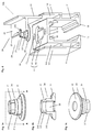
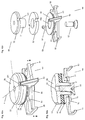
- Fig. 5a shows the coupling head 3A of Fig. 3a with a buffer device 5A connected thereto, which has spring elements 51 on both sides and a respective ramp 52 on the front and rear sides.
- Fig. 5b shows the coupling head 3A of Fig. 5a with the associated buffer device 5A from below.
- Fig. 6a shows the buffer device 5A of Fig. 5a from above and Fig. 6b shows the buffer device 5A of Fig. 6a from underneath.
- the buffer device 5A consists of a rectangular buffer plate 50, which has in the middle an opening 500, which serves to receive the coupling neck 31 of the coupling head 3A, as shown in FIG Fig. 5a is shown.
- the buffer plate 50 has downwardly directed elastic elements or spring elements, which are formed as leaf springs, which are held on both sides.
- the spring elements 51 were formed from the buffer plate 50 and are aligned parallel to each other. Alternatively, the spring elements 51 can be kept on only one side.
- On the underside of the buffer plate 50 is front and back each provided with a ramp 52, both of which, seen from below, rise against the opening 500 out.
- Fig. 5a It is shown that the spring elements 51 and the ramps 52 face the coupling plate 32 of the coupling head 3A so that they can cooperate with the center piece 12 of the running rail 1A inserted therein or with the edge of the center piece 12 enclosing the coupling opening 4A.
- Fig. 7 shows the rail device 10A of Fig. 4 with the buffer device 5A attached to the coupling head 3A Fig. 5a ,
- the buffer plate 50 abuts against the center piece 22 of the mounting rail 2A and the spring elements provided thereon 51 and ramps 52 face the center piece 12 of the track rail 1A.
- the mounting rail 2A is cut along the longitudinal axis so that the installed coupling head 3A with the buffering device 5A is visible.
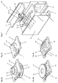
- Fig. 8a shows the rail device 10A of Fig. 7 with the rail 1A separated from the mounting rail 2A.
- Fig. 8b shows the rail device 10A of Fig. 8a after the coupling of the running rail 1A to the mounting rail 2A.
- the buffer plate 50 is held above the center piece 12 of the track rail 1A and presses this with the non-visible spring elements 51 backlash against the coupling plate 32 of the coupling head 3A, which is held by means of channel strips 16 within the coupling channel 15.
- Fig. 9 shows a spatial representation of a part of the rail device 10A of Fig. 8b with a section along the longitudinal axes of the track rail 1A and the mounting rail 2A. It can be seen that the octagonal connecting piece 311 of the coupling neck 31 in the octagonal opening 28 in the middle piece 22 of the mounting rail 2A is held against rotation. The upper end portion 310 of the connecting piece 311 of the coupling neck 31 protrudes beyond the center piece 22 of the mounting rail 2A and can be plastically deformed by caulking into a flange member.
- the buffer plate 50 of the buffer device 5A is located on the underside of the center piece 22 of the mounting rail 2A and presses with the spring elements 51 against the top of the center piece 12 of the rail 1A.
- the coupling plate 32 of the coupling head 3A has been inserted into the coupling channel 15 through the coupling hole 4A and is slightly above the channel strip 16.
- the ramps 52 are aligned parallel to the rail axes and prevent the coupling plate 32 from being under the edge of the middle 12 at the front or rear the running rail 1A can be driven.
- the coupling plate 32 is still below the first opening portion 41 and is by moving the guide rail 1A in the direction of the arrow shown below the second opening part 42 of the coupling opening 4A moved and anchored there. Through the opening 18 in the slide rail 1A, a locking element against the mounting rail 2A can be performed.
- Fig. 10a shows the rail device 10A of Fig. 9 with the coupling head 3A anchored in the second opening part 42 of the coupling hole 4A.
- the front-side ramp 52 of the buffer device 5 abuts the edge of the coupling opening 4A and prevents the coupling plate 32 in the direction of the axis X from getting under the center piece 12 of the track rail 1A.
- Fig. 10b shows the rail device 10A of Fig. 10a with the coupling head 3A displaced in the first opening part 41 of the coupling hole 4A.
- the rear ramp 52 abuts the edge of the coupling opening 4A and prevents the coupling plate 32 in the direction of the axis X can get under the centerpiece 12 of the slide rail 1A.
- Fig. 11 shows a rail device 10B according to the invention in a second preferred embodiment.
- the front quarter of the rail device 10B has been cut away to show the elements of the coupling devices that have coupling heads 3B connected to the track rail 1B that can be anchored in coupling holes 4B in the mounting rail 2B.
- the running rail 1B is designed simpler and has only a central piece 12 and on both sides provided thereon side pieces 11, which together with one foot piece 13 form an L-profile. On the middle piece 12, the coupling heads 3 B are arranged and held against rotation.
- the mounting rail 2B has a downwardly open U-profile with a central piece 22 in which the coupling openings 4B are provided. On both sides of the central piece 22 side pieces 21 are provided, whose mutual distance is greater than the mutual distance of the side pieces 11 of the running rail 1B.
- the running rail 1B can therefore be received in the U-profile of the mounting rail 2B, whereby the coupling of the running rail 1B is facilitated to the mounting rail 2B.
- the coupling openings 4B which are provided in the center piece 22 of the mounting rail 2B, correspond to the coupling openings 4A in the running rail 1A, for example according to Fig. 4 and also have a larger first opening portion 41 and a smaller second opening portion 42, which form approximately the shape of a keyhole.
- the first opening part 41 is, for example, approximately circular and the second opening parts 42 is elongate or at least approximately rectangular and preferably rounded.
- Fig. 12a shows one of the coupling heads 3B of Fig. 11 and a buffer device 5B connected thereto, which is likewise provided on the front side and the rear side with a ramp 52 and on both sides with spring elements 51.
- Fig. 12b shows the coupling head 3B and the buffer device 5B cut along the in FIG Fig. 12a shown section line BB.
- Fig. 12c shows the coupling head 3B and the buffer device 5B of FIG Fig. 12a in exploded view.
- the ramps 52 connected to the buffer device 5B prevent, as in the embodiment of FIG Fig. 10b in that the coupling plate 32 of the coupling head 3B can be mounted in the direction of the running axis X on the center piece 22 of the mounting rail 2B during the disassembly of the running rail 1B.
- the ramp 52 serves to hold the coupling head 3B against rotation.
- the buffer device 5B on both sides of holding elements 55 which grip the center piece 12 of the track rail 1B on both sides and thereby hold the buffer device 5B and the ramps 52 rotatably.
- the ramps 52 each protrude into a retaining groove 321 in the coupling plate 32 of the coupling head 3B, whereby the coupling head 3B is fixedly coupled to the running rail 1B and held rotatably.
- Fig. 12a and Fig. 12b show that the spring elements 51 are integrated into the buffer plate 50 and slightly curved against the coupling plate 32.
- Fig. 12b shows that between the coupling plate 32 of the coupling head 3B and a support plate 58 of the buffer device 5B optionally an elastic damping element 59 is provided which is annular and made of a resilient plastic material.
- the support plate 58, the damping element 59 and the coupling plate 32 form a unit and can be guided out of the unit through an associated coupling opening 4B in the centerpiece 22 of the mounting rail 2B and anchored and as shown in FIG Fig. 13 is shown.
- the guided through an opening 500 in the damping element 59 and in the support plate 58 coupling neck 31 has an internal thread into which a mounting screw 93 is screwed.
- the mounting screw 93 By means of the mounting screw 93, the coupling head 3B and the buffer device 5B are bolted to the center piece 12 of the track rail 1B.
- Fig. 13a shows the rail device 10B of Fig. 11 with the rail 1B separated from the mounting rail 2B, which is connected by the mounting screw 93 to the coupling head 3B and the buffer device 5B.
- Fig. 13b shows the rail device 10A of Fig. 13a after the coupling of the running rail 1B to the mounting rail 2B.
- the track rail 1B was lifted and, after the insertion of the coupling head 3B, shifted parallel to the barrel axis x through the first opening portion 41 of the coupling hole 4B, thereby guiding and anchoring the coupling neck 31 of the coupling head 3B into the second hole portion 42 of the coupling hole 4B.
- the elastic members 51 (not visible) abut the underside of the center piece 22 of the mounting rail 2B and at the top thereof, via the second opening portions 42, the coupling unit is held by the support plate 58, the damping member 59 and the coupling plate 32 is formed.
- the coupling plate 32 which is screwed to the center piece 12 of the track rail 1B is therefore separated by the elastic member 59 of the support plate 58, which rests against the center piece 22 of the mounting rail 2B.
- the mounting rail 2B is therefore elastically held from above by the damping element 59 and from below by the spring elements 51 and decoupled from the running rail 1B. Running noises caused by the drives 63 when the sliding door 6 is displaced are not transmitted to the mounting rail 2B and the building by the running rail 1B.
- Fig. 14 shows the running rail 1B of Fig. 11 with two coupling devices 3B installed on it, each provided with a modified buffer device 5B *.
- the buffer device 5B * again has a buffer spring 51 and a buffer ramp 52, which serve the described purposes.
- only one holding element 55 is provided, which is held in the form of a mandrel in an opening 121 in the middle piece 12 of the running rail 1B. Holding elements, which project beyond the running rail 1B laterally, can be avoided.
Landscapes
- Engineering & Computer Science (AREA)
- Mechanical Engineering (AREA)
- Civil Engineering (AREA)
- Structural Engineering (AREA)
- Support Devices For Sliding Doors (AREA)
Priority Applications (12)
| Application Number | Priority Date | Filing Date | Title |
|---|---|---|---|
| EP16166287.9A EP3235983A1 (de) | 2016-04-20 | 2016-04-20 | Schiebetüranlage und schienenvorrichtung |
| US16/090,355 US10724281B2 (en) | 2016-04-20 | 2017-04-06 | Sliding door system |
| ES17716200T ES2870525T3 (es) | 2016-04-20 | 2017-04-06 | Instalación de puerta corredera |
| SG11201808433YA SG11201808433YA (en) | 2016-04-20 | 2017-04-06 | Sliding-door system |
| JP2018551302A JP7113512B2 (ja) | 2016-04-20 | 2017-04-06 | 引き戸装置 |
| NZ746656A NZ746656B2 (en) | 2016-04-20 | 2017-04-06 | Sliding-door system |
| CA3019639A CA3019639C (en) | 2016-04-20 | 2017-04-06 | Sliding door system |
| CN201780024619.8A CN109072648B (zh) | 2016-04-20 | 2017-04-06 | 滑动门系统 |
| EP17716200.5A EP3445935B1 (de) | 2016-04-20 | 2017-04-06 | Schiebetüranlage |
| PCT/EP2017/058248 WO2017182286A1 (de) | 2016-04-20 | 2017-04-06 | Schiebetüranlage |
| AU2017253848A AU2017253848B2 (en) | 2016-04-20 | 2017-04-06 | Sliding-door system |
| TW106113130A TWI717499B (zh) | 2016-04-20 | 2017-04-19 | 滑動門系統 |
Applications Claiming Priority (1)
| Application Number | Priority Date | Filing Date | Title |
|---|---|---|---|
| EP16166287.9A EP3235983A1 (de) | 2016-04-20 | 2016-04-20 | Schiebetüranlage und schienenvorrichtung |
Publications (1)
| Publication Number | Publication Date |
|---|---|
| EP3235983A1 true EP3235983A1 (de) | 2017-10-25 |
Family
ID=55802275
Family Applications (2)
| Application Number | Title | Priority Date | Filing Date |
|---|---|---|---|
| EP16166287.9A Withdrawn EP3235983A1 (de) | 2016-04-20 | 2016-04-20 | Schiebetüranlage und schienenvorrichtung |
| EP17716200.5A Active EP3445935B1 (de) | 2016-04-20 | 2017-04-06 | Schiebetüranlage |
Family Applications After (1)
| Application Number | Title | Priority Date | Filing Date |
|---|---|---|---|
| EP17716200.5A Active EP3445935B1 (de) | 2016-04-20 | 2017-04-06 | Schiebetüranlage |
Country Status (10)
| Country | Link |
|---|---|
| US (1) | US10724281B2 (enExample) |
| EP (2) | EP3235983A1 (enExample) |
| JP (1) | JP7113512B2 (enExample) |
| CN (1) | CN109072648B (enExample) |
| AU (1) | AU2017253848B2 (enExample) |
| CA (1) | CA3019639C (enExample) |
| ES (1) | ES2870525T3 (enExample) |
| SG (1) | SG11201808433YA (enExample) |
| TW (1) | TWI717499B (enExample) |
| WO (1) | WO2017182286A1 (enExample) |
Cited By (1)
| Publication number | Priority date | Publication date | Assignee | Title |
|---|---|---|---|---|
| WO2020058157A1 (de) | 2018-09-18 | 2020-03-26 | Cimba Gmbh | Montageanordnung für eine laufschiene |
Families Citing this family (6)
| Publication number | Priority date | Publication date | Assignee | Title |
|---|---|---|---|---|
| USD936459S1 (en) * | 2019-10-14 | 2021-11-23 | Dirtt Environmental Solutions Ltd. | Door and ceiling frame component |
| USD974149S1 (en) * | 2019-10-16 | 2023-01-03 | Dirtt Environmental Solutions Ltd. | Ceiling hanger |
| DE102021201082A1 (de) | 2021-02-05 | 2022-08-11 | Buchele Gmbh | Verschlusseinrichtung zum Verschließen von Gebäudeöffnungen |
| DE202021004263U1 (de) | 2021-04-28 | 2023-05-08 | Hawa Sliding Solutions Ag | Verschiebevorrichtung für eine Schiebetür, Anordnung und Antriebsvorrichtung |
| EP4083363A1 (de) | 2021-04-28 | 2022-11-02 | Hawa Sliding Solutions AG | Verschiebevorrichtung für eine schiebetür, anordnung und antriebsvorrichtung |
| ES2958558B2 (es) * | 2022-07-15 | 2024-06-20 | Kriket Armazones S L | Sistema de montaje y desmontaje de guias de puertas correderas |
Citations (4)
| Publication number | Priority date | Publication date | Assignee | Title |
|---|---|---|---|---|
| US1945332A (en) * | 1931-05-25 | 1934-01-30 | Stanley Works | Track support |
| DE10012511A1 (de) * | 1999-04-14 | 2000-10-19 | Dana Tuerenindustrie | Tür, insbesondere Schiebetür |
| US6647590B2 (en) | 2000-10-13 | 2003-11-18 | Hawa Ac | Fixing device for a rail |
| DE202015105569U1 (de) * | 2014-10-22 | 2015-12-10 | Terno Scorrevoli S.R.L. | In einem Gehäuse integrierbare Vorrichtung für Schiebetüren |
Family Cites Families (16)
| Publication number | Priority date | Publication date | Assignee | Title |
|---|---|---|---|---|
| US3469892A (en) * | 1968-06-03 | 1969-09-30 | Watsco Inc | Shielded-bearing roller for suspension devices |
| DE29908332U1 (de) * | 1999-05-07 | 1999-10-28 | Hermann Francksen Nachf. GmbH & Co. KG, 28719 Bremen | Aufhängevorrichtung für eine Schiebetür |
| US6336247B1 (en) * | 2000-05-08 | 2002-01-08 | Frank Schnoor | Screen door hanger assembly |
| JP3741058B2 (ja) | 2002-02-22 | 2006-02-01 | 文化シヤッター株式会社 | 取付構造 |
| ATE373762T1 (de) * | 2003-07-03 | 2007-10-15 | Home Decor Holding Company | Schiebetür |
| US7712258B2 (en) * | 2004-04-22 | 2010-05-11 | K. Bradley Ewing | Suspension and sill system for sliding members |
| DE202004012852U1 (de) | 2004-08-17 | 2004-10-14 | Hespe & Woelm Gmbh & Co. Kg | Aufhängevorrichtung für Schiebetüren |
| USD558569S1 (en) * | 2006-05-24 | 2008-01-01 | Hydroscreen Pty Ltd | Sliding screen track |
| ES2564556T3 (es) * | 2006-10-19 | 2016-03-23 | Hawa Ag | Dispositivo con un mecanismo de rodadura para sujetar placas desplazables y elemento de separación |
| US7743557B2 (en) * | 2006-11-21 | 2010-06-29 | Good Credit Corporation | Sliding track coupling structure for sliding doors |
| EP2151538B8 (de) * | 2008-08-06 | 2017-05-03 | Hawa Sliding Solutions AG | Vorrichtung mit einem Laufwerk zum Halten von Platten, Laufwerk, Laufschiene und Trennelement |
| US8579006B2 (en) * | 2009-10-19 | 2013-11-12 | Adrian Mario Levin | Space divider system |
| EP2851496A1 (de) * | 2013-09-18 | 2015-03-25 | Hawa Ag | Justierbare Montagevorrichtung für ein Schiebeelement sowie Schiebevorrichtung |
| US10125528B2 (en) * | 2014-10-03 | 2018-11-13 | Zdzislaw Stanislaw Wypych | Easy glide storm door |
| US9487985B2 (en) * | 2015-05-07 | 2016-11-08 | Adam Conley | Movable closure system |
| CA2960208A1 (en) * | 2016-03-07 | 2017-09-07 | Jeld-Wen, Inc. | Sliding barn door hardware |
-
2016
- 2016-04-20 EP EP16166287.9A patent/EP3235983A1/de not_active Withdrawn
-
2017
- 2017-04-06 CA CA3019639A patent/CA3019639C/en active Active
- 2017-04-06 US US16/090,355 patent/US10724281B2/en active Active
- 2017-04-06 AU AU2017253848A patent/AU2017253848B2/en active Active
- 2017-04-06 WO PCT/EP2017/058248 patent/WO2017182286A1/de not_active Ceased
- 2017-04-06 CN CN201780024619.8A patent/CN109072648B/zh active Active
- 2017-04-06 JP JP2018551302A patent/JP7113512B2/ja active Active
- 2017-04-06 ES ES17716200T patent/ES2870525T3/es active Active
- 2017-04-06 SG SG11201808433YA patent/SG11201808433YA/en unknown
- 2017-04-06 EP EP17716200.5A patent/EP3445935B1/de active Active
- 2017-04-19 TW TW106113130A patent/TWI717499B/zh active
Patent Citations (4)
| Publication number | Priority date | Publication date | Assignee | Title |
|---|---|---|---|---|
| US1945332A (en) * | 1931-05-25 | 1934-01-30 | Stanley Works | Track support |
| DE10012511A1 (de) * | 1999-04-14 | 2000-10-19 | Dana Tuerenindustrie | Tür, insbesondere Schiebetür |
| US6647590B2 (en) | 2000-10-13 | 2003-11-18 | Hawa Ac | Fixing device for a rail |
| DE202015105569U1 (de) * | 2014-10-22 | 2015-12-10 | Terno Scorrevoli S.R.L. | In einem Gehäuse integrierbare Vorrichtung für Schiebetüren |
Cited By (2)
| Publication number | Priority date | Publication date | Assignee | Title |
|---|---|---|---|---|
| WO2020058157A1 (de) | 2018-09-18 | 2020-03-26 | Cimba Gmbh | Montageanordnung für eine laufschiene |
| CH715347A1 (de) * | 2018-09-18 | 2020-03-31 | Cimba Gmbh | Montageanordnung für eine Laufschiene zum Führen und Tragen einer Schiebetür. |
Also Published As
| Publication number | Publication date |
|---|---|
| EP3445935A1 (de) | 2019-02-27 |
| JP2019515160A (ja) | 2019-06-06 |
| AU2017253848B2 (en) | 2022-03-03 |
| TW201738452A (zh) | 2017-11-01 |
| NZ746656A (en) | 2021-01-29 |
| ES2870525T3 (es) | 2021-10-27 |
| US10724281B2 (en) | 2020-07-28 |
| TWI717499B (zh) | 2021-02-01 |
| AU2017253848A1 (en) | 2018-10-25 |
| EP3445935B1 (de) | 2021-02-24 |
| CA3019639A1 (en) | 2017-10-26 |
| JP7113512B2 (ja) | 2022-08-05 |
| SG11201808433YA (en) | 2018-11-29 |
| CN109072648B (zh) | 2020-08-11 |
| WO2017182286A1 (de) | 2017-10-26 |
| CN109072648A (zh) | 2018-12-21 |
| US20190112854A1 (en) | 2019-04-18 |
| CA3019639C (en) | 2023-05-09 |
Similar Documents
| Publication | Publication Date | Title |
|---|---|---|
| EP3235983A1 (de) | Schiebetüranlage und schienenvorrichtung | |
| EP1197624B1 (de) | Befestigungsvorrichtung für eine Schiene | |
| DE69705662T2 (de) | Rollvorrichtung für Schiebetüren, Fenster oder ähnliches | |
| AT509796B1 (de) | Hohlprofil | |
| EP0562073A1 (de) | Feststell- und verriegelungseinheit. | |
| EP3486420A2 (de) | Vorrichtung zum positionieren eines fensters oder einer tür | |
| DE102012208482A1 (de) | Befestigungsvorrichtung | |
| EP2927409B1 (de) | Dichtungsanordnung für eine schiebetür | |
| EP3636844B1 (de) | Trockenbau-tragrahmen für eine schiebetür | |
| DE102006016045A1 (de) | Vorrichtung zur lösbaren Halterung von einem Flächenelement und deren Verwendung | |
| EP1439278A2 (de) | Dichtung, insbesondere Auflaufdichtung oder sich selbsttätig absenkende Bodendichtung für Türen mit einstellbarer Befestigung | |
| DE102004005422A1 (de) | Montagekonsole für Fenster oder dergleichen | |
| DE10336414A1 (de) | Ankersystem einer Betonwandschalung | |
| DE102021103756A1 (de) | Adapter zur Halterung von Fassadenelementen | |
| DE10315045A1 (de) | Verbindung von zwei Profilstäben und Absperrungskonstruktion mit derartigen Verbindungen | |
| DE102008006800B4 (de) | Führungsvorrichtung für einen Schiebeflügel | |
| EP1898041B1 (de) | Vorrichtung und Verfahren zum Befestigen von Aufsatzelementen auf bauseitigen Rahmensystemen | |
| DE3706236C2 (de) | Verbindungselement für zwei Tragteile | |
| AT402335B (de) | Justierdübelsystem zur einstellbaren verbindung zweier elemente miteinander sowie eine gewindehülse, eine verankerungshülse, ein verankerungselement und eine bohrhilfe für das justierdübelsystem | |
| EP2562330A1 (de) | Beschlagsystem | |
| DE102004054028A1 (de) | Vorrichtung zum Positionieren einer Tür | |
| DE102014202797B3 (de) | Distanzhalter | |
| DE29600891U1 (de) | Sicherungseinrichtung | |
| EP3696362B1 (de) | Vorrichtung zum abstützen von fenster- oder türelementen | |
| EP3168405A1 (de) | Rahmenkonstruktion für eine schiebetüre |
Legal Events
| Date | Code | Title | Description |
|---|---|---|---|
| PUAI | Public reference made under article 153(3) epc to a published international application that has entered the european phase |
Free format text: ORIGINAL CODE: 0009012 |
|
| STAA | Information on the status of an ep patent application or granted ep patent |
Free format text: STATUS: THE APPLICATION HAS BEEN PUBLISHED |
|
| AK | Designated contracting states |
Kind code of ref document: A1 Designated state(s): AL AT BE BG CH CY CZ DE DK EE ES FI FR GB GR HR HU IE IS IT LI LT LU LV MC MK MT NL NO PL PT RO RS SE SI SK SM TR |
|
| AX | Request for extension of the european patent |
Extension state: BA ME |
|
| STAA | Information on the status of an ep patent application or granted ep patent |
Free format text: STATUS: THE APPLICATION HAS BEEN WITHDRAWN |
|
| 17P | Request for examination filed |
Effective date: 20180425 |
|
| 18W | Application withdrawn |
Effective date: 20180428 |
|
| RBV | Designated contracting states (corrected) |
Designated state(s): AL AT BE BG CH CY CZ DE DK EE ES FI FR GB GR HR HU IE IS IT LI LT LU LV MC MK MT NL NO PL PT RO RS SE SI SK SM TR |