EP3233370B1 - System für modulare fahrzeugbaugruppe und verfahren - Google Patents
System für modulare fahrzeugbaugruppe und verfahren Download PDFInfo
- Publication number
- EP3233370B1 EP3233370B1 EP15823565.5A EP15823565A EP3233370B1 EP 3233370 B1 EP3233370 B1 EP 3233370B1 EP 15823565 A EP15823565 A EP 15823565A EP 3233370 B1 EP3233370 B1 EP 3233370B1
- Authority
- EP
- European Patent Office
- Prior art keywords
- assembly
- pallet
- frame
- modular
- equipment
- Prior art date
- Legal status (The legal status is an assumption and is not a legal conclusion. Google has not performed a legal analysis and makes no representation as to the accuracy of the status listed.)
- Active
Links
Images


Classifications
-
- B—PERFORMING OPERATIONS; TRANSPORTING
- B62—LAND VEHICLES FOR TRAVELLING OTHERWISE THAN ON RAILS
- B62D—MOTOR VEHICLES; TRAILERS
- B62D65/00—Designing, manufacturing, e.g. assembling, facilitating disassembly, or structurally modifying motor vehicles or trailers, not otherwise provided for
- B62D65/02—Joining sub-units or components to, or positioning sub-units or components with respect to, body shell or other sub-units or components
- B62D65/022—Transferring or handling sub-units or components, e.g. in work stations or between workstations and transportation systems
-
- B—PERFORMING OPERATIONS; TRANSPORTING
- B23—MACHINE TOOLS; METAL-WORKING NOT OTHERWISE PROVIDED FOR
- B23P—METAL-WORKING NOT OTHERWISE PROVIDED FOR; COMBINED OPERATIONS; UNIVERSAL MACHINE TOOLS
- B23P21/00—Machines for assembling a multiplicity of different parts to compose units, with or without preceding or subsequent working of such parts, e.g. with program control
- B23P21/004—Machines for assembling a multiplicity of different parts to compose units, with or without preceding or subsequent working of such parts, e.g. with program control the units passing two or more work-stations whilst being composed
-
- B—PERFORMING OPERATIONS; TRANSPORTING
- B23—MACHINE TOOLS; METAL-WORKING NOT OTHERWISE PROVIDED FOR
- B23K—SOLDERING OR UNSOLDERING; WELDING; CLADDING OR PLATING BY SOLDERING OR WELDING; CUTTING BY APPLYING HEAT LOCALLY, e.g. FLAME CUTTING; WORKING BY LASER BEAM
- B23K11/00—Resistance welding; Severing by resistance heating
- B23K11/10—Spot welding; Stitch welding
- B23K11/11—Spot welding
- B23K11/115—Spot welding by means of two electrodes placed opposite one another on both sides of the welded parts
-
- B—PERFORMING OPERATIONS; TRANSPORTING
- B23—MACHINE TOOLS; METAL-WORKING NOT OTHERWISE PROVIDED FOR
- B23K—SOLDERING OR UNSOLDERING; WELDING; CLADDING OR PLATING BY SOLDERING OR WELDING; CUTTING BY APPLYING HEAT LOCALLY, e.g. FLAME CUTTING; WORKING BY LASER BEAM
- B23K11/00—Resistance welding; Severing by resistance heating
- B23K11/30—Features relating to electrodes
- B23K11/3063—Electrode maintenance, e.g. cleaning, grinding
-
- B—PERFORMING OPERATIONS; TRANSPORTING
- B23—MACHINE TOOLS; METAL-WORKING NOT OTHERWISE PROVIDED FOR
- B23K—SOLDERING OR UNSOLDERING; WELDING; CLADDING OR PLATING BY SOLDERING OR WELDING; CUTTING BY APPLYING HEAT LOCALLY, e.g. FLAME CUTTING; WORKING BY LASER BEAM
- B23K37/00—Auxiliary devices or processes, not specially adapted for a procedure covered by only one of the other main groups of this subclass
- B23K37/04—Auxiliary devices or processes, not specially adapted for a procedure covered by only one of the other main groups of this subclass for holding or positioning work
- B23K37/047—Auxiliary devices or processes, not specially adapted for a procedure covered by only one of the other main groups of this subclass for holding or positioning work moving work to adjust its position between soldering, welding or cutting steps
-
- B—PERFORMING OPERATIONS; TRANSPORTING
- B62—LAND VEHICLES FOR TRAVELLING OTHERWISE THAN ON RAILS
- B62D—MOTOR VEHICLES; TRAILERS
- B62D65/00—Designing, manufacturing, e.g. assembling, facilitating disassembly, or structurally modifying motor vehicles or trailers, not otherwise provided for
- B62D65/02—Joining sub-units or components to, or positioning sub-units or components with respect to, body shell or other sub-units or components
-
- B—PERFORMING OPERATIONS; TRANSPORTING
- B23—MACHINE TOOLS; METAL-WORKING NOT OTHERWISE PROVIDED FOR
- B23K—SOLDERING OR UNSOLDERING; WELDING; CLADDING OR PLATING BY SOLDERING OR WELDING; CUTTING BY APPLYING HEAT LOCALLY, e.g. FLAME CUTTING; WORKING BY LASER BEAM
- B23K2101/00—Articles made by soldering, welding or cutting
- B23K2101/006—Vehicles
-
- B—PERFORMING OPERATIONS; TRANSPORTING
- B23—MACHINE TOOLS; METAL-WORKING NOT OTHERWISE PROVIDED FOR
- B23K—SOLDERING OR UNSOLDERING; WELDING; CLADDING OR PLATING BY SOLDERING OR WELDING; CUTTING BY APPLYING HEAT LOCALLY, e.g. FLAME CUTTING; WORKING BY LASER BEAM
- B23K2101/00—Articles made by soldering, welding or cutting
- B23K2101/04—Tubular or hollow articles
- B23K2101/06—Tubes
-
- B—PERFORMING OPERATIONS; TRANSPORTING
- B23—MACHINE TOOLS; METAL-WORKING NOT OTHERWISE PROVIDED FOR
- B23P—METAL-WORKING NOT OTHERWISE PROVIDED FOR; COMBINED OPERATIONS; UNIVERSAL MACHINE TOOLS
- B23P2700/00—Indexing scheme relating to the articles being treated, e.g. manufactured, repaired, assembled, connected or other operations covered in the subgroups
- B23P2700/50—Other automobile vehicle parts, i.e. manufactured in assembly lines
Definitions
- the invention generally pertains to the field of product and vehicle assembly.
- the bodies typically include a skeleton of sheet metal components that are welded together through resistance spot welding, seam welding and brazing techniques to form what are commonly called “body-in-white” (BIW) structures.
- BAW body-in-white
- assembly plants have strived to employ flexible build processes so that different vehicles and varying vehicle models including alternate vehicle bodies, can be built along the same assembly lines.
- the ability to quickly change over from building one type of body to another causes significant difficulty for facilities due to the limited amount of space around assembly lines and the time required to change over equipment and components that are specific to one vehicle body.
- Prior assembly systems have employed some modular vehicle assembly subsystems which provided advantages in new installations and accommodating batch and random vehicle builds where different vehicle models or types of vehicles could be built along the same assembly line with reduced changeover time.
- Prior assembly subsystems have employed modular robotic assembly stations or cells which could be placed end-to-end to accommodate a specified assembly line or series of operations.
- each assembly station or cell included a modular, precision-manufactured to close tolerances scaffold frame structure and could be selectively equipped with the necessary number of industrial, multi-axis robots and end effectors for a specified assembly operation. Details can be found in the above-referenced U.S. Patent Nos. 8,201,723 ; 8,869,370 ; 8,713,780 and U.S. Patent Application Publication 2012/0304446 .
- peripheral equipment used in vehicle assembly for example liquid sealant dispensing devices and fastener feeders, required to support the robot assembly operations at a particular assembly station are traditionally placed on the plant floor and separate conveying systems required to transfer the sealant or fasteners to the robots positioned in the assembly cell for use.
- liquid sealant dispensing devices and fastener feeders required to support the robot assembly operations at a particular assembly station are traditionally placed on the plant floor and separate conveying systems required to transfer the sealant or fasteners to the robots positioned in the assembly cell for use.
- much time and effort is traditionally needed to precisely locate and mount the robots in positional relation to the other robots and equipment in the assembly cell.
- a modular assembly system according to the preamble of claim 1 and a method for providing application equipment for use in assisting assembly operations according to the preamble of claim 14 are known from the above mentioned U.S. Patent No. 8,201,723 .
- Examples of the present invention include a modular vehicle assembly line having a plurality of assembly cells having modular systems and equipment which improves on the above complexities and disadvantages in prior assembly systems and methods.
- the present invention provides a system as detailed in claim 1 and a method as detailed in claim 14. Advantageous features are provided in the dependent claims.
- a modular application equipment (AE) support pallet device is selectively used to elevationally support and secure application equipment, for example liquid sealant storage tanks and distribution pumps, above the assembly line and assembly tools, for example robots.
- the modular pallet is selectively connected to the assembly cell frame directly adjacent to, or in close proximity to, the robot (or other assembly tools or equipment) using the specific application equipment and further provides a simple logistical path to convey the consumable material, sealant, fasteners etc. directly into the assembly cell and the robot for application.
- the modular pallet device can be pre-constructed and shipped to the application equipment supplier wherein the application equipment can be mounted and tested at the supplier prior to delivery and installation at the assembly plant.
- Power, data and material conveying cables and hoses for the mounted peripheral equipment can simply be connected to coordinating equipment at a system integrator's facility or directly at assembly plant for a "plug and play" device enabling efficient installation, connection and commission/testing at the assembly plant.
- a modular assembly tool (AT) platform or tray is provided to easily locate and secure required assembly tools and associated AE devices to the modular assembly cell infrastructure.
- a floor-level modular robot platform is provided.
- an industrial programmable robot, control cabinet and associated accessory devices are preinstalled on a modular AT platform or frame which coordinates with the existing modular assembly cell infrastructure.
- the modular support platform similarly allows the equipment to be pretested prior to arrival at the system integrator or assembly plant and provides quick and precise positioning with the existing modular assembly cell infrastructure.
- the simple, secure and precise positioning of the robot relative to the platform, and the platform relative to the assembly cell or station provides immediate, predictable and highly repeatable location of the robot to the other assembly cell equipment greatly reducing the time and effort to positionally orient, program, and calibrate the robot over traditional devices and methods.
- the exemplary modular AT platform further provides secure and predictable positioning of AE devices relative to the robot, for example weld tip dressers for spot welding gun end effectors connected to the robots, further adding to plug and play advantages on installation at the assembly plant as described above.
- the modular AE pallets and AT platforms having non-model specific or model-specific AE devices and assembly tools are simply "unplugged" from the non-model specific assembly structures and replaced with the new, refurbished and/or AE devices or assembly tool equipment for the new vehicle model that has been tested/commissioned prior to arrival at the assembly facility or line.
- a modular guard fence is used with one or more aspects of the modular assembly station and modular inventive aspects noted above and discussed below.
- the guard fence includes a frame that is cantilevered from the assembly frame and, may, but in a preferred aspect, does not require connection to an assembly plant floor which was expensive and time consuming in conventional safety fences and guards.
- the exemplary fence includes an upper position and a lower position allowing selective access to assembly tools in the assembly station.
- a front panel is positioned between the assembly tools and control cabinets and AE devices of an AT platform. This prevents unauthorized access to the assembly tools while allowing access to the control cabinets and selected AE devices while the assembly tools are in operation.
- a method of establishing and purchasing a vehicle (or other product) assembly line is presented.
- an assembly plant throughput is established and the number of individual assembly lines forming the complete assembly line is determined.
- the throughput for each assembly line is calculated to meet the overall throughput target.
- the required assembly line equipment and services are divided up into non-model specific infrastructure equipment and services that are non-vehicle model specific and vehicle model-specific systems.
- the non-model specific systems may include the modular frames, conveyors and AE pallets and AT platforms.
- the non-model specific equipment is singly sourced to a supplier or a minimal number of suppliers.
- the vehicle model-specific assembly equipment is competitively bid, preferably on an individual assembly line by assembly line basis, the supplier awarded the individual line or lines being responsible for meeting the individual line throughput specification.
- the method provides at least the advantages of simultaneous and parallel design activities for non-model specific and model specific equipment, immediate design release of the modular non-model specific technical details of the assembly lines, increased commission of the equipment at the suppliers and rapid installation and final commission at the assembly plant through connection of the modular assembly line components and application equipment mounted thereto. This results in compressed timing to design and install an assembly facility at lower cost and overall lowered business risk which is more evenly shared between the OEM and suppliers awarded portions of the business.
- FIG. 1-16 Examples of a modular vehicle assembly system and methods 10 are described below and illustrated in Figures 1-16 .
- the exemplary assembly devices and systems are described as useful in high quantity assembling automotive passenger vehicles, but there are other applications for manufacturing and assembling other vehicles and products known by those skilled in the art.
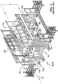
- a known vehicle assembly line for producing sheet metal skeletons of passenger vehicles known as "body-in-whites" (BIW) is shown on an assembly plant floor 14.
- a material entry area 20 a material loading and sequencing or staging area 30, and a plurality of assembly lines 38 (six shown in Figure 1 and identified as 40 - 45 as illustrated).
- Each assembly line 38 includes a vehicle-in-process travel path 60 running down each line 40-45.
- a pallet 106 generally supports a partially completed vehicle body (not shown).
- the pallet 106 is selectively moved along path 60 on a rail frame 110 having powered rollers to selectively move pallet 106 from assembly cell to assembly cell.
- An example of a powered pallet system is Comau LLC's VersaPallet brand system. Additional details can be found in U.S. Patent Nos. 6,564,440 and 6,966,427 .
- a useful overhead conveyor is Comau LLC's VersaRoll ® brand conveyor including powered rollers along an upper frame rail which engage and move a downward extending carriage along path 60 through the assembly cells 56. Additional details can be found in U.S. Patent Nos. 6,799,673 ; 6,564,440 and 6,719,122 .
- a useful system to monitor the position and stop the pallets 106 or overhead carriers 90 at desired positions in the assembly cells is Comau LLC's VersaCoder® system which uses a readable strip connected to the pallet/carriage and a reader. Further details can be found in U.S. Patent No. 7,108,189 .
- one or more exemplary assembly lines 40-45 may include a lower assembly path 60 and an upper return path 84 as generally shown.
- the assembly operations for example spot welding of sheet metal subassemblies and components, occur along the lower level in assembly cells 56 by programmable industrial, multi-axis robots 150 described further below.
- the upper return path of travel 84 may be used to return empty pallets or carriers to be restocked with components or fitted with a partially completed vehicle body for additional assembly.
- a lift (not shown) positioned at the end of an individual assembly line may raise, for example and empty carriage or partially completed vehicle body, from the lower path of travel 60 to the upper path of travel 84. Return of an empty transport carriage may occur if the partially assembled vehicle body is transferred to another carrier for continued assembly along downstream assembly lines.
- the above referenced lift may be positioned prior to the end of a line 40 - 45 to raise a partially completed vehicle to the upper path 84.
- an elevated transverse conveyor may move a partially completed vehicle body from an upper path 84 of one line 40 - 45 to an adjacent line for further build or assembly processes.
- a transverse tooling shuttle or conveyor device 112 may be used.
- the conveyor 112 allows for different tooling to accommodate different vehicle types to selectively move in and out of the assembly cell 56 along a path 116 that is substantially transverse to assembly path 60. Further details of assembly plant layout, assembly lines, tooling shuttles, component carts and carriers useful with the present invention can be found in U.S. Patent No. 8,201,723 ; 8,869,370 , 8,713,780 and U.S. Patent Application Publication 2012/0304446 .
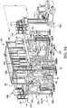
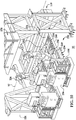
- the system includes a pair of scaffold-like frames 120.
- frame 120 includes a lower frame module 124 on each side of the assembly line path of travel 60 as generally shown (one assembly line described hereafter for convenience).
- the lower frame module 124 is manufactured and assembled to close dimensional tolerances and rigidly and removable secured to the plant floor 14 through threaded studs connected to mounting plates secured to the floor 14, typically concrete.
- the lower frame modules 124 are precisely spaced laterally from a predetermined and known centerline of the assembly line 60 in the assembly facility. The longitudinal position of the lower frame 124 along the assembly line is also determined through known 3-dimensional coordinate reference positions in the assembly facility. These positions may be defined using a large template or jig using the assembly centerline.
- an assembly cell reference center point 260 for the assembly station is determined as best seen in Fig. 12 .
- the predetermined reference point 260 provides an accurate and known location in the X, Y and Z dimensional coordinates from which other modular assembly system equipment for example the frames 120 are located from to support precision assembly operations along the assembly line.
- the lower frames 124 include an entrance point, for example the leading frame portion upstream, and an exit point, for example the trailing or furthest portion of frame 120 downstream.
- the lower frames 124 are precisely positioned longitudinally along path 60 from the known center or reference point 260 to provide a structurally rigid and dimensionally precise foundation for locating upper frames 130.
- the precision mounting location of the lower frames 124 along path 60 and precision mounting locations for the robots 150 connected to the frame 120 relative to the known reference point 260 of the assembly cell 56 provide accurate, precise and predictable orientation of the robots 150 for programming the movements of the robots 150 assigned functions in the assembly cell 56.
- the lower frames 124 are non-model specific.
- lower frames 124 are standard or generic and do not depend on which type of vehicle or vehicle body (or other product) will be built.
- the exemplary lower frames 124 are designed to handle or accommodate the building of substantially all passenger vehicles.
- the lower frames would be standard or non-model specific for other products that may have options or variations that can be ordered by customers.
- Each upper frame 130 is preferably precisely fabricated to small or close tolerances and mounted atop a respective lower frame 124 as generally shown (one described hereafter for convenience).
- Upper frame 130 includes vertical legs and an elevated floor 136 longitudinally extending along and parallel to path 60 forming a rigid scaffold-like assembly frame.
- Floor 136 is of a width 140 which is preferably about 1524 mm (60 inches). Other widths 140 and dimensions of upper frame 124 suitable for the application and known by those skilled in the art may be used.
- Precision-machined mounting surfaces (not shown) provide mounting points for assembly tools, for example programmable robots, although other assembly equipment and/or tools may be used.
- preferably three inverted multi-axis industrial robots 150 attach to the underside of floor 136 and extend down below floor 136 as generally shown.
- the upper frame 130 precision mounting surfaces accurately and precisely position the robots 150 relative to the upper 130 and lower 124 frames and assembly cell center point 260 providing a high level of dimensional and locational predictability and repeatability in the initial installed position and orientation of robots 150 with respect to the assembly cell for programing and operation.
- precision located mounting holes are provided in the upper frames 130 to accept modular robot mounting plates (not shown).
- the mounting plates for example, can be connected to the robots at the integrator's (i.e. vendor/supplier) facility with easy and precise connection to the upper frames 130 when installed in the assembly plant.
- tapered locating pins may be installed on the upper portions of the lower frame 124 and coordinate with apertures or other details in the mating upper frame 130.
- the tapered locating pins may be used to guide and position the upper frame 130 into 3-dimensional X, Y and Z precision location relative to the lower frame 124 and then secured in place with large bolts, other fasteners or other securing methods known by those skilled in the art.
- Lower 124 and upper 130 frames are preferably made from welded steel elements although other materials known by those skilled in the art may be used. It is understood that lower 124 and upper 130 frames may take other sizes, shapes and configurations than that shown consistent with the above description as known by those skilled in the art.
- each robot 150 is preferably housed in control cabinets 160 secured to upper frame floor 136 as generally shown.
- Other positions of the cabinets 160 suitable for the application and number of robots 150 (or other assembly tools and equipment) for a particular assembly cell 56 known by those skilled in the art may be used.
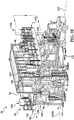
- AE pallet 170 includes a mounting surface or top 174 having a width 176 and vertical joists or supports 180 (three shown per pallet) as generally shown.
- AE pallets 170 may include a bottom 182 forming a rectangular pallet-like structure.
- AE pallet may further include a back panel (not shown) and a front panel (not shown).
- mounting surface 174 is shown as a top or upper surface, it is understood other mounting surfaces, configurations and orientations known by those skilled in the art may be used.
- mounting surface 174 is a rigid panel having a plurality of through holes or slots, mounting bosses, weld nuts and/or other features for mounting application equipment (AE) 190 suitable for the assembly operations in the assembly cell 56 and most preferably for a particular assembly tool, for example a robot 150.
- mounting surface 174 can be a rigid steel plate with holes positioned in a 100 millimeter grid pattern for ease of positioning and securing all types of AE devices 190.
- three (3) inverted robots 150 are connected to upper frame 130
- three (3) AE pallets 170 are preferably used providing the respective AE device 190 needed to support the respective robot 150 assigned an assembly task. As seen in Fig.
- AE devices 190 three (3) different forms of AE devices 190 are illustrated.
- a fluid storage and dispensing system 194 is secured to top 174 as generally shown.
- Consumable fluid materials such as sealants, adhesives, coolants and lubricants are common in vehicle body assembly lines.
- coolant or lubrication fluids such as water are considered consumable materials for purposes of the disclosure.
- the far right AE device 170 has a consumable materials fastener feeder 198 connected thereto.
- Such fastener feeders may include consumable rivets, weld studs, weld nuts, screws and other fasteners common to vehicle body operations known by those skilled in the art.
- the far left AE support 170 includes a third application equipment, for example a welding controller for a resistance spot welding of aluminum application.
- Other AE devices 190 needed to support common vehicle body (or other product) assembly operations may include equipment necessary to support welding operations including, but not limited to, resistance spot, seam, laser, brazing, piercing and clinching operations.
- Examples of consumables for seam or brazing operations may include welding wire or electrodes that are selectively fed by a feeder to the assembly tool in the assembly station as further described below. It is understood herein that reference of supply of consumable or other materials from the AE devices to the assembly tool, for example a robot, also includes the supply to any end effector or other tool connected to the assembly tool. Other AE devices 190, and consumable materials used thereby, known by those skilled in the art may be packaged and secured to a respective AE pallet 170. Although described as useful with robots 150, it is understood that AE devices 190 can be used with other assembly tools and equipment needed to support assembly and manufacturing line processes and operations known by those skilled in the art.
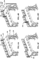
- AE pallet 170 includes hooks 188 rigidly mounted to two or more vertical supports 180 as best seen in Fig. 6 .
- Exemplary hooks 188 laterally extend outward from vertical supports 180 and engage cooperating structures, for example slots 144 in a laterally outward facing surface 142 of upper frame 130 forming a localized lateral continuation of floor 136 as best seen in Fig. 7 .
- the coordinating mounting holes may be in the floor 136.
- AE pallet 170 is mounted atop upper frame floor 136 through mechanical fasteners as generally shown (space shown between 170 and 136 for ease of illustration).
- the width 140 of upper frame 130 may be increased (not shown) to accommodate the width 176 of AE pallet 170 while allowing adequate space for walkway 210 as described below.
- Other structures, orientations and fastening methods for removably mounting AE pallets 170 to upper frame 130 known by those skilled in the art may be used.
- AE pallet 170 is configured to form a pallet-like support structure for any AE device 190 to provide consumable materials, other materials, or services (for example electrical power, fluids or data) to the assembly line, preferably adjacent exemplary industrial robots 150.
- pallet 170 width 176 is approximately 914 mm (36 inches).
- the combined widths 140 of upper frame 130 floor 136 and width 176 of AE support are less than 2438 mm (96 inches) which is the standard width of a commercial boxcar shipping container.
- Other widths 140 of floor 136 and AE pallet 170 may be used to suit the particular application and assembly line environment. It is also in the disclosure that the widths can comprise two or more pieces for ease of shipping and then assembled at the system integrator or on site at the assembly facility.
- the exemplary pallet 170 is preferably configured, oriented and adapted to be lifted, carried and elevated by a forklift common in assembly plants.
- the modular AE pallets 170 are shipped "empty" to a supplier/vendor responsible for providing AE devices 190 to support assembly operations in one or more assembly cells 56 along one or more assembly lines 38-45.
- the vendor can design and package the AE devices 190 in the space provided by the modular pallet170, securely mount the AE device 190 to the top 174 and fully test and commission the operation of the equipment at the supplier's facility thereby providing tested and ready to use equipment on installation at the assembly plant.
- AE devices 190 may be mounted in other orientations with respect to pallet 170, for example connected to the underside of top surface and extending downward. Other mounting and orientations of AE devices 190 to pallets 170 known by those skilled in the art may be used.
- AE pallets 170 provides for several configurations depending on the assembly operations for a particular assembly station 56.
- a safety rail 146 normally installed to upper frame surface 142 or floor 136, is simply disconnected from upper frame floor 136 and mounted to rail connection points (not shown) on AE pallet 170 as generally shown.
- Securing AE pallets 170 and reconfiguring the AE devices 190 for assembly cell 56 can be done in a matter of minutes versus hours or days with conventional assembly systems.
- Conduit 200 includes one or more of cables, wiring harnesses and/or pipes, 202, 204 and 205 positioned between the AE devices 190 and the assembly cell are shown.
- conduit 200 may be a single or multiple conduits/cables/pipes 202, 204 and 205, used to route, for example, an electrical and/or data cables 202 for the transfer of electrical power and information data from the control cabinets 160 to supply the necessary electricity and data to the AE devices 190 to, for example, power a fluid distribution pump 194 to supply pressurized adhesive or sealer to robot 150 or other assembly tools or cell equipment.
- conduit 200 may be a single or multiple conduits/cables/pipes 202, 204 and 205, used to route, for example, an electrical and/or data cables 202 for the transfer of electrical power and information data from the control cabinets 160 to supply the necessary electricity and data to the AE devices 190 to, for example, power a fluid distribution pump 194 to supply pressurized adhesive or sealer to robot 150 or other assembly tools or cell
- conduit 200 may include a cable 204connected between the AE device 190 and the assembly tool exemplary robot 150 to provide consumable materials and other materials, data and services to the assembly tool robot in order for the robot to perform the predetermined and preprogrammed assembly tasks in coordination with the application equipment 190 in the assembly cell.
- conduit 200 may include a pipe 205 is connected to the AE device 190 and routed through or around the AE pallet 170, under upper frame 130, through or around robot wrist 152 to the end effector 156 for the routing of consumable materials to assist assembly operations for that particular assembly tool. For example, it is common along vehicle body assembly lines to install adhesives, sealants and weld studs to the partially completed vehicle body in assembly cell 56. Where a robot 150 is tasked with welding operations, the fluid dispensing system 194 may provide water or other fluids to cool the equipment for continuous operation.
- consumable materials for example rivets, screws, or weld studs
- Additional AE devices may be installed on the same AE pallet to further support, for example, a seam welding robot through feeding of consumable welding electrode through conduit 200 to support the welding operation.
- conduit 200 could be a pipe or casing separate from the individual cables/wires and pipes described above, or may simple be the cables/wires and pipes themselves.
- conduit 200 may include hoses or pipes for the transport of fasteners into the assembly cell.
- AE pallet 170 includes one or larger routing apertures (not shown) in top 174 and open face 178 for the ease of routing conduit 200 laterally toward upper frame 130.
- the assigned robot 150 or other assembly cell tools would include the appropriate coordinating and reciprocal connectors so conduits 200 and/or 202, 204 and 205 can be rapidly connected for communication of consumable materials, data and other items on installation of the modular AE pallet 170 to upper frame 130 as described.
- Other communication lines, conduits and routing techniques and connections known by those skilled in the art may be used.
- the conduit 200 may simply be routed around the AE pallet floor versus through apertures in the floor as described.
- conduit 200 may come installed with the AE pallet and AE device as transferred into the assembly facility or may be largely, if not wholly installed in the assembly station.
- the AE device 190 may have a short conduit or simply connectors on the AE device 190 so it can be rapidly connected and placed in communication with the assembly cell control cabinet and/or the assembly tool in the manners described.
- I combination of conduits 200 is also contemplated.
- both the assembly station and AE device may have a conduit with coordinating connectors which are engaged on installation of the AE pallet to the frame.
- the AE pallet 170 comes "pre-wired" and includes coordinating connectors on the pallet 170.
- the pallet 170 may have common connectors or a bank of plugs wherein the AE device plugs into the pallet 170.
- wires/cables and pipes preinstalled in the assembly station are routed and plugged into another bank of connectors/plugs which place the AE device 190 in communication with the assembly tool and control cabinets in the manners described.
- Other structures and methods of connecting the AE pallet and AE device in communication with the assembly station known by those skilled in the art may be used.
- the entire first pallet 170 can be disconnected and replaced with a replacement first modular pallet 170 with a pre-installed and tested replacement first AE device 190 with minimal assembly line downtime and logistical disruption.
- This modularity and plug and play connectively will greatly reduce critical downtime of the assembly line for repairs, replacement and time consuming maintenance of application equipment 190.
- the modularity also is a major advantage for vehicle model and other product changeovers requiring reassignment of a robot 150 assembly operation or other assembly line tools/ equipment.
- a second AE pallet 170 with a second AE device 190 suitable for the new assembly tool or operation can be quickly mounted to upper frame 130 through a forklift or existing gantry crane and connected to the retasked or new assembly tool through conduit 200 as described above.
- the second AE pallet would be the same modular AE pallet 170 used with the first AE device, but having a different, second AE device 190 connected to it suitable for the alternate assembly operation by the assembly tool. It is contemplated that more than one type or form of modular AE pallet 170 may be used to accommodate the various AE devices 190 or assembly line operations.
- the elevation of the application equipment 190 further removes such equipment from traditional placement on plant floor 14 and routing of the communication or support lines up to the inverted robots 150 which typically required dedicated frames to support and route the lines, for example hoses and fastener conduits.
- the dimensional size of floor 136 and the placement of control cabinets 160 and application equipment 190 preferably provides for a walkway 210 along floor 136 longitudinally along upper frame 130. In one example, this is advantageous for access and maintenance of systems in the control cabinets 160 and AE devices 190 positioned thereon or connected thereto. Further, as the AE device 190 which provides consumable items such as adhesives and fasteners to the assembly cell, these consumable materials need to periodically be replenished. Walkway 210 provides a pathway for operators (see Fig. 8 ) to maneuver and restock these consumables for continuous assembly station operation. As an example shown in Figs.
- a drum of fluid can be raised by a forklift and installed atop floor 136.
- a dolly or cart can be used by an operator to move and replace an empty fluid storage container for a fluid dispenser 194. Where fasteners need to be replenished, an operator can manually carry a box of fasteners and load them in the application equipment hopper for future distribution to the robot 150 by the application equipment 190 and conduit 200 as described.
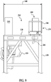
- Distribution deck 212 is used to assist in the supply or replenishment of consumables, for example, adhesives, sealants, fasteners and other materials that are used by the various AE devices 190 mounted on AE supports 170.
- deck 212 is positioned at one or both ends of an assembly line 40 - 45 ( Fig. 1 ) and has a platform which is preferably directly adjacent and at the same elevation as floor 136 of the upper frame 130 and in the exemplary AE pallet floor 174 shown in Figs. 4 , 7 and 8 .
- consumables for example 55 gallon drums of sealant 216 for use in fluid distribution device 194, would be raised up to platform 214 by a forklift or other device and deposited on the platform. Operators can manually, or through aid of a moving device, move by hand cart the consumables deposited on deck 212 along path 210 to the appropriate AE pallet 170 where the consumables are needed. This is very advantageous for continuous operation of the AE devices 190 and assembly station 56. The position of the AE devices 190, consumables 216 and workers above the assembly cell 56 for this work is very advantageous for plant logistics, efficiency and safety. Other methods of depositing the consumables 216 on platform 214 and movement along path 210 may be used as known by those skilled in the art.
- a distribution deck 212 would be provided at one end of each assembly line 40-45 adjacent to the material load and sequence area 30.
- distribution deck 212 may be continuous and span several or all assembly lines 40-45 or be individual to each line where consumables are needed to support assembly operations.
- the consumables 216 would travel the least distance from the material entry area 20 to the assembly line and thus further simplify assembly plant floor congestion and logistics.
- Other configurations and locations of distribution deck 212 known by those skilled in the art may be used without departing from the present disclosure. It is further understood that distribution deck 212 may serve other purposes than receipt of consumable materials as known by those skilled in the art.
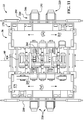
- an example of an aspect of system 10 includes modular assembly tool (AT) platforms or trays 220 to provide assembly tools or other assembly equipment, for example programmable multi-axis robots 226, additional AE devices 190 and associated accessories or devices used thereby.
- AT assembly tool
- modular robot platforms 220 are illustrated (two shown in Fig. 10 , four shown in Fig. 11 ) at floor level 14 of the assembly cell 56.
- a floor-positioned industrial multi-axis robot 226 having a principal axis of rotation 230 (shown in Fig. 13 ) is mounted to a base 236.
- base 236 includes a base plate having precision, most preferably equally spaced, mounting points or holes 240 for mounting the robot 226.
- the exemplary base plate is preferably mounted to frame rails 246 that extend laterally outward from assembly path 60 as generally shown. Rails 246 preferably also include precision positioned mounting points 250, for example holes, along the length of the rails.
- the exemplary base plate and rail mounting points provide predetermined, highly predictable and repeatable mounting points in the Z, Y and Z dimensional coordinates for the robot relative to the rails 246.
- rails 246 are rigidly connected to a continuous product conveyor or other equipment positioned along the assembly line or path 60 relative to the assembly station reference point 260 as best seen in Fig. 11 .
- Connection of the modular AT platform 220 including exemplary frame rails 246 can be made through use of rigid brackets 254 mounted in holes 252 as generally shown or other connection devices and configurations known by those skilled in the art.
- conveyor rail holes 252 are equally spaced apart and generated with close/small dimensional tolerances for accuracy and precision mounting of the AT platforms 220.
- Mounting points 252 may include other structures to securely connect AT platform 220 to the conveyor or other assembly station structure for the particular application.
- platform 220 base is shown including rails 246, it is understood that the frame or support structure can vary depending on the assembly tools and AE equipment and application.
- support 220 may include a pallet-like structure as 170 so the AT platform 220 can be transferred and moved to the line by a forklift.
- the exemplary base plate may include a heavy steel plate with a grid of equally spaced holes 100 millimeters (mm) for ease of mounting the assembly tools and AE devices.
- the plate may be supported by rails 246 or other structures known by those skilled in the art. It is understood other platform 220 constructions to positon and mount platform 220 to the conveyor or support structure 110 can be used as known by those skilled in the art.
- the exemplary precision base plates 236, rails 246 and mounting holes 240, 250 and 252 provide for accurate, precise and repeatable X, Y and Z coordinate dimensional positioning of the robot 226 relative to the known assembly cell center point 260 and other assembly station equipment thereby facilitating rapid placement, plug and play and programming of the exemplary robots 226 for assembly operations once installed at the assembly plant.
- AT platform 220 may be connected to mounting plates that are installed in the assembly plant floor in a similar manner to those described for mounting assembly station lower frames 124 described above and below for Fig. 15 .
- Modular AT platforms 220 may further include the necessary control cabinets 156 to power and communicate programs and data with the respective assembly tools and AE devices 190 installed on support 220.
- the assembly tools, AE devices 190 and control cabinets can be pre-installed on base plates 236 and/or frames/platforms 246 at the assembly tool or other supplier's facility and be fully commissioned/tested before shipment to the system integrator or directly to the assembly plant for installation.
- the AT platforms 220 can be pre-wired and cabled as necessary with a conduit 200 for plug and play installation and operation at the assembly facility as similarly described above.
- the AE devices 190 can supply consumables and other materials and functions to the assembly tools, for example robots 226, as described for AE pallets 170.
- the preferably self-contained, operational and initially tested/commissioned modular AT platforms 220 and equipment thereon can be transported to the assembly line, rapidly secured and connected to the existing assembly station equipment and control system in a plug and play manner as generally described for AE pallets 170 and AE devices 190. This greatly reduces the time and effort to locate, program and calibrate the assembly tool into the assembly station for rapid, small/close dimensional tolerance production operation.
- any control cabinets and AE devices required for AT platform 220 can be mounted to the base 236 or other structure described above or can be stand alone devices that are separately and independently positioned and secured in proximity to the AT platform assembly tool.
- an example of an AE device 190 can be automated weld tip dressers (not shown) precisely positioned on a larger base plate 236 or frame relative to the robot. For example, at scheduled intervals, the robots 226 can be programmed to run a maintenance cycle wherein the robots position the end effector spot weld gun weld tips in engagement with the weld tip dressers to condition the weld tips for optimum and continuous operation of the assembly cell.
- Other AE devices 190 discussed above, and methods of coordinating, integrating and connecting and connecting these devices with assembly tools known by those skilled in the art may be used.
- fence 270 includes a first frame 272 and a second frame 273 as generally shown.
- each frame 273 and 273 includes a vertical post 274, an upper support 276, an upper rail 278 and a lower rail 280.
- one or more front panels 286 extending along parallel to assembly path 60 and side panels connected between the upper 278 and lower 280 rails are used.
- each fence frame is rigidly mounted to and cantilevered from the assembly station lower 124 and upper 130 frames as generally shown.
- Front 286 and side 290 side panels can be made from steel, aluminum or other materials, for example transparent materials like polycarbonate, forming a grating or barrier to keep personnel and objects from unauthorized entry into the assembly station.
- Other materials, sizes, shapes and configurations of the panels and frames known by those skilled in the art may be used.
- the front panel 286 is slidingly mounted in guides 296 and connected to a retractor device 300.
- a retractor device 300 includes an electric motor 302 mounted to upper frame 130, a cable 304 and a stationary pulley 308 as generally shown.
- the retractor is selectively operable by an operator or control system (not shown) to raise the front panel from a first lower position 310 proximate floor 14 to a raised upper position 316.
- Upper position 316 is preferably of sufficient height such that operators and other equipment, for example forklifts, can enter assembly cell 56 and access and move assembly tools and other equipment to and from assembly cell 56 as necessary in the normal operation of the facility.
- the guides 296 are preferably positioned laterally outward from the assembly tool robots 226 and laterally inward from control cabinets 156 and AE devices 190 as generally shown. This provides access to the assembly tool controls and AE devices 190 to, for example replenish consumable materials provided to the assembly tools by the AE devices 190.
- Other positions of fence front and side panels known by those skilled in the art are within the present disclosure.
- the front panel 286 is normally positioned in the lower position 310 when the assembly station 56 is energized or in active assembly operations.
- retractor device 300 can be engaged manually or through signals received from a local or central controller (not shown), to raise front panel 286 to the upper position 316 allowing personnel and equipment easy access into the cell 56 without the need for disassembly or partial removal/relocation of traditional protective fences or guards.
- a local or central controller not shown
- retractor 300 can take other forms and features known by those skilled in the art. For example, front panels can be manually raised and locked into place with pins or other devices and then manually lowered to continue assembly operations.
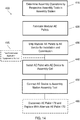
- a flow chart of an exemplary process 400 to build and install AE pallets 170 in an exemplary robot assembly tool application is shown.
- the exemplary process at step 410 it is determined the number and specific assembly operations that will be performed in one or more assembly stations 56, for example exemplary vehicle body assembly operations executed by industrial robots 150 with various end effectors for a variety of assembly operations.
- a plurality of modular, and preferably identical, AE pallets 170 are fabricated having the structural and spatial features described in the examples above in step 420.
- the modular AE pallets 170 are shipped "empty" in large quantities to a respective vendor for installation of an AE device (or devices) 190 by the vendor for a particular robot 150 or other assembly tools.
- the installed AE device 190 on the modular pallet 170 is pre-wired/pre-cabled with conduit 200 including power and data communication lines 206 appropriate for the assembly station, assembly tool and/or assembly operation and mated with coordinating connectors for attachment with connectors on the control cabinets, the robots 150, other assembly tools or other assembly cell equipment.
- the AE device 190 is then preferably tested/commission at the vendor or system integration to ensure proper operation before shipment to the assembly plant. In some AE devices 190, advanced testing and pre-programming of software can be performed at the vendor with minimal or no modifications and adjustments being necessary at the assembly plant for volume production.
- the modular AE pallet 170 and installed AE device 190 is shipped to an intermediary system integrator facility, or alternately directly to the assembly plant, and matched with the prefabricated assembly scaffold frame 120, conveyors, non-model specific equipment, for example pre-installed robots 150, and selected model-specific equipment assigned the assembly task supported by the application equipment 190.
- the pallet 170 may be elevated into position proximate upper frame 130 and floor 136 by a forklift or other lifting mechanism.
- the modular pallet 170 is then engaged to the upper frame 130 in the examples described, for example engagement of hooks 188 with coordinating slots 144 in upper frame 130.
- step 450 the application equipment conduit 200 is routed and the prewired or pre-cabled lines 202, 204, 205 and/or 206 are connected to the pre-wired or pre-cabled robot 150, control cabinets or other cell equipment for rapid install, communication and operation of the assembly cell 56.
- consumables 216 are transferred to and placed on upper frame(s) 130 through distribution decks 212 to supply the respective AE devices 190 with needed materials to support the predetermined assembly operations.
- the entire pallet 170 is preferably disconnected from the control cabinet, robots and upper frame 130 and quickly replaced with another pallet170 with replacement or alternate AE device(s) 190.
- the existing AE pallets 170 with AE device 190 is disconnected and swapped out with an alternate pallet 170 having the appropriate AE device 190 for the new assembly task.
- the process 400 may equally be applied to AT platforms 220, or the AE devices 190 used therewith as described.
- the modular AT platform 220 can be disconnected and replaced with a new or alternate assembly tool and AE devices 190 as required, and connected to the conveyor or other equipment as described above.
- the mounting points of the base 236, rails 246 and conveyor provide for rapid reconnection of a replacement AT platform 220 relative to the assembly station and/or assembly station reference point 260 thereby minimizing reprogramming or calibration of the new assembly tool.
- FIG. 15 an exemplary method 500 of assembling or installing a modular vehicle assembly system 10 is illustrated.
- system 10 infrastructure such as frames 120, conveyors or transports 48, assembly tools for example robots 150/226 and other unique tooling is assumed to be already complete, but understood can vary as known by those skilled in the art.
- the centerline of assembly line 60 is preferably determined.
- the centerline is determined from existing X, Y and Z dimensional coordinate reference points defined by the assembly plant.
- An assembly cell reference point 260 may be determined as described above.
- step 510 lower frame 124 mounting plates are secured to the assembly plant floor 14 in predetermined locations relative to the assembly line 60, assembly center line and/or assembly cell centerpoint 260 as generally described and illustrated.
- step 520 the lower frames 124 are removably secured to the mounting plates on both sides of the assembly line path 60.
- the attachment points where the lower frames attach to the floor mounting plates are preferably laterally spaced from the assembly line centerline and longitudinally positioned along the assembly line at predetermined locations.
- the lower frames 124 are mounted to the floor at predetermined locations which then the below conveyor is positioned and mounted with respect thereto.
- the assembly cell reference point 260 may then be established based on the installed frame and conveyor.
- step 530 the vehicle conveyor system along assembly path 60 is installed as well as any framing needed where a return conveyor along a return upper path 84 is installed.
- a transverse tooling conveyor 112 may be installed.
- the lower frames 124, and conveyors 50/52/90/110 defining respective assembly paths 60/78 and 84, tooling conveyor 112 (if an overhead conveyor system) and protective fences 280 are considered to be vehicle non-model specific equipment. In other words, these devices are preferably wholly standard and used for all vehicle models or other products to be assembled.
- the assembly station upper frame 130 is installed and secured atop the lower frame 124.
- the assembly tool industrial robots 150 and control cabinets 160 are pre-installed on the upper frame 130 as a unit by a vendor prior to delivery to the assembly cell and prior to securing it to lower frame 124.
- the upper frames 130 although may all be modular, identical and standard in construction, are shipped "empty" to a vendor for installation of model-specific equipment, for example preprogrammed assembly tool robots 150 and appropriate control cabinets 160.
- the vendor similar to that described for AE pallets 170 and AE devices 190, installs and commissions the assembly tools and/or model specific equipment on upper frame 130 (or as much as practically possible depending on the equipment and application) at the vendor or system integrator's facility prior to shipment to the assembly facility for installation into the assembly station 56 and final commission for production assembly.
- the robots 150 and control cabinets 160 may be installed following installation of the upper frame 130 onto the lower frame 124 in the assembly facility or in another sequence as known by those skilled in the art.
- exemplary step 550 the AE pallets 170 with preinstalled and commissioned vehicle/product model specific AE devices 190 are transported to the assembly facility and secured to upper frames 130, coordinated with the appropriate control cabinet, and electronically connected to the robot 150, end effector or other assembly cell tools and equipment as generally described above.
- the same or similar process would be carried out for any model specific modular AT platforms 220 for a pallet-style conveyor system ( Fig. 2 ) as generally described above.
- step 560 unique vehicle or product model specific tooling trays, tooling, fixtures and other equipment are delivered and installed to complete the operational assembly station equipment.
- any remaining protective fences 270 to accommodate the model specific equipment are installed and/or enabled. It is understood that depending on the assembly cell, part or all of the protective fence or fences 270 may be installed earlier as described or where appropriate in the cell assembly process.
- FIG. 16 another exemplary aspect is illustrated.
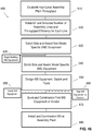
- business method or solution 600 for purchasing/sourcing, fabricating and installing equipment for a vehicle body or other product assembly line is illustrated.
- the exemplary process is particularly useful with the modular system 10 described above, but may be used with other assembly operations for other products. It is understood the method 600 can be used for products other than vehicle body assembly as known by those skilled in the art.
- step 610 establishes high level assembly plant parameters including plant size and target vehicle (or other product) throughput (vehicles/products per hour, shift, week and/or month or other periods or variables).
- step 620 the assembly plant is preferably simulated three-dimensionally through CAD-CAM or other simulation tools to establish the number of assembly lines and throughput and/or efficiency of each individual assembly line. It is understood this step could be done manually or through other conventional processes and mechanisms known by those skilled in the art.
- step 620 the assembly operations and equipment necessary for completing the assembly tasks are determined for each assembly line 40-45.
- the equipment is initially determined to be vehicle/product non-model specific or vehicle/product model specific.
- equipment is vehicle non-model specific if the equipment is useful in assembly regardless of which vehicle model or body style is being assembled.
- vehicle non-model specific and model specific for the described system 10 is:
- the non-model specific equipment is placed out for competitive bid contract and awarded to a single or minimum number of vendors.
- all vehicle non-model specific assembly equipment for all assembly lines may be sourced to one vendor.
- the non-model specific equipment is standard and/or modular and at least partially pre-designed. This reduces and minimizes prior processes which took months and months to largely, if not wholly, custom design the non-model specific infrastructure and equipment for every assembly plant.
- the process to bid and award happens far more quickly than the conventional process.
- fabrication can begin on the system 10 modular non-model specific infrastructure and equipment.
- step 640 based on the predetermined and preferably already designed modular, non-model specific equipment, the vehicle model specific assembly equipment is specified and competitively placed out for supply bid contract.
- the bids for the model specific equipment can go out much faster, possibly many months faster, as the non-model specific designs, or a great many portions thereof, are already complete.
- supply contracts for the model specific equipment for each assembly line 40 - 45, or combinations of assembly lines may be awarded to other integrators/vendors.
- the non-model specific equipment is already partially or wholly awarded and preferably fabrication already underway.
- each winning model specific vendor would be responsible for the required product throughput performance for the awarded lines. It is understood that steps 635 and 640 can occur simultaneously or even switched depending on how long the lead times are for effective management of the quotation process.
- step 650 the awarded model specific equipment is designed. During this period, fabrication of the awarded non-model specific in step 635 continues. Where appropriate, in step 655 installation of the completed non-model specific equipment can occur at the assembly facility for initial commission. Where non-model specific equipment is to be delivered to the model-specific vendor, for example empty upper frames 130, AE pallets 170 and AE platforms 220, these can be shipped to the model specific vendors in step 660.
- exemplary step 670 the model specific equipment is fabricated and commissioned/tested.
- AE pallets 170, AE supports 220 and necessary AE devices 190 are installed, wired and plumbed with the appropriate cables and harnesses and tested at the vendor's facility as generally described above.
- the tested vehicle model specific equipment arrives and is installed at a system integrator or directly at the assembly plant.
- the AE pallets 170 with installed AE devices 190 the AE pallets are lifted into positon and quickly secured to upper frame 130 as previously described.
- the conduit 200 which may include one or more of 202, 204, 205 and 206 are quickly and readily connected to the control cabinets, robot 150 (or other assembly tools or equipment) and coordinated with the equipment in the assembly station for rapid and already proven operability avoiding may problems and delays in conventional systems. This similarly occurs for modular AT platforms 220 as previously described.
- Other model-specific equipment is fabricated, tested and installed in the same manner.
- the fabricated modular upper frame 130 may have been shipped to the model-specific vendor.
- the robots 150, AE pallets 170, AE devices 190, and control cabinets 160 may arrive to the assembly plant and be installed as a completed unit atop the lower frames 124.
- first AE device 190 fails or needs maintenance or refurbishment
- the entire first AE pallet 170 or platform 220 that the respective failed first AE device 190 or assembly tool is secured to can be quickly disconnected and removed from upper frame 130 or conveyor and replaced.
- new (or refurbished) and tested replacement first AE device or alternate second AE device 190 preinstalled on an alternate or second AE pallet 170 can be raised, secured to upper frame 130 and connected to the control cabinet, robot and assembly cell in a matter described above.
- the individual assembly lines 40-45 throughput requirements are monitored and enforced on an assembly line-by-line basis, and the respective equipment vendor which supplied the particular model specific line and/or equipment is held accountable to meet the predetermined performance targets, to ensure the overall assembly line and assembly plant vehicle/product throughput specification is achieved.
- modular AE pallets 170, AT platforms 220 and fence 270 may all be included, or separately included in various combinations to suit the particular application, to form the system 10 structure and methods as described and/or illustrated herein.
Landscapes
- Engineering & Computer Science (AREA)
- Mechanical Engineering (AREA)
- Manufacturing & Machinery (AREA)
- Chemical & Material Sciences (AREA)
- Combustion & Propulsion (AREA)
- Transportation (AREA)
- Physics & Mathematics (AREA)
- Optics & Photonics (AREA)
- Automatic Assembly (AREA)
Claims (21)
- Modulares Baugruppensystem (10) zur Verwendung bei der Montage einer großen Anzahl an Produkten in einer Montagelinie, wobei das System einen gestreckten starren Montagerahmen (120) mit einer Längsachse hat, die sich im Wesentlichen parallel zu einer Montagelinie erstreckt, wobei der Rahmen eine Breite (140), die eine innere und eine äußere Seite relativ zu der Montagelinie definiert, Ständer und einen erhöhten Boden (136), der mit den Ständern verbunden ist und sich entlang der Längsachse erstreckt, und eine Montageanlage (150), die in der Nähe des Montagerahmens (120) angeordnet und vertikal tiefer als der erhöhte Boden (136) des Rahmens angeordnet ist, aufweist;
wobei das System dadurch gekennzeichnet ist, dass es aufweist:mehrere modulare Anwendungseinrichtungs- (AE-) Stapelplatteneinrichtungen (170), wobei eine ausgewählte der mehreren AE-Stapelplatteneinrichtungen beweglich mit dem Montagerahmen (120) in der Nähe der Montageanlage (150) verbunden ist;mehrere Anwendungseinrichtungs- (AE-) Vorrichtungen, wobei eine ausgewählte der mehreren AE-Vorrichtungen an der ausgewählten einen AE-Stapelplatteneinrichtung (170) vor der Verbindung mit der ausgewählten einen AE-Stapelplatteneinrichtung mit dem Montagerahmen (120) abnehmbar montierbar ist, wobei die ausgewählte AE-Vorrichtung zum Betreiben der Montageanlage (150) geeignet ist; undeine Leitung (200), die mit der ausgewählten einen AE-Vorrichtung (190, 194, 198) und mindestens einer Montageanlage (150) verbunden ist. - System nach Anspruch 1, wobei die Montageanlage ferner mehrere mehrachsige programmierbare Roboter (150) umfasst, die mit dem Montagerahmen (120) verbunden sind und sich entlang dessen Längsachse erstrecken, wobei jeder der mehreren Roboter einen vorbestimmten Montagevorgang ausführt, wobei ausgewählte der mehreren Roboter jeweils mit einer zugeordnete ausgewählten einen AE-Vorrichtung (190, 194, 198) verbunden sind, die für den vorbestimmten Montagevorgang des entsprechenden Roboters geeignet ist.
- System nach Anspruch 2, wobei die ausgewählte eine AE-Vorrichtung (190, 194, 198) ferner ein vorbestimmtes Verbrauchsmaterial aufweist, das für den vorbestimmten Montagevorgang des entsprechenden Roboters geeignet ist, wobei die AE-Vorrichtung ausgebildet ist, das Verbrauchsmaterial selektiv dem entsprechenden Roboter (150) durch die Leitung (200) zuzuführen.
- System nach Anspruch 3, wobei das Verbrauchsmaterial ein Klebemittel oder ein Dichtungsmittel oder ein Kühlmittel oder ein mechanisches Befestigungsmittel oder eine Schweißelektrode oder einen Schweißdraht umfasst.
- System nach Anspruch 3 oder 4, wobei mindestens einer der mehreren mehrachsigen programmierbaren Roboter (150) ferner ein Endglied aufweist, wobei die Leitung (200) von der AE-Vorrichtung zu dem Roboterendglied verläuft, sodass das Verbrauchsmaterial selektiv dem Endglied zugeführt wird.
- System nach einem der Ansprüche 3, 4 oder 5, das ferner eine Verteilungsbahn für Verbrauchsmaterial aufweist, die mit einem Ende des Montagerahmens verbunden ist, wobei die Verteilungsbahn (212) ausgebildet ist, große Mengen der entsprechenden Verbrauchsmaterialien für die weitere Verteilung zu mindestens einer der AE-Stapelplatteneinrichtungen (170) aufzunehmen, die mit dem Montagerahmen (120) und der jeweiligen AE-Vorrichtung (190, 194, 198) verbunden ist, die mit der AE-Stapelplatteneinrichtung (170) verbunden ist.
- System nach einem der Ansprüche 2 bis 6, wobei die mehreren programmierbaren mehrachsigen Roboter (150) mit einer Unterseite des erhöhten Bodens (136) des Montage rahmens verbunden sind und sich unter den Boden erstrecken, wobei die jeweiligen Roboter (150) selektiv in Richtung zu der Montagelinie ausfahrbar sind.
- System nach einem der Ansprüche 1 bis 7, wobei die mehreren AE-Vorrichtungen eine erste AE-Vorrichtung zur Montage eines Fahrzeugmodells A und eine zweite AE-Vorrichtung zur Montage eines Fahrzeugmodells B, das sich von dem Fahrzeugmodell A unterscheidet, umfassen, wobei die ausgewählte eine AE-Stapelplatteneinrichtung (170) die erste AE-Vorrichtung aufweist, die ausgebildet ist, zur Verbindung mit dem Montagerahmen (120) umgeschaltet zu werden, wobei eine weitere ausgewählte AE-Stapelplatteneinrichtung aus den mehreren AE-Stapelplatteneinrichtungen die zweite AE-Vorrichtung aufweist, die damit verbunden wird, wenn sich ein Fahrzeugherstellungsablauf von dem Fahrzeugmodell A zu dem Fahrzeugmodell B ändert.
- System nach einem der Ansprüche 1 bis 8, wobei die mehreren modularen AE-Stapelplatteneinrichtungen (170) im Wesentlichen von gleicher Bauart sind, wobei jede der mehreren modularen AE-Stapelplatteneinrichtungen ferner umfasst:eine Befestigungsfläche (174) zum Halten der ausgewählten einen der mehreren AE-Vorrichtungen (190, 194, 198);mindestens zwei vertikale Halterungen (180), die zwischen der Befestigungsfläche (174) verlaufen und mit dieser verbunden sind; undmindestens eine Durchgangsöffnung in der Befestigungsfläche (174) zum Führen der Leitung (200) von der AE-Vorrichtung (190, 194, 198) durch die AE-Stapelplatteneinrichtung (170).
- System nach einem der Ansprüche 1 bis 9, das ferner umfasst:mindestens eine Montageanlagensteuereinrichtung (160), die auf dem erhöhten Boden (136) des Montagerahmens benachbart zu der inneren Seite des Rahmenmontagebodens angeordnet ist;einen Durchgang (210), der entlang der Breite des erhöhten Bodens (136) des Montage rahmens zwischen der Steuereinrichtung (160) und der ausgewählten einen AE-Stapelplatteneinrichtung (170), die mit dem Rahmen verbunden ist, ausgebildet ist, wobei der Durchgang dafür geeignet ist, dass sich ein Bediener ungehindert entlang des Durchgangs (210) entlang der Längsachse bewegen kann, sodass der Bediener Zugang zu der mindestens einen Steuereinrichtung (160) und der ausgewählten einen AE-Stapelplatteneinrichtung (170) und der AE-Vorrichtung (190, 194, 198) hat, die mit dem Montagerahmen (120) verbunden ist.
- System nach Anspruch 9, wobei jede modulare AE-Stapelplatteneinrichtung (170) ferner einen Haken (188) aufweist, der sich von den vertikalen Halterungen (180) aus erstreckt, wobei der Haken (188) selektiv in entsprechende Öffnungen eingreifen kann, die durch eine Außenfläche der äußeren Seite des Montagerahmens (120) gebildet sind, um die ausgewählte eine AE-Stapelplatteneinrichtung (170) mit dem Montagerahmen zu verbinden, wobei bei Verbindung der modularen AE-Stapelplatteneinrichtung (170) mit dem Montagerahmen die Befestigungsfläche (174) der modularen AE-Stapelplatteneinrichtung im Wesentlichen bündig zu dem erhöhten Boden (136) des Montage rahmens ist.
- System nach einem der Ansprüche 1 bis 10, wobei die ausgewählte eine modulare AE-Stapelplatteneinrichtung (170) auf dem erhöhten Boden (136) des Montagerahmens benachbart zu der äußeren Seite angeordnet ist.
- System nach einem der Ansprüche 1 bis 12, wobei die ausgewählte eine AE-Vorrichtung (190, 194, 198) eine Fluidpumpe oder eine Zufuhreinrichtung für mechanische Befestigungsmittel oder eine Schweißelektrode oder eine Schweißdrahtzufuhreinrichtung aufweist.
- Verfahren zur Bereitstellung einer Anwendungseinrichtung zur Verwendung bei der Unterstützung von Montagevorgängen in einem Montagearbeitsplatz in einer Montagefabrik mit hohem Produktausstoß, wobei das Verfahren umfasst:Herstellen mehrerer modularer Anwendungseinrichtungs- (AE-) Stapelplatteneinrichtungen (170), wobei jede modulare AE-Stapelplatteneinrichtung eine Oberseitenfläche (174) aufweist;Auswählen einer ersten aus mehreren Anwendungseinrichtungs- (AE-) Vorrichtungen (190, 194, 198), die für eine vorbestimmte Montageanlage (150) geeignet ist, die an einer Montagestation in der Nähe einer Montagelinie angeordnet ist, wobei die Montagestation einen Rahmen hat, der über der Montageanlage angeordnet ist;wobei das Verfahren dadurch gekennzeichnet ist, dass es ferner die Schritte umfasst:Verbinden der ausgewählten ersten AE-Vorrichtung (190, 194, 198) mit einer ersten der mehreren modularen AE-Stapelplatteneinrichtungen (170);Überführen der ersten AE-Stapelplatteneinrichtung (170) mit angebundener erster AE-Vorrichtung (190, 194, 198) zu der Montagestation;Verbinden der ersten AE-Stapelplatteneinrichtung (170) mit dem Rahmen in der Nähe der Montageanlage (150);Verlegen einer Leitung (200) zwischen der AE-Vorrichtung (190, 194, 198) und der Montageanlage (150) oder einer Montageanlagensteuereinrichtung (160); undVerbinden der Leitung (200) mit der AE-Vorrichtung (190, 194, 198) und der Mon tageanlage (150) oder der Steuereinrichtung (160) zur Unterstützung eines vorbestimmten ersten Montagevorgangs der Montageanlage (150).
- Verfahren nach Anspruch 14, das ferner den Schritt umfasst: Überprüfen der Funktionsfähigkeit der ersten AE-Vorrichtung (190, 194, 198) bei einem Zulieferer vor dem Überführen der ersten AE-Stapelplatteneinrichtung (170) mit angebundener erster AE-Vorrichtung zu der Montagestation.
- Verfahren nach Anspruch 14 oder 15, wobei der Schritt des Verbindens der ersten AE-Stapelplatteneinrichtung mit dem Rahmen umfasst: Positionieren der ersten AE-Stapelplatteneinrichtung auf einer Erhebung über der Montageanlage.
- Verfahren nach einem der Ansprüche 14 bis 16, wobei die erste AE-Vorrichtung (190, 194, 198), die mit der ersten AE-Stapelplatteneinrichtung (170) verbunden wird, auf einer Erhebung über der Montageanlage (150) angeordnet wird.
- Verfahren nach einem der Ansprüche 14 bis 17, wobei bei einem Bedarf zum Ersetzen der ersten AE-Vorrichtung (190, 194, 198) das Verfahren ferner die Schritte umfasst:Abkoppeln der Leitung (200) von der Montageanlage (150), der Montageanlagensteuer einrichtung (160) oder der ersten AE-Vorrichtung (190, 194, 198);Abkoppeln der ersten AE-Stapelplatteneinrichtung (170) von dem Rahmen;Ersetzen der ersten AE-Stapelplatteneinrichtung (170) durch Verbinden mit dem Montagerahmen (120) anstelle der abgekoppelten ersten AE-Stapelplatteneinrichtung einer Austauschplatteneinrichtung für die erste AE-Stapelplatteneinrichtung, die aus den mehreren modularen AE-Stapelplatteneinrichtungen ausgewählt ist, wobei die Austauschplatteneinrichtung für die erste AE-Stapelplatteneinrichtung eine Austauscheinheit für die erste AE-Vorrichtung (190, 194, 198) aufweist, die mit der Austauschplatteneinrichtung für die erste AE-Stapelplatteneinheit verbunden ist; undWiederverbinden der Leitung (200), die mit der Montageanlage (150) oder der Montage anlagensteuereinrichtung (160) oder der ersten AE-Vorrichtung (190, 194, 198) verbunden ist.
- Verfahren nach Anspruch 18, wobei der Schritt des Ersetzens der ersten AE-Stapelplatteneinrichtung (170) ferner die Schritte umfasst:Verbinden der Austauscheinheit für die erste AE-Vorrichtung (190, 194, 198) mit der Austauschplatteneinrichtung für die erste AE-Stapelplatteneinrichtung (170) bei einem Zulieferer;Überprüfen der Funktion der Austauscheinheit für die erste AE-Vorrichtung (190, 194, 198) bei dem Zulieferer; undÜberführen der Austauschplatteneinrichtung für die erste AE-Stapelplatteneinrichtung (170) und der verbundenen überprüften Austauscheinheit für die erste AE-Vorrichtung (190, 194, 198) von dem Zulieferer zu der Montagestation.
- Verfahren nach einem der Ansprüche 14 bis 19, wobei die Montageanlage einen vorbestimmten zweiten Montagevorgang umfasst, der sich von dem ersten Montagevorgang unterscheidet und eine zweite AE-Vorrichtung (190, 194, 198) erfordert, die sich von der ersten AE-Vorrichtung unterscheidet, wobei das Verfahren ferner die Schritte umfasst:Abkoppeln der Leitung (200) von der Montageanlage (150) oder der Montageanlagensteuereinrichtung (160) oder der ersten AE-Vorrichtung (190, 194, 198);Abkoppeln der ersten AE-Stapelplatteneinrichtung (170) von dem Rahmen;Ersetzen der ersten AE-Stapelplatteneinrichtung durch Verbinden mit dem Montagerahmen (120) anstelle der abgekoppelten ersten AE-Stapelplatteneinrichtung einer zweiten der mehreren modularen AE-Stapelplatteneinrichtungen (170) mit dem Rahmen, wobei die zweite AE-Stapelplatteneinrichtung eine zweite AE-Vorrichtung (190, 194, 198) aufweist, die mit der zweiten AE-Stapelplatteneinrichtung verbunden und geeignet ist, den vorbestimmten zweiten Montagevorgang zu unterstützen;Wiederverbinden der Leitung (200) mit der Montageanlage oder der Montageanlagen steuereinrichtung oder der zweiten AE-Vorrichtung.
- Verfahren nach einem der Ansprüche 18 bis 20, wobei der Schritt des Ersetzens der ersten AE-Stapelplatteneinrichtung ferner die Schritte umfasst:Verbinden der zweiten AE-Vorrichtung (190, 194, 198) mit der zweiten AE-Stapelplatteneinrichtung (170) bei einem Zulieferer;Überprüfen der Funktion der zweiten AE-Vorrichtung beim Zulieferer; undÜberführen der zweiten AE-Stapelplatteneinrichtung (170) und der verbundenen überprüften zweiten AE-Vorrichtung (190, 194, 198) vom Zulieferer zu der Montagestation.
Priority Applications (1)
| Application Number | Priority Date | Filing Date | Title |
|---|---|---|---|
| PL15823565T PL3233370T3 (pl) | 2014-12-15 | 2015-12-14 | Modułowy system montażu pojazdu i sposób |
Applications Claiming Priority (2)
| Application Number | Priority Date | Filing Date | Title |
|---|---|---|---|
| US201462091687P | 2014-12-15 | 2014-12-15 | |
| PCT/US2015/065588 WO2016100220A1 (en) | 2014-12-15 | 2015-12-14 | Modular vehicle assembly system and method |
Publications (2)
| Publication Number | Publication Date |
|---|---|
| EP3233370A1 EP3233370A1 (de) | 2017-10-25 |
| EP3233370B1 true EP3233370B1 (de) | 2018-09-12 |
Family
ID=56110418
Family Applications (1)
| Application Number | Title | Priority Date | Filing Date |
|---|---|---|---|
| EP15823565.5A Active EP3233370B1 (de) | 2014-12-15 | 2015-12-14 | System für modulare fahrzeugbaugruppe und verfahren |
Country Status (6)
| Country | Link |
|---|---|
| US (2) | US10131388B2 (de) |
| EP (1) | EP3233370B1 (de) |
| CA (1) | CA3008600C (de) |
| ES (1) | ES2700360T3 (de) |
| PL (1) | PL3233370T3 (de) |
| WO (1) | WO2016100220A1 (de) |
Cited By (1)
| Publication number | Priority date | Publication date | Assignee | Title |
|---|---|---|---|---|
| EP3894125A4 (de) * | 2018-12-13 | 2023-03-29 | Howmet Aerospace Inc. | System zum nachladen von nietverbindungen und verwendungsverfahren dafür |
Families Citing this family (28)
| Publication number | Priority date | Publication date | Assignee | Title |
|---|---|---|---|---|
| EP3233370B1 (de) | 2014-12-15 | 2018-09-12 | Comau LLC | System für modulare fahrzeugbaugruppe und verfahren |
| US11292706B2 (en) * | 2014-12-30 | 2022-04-05 | Edward Showalter | Apparatus, systems and methods for preparing and dispensing foods |
| KR20180064866A (ko) * | 2016-12-06 | 2018-06-15 | 현대자동차주식회사 | 용접건 및 이를 구비한 편방향 용접 시스템 |
| DE102017101908A1 (de) | 2017-01-31 | 2018-08-02 | Dürr Assembly Products GmbH | Elemente einer Fertigungsstraße für Kraftfahrzeuge |
| EP3492220B1 (de) * | 2017-09-06 | 2024-09-25 | Hirata Corporation | Arbeitsvorrichtung und arbeitssystem |
| ES2981127T3 (es) | 2017-11-07 | 2024-10-07 | Comau Llc | Sistema de transporte y procedimientos |
| WO2019178172A1 (en) | 2018-03-14 | 2019-09-19 | Fedex Corporate Services, Inc. | A modular autonomous bot apparatus assembly for transporting an item being shipped |
| CN108788542A (zh) * | 2018-05-16 | 2018-11-13 | 安徽猎豹汽车有限公司 | 一种汽车焊装柔性总成机构 |
| DE102018118095A1 (de) * | 2018-07-26 | 2020-01-30 | Andritz Küsters Gmbh | Vorrichtung zur Herstellung von Vlieswarenbahnen und Verfahren zur Montage einer solchen Vorrichtung |
| KR20220038576A (ko) * | 2018-11-19 | 2022-03-29 | 메타 - 베이스 홀딩스 엘엘씨 | 임시 거주 가능한 인클로저 또는 폐쇄되지 않은 영역에서 사용되기 위한 베이스 |
| EP3686695A1 (de) * | 2019-01-24 | 2020-07-29 | ABB Schweiz AG | Modulare modellgestützte prädiktive regelung für industrieanlagen |
| US11420853B2 (en) | 2019-10-03 | 2022-08-23 | Comau Llc | Assembly material logistics system and methods |
| SE545823C2 (en) * | 2020-04-30 | 2024-02-13 | Lamiflex Group Ab | Robot Tool, Robot System and Method for Coil Packaging |
| CN111453344B (zh) * | 2020-05-19 | 2025-02-25 | 苏州凌创电子系统有限公司 | 一种模块化工作平台及其使用方法 |
| EP4578802A3 (de) | 2020-06-08 | 2025-09-17 | Comau LLC | System und verfahren für logistik von montagematerial |
| US20220089237A1 (en) * | 2020-06-16 | 2022-03-24 | Arrival Ltd. | Robotic production environment for vehicles |
| CN111687636B (zh) * | 2020-06-24 | 2022-07-12 | 威海艾佳医用设备有限公司 | 一种空气净化器的等离子发生器装配设备 |
| CN112077511B (zh) * | 2020-09-03 | 2022-08-02 | 中车长春轨道客车股份有限公司 | 轨道车辆底架大部件组焊工装 |
| JP2022081435A (ja) * | 2020-11-18 | 2022-05-31 | ザ・ボーイング・カンパニー | 航空機の翼の左右反転式製造及び組立 |
| US12380754B2 (en) | 2021-02-25 | 2025-08-05 | Federal Express Corporation | Methods and apparatus for providing enhanced automated access to a dispatched personal delivery device operative to transport a shipment item |
| US11755001B2 (en) | 2021-05-18 | 2023-09-12 | Ford Global Technologies, Llc | Modular systems for industrial machinery |
| CN113247297B (zh) * | 2021-06-28 | 2021-12-10 | 成都飞机工业(集团)有限责任公司 | 一种面向机身大部件加工和试验的一体化系统 |
| JP2023070092A (ja) * | 2021-11-03 | 2023-05-18 | ザ・ボーイング・カンパニー | 製造環境内でワークピースを支持するためのシステム及び方法 |
| US20230409995A1 (en) * | 2022-06-16 | 2023-12-21 | Toyota Motor North America, Inc. | Production planning optimization for automotive accessory installation |
| CN115892297B (zh) * | 2022-10-10 | 2025-04-01 | 东风柳州汽车有限公司 | 柔性车辆管线安装验证平台及车辆管线装配方法 |
| DE102023108300A1 (de) * | 2023-03-31 | 2024-10-02 | Bayerische Motoren Werke Aktiengesellschaft | Anlage zur Prozessierung von Werkstücken zur Herstellung von Kraftfahrzeugen |
| CN116423161B (zh) * | 2023-04-28 | 2025-09-09 | 湖南创研智能装备有限公司 | 抽油烟机风道涡壳智能生产线 |
| SK500452024A3 (sk) * | 2024-07-29 | 2026-02-11 | Fischer TireTech Slovakia, s. r. o. | Modulárna extrúzna linka |
Family Cites Families (158)
| Publication number | Priority date | Publication date | Assignee | Title |
|---|---|---|---|---|
| US3854889A (en) | 1954-07-28 | 1974-12-17 | Molins Organisation Ltd | Automatic production machinery |
| US4369563A (en) | 1965-09-13 | 1983-01-25 | Molins Limited | Automated machine tool installation with storage means |
| US4328422A (en) | 1978-03-27 | 1982-05-04 | Litton Systems, Inc. | Automated warehouse vehicle position determining system |
| US4232370A (en) | 1978-12-07 | 1980-11-04 | Clark Equipment Company | Control system for a storage/retrieval machine in an automated material handling system |
| US4442335A (en) | 1982-03-31 | 1984-04-10 | Comau S.P.A. | Side aperture welding assembly system |
| IT1152517B (it) | 1982-09-02 | 1987-01-07 | Rosa Gaetano Di | Impianto automatico per assemblaggio e saldatura di scocche di autoveicoli |
| US4530056A (en) | 1982-10-28 | 1985-07-16 | Modular Automation Corp. | Automated guided vehicle system |
| FR2557844B1 (fr) | 1984-01-11 | 1986-05-30 | Sciaky Sa | Installation pour l'assemblage et, notamment, l'epinglage de carrosseries de vehicules automobiles |
| IT1173481B (it) | 1984-03-26 | 1987-06-24 | Rosa Gaetano Di | Impianto automatico per l'assemblaggio e saldatura di scocche di autoveicoli,dotato di un ritmo produttivo altissimo,mantenibili anche in concomitanza del cambio del modello in linea e quindi del cambio dei conformatori |
| JPS6112474A (ja) | 1984-06-26 | 1986-01-20 | Toyota Motor Corp | 車体組立装置 |
| US4673076B1 (en) | 1984-09-04 | 2000-02-01 | Kearney & Trecker Corp | Rotary shuttle for machine tools |
| DE3443076A1 (de) | 1984-11-26 | 1986-06-05 | Kuka Schweissanlagen + Roboter Gmbh, 8900 Augsburg | Flexibles fertigungssystem fuer die bearbeitung und herstellung mehrteiliger baugruppen, insbesondere rohkarosserie-baugruppen |
| JPH0829467B2 (ja) | 1985-04-30 | 1996-03-27 | インタ−ナショナル ビジネス マシ−ンズ コ−ポレ−ション | 組立て装置 |
| IT1184631B (it) | 1985-06-21 | 1987-10-28 | Fata Europ Group | Impianto per il montaggio automatico di una porta o di un analogo componente di chiusura entro il relativo vano ricavato in una scocca,in particolare di un autoveicolo |
| US4734979A (en) | 1985-12-25 | 1988-04-05 | Mazda Motor Corporation | Weighty object mounting systems |
| US4781517A (en) | 1986-02-03 | 1988-11-01 | Clay-Mill Technical Systems, Inc. | Robotic automobile assembly |
| JPS62236632A (ja) | 1986-04-05 | 1987-10-16 | Mazda Motor Corp | 部品の組付装置 |
| US4679297A (en) | 1986-05-15 | 1987-07-14 | Gmf Robotics Corporation | Method for changing the tooling in a robot-based system and system utilizing same |
| JPH07115663B2 (ja) | 1986-09-01 | 1995-12-13 | トヨタ自動車株式会社 | 溶接ライン装置 |
| DE3632477A1 (de) | 1986-09-24 | 1988-04-07 | Nothelfer Gmbh | Mess- und anordnungsverfahren zum anordnen und befestigen von anbauteilen an kraftfahrzeug-karosserien und einrichtung zum durchfuehren des verfahrens |
| US4872419A (en) | 1986-10-29 | 1989-10-10 | Metokote Corporation | Transportable coating apparatus |
| GB2206316B (en) | 1987-03-28 | 1991-03-20 | Lamb Technicon Uk Operations C | Holding apparatus for a vehicle assembly line |
| US4815190A (en) | 1987-08-20 | 1989-03-28 | Gmf Robotics Corporation | Method for automated assembly of assemblies such as automotive assemblies |
| US5152050A (en) | 1988-10-18 | 1992-10-06 | Kaczmarek James S | Non-synchronous assembly system |
| US4928383A (en) | 1988-10-18 | 1990-05-29 | Permaflex Company | Non-synchronous assembly system |
| GB2238761B (en) | 1989-09-20 | 1993-06-02 | Honda Motor Co Ltd | Method of and apparatus for feeding and installing hinge pins for motor vehicle doors |
| US5011068A (en) | 1989-12-05 | 1991-04-30 | Progressive Tool & Industries Co. | Automotive body framing system |
| GB2271651B (en) | 1989-12-20 | 1994-07-06 | Honda Motor Co Ltd | Apparatus for assembling parts to a motorcar shell |
| AU6194690A (en) | 1990-03-14 | 1991-10-03 | Permaflex Company | Non-synchronous assembly system |
| CA2054856C (en) | 1990-11-28 | 1994-12-13 | Akio Hamada | System for assembling motorcar vehicle body |
| EP0492663B1 (de) | 1990-12-28 | 1996-04-03 | Mazda Motor Corporation | Methode zum Zusammenbau von Automobilen |
| DE4220972A1 (de) | 1991-06-28 | 1993-01-14 | Mazda Motor | Montageverfahren und- vorrichtung fuer ein langgestrecktes werkstueck |
| US5285604A (en) | 1991-10-10 | 1994-02-15 | Tcby Enterprises, Inc. | Containerized field kitchen |
| US5347700A (en) | 1992-03-19 | 1994-09-20 | Mazda Motor Corporation | Method of assembling vehicle parts |
| US5577595A (en) | 1993-01-21 | 1996-11-26 | Roe Incorporated | Accumulator for conveyor system |
| IT1261269B (it) | 1993-09-20 | 1996-05-09 | Comau Spa | Dispositivo per la saldatura a punti di strutture costituite da elementi di lamiera stampata, in particolare carrozzerie di autoveicoli |
| FR2711957B1 (fr) | 1993-11-03 | 1996-01-05 | Renault Automation | Procédé et dispositif d'assemblage pour pièces de carrosserie. |
| DE4409532C2 (de) | 1994-03-21 | 1996-09-26 | Felsomat Gmbh & Co Kg | Handhabungssystem |
| US5427300A (en) | 1994-03-22 | 1995-06-27 | Progressive Tool & Industries Co. | Apparatus for framing vehicle bodies |
| FR2728822A1 (fr) | 1994-12-29 | 1996-07-05 | Preciflex Syst | Atelier d'assemblage notamment pour pieces de tolerie |
| US5853215A (en) | 1995-03-22 | 1998-12-29 | Lowery; Robert S. | Mobile spraybooth workstation |
| US5560535A (en) | 1995-03-30 | 1996-10-01 | Western Atlas, Inc. | Flexible body framing system |
| CA2226874C (en) | 1995-07-14 | 2002-04-23 | David Leslie Cohen | Movable manufacturing facility for production of standard size dwellings |
| CA2192893C (en) | 1995-12-15 | 2001-02-20 | Klaus D. Woerner | System for loading or unloading of parts onto or from trays |
| JPH09285874A (ja) | 1996-04-25 | 1997-11-04 | Fanuc Ltd | スポット溶接システム |
| US6325435B1 (en) | 1996-07-26 | 2001-12-04 | Paul C. Dubuc | Solid surface material fabrication station |
| JPH10101222A (ja) | 1996-09-30 | 1998-04-21 | Mazda Motor Corp | 物品の搬送方法 |
| IT1288733B1 (it) | 1996-10-08 | 1998-09-24 | Comau Spa | Dispositivo per la saldatura a punti di strutture costituite da elementi metallici, in particolare scocche di autoveicoli o loro |
| JPH10156670A (ja) | 1996-12-03 | 1998-06-16 | Fanuc Ltd | 工場システムにおける情報伝達方法 |
| US6193142B1 (en) | 1996-12-25 | 2001-02-27 | Nissan Motor Co., Ltd. | Assembling apparatus assembling body side of automotive vehicle and assembling method thereof |
| ATE216942T1 (de) | 1997-03-22 | 2002-05-15 | Felsomat Gmbh & Co Kg | Automationszelle zur handhabung von teilen |
| CA2282571A1 (en) | 1997-03-22 | 1998-10-01 | Thyssen Industrie Ag | Device and method for feeding, clamping and processing, particularly for geometric welding of automobile body components in a work station |
| US6132509A (en) | 1997-08-13 | 2000-10-17 | Kuschnereit; Gene L. | Transportable wash and paint facility |
| DE19736252C2 (de) | 1997-08-20 | 2000-10-12 | Ex Cell O Gmbh | Palettenwechsler |
| US5940961A (en) | 1997-10-08 | 1999-08-24 | Valiant Machine & Tool Inc. | Automotive framing system |
| US5943768A (en) | 1997-10-08 | 1999-08-31 | Valiant Machine & Tool Inc. | Automotive framing system |
| US6349237B1 (en) | 1997-12-23 | 2002-02-19 | The Regents Of The University Of Michigan | Reconfigurable manufacturing system having a production capacity method for designing same and method for changing its production capacity |
| US5864991A (en) | 1998-01-02 | 1999-02-02 | Burns; Gary | Mobile booth system |
| PT933161E (pt) | 1998-02-03 | 2001-09-28 | Comau Spa | Dispositivo para a montagem de carrocarias de veiculos automoveis por soldadura por pontos |
| US6688048B2 (en) | 1998-04-24 | 2004-02-10 | Udo I. Staschik | Utilities container |
| DE19907015A1 (de) | 1999-02-18 | 2000-08-24 | Edag Eng & Design Ag | In Fertigungslinien für Kraftfahrzeuge einsetzbare Spannvorrichtung und Fertigungslinie mit einer solchen Spannvorrichtung |
| US6719122B2 (en) | 1999-02-19 | 2004-04-13 | Progressive Tool & Industries Co. | Lockable latch for an apparatus having a combined latch actuation and carrier movement |
| JP3780745B2 (ja) | 1999-04-28 | 2006-05-31 | 日産自動車株式会社 | ヘム加工方法およびヘム加工装置 |
| AU4694600A (en) | 1999-05-10 | 2000-11-21 | General Motors Corporation | Portable assembly line |
| US6744436B1 (en) | 1999-05-25 | 2004-06-01 | Anthony Chirieleison, Jr. | Virtual reality warehouse management system complement |
| JP3663984B2 (ja) | 1999-08-06 | 2005-06-22 | 日産自動車株式会社 | 車体組立方法および車体組立装置 |
| DE19940992A1 (de) | 1999-08-28 | 2001-03-01 | Joerg Korb | Frischwassererzeugungsanlage |
| ATE354334T1 (de) | 2000-02-02 | 2007-03-15 | Procter & Gamble | Flexibles fertigungssystem |
| US6554119B2 (en) | 2000-02-07 | 2003-04-29 | Progressive Tool & Industries Co. | Flexible automotive assembly line and method |
| US6564440B2 (en) | 2000-02-07 | 2003-05-20 | Progressive Tool & Industries Co. | Flexible automotive assembly workstation and method |
| US6513231B1 (en) | 2000-04-12 | 2003-02-04 | The Boeing Company | System and method for assembly of large structures using modular traveling workstations |
| GB2378683B (en) | 2000-05-01 | 2003-12-03 | Honda Motor Co Ltd | Side panel assembly line |
| JP4343404B2 (ja) | 2000-06-12 | 2009-10-14 | 本田技研工業株式会社 | 自動車用フロアの多機種混合生産方法 |
| DE20012052U1 (de) | 2000-07-12 | 2000-10-12 | Siemens AG, 80333 München | Transport- und Positioniervorrichtung für Tragrahmen bzw. Skids |
| DE10039593A1 (de) | 2000-08-12 | 2002-02-21 | Daimler Chrysler Ag | Verfahren und Spannrahmen zum Fügen mehrerer Bauteil-Einzelteile zu einem komplexen zusammengesetzten Bauteil |
| DE60112098T2 (de) | 2000-08-14 | 2006-06-08 | Makino Milling Machine Co. Ltd. | Werkzeugmaschine |
| US6457231B1 (en) | 2000-09-07 | 2002-10-01 | Utica Enterprises, Inc. | Assembly line having transversely movable multiple part trays |
| JP3879968B2 (ja) | 2000-09-21 | 2007-02-14 | 本田技研工業株式会社 | 自動車組立システムおよび自動車組立方法 |
| GB0023370D0 (en) | 2000-09-23 | 2000-11-08 | Logan Fabricom Ltd | A material sortation system |
| US6539270B2 (en) | 2001-01-04 | 2003-03-25 | Xerox Corporation | Machine models assembly including bin access control |
| US6698736B2 (en) | 2001-01-18 | 2004-03-02 | Progressive Tool & Industries Co. | Clamping locator |
| US20020103569A1 (en) | 2001-01-31 | 2002-08-01 | Mazur Steven L. | Programmable logic controller driven inventory control systems and methods of use |
| US20020129566A1 (en) | 2001-03-14 | 2002-09-19 | Robert Piccolo | Portable modular factory structure and method of constructing same |
| AT5208U1 (de) | 2001-03-27 | 2002-04-25 | Riri Privatstiftung | Transportable werkstätte |
| US20030037432A1 (en) | 2001-08-21 | 2003-02-27 | Mcnamara Jeffrey S. | Automotive body component positioning method and apparatus |
| JP4039114B2 (ja) | 2001-09-26 | 2008-01-30 | 日産自動車株式会社 | 自動車の車体組立方法および車体組立装置 |
| US6799673B2 (en) | 2001-10-12 | 2004-10-05 | Progressive Tool & Industries Co. | Versaroll overhead conveyor system |
| US6705001B2 (en) | 2001-11-28 | 2004-03-16 | Asm Technology Singapore Pte Ltd. | Apparatus for assembling integrated circuit packages |
| US6916375B2 (en) | 2002-03-12 | 2005-07-12 | W. S. Molnar Company | Portable manufacturing facility for manufacturing anti-slip flooring and method of manufacturing |
| US6932263B2 (en) | 2002-04-08 | 2005-08-23 | Progressive Tool & Industries Co. | Vehicle framing system for plurality of vehicle body styles |
| US6912774B2 (en) | 2002-05-09 | 2005-07-05 | Progressive Tool & Industries Co. | Apparatus and method for assembly of motorcycle frame |
| JP3709876B2 (ja) | 2002-05-17 | 2005-10-26 | マツダ株式会社 | 組立生産ラインの部品供給システム及びその供給方法 |
| US20040055129A1 (en) | 2002-09-24 | 2004-03-25 | Abid Ghuman | Method of engineering a flexible process line |
| US20040055131A1 (en) | 2002-09-24 | 2004-03-25 | Abid Ghuman | Method of assembling vehicles in a flexible manufacturing system |
| US20040056069A1 (en) | 2002-09-24 | 2004-03-25 | Abid Ghuman | Method of engineering a process line for a flexible manufacturing system |
| US6705523B1 (en) | 2002-09-27 | 2004-03-16 | Honda Of America Mfg. Inc. | System and method for delivering supplies to a production line |
| DE10257108B4 (de) | 2002-12-05 | 2008-05-21 | Eisenmann Anlagenbau Gmbh & Co. Kg | Fahrbare Hubvorrichtung |
| DE20304022U1 (de) | 2003-03-12 | 2004-07-22 | Kuka Schweissanlagen Gmbh | Fertigungsanlage für Bauteile, insbesondere Karosseriebauteile |
| US6966427B2 (en) | 2003-04-04 | 2005-11-22 | Progressive Tool & Industries Co. | Pallet/skid power roll system |
| DE20306257U1 (de) | 2003-04-17 | 2004-08-19 | Kuka Schweissanlagen Gmbh | Bearbeitungsvorrichtung |
| US6971175B2 (en) | 2003-05-05 | 2005-12-06 | Utica Enterprises, Inc. | Assembly line and method for vehicle body manufacturing |
| CA2495131C (en) | 2003-06-30 | 2008-10-28 | Progressive Tool & Industries Co. | A precise transport posiitoning apparatus using a closed loop controlled, non-direct drive or friction drive system with absolute positioning encoder |
| EP1638714A2 (de) | 2003-06-30 | 2006-03-29 | Progressive Tool & Industries Company | Karosserieaufspannstation mit selbststanzenden nieten |
| KR100494938B1 (ko) | 2003-07-07 | 2005-06-13 | 현대자동차주식회사 | 클램핑 장치 |
| US20050189399A1 (en) | 2004-02-26 | 2005-09-01 | Progressive Tool & Industries, Co. | Flexible body workstation for assembling workpieces |
| US20050230374A1 (en) | 2004-04-20 | 2005-10-20 | Rapp Kenneth A | Multi-architecture flexible assembly structure and method |
| ATE344117T1 (de) | 2004-06-08 | 2006-11-15 | Comau Spa | Vorrichtung zum verschweissen von fahrzeugkarrosserien |
| DE102004032945A1 (de) | 2004-07-07 | 2006-02-02 | Aloys Wobben | Einrichtung zur Herstellung und/oder Montage von Gütern |
| US20060231371A1 (en) | 2004-08-05 | 2006-10-19 | Moliere Frederic D | Transport device for a motor vehicle or a partially assembled motor vehicle during the production process |
| DE102004057664B4 (de) | 2004-11-29 | 2008-05-08 | Flexlift-Hubgeräte GmbH | Montageplattform für Kraftfahrzeuge |
| JP4168123B2 (ja) | 2005-01-17 | 2008-10-22 | 川崎重工業株式会社 | 加工装置 |
| ITTO20050247A1 (it) | 2005-04-14 | 2006-10-15 | Johnson Controls Automotive S R L | Procedimento ed impianto per l'assemblaggio e la saldatura di pannelli di portiere di autoveicoli |
| WO2006130625A2 (en) | 2005-05-31 | 2006-12-07 | Durr Systems, Inc. | System for mounting wheels to vehicle |
| DE102005062691A1 (de) | 2005-12-28 | 2007-07-12 | Siemens Ag | Fördersystem |
| US20080022609A1 (en) | 2006-07-28 | 2008-01-31 | Bit Technologies Limited | Mobile manufacturing plants for producing prefab elements |
| US8097451B2 (en) | 2006-08-07 | 2012-01-17 | Mark K Gaalswyk | Self-contained deployable automatic factory built ethanol production plant |
| US7490710B1 (en) | 2006-08-19 | 2009-02-17 | Wes-Tech Automation Solutions, Llc | Flexible manufacturing system having modular work stations |
| US7827738B2 (en) | 2006-08-26 | 2010-11-09 | Alexander Abrams | System for modular building construction |
| ATE419952T1 (de) | 2006-09-07 | 2009-01-15 | Comau Spa | System zum schweissen von kraftfahrzeugkarosserien |
| US8042249B2 (en) | 2006-10-04 | 2011-10-25 | Camau, Inc. | Motor vehicle body assembly apparatus |
| US7992276B2 (en) | 2006-10-24 | 2011-08-09 | GM Global Technology Operations LLC | Fixture exchange rail system and method of use |
| PL1918182T3 (pl) | 2006-11-03 | 2009-06-30 | Comau Spa | Układ do montażu konstrukcji nadwozi pojazdów silnikowych lub ich podzespołów |
| US7677428B2 (en) | 2006-11-20 | 2010-03-16 | Comau, Inc. | Motor vehicle body framing apparatus |
| US20080131255A1 (en) | 2006-11-30 | 2008-06-05 | Transbotics Corporation | Palletizing systems and methods |
| ITTO20060917A1 (it) | 2006-12-22 | 2008-06-23 | Comau Spa | Sistema per l assemblaggio, in particolare mediante saldatura, di strutture costituite da elementi di lamiera stampata, come scocche di autoveicoli o loro sottogruppi |
| US8276739B2 (en) | 2007-01-25 | 2012-10-02 | Bastian Material Handling, Llc | Three-dimensional automated pick module |
| US20080178537A1 (en) | 2007-01-31 | 2008-07-31 | Spangler John M | Portable modular manufacturing system |
| JP5022744B2 (ja) | 2007-03-13 | 2012-09-12 | 本田技研工業株式会社 | 車両組立装置 |
| US7356378B1 (en) | 2007-04-03 | 2008-04-08 | Taiwan Semiconductor Manufacturing Company | Method and system for smart vehicle route selection |
| US7854876B2 (en) | 2007-05-25 | 2010-12-21 | Ecovision Technologies, Llc | Apparatus and methods for modular preform mold system |
| US20090056116A1 (en) | 2007-08-07 | 2009-03-05 | Micro Foundry Inc. | Integrated miniature device factory |
| JP4448875B2 (ja) | 2007-09-26 | 2010-04-14 | 本田技研工業株式会社 | 溶接設備 |
| KR101128910B1 (ko) | 2007-11-30 | 2012-04-02 | 히라따기꼬오 가부시키가이샤 | 이재장치 |
| US8229586B2 (en) | 2007-12-12 | 2012-07-24 | Comau Inc. | Method and apparatus for assembling a complex product in a parallel process system |
| US8151972B2 (en) | 2008-01-18 | 2012-04-10 | Track Systems, Inc. | Turnstile system |
| DE102008005957A1 (de) | 2008-01-24 | 2009-07-30 | Maschinenfabrik Berthold Hermle Ag | Bearbeitungszentrum mit einem Werkstückwechsler |
| US8201723B2 (en) | 2008-03-12 | 2012-06-19 | Comau, Inc. | Robotic high density welding body shop |
| RU2493431C2 (ru) | 2008-03-17 | 2013-09-20 | Грин Энерджи Груп Ас | Геотермальная электростанция |
| US8800745B2 (en) | 2008-05-09 | 2014-08-12 | Caterpillar Inc. | Modular manufacturing line including work tool having work tool spray nozzle and method of operation therefor |
| US8360225B2 (en) | 2008-05-09 | 2013-01-29 | Caterpillar Inc. | Modular manufacturing chain including a utility transfer module and method of operation therefor |
| US20090277748A1 (en) | 2008-05-09 | 2009-11-12 | Caterpillar Inc. | Modular manufacturing line including a buffer and methods of operation therefor |
| US8127687B2 (en) | 2008-05-09 | 2012-03-06 | Caterpillar Inc. | Material handling system including dual track assembly and method of operating same |
| US8235000B2 (en) | 2008-05-09 | 2012-08-07 | Caterpillar Inc. | Modular paint line and method of operation therefor |
| US7900767B2 (en) | 2008-05-09 | 2011-03-08 | Caterpillar Inc. | Modular manufacturing chain including a vertical lift device and method of operation thereof |
| US8713780B2 (en) | 2008-05-13 | 2014-05-06 | Comau, Inc. | High density welding subassembly machine |
| US20090300998A1 (en) | 2008-06-03 | 2009-12-10 | Ablett Richard F | Modular portable micro-factory system |
| CA2659143C (en) | 2008-10-31 | 2015-12-15 | Comau, Inc. | Robotic high density welding body shop |
| EP2409457A4 (de) | 2009-03-17 | 2012-12-19 | Comau Inc | Industriekommunikationssystem und -verfahren |
| US20110047788A1 (en) | 2009-07-20 | 2011-03-03 | Durr Ecoclean, Inc. | Manufacturing system including modular assembly station for flexible manufacturing and optional automated component part feed system therefor |
| US9795957B2 (en) | 2009-08-16 | 2017-10-24 | G-Con Manufacturing, Inc. | Modular, self-contained, mobile clean room |
| US9038265B2 (en) | 2009-08-25 | 2015-05-26 | Triumph Aerostructures, Llc | Manufacturing system |
| PL2512907T3 (pl) | 2009-12-15 | 2015-08-31 | Comau Llc | Urządzenie i sposób blokowania nadwozia pojazdu |
| EP2585656A4 (de) | 2010-01-07 | 2014-05-14 | Comau Inc | Modulare herstellungsanlage und verfahren dafür |
| US8869370B2 (en) | 2010-06-25 | 2014-10-28 | Comau, Inc. | Sequenced part delivery system |
| US8978319B2 (en) | 2010-07-09 | 2015-03-17 | Global Homes, Llc | System and method for modular housing |
| TW201223681A (en) | 2010-12-07 | 2012-06-16 | Hon Hai Prec Ind Co Ltd | Product line assembly |
| EP2715465B1 (de) | 2011-06-03 | 2018-11-28 | Comau LLC | System für lieferung und bau von integrierten fahrzeugteilen |
| EP3233370B1 (de) | 2014-12-15 | 2018-09-12 | Comau LLC | System für modulare fahrzeugbaugruppe und verfahren |
-
2015
- 2015-12-14 EP EP15823565.5A patent/EP3233370B1/de active Active
- 2015-12-14 WO PCT/US2015/065588 patent/WO2016100220A1/en not_active Ceased
- 2015-12-14 CA CA3008600A patent/CA3008600C/en active Active
- 2015-12-14 US US14/968,126 patent/US10131388B2/en active Active
- 2015-12-14 ES ES15823565T patent/ES2700360T3/es active Active
- 2015-12-14 PL PL15823565T patent/PL3233370T3/pl unknown
-
2018
- 2018-11-15 US US16/191,950 patent/US11021200B2/en active Active
Non-Patent Citations (1)
| Title |
|---|
| None * |
Cited By (1)
| Publication number | Priority date | Publication date | Assignee | Title |
|---|---|---|---|---|
| EP3894125A4 (de) * | 2018-12-13 | 2023-03-29 | Howmet Aerospace Inc. | System zum nachladen von nietverbindungen und verwendungsverfahren dafür |
Also Published As
| Publication number | Publication date |
|---|---|
| EP3233370A1 (de) | 2017-10-25 |
| WO2016100220A1 (en) | 2016-06-23 |
| US10131388B2 (en) | 2018-11-20 |
| CA3008600A1 (en) | 2016-06-23 |
| CA3008600C (en) | 2022-09-13 |
| US11021200B2 (en) | 2021-06-01 |
| PL3233370T3 (pl) | 2018-12-31 |
| ES2700360T3 (es) | 2019-02-15 |
| US20160167724A1 (en) | 2016-06-16 |
| US20190118885A1 (en) | 2019-04-25 |
Similar Documents
| Publication | Publication Date | Title |
|---|---|---|
| US11021200B2 (en) | Modular vehicle assembly system and method | |
| US8869370B2 (en) | Sequenced part delivery system | |
| EP2100804B1 (de) | Roboter-Hochdichtschweißkarosseriewerkstatt | |
| KR100896888B1 (ko) | 셀 생산 방법 및 셀 생산 설비 | |
| CN101722421B (zh) | 自动高密度焊接车体车间 | |
| US10744605B2 (en) | Manufacturing device, manufacturing plant and method | |
| EP2715465B1 (de) | System für lieferung und bau von integrierten fahrzeugteilen | |
| US8800745B2 (en) | Modular manufacturing line including work tool having work tool spray nozzle and method of operation therefor | |
| US20080178537A1 (en) | Portable modular manufacturing system | |
| CN115605415B (zh) | 组装物料物流系统及其方法 | |
| CN108290259A (zh) | 制造设备和制造方法 | |
| CN105270649A (zh) | 用于在机身组件的内侧执行操作的移动平台 | |
| EP3068577A1 (de) | Wagen und verfahren zur montagestrassen-qualitätskontrolle | |
| JP2010238055A (ja) | 生産システム | |
| US20100008749A1 (en) | Modular paint line including an immersion station | |
| JPH0265934A (ja) | 組立ラインにおける部品の供給方法 | |
| JP2750591B2 (ja) | 板金生産設備 | |
| BR112022025091B1 (pt) | Sistema de logística de material de montagem e método para logística de material de montagem |
Legal Events
| Date | Code | Title | Description |
|---|---|---|---|
| STAA | Information on the status of an ep patent application or granted ep patent |
Free format text: STATUS: THE INTERNATIONAL PUBLICATION HAS BEEN MADE |
|
| PUAI | Public reference made under article 153(3) epc to a published international application that has entered the european phase |
Free format text: ORIGINAL CODE: 0009012 |
|
| STAA | Information on the status of an ep patent application or granted ep patent |
Free format text: STATUS: REQUEST FOR EXAMINATION WAS MADE |
|
| 17P | Request for examination filed |
Effective date: 20170613 |
|
| AK | Designated contracting states |
Kind code of ref document: A1 Designated state(s): AL AT BE BG CH CY CZ DE DK EE ES FI FR GB GR HR HU IE IS IT LI LT LU LV MC MK MT NL NO PL PT RO RS SE SI SK SM TR |
|
| AX | Request for extension of the european patent |
Extension state: BA ME |
|
| DAV | Request for validation of the european patent (deleted) | ||
| DAX | Request for extension of the european patent (deleted) | ||
| GRAP | Despatch of communication of intention to grant a patent |
Free format text: ORIGINAL CODE: EPIDOSNIGR1 |
|
| STAA | Information on the status of an ep patent application or granted ep patent |
Free format text: STATUS: GRANT OF PATENT IS INTENDED |
|
| INTG | Intention to grant announced |
Effective date: 20180409 |
|
| RIC1 | Information provided on ipc code assigned before grant |
Ipc: B23K 11/11 20060101ALI20180327BHEP Ipc: B23K 37/047 20060101ALI20180327BHEP Ipc: B23K 101/00 20060101ALN20180327BHEP Ipc: B23P 21/00 20060101AFI20180327BHEP Ipc: B23K 11/30 20060101ALI20180327BHEP Ipc: B62D 65/02 20060101ALN20180327BHEP |
|
| GRAS | Grant fee paid |
Free format text: ORIGINAL CODE: EPIDOSNIGR3 |
|
| GRAA | (expected) grant |
Free format text: ORIGINAL CODE: 0009210 |
|
| STAA | Information on the status of an ep patent application or granted ep patent |
Free format text: STATUS: THE PATENT HAS BEEN GRANTED |
|
| AK | Designated contracting states |
Kind code of ref document: B1 Designated state(s): AL AT BE BG CH CY CZ DE DK EE ES FI FR GB GR HR HU IE IS IT LI LT LU LV MC MK MT NL NO PL PT RO RS SE SI SK SM TR |
|
| REG | Reference to a national code |
Ref country code: GB Ref legal event code: FG4D |
|
| REG | Reference to a national code |
Ref country code: CH Ref legal event code: EP |
|
| REG | Reference to a national code |
Ref country code: IE Ref legal event code: FG4D |
|
| REG | Reference to a national code |
Ref country code: DE Ref legal event code: R096 Ref document number: 602015016351 Country of ref document: DE |
|
| REG | Reference to a national code |
Ref country code: AT Ref legal event code: REF Ref document number: 1039976 Country of ref document: AT Kind code of ref document: T Effective date: 20181015 |
|
| REG | Reference to a national code |
Ref country code: NL Ref legal event code: MP Effective date: 20180912 |
|
| REG | Reference to a national code |
Ref country code: LT Ref legal event code: MG4D |
|
| PG25 | Lapsed in a contracting state [announced via postgrant information from national office to epo] |
Ref country code: FI Free format text: LAPSE BECAUSE OF FAILURE TO SUBMIT A TRANSLATION OF THE DESCRIPTION OR TO PAY THE FEE WITHIN THE PRESCRIBED TIME-LIMIT Effective date: 20180912 Ref country code: RS Free format text: LAPSE BECAUSE OF FAILURE TO SUBMIT A TRANSLATION OF THE DESCRIPTION OR TO PAY THE FEE WITHIN THE PRESCRIBED TIME-LIMIT Effective date: 20180912 Ref country code: LT Free format text: LAPSE BECAUSE OF FAILURE TO SUBMIT A TRANSLATION OF THE DESCRIPTION OR TO PAY THE FEE WITHIN THE PRESCRIBED TIME-LIMIT Effective date: 20180912 Ref country code: SE Free format text: LAPSE BECAUSE OF FAILURE TO SUBMIT A TRANSLATION OF THE DESCRIPTION OR TO PAY THE FEE WITHIN THE PRESCRIBED TIME-LIMIT Effective date: 20180912 Ref country code: GR Free format text: LAPSE BECAUSE OF FAILURE TO SUBMIT A TRANSLATION OF THE DESCRIPTION OR TO PAY THE FEE WITHIN THE PRESCRIBED TIME-LIMIT Effective date: 20181213 Ref country code: BG Free format text: LAPSE BECAUSE OF FAILURE TO SUBMIT A TRANSLATION OF THE DESCRIPTION OR TO PAY THE FEE WITHIN THE PRESCRIBED TIME-LIMIT Effective date: 20181212 Ref country code: NO Free format text: LAPSE BECAUSE OF FAILURE TO SUBMIT A TRANSLATION OF THE DESCRIPTION OR TO PAY THE FEE WITHIN THE PRESCRIBED TIME-LIMIT Effective date: 20181212 |
|
| REG | Reference to a national code |
Ref country code: ES Ref legal event code: FG2A Ref document number: 2700360 Country of ref document: ES Kind code of ref document: T3 Effective date: 20190215 |
|
| PG25 | Lapsed in a contracting state [announced via postgrant information from national office to epo] |
Ref country code: HR Free format text: LAPSE BECAUSE OF FAILURE TO SUBMIT A TRANSLATION OF THE DESCRIPTION OR TO PAY THE FEE WITHIN THE PRESCRIBED TIME-LIMIT Effective date: 20180912 Ref country code: LV Free format text: LAPSE BECAUSE OF FAILURE TO SUBMIT A TRANSLATION OF THE DESCRIPTION OR TO PAY THE FEE WITHIN THE PRESCRIBED TIME-LIMIT Effective date: 20180912 Ref country code: AL Free format text: LAPSE BECAUSE OF FAILURE TO SUBMIT A TRANSLATION OF THE DESCRIPTION OR TO PAY THE FEE WITHIN THE PRESCRIBED TIME-LIMIT Effective date: 20180912 |
|
| REG | Reference to a national code |
Ref country code: AT Ref legal event code: MK05 Ref document number: 1039976 Country of ref document: AT Kind code of ref document: T Effective date: 20180912 |
|
| PG25 | Lapsed in a contracting state [announced via postgrant information from national office to epo] |
Ref country code: CZ Free format text: LAPSE BECAUSE OF FAILURE TO SUBMIT A TRANSLATION OF THE DESCRIPTION OR TO PAY THE FEE WITHIN THE PRESCRIBED TIME-LIMIT Effective date: 20180912 Ref country code: RO Free format text: LAPSE BECAUSE OF FAILURE TO SUBMIT A TRANSLATION OF THE DESCRIPTION OR TO PAY THE FEE WITHIN THE PRESCRIBED TIME-LIMIT Effective date: 20180912 Ref country code: NL Free format text: LAPSE BECAUSE OF FAILURE TO SUBMIT A TRANSLATION OF THE DESCRIPTION OR TO PAY THE FEE WITHIN THE PRESCRIBED TIME-LIMIT Effective date: 20180912 Ref country code: AT Free format text: LAPSE BECAUSE OF FAILURE TO SUBMIT A TRANSLATION OF THE DESCRIPTION OR TO PAY THE FEE WITHIN THE PRESCRIBED TIME-LIMIT Effective date: 20180912 Ref country code: EE Free format text: LAPSE BECAUSE OF FAILURE TO SUBMIT A TRANSLATION OF THE DESCRIPTION OR TO PAY THE FEE WITHIN THE PRESCRIBED TIME-LIMIT Effective date: 20180912 Ref country code: IS Free format text: LAPSE BECAUSE OF FAILURE TO SUBMIT A TRANSLATION OF THE DESCRIPTION OR TO PAY THE FEE WITHIN THE PRESCRIBED TIME-LIMIT Effective date: 20190112 |
|
| PG25 | Lapsed in a contracting state [announced via postgrant information from national office to epo] |
Ref country code: SK Free format text: LAPSE BECAUSE OF FAILURE TO SUBMIT A TRANSLATION OF THE DESCRIPTION OR TO PAY THE FEE WITHIN THE PRESCRIBED TIME-LIMIT Effective date: 20180912 Ref country code: SM Free format text: LAPSE BECAUSE OF FAILURE TO SUBMIT A TRANSLATION OF THE DESCRIPTION OR TO PAY THE FEE WITHIN THE PRESCRIBED TIME-LIMIT Effective date: 20180912 Ref country code: PT Free format text: LAPSE BECAUSE OF FAILURE TO SUBMIT A TRANSLATION OF THE DESCRIPTION OR TO PAY THE FEE WITHIN THE PRESCRIBED TIME-LIMIT Effective date: 20190112 |
|
| REG | Reference to a national code |
Ref country code: DE Ref legal event code: R097 Ref document number: 602015016351 Country of ref document: DE |
|
| PLBE | No opposition filed within time limit |
Free format text: ORIGINAL CODE: 0009261 |
|
| STAA | Information on the status of an ep patent application or granted ep patent |
Free format text: STATUS: NO OPPOSITION FILED WITHIN TIME LIMIT |
|
| PG25 | Lapsed in a contracting state [announced via postgrant information from national office to epo] |
Ref country code: DK Free format text: LAPSE BECAUSE OF FAILURE TO SUBMIT A TRANSLATION OF THE DESCRIPTION OR TO PAY THE FEE WITHIN THE PRESCRIBED TIME-LIMIT Effective date: 20180912 |
|
| REG | Reference to a national code |
Ref country code: CH Ref legal event code: PL |
|
| 26N | No opposition filed |
Effective date: 20190613 |
|
| PG25 | Lapsed in a contracting state [announced via postgrant information from national office to epo] |
Ref country code: LU Free format text: LAPSE BECAUSE OF NON-PAYMENT OF DUE FEES Effective date: 20181214 Ref country code: SI Free format text: LAPSE BECAUSE OF FAILURE TO SUBMIT A TRANSLATION OF THE DESCRIPTION OR TO PAY THE FEE WITHIN THE PRESCRIBED TIME-LIMIT Effective date: 20180912 Ref country code: MC Free format text: LAPSE BECAUSE OF FAILURE TO SUBMIT A TRANSLATION OF THE DESCRIPTION OR TO PAY THE FEE WITHIN THE PRESCRIBED TIME-LIMIT Effective date: 20180912 |
|
| REG | Reference to a national code |
Ref country code: IE Ref legal event code: MM4A |
|
| REG | Reference to a national code |
Ref country code: BE Ref legal event code: MM Effective date: 20181231 |
|
| PG25 | Lapsed in a contracting state [announced via postgrant information from national office to epo] |
Ref country code: IE Free format text: LAPSE BECAUSE OF NON-PAYMENT OF DUE FEES Effective date: 20181214 |
|
| PG25 | Lapsed in a contracting state [announced via postgrant information from national office to epo] |
Ref country code: BE Free format text: LAPSE BECAUSE OF NON-PAYMENT OF DUE FEES Effective date: 20181231 |
|
| PG25 | Lapsed in a contracting state [announced via postgrant information from national office to epo] |
Ref country code: CH Free format text: LAPSE BECAUSE OF NON-PAYMENT OF DUE FEES Effective date: 20181231 Ref country code: LI Free format text: LAPSE BECAUSE OF NON-PAYMENT OF DUE FEES Effective date: 20181231 |
|
| PG25 | Lapsed in a contracting state [announced via postgrant information from national office to epo] |
Ref country code: MT Free format text: LAPSE BECAUSE OF NON-PAYMENT OF DUE FEES Effective date: 20181214 |
|
| PG25 | Lapsed in a contracting state [announced via postgrant information from national office to epo] |
Ref country code: TR Free format text: LAPSE BECAUSE OF FAILURE TO SUBMIT A TRANSLATION OF THE DESCRIPTION OR TO PAY THE FEE WITHIN THE PRESCRIBED TIME-LIMIT Effective date: 20180912 |
|
| PG25 | Lapsed in a contracting state [announced via postgrant information from national office to epo] |
Ref country code: HU Free format text: LAPSE BECAUSE OF FAILURE TO SUBMIT A TRANSLATION OF THE DESCRIPTION OR TO PAY THE FEE WITHIN THE PRESCRIBED TIME-LIMIT; INVALID AB INITIO Effective date: 20151214 Ref country code: CY Free format text: LAPSE BECAUSE OF FAILURE TO SUBMIT A TRANSLATION OF THE DESCRIPTION OR TO PAY THE FEE WITHIN THE PRESCRIBED TIME-LIMIT Effective date: 20180912 Ref country code: MK Free format text: LAPSE BECAUSE OF NON-PAYMENT OF DUE FEES Effective date: 20180912 |
|
| PGFP | Annual fee paid to national office [announced via postgrant information from national office to epo] |
Ref country code: GB Payment date: 20251229 Year of fee payment: 11 |
|
| PGFP | Annual fee paid to national office [announced via postgrant information from national office to epo] |
Ref country code: IT Payment date: 20251219 Year of fee payment: 11 |
|
| PGFP | Annual fee paid to national office [announced via postgrant information from national office to epo] |
Ref country code: FR Payment date: 20251226 Year of fee payment: 11 |
|
| PGFP | Annual fee paid to national office [announced via postgrant information from national office to epo] |
Ref country code: PL Payment date: 20251119 Year of fee payment: 11 |
|
| PGFP | Annual fee paid to national office [announced via postgrant information from national office to epo] |
Ref country code: ES Payment date: 20260102 Year of fee payment: 11 |
|
| PGFP | Annual fee paid to national office [announced via postgrant information from national office to epo] |
Ref country code: DE Payment date: 20251229 Year of fee payment: 11 |