EP3233370B1 - Modular vehicle assembly system and method - Google Patents
Modular vehicle assembly system and method Download PDFInfo
- Publication number
- EP3233370B1 EP3233370B1 EP15823565.5A EP15823565A EP3233370B1 EP 3233370 B1 EP3233370 B1 EP 3233370B1 EP 15823565 A EP15823565 A EP 15823565A EP 3233370 B1 EP3233370 B1 EP 3233370B1
- Authority
- EP
- European Patent Office
- Prior art keywords
- assembly
- pallet
- frame
- modular
- equipment
- Prior art date
- Legal status (The legal status is an assumption and is not a legal conclusion. Google has not performed a legal analysis and makes no representation as to the accuracy of the status listed.)
- Active
Links
- 238000000034 method Methods 0.000 title claims description 56
- 239000000463 material Substances 0.000 claims description 34
- 238000009826 distribution Methods 0.000 claims description 15
- 238000003466 welding Methods 0.000 claims description 15
- 238000004519 manufacturing process Methods 0.000 claims description 14
- 239000012530 fluid Substances 0.000 claims description 12
- 239000012636 effector Substances 0.000 claims description 11
- 239000000565 sealant Substances 0.000 claims description 9
- 238000012360 testing method Methods 0.000 claims description 8
- 239000000853 adhesive Substances 0.000 claims description 6
- 230000001070 adhesive effect Effects 0.000 claims description 6
- 238000010276 construction Methods 0.000 claims description 3
- 239000002826 coolant Substances 0.000 claims description 3
- 238000012546 transfer Methods 0.000 claims description 3
- 238000009434 installation Methods 0.000 description 21
- 230000008569 process Effects 0.000 description 17
- 238000013461 design Methods 0.000 description 14
- 238000012423 maintenance Methods 0.000 description 9
- 230000001681 protective effect Effects 0.000 description 9
- 238000004891 communication Methods 0.000 description 8
- 230000008901 benefit Effects 0.000 description 7
- 229910000831 Steel Inorganic materials 0.000 description 5
- 239000010959 steel Substances 0.000 description 5
- 238000005219 brazing Methods 0.000 description 3
- 239000000969 carrier Substances 0.000 description 3
- 230000008859 change Effects 0.000 description 3
- 230000006870 function Effects 0.000 description 3
- 230000007246 mechanism Effects 0.000 description 3
- 229910052751 metal Inorganic materials 0.000 description 3
- 239000002184 metal Substances 0.000 description 3
- 230000002093 peripheral effect Effects 0.000 description 3
- 230000008439 repair process Effects 0.000 description 3
- 238000003860 storage Methods 0.000 description 3
- 230000032258 transport Effects 0.000 description 3
- 238000012384 transportation and delivery Methods 0.000 description 3
- 229910052782 aluminium Inorganic materials 0.000 description 2
- XAGFODPZIPBFFR-UHFFFAOYSA-N aluminium Chemical compound [Al] XAGFODPZIPBFFR-UHFFFAOYSA-N 0.000 description 2
- 230000001934 delay Effects 0.000 description 2
- 239000007788 liquid Substances 0.000 description 2
- 238000012986 modification Methods 0.000 description 2
- 230000004048 modification Effects 0.000 description 2
- 230000036961 partial effect Effects 0.000 description 2
- 238000009428 plumbing Methods 0.000 description 2
- 238000012358 sourcing Methods 0.000 description 2
- XLYOFNOQVPJJNP-UHFFFAOYSA-N water Substances O XLYOFNOQVPJJNP-UHFFFAOYSA-N 0.000 description 2
- 230000004888 barrier function Effects 0.000 description 1
- 238000004140 cleaning Methods 0.000 description 1
- 230000002860 competitive effect Effects 0.000 description 1
- 230000001419 dependent effect Effects 0.000 description 1
- 238000000151 deposition Methods 0.000 description 1
- 230000000694 effects Effects 0.000 description 1
- 230000005611 electricity Effects 0.000 description 1
- 238000009432 framing Methods 0.000 description 1
- 230000010354 integration Effects 0.000 description 1
- 239000000314 lubricant Substances 0.000 description 1
- 238000005461 lubrication Methods 0.000 description 1
- 238000007726 management method Methods 0.000 description 1
- 230000013011 mating Effects 0.000 description 1
- 230000037361 pathway Effects 0.000 description 1
- 229920000515 polycarbonate Polymers 0.000 description 1
- 239000004417 polycarbonate Substances 0.000 description 1
- 238000009417 prefabrication Methods 0.000 description 1
- 238000009419 refurbishment Methods 0.000 description 1
- 230000008672 reprogramming Effects 0.000 description 1
- 238000012163 sequencing technique Methods 0.000 description 1
- 238000004088 simulation Methods 0.000 description 1
- 239000012780 transparent material Substances 0.000 description 1
- 238000011144 upstream manufacturing Methods 0.000 description 1
- 210000000707 wrist Anatomy 0.000 description 1
Images


Classifications
-
- B—PERFORMING OPERATIONS; TRANSPORTING
- B62—LAND VEHICLES FOR TRAVELLING OTHERWISE THAN ON RAILS
- B62D—MOTOR VEHICLES; TRAILERS
- B62D65/00—Designing, manufacturing, e.g. assembling, facilitating disassembly, or structurally modifying motor vehicles or trailers, not otherwise provided for
- B62D65/02—Joining sub-units or components to, or positioning sub-units or components with respect to, body shell or other sub-units or components
- B62D65/022—Transferring or handling sub-units or components, e.g. in work stations or between workstations and transportation systems
-
- B—PERFORMING OPERATIONS; TRANSPORTING
- B23—MACHINE TOOLS; METAL-WORKING NOT OTHERWISE PROVIDED FOR
- B23P—METAL-WORKING NOT OTHERWISE PROVIDED FOR; COMBINED OPERATIONS; UNIVERSAL MACHINE TOOLS
- B23P21/00—Machines for assembling a multiplicity of different parts to compose units, with or without preceding or subsequent working of such parts, e.g. with programme control
- B23P21/004—Machines for assembling a multiplicity of different parts to compose units, with or without preceding or subsequent working of such parts, e.g. with programme control the units passing two or more work-stations whilst being composed
-
- B—PERFORMING OPERATIONS; TRANSPORTING
- B23—MACHINE TOOLS; METAL-WORKING NOT OTHERWISE PROVIDED FOR
- B23K—SOLDERING OR UNSOLDERING; WELDING; CLADDING OR PLATING BY SOLDERING OR WELDING; CUTTING BY APPLYING HEAT LOCALLY, e.g. FLAME CUTTING; WORKING BY LASER BEAM
- B23K11/00—Resistance welding; Severing by resistance heating
- B23K11/10—Spot welding; Stitch welding
- B23K11/11—Spot welding
- B23K11/115—Spot welding by means of two electrodes placed opposite one another on both sides of the welded parts
-
- B—PERFORMING OPERATIONS; TRANSPORTING
- B23—MACHINE TOOLS; METAL-WORKING NOT OTHERWISE PROVIDED FOR
- B23K—SOLDERING OR UNSOLDERING; WELDING; CLADDING OR PLATING BY SOLDERING OR WELDING; CUTTING BY APPLYING HEAT LOCALLY, e.g. FLAME CUTTING; WORKING BY LASER BEAM
- B23K11/00—Resistance welding; Severing by resistance heating
- B23K11/30—Features relating to electrodes
- B23K11/3063—Electrode maintenance, e.g. cleaning, grinding
-
- B—PERFORMING OPERATIONS; TRANSPORTING
- B23—MACHINE TOOLS; METAL-WORKING NOT OTHERWISE PROVIDED FOR
- B23K—SOLDERING OR UNSOLDERING; WELDING; CLADDING OR PLATING BY SOLDERING OR WELDING; CUTTING BY APPLYING HEAT LOCALLY, e.g. FLAME CUTTING; WORKING BY LASER BEAM
- B23K37/00—Auxiliary devices or processes, not specially adapted to a procedure covered by only one of the preceding main groups
- B23K37/04—Auxiliary devices or processes, not specially adapted to a procedure covered by only one of the preceding main groups for holding or positioning work
- B23K37/047—Auxiliary devices or processes, not specially adapted to a procedure covered by only one of the preceding main groups for holding or positioning work moving work to adjust its position between soldering, welding or cutting steps
-
- B—PERFORMING OPERATIONS; TRANSPORTING
- B62—LAND VEHICLES FOR TRAVELLING OTHERWISE THAN ON RAILS
- B62D—MOTOR VEHICLES; TRAILERS
- B62D65/00—Designing, manufacturing, e.g. assembling, facilitating disassembly, or structurally modifying motor vehicles or trailers, not otherwise provided for
- B62D65/02—Joining sub-units or components to, or positioning sub-units or components with respect to, body shell or other sub-units or components
-
- B—PERFORMING OPERATIONS; TRANSPORTING
- B23—MACHINE TOOLS; METAL-WORKING NOT OTHERWISE PROVIDED FOR
- B23K—SOLDERING OR UNSOLDERING; WELDING; CLADDING OR PLATING BY SOLDERING OR WELDING; CUTTING BY APPLYING HEAT LOCALLY, e.g. FLAME CUTTING; WORKING BY LASER BEAM
- B23K2101/00—Articles made by soldering, welding or cutting
- B23K2101/006—Vehicles
-
- B—PERFORMING OPERATIONS; TRANSPORTING
- B23—MACHINE TOOLS; METAL-WORKING NOT OTHERWISE PROVIDED FOR
- B23K—SOLDERING OR UNSOLDERING; WELDING; CLADDING OR PLATING BY SOLDERING OR WELDING; CUTTING BY APPLYING HEAT LOCALLY, e.g. FLAME CUTTING; WORKING BY LASER BEAM
- B23K2101/00—Articles made by soldering, welding or cutting
- B23K2101/04—Tubular or hollow articles
- B23K2101/06—Tubes
-
- B—PERFORMING OPERATIONS; TRANSPORTING
- B23—MACHINE TOOLS; METAL-WORKING NOT OTHERWISE PROVIDED FOR
- B23P—METAL-WORKING NOT OTHERWISE PROVIDED FOR; COMBINED OPERATIONS; UNIVERSAL MACHINE TOOLS
- B23P2700/00—Indexing scheme relating to the articles being treated, e.g. manufactured, repaired, assembled, connected or other operations covered in the subgroups
- B23P2700/50—Other automobile vehicle parts, i.e. manufactured in assembly lines
Definitions
- the invention generally pertains to the field of product and vehicle assembly.
- the bodies typically include a skeleton of sheet metal components that are welded together through resistance spot welding, seam welding and brazing techniques to form what are commonly called “body-in-white” (BIW) structures.
- BAW body-in-white
- assembly plants have strived to employ flexible build processes so that different vehicles and varying vehicle models including alternate vehicle bodies, can be built along the same assembly lines.
- the ability to quickly change over from building one type of body to another causes significant difficulty for facilities due to the limited amount of space around assembly lines and the time required to change over equipment and components that are specific to one vehicle body.
- Prior assembly systems have employed some modular vehicle assembly subsystems which provided advantages in new installations and accommodating batch and random vehicle builds where different vehicle models or types of vehicles could be built along the same assembly line with reduced changeover time.
- Prior assembly subsystems have employed modular robotic assembly stations or cells which could be placed end-to-end to accommodate a specified assembly line or series of operations.
- each assembly station or cell included a modular, precision-manufactured to close tolerances scaffold frame structure and could be selectively equipped with the necessary number of industrial, multi-axis robots and end effectors for a specified assembly operation. Details can be found in the above-referenced U.S. Patent Nos. 8,201,723 ; 8,869,370 ; 8,713,780 and U.S. Patent Application Publication 2012/0304446 .
- peripheral equipment used in vehicle assembly for example liquid sealant dispensing devices and fastener feeders, required to support the robot assembly operations at a particular assembly station are traditionally placed on the plant floor and separate conveying systems required to transfer the sealant or fasteners to the robots positioned in the assembly cell for use.
- liquid sealant dispensing devices and fastener feeders required to support the robot assembly operations at a particular assembly station are traditionally placed on the plant floor and separate conveying systems required to transfer the sealant or fasteners to the robots positioned in the assembly cell for use.
- much time and effort is traditionally needed to precisely locate and mount the robots in positional relation to the other robots and equipment in the assembly cell.
- a modular assembly system according to the preamble of claim 1 and a method for providing application equipment for use in assisting assembly operations according to the preamble of claim 14 are known from the above mentioned U.S. Patent No. 8,201,723 .
- Examples of the present invention include a modular vehicle assembly line having a plurality of assembly cells having modular systems and equipment which improves on the above complexities and disadvantages in prior assembly systems and methods.
- the present invention provides a system as detailed in claim 1 and a method as detailed in claim 14. Advantageous features are provided in the dependent claims.
- a modular application equipment (AE) support pallet device is selectively used to elevationally support and secure application equipment, for example liquid sealant storage tanks and distribution pumps, above the assembly line and assembly tools, for example robots.
- the modular pallet is selectively connected to the assembly cell frame directly adjacent to, or in close proximity to, the robot (or other assembly tools or equipment) using the specific application equipment and further provides a simple logistical path to convey the consumable material, sealant, fasteners etc. directly into the assembly cell and the robot for application.
- the modular pallet device can be pre-constructed and shipped to the application equipment supplier wherein the application equipment can be mounted and tested at the supplier prior to delivery and installation at the assembly plant.
- Power, data and material conveying cables and hoses for the mounted peripheral equipment can simply be connected to coordinating equipment at a system integrator's facility or directly at assembly plant for a "plug and play" device enabling efficient installation, connection and commission/testing at the assembly plant.
- a modular assembly tool (AT) platform or tray is provided to easily locate and secure required assembly tools and associated AE devices to the modular assembly cell infrastructure.
- a floor-level modular robot platform is provided.
- an industrial programmable robot, control cabinet and associated accessory devices are preinstalled on a modular AT platform or frame which coordinates with the existing modular assembly cell infrastructure.
- the modular support platform similarly allows the equipment to be pretested prior to arrival at the system integrator or assembly plant and provides quick and precise positioning with the existing modular assembly cell infrastructure.
- the simple, secure and precise positioning of the robot relative to the platform, and the platform relative to the assembly cell or station provides immediate, predictable and highly repeatable location of the robot to the other assembly cell equipment greatly reducing the time and effort to positionally orient, program, and calibrate the robot over traditional devices and methods.
- the exemplary modular AT platform further provides secure and predictable positioning of AE devices relative to the robot, for example weld tip dressers for spot welding gun end effectors connected to the robots, further adding to plug and play advantages on installation at the assembly plant as described above.
- the modular AE pallets and AT platforms having non-model specific or model-specific AE devices and assembly tools are simply "unplugged" from the non-model specific assembly structures and replaced with the new, refurbished and/or AE devices or assembly tool equipment for the new vehicle model that has been tested/commissioned prior to arrival at the assembly facility or line.
- a modular guard fence is used with one or more aspects of the modular assembly station and modular inventive aspects noted above and discussed below.
- the guard fence includes a frame that is cantilevered from the assembly frame and, may, but in a preferred aspect, does not require connection to an assembly plant floor which was expensive and time consuming in conventional safety fences and guards.
- the exemplary fence includes an upper position and a lower position allowing selective access to assembly tools in the assembly station.
- a front panel is positioned between the assembly tools and control cabinets and AE devices of an AT platform. This prevents unauthorized access to the assembly tools while allowing access to the control cabinets and selected AE devices while the assembly tools are in operation.
- a method of establishing and purchasing a vehicle (or other product) assembly line is presented.
- an assembly plant throughput is established and the number of individual assembly lines forming the complete assembly line is determined.
- the throughput for each assembly line is calculated to meet the overall throughput target.
- the required assembly line equipment and services are divided up into non-model specific infrastructure equipment and services that are non-vehicle model specific and vehicle model-specific systems.
- the non-model specific systems may include the modular frames, conveyors and AE pallets and AT platforms.
- the non-model specific equipment is singly sourced to a supplier or a minimal number of suppliers.
- the vehicle model-specific assembly equipment is competitively bid, preferably on an individual assembly line by assembly line basis, the supplier awarded the individual line or lines being responsible for meeting the individual line throughput specification.
- the method provides at least the advantages of simultaneous and parallel design activities for non-model specific and model specific equipment, immediate design release of the modular non-model specific technical details of the assembly lines, increased commission of the equipment at the suppliers and rapid installation and final commission at the assembly plant through connection of the modular assembly line components and application equipment mounted thereto. This results in compressed timing to design and install an assembly facility at lower cost and overall lowered business risk which is more evenly shared between the OEM and suppliers awarded portions of the business.
- FIG. 1-16 Examples of a modular vehicle assembly system and methods 10 are described below and illustrated in Figures 1-16 .
- the exemplary assembly devices and systems are described as useful in high quantity assembling automotive passenger vehicles, but there are other applications for manufacturing and assembling other vehicles and products known by those skilled in the art.
- a known vehicle assembly line for producing sheet metal skeletons of passenger vehicles known as "body-in-whites" (BIW) is shown on an assembly plant floor 14.
- a material entry area 20 a material loading and sequencing or staging area 30, and a plurality of assembly lines 38 (six shown in Figure 1 and identified as 40 - 45 as illustrated).
- Each assembly line 38 includes a vehicle-in-process travel path 60 running down each line 40-45.
- a pallet 106 generally supports a partially completed vehicle body (not shown).
- the pallet 106 is selectively moved along path 60 on a rail frame 110 having powered rollers to selectively move pallet 106 from assembly cell to assembly cell.
- An example of a powered pallet system is Comau LLC's VersaPallet brand system. Additional details can be found in U.S. Patent Nos. 6,564,440 and 6,966,427 .
- a useful overhead conveyor is Comau LLC's VersaRoll ® brand conveyor including powered rollers along an upper frame rail which engage and move a downward extending carriage along path 60 through the assembly cells 56. Additional details can be found in U.S. Patent Nos. 6,799,673 ; 6,564,440 and 6,719,122 .
- a useful system to monitor the position and stop the pallets 106 or overhead carriers 90 at desired positions in the assembly cells is Comau LLC's VersaCoder® system which uses a readable strip connected to the pallet/carriage and a reader. Further details can be found in U.S. Patent No. 7,108,189 .
- one or more exemplary assembly lines 40-45 may include a lower assembly path 60 and an upper return path 84 as generally shown.
- the assembly operations for example spot welding of sheet metal subassemblies and components, occur along the lower level in assembly cells 56 by programmable industrial, multi-axis robots 150 described further below.
- the upper return path of travel 84 may be used to return empty pallets or carriers to be restocked with components or fitted with a partially completed vehicle body for additional assembly.
- a lift (not shown) positioned at the end of an individual assembly line may raise, for example and empty carriage or partially completed vehicle body, from the lower path of travel 60 to the upper path of travel 84. Return of an empty transport carriage may occur if the partially assembled vehicle body is transferred to another carrier for continued assembly along downstream assembly lines.
- the above referenced lift may be positioned prior to the end of a line 40 - 45 to raise a partially completed vehicle to the upper path 84.
- an elevated transverse conveyor may move a partially completed vehicle body from an upper path 84 of one line 40 - 45 to an adjacent line for further build or assembly processes.
- a transverse tooling shuttle or conveyor device 112 may be used.
- the conveyor 112 allows for different tooling to accommodate different vehicle types to selectively move in and out of the assembly cell 56 along a path 116 that is substantially transverse to assembly path 60. Further details of assembly plant layout, assembly lines, tooling shuttles, component carts and carriers useful with the present invention can be found in U.S. Patent No. 8,201,723 ; 8,869,370 , 8,713,780 and U.S. Patent Application Publication 2012/0304446 .
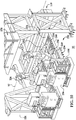
- the system includes a pair of scaffold-like frames 120.
- frame 120 includes a lower frame module 124 on each side of the assembly line path of travel 60 as generally shown (one assembly line described hereafter for convenience).
- the lower frame module 124 is manufactured and assembled to close dimensional tolerances and rigidly and removable secured to the plant floor 14 through threaded studs connected to mounting plates secured to the floor 14, typically concrete.
- the lower frame modules 124 are precisely spaced laterally from a predetermined and known centerline of the assembly line 60 in the assembly facility. The longitudinal position of the lower frame 124 along the assembly line is also determined through known 3-dimensional coordinate reference positions in the assembly facility. These positions may be defined using a large template or jig using the assembly centerline.
- an assembly cell reference center point 260 for the assembly station is determined as best seen in Fig. 12 .
- the predetermined reference point 260 provides an accurate and known location in the X, Y and Z dimensional coordinates from which other modular assembly system equipment for example the frames 120 are located from to support precision assembly operations along the assembly line.
- the lower frames 124 include an entrance point, for example the leading frame portion upstream, and an exit point, for example the trailing or furthest portion of frame 120 downstream.
- the lower frames 124 are precisely positioned longitudinally along path 60 from the known center or reference point 260 to provide a structurally rigid and dimensionally precise foundation for locating upper frames 130.
- the precision mounting location of the lower frames 124 along path 60 and precision mounting locations for the robots 150 connected to the frame 120 relative to the known reference point 260 of the assembly cell 56 provide accurate, precise and predictable orientation of the robots 150 for programming the movements of the robots 150 assigned functions in the assembly cell 56.
- the lower frames 124 are non-model specific.
- lower frames 124 are standard or generic and do not depend on which type of vehicle or vehicle body (or other product) will be built.
- the exemplary lower frames 124 are designed to handle or accommodate the building of substantially all passenger vehicles.
- the lower frames would be standard or non-model specific for other products that may have options or variations that can be ordered by customers.
- Each upper frame 130 is preferably precisely fabricated to small or close tolerances and mounted atop a respective lower frame 124 as generally shown (one described hereafter for convenience).
- Upper frame 130 includes vertical legs and an elevated floor 136 longitudinally extending along and parallel to path 60 forming a rigid scaffold-like assembly frame.
- Floor 136 is of a width 140 which is preferably about 1524 mm (60 inches). Other widths 140 and dimensions of upper frame 124 suitable for the application and known by those skilled in the art may be used.
- Precision-machined mounting surfaces (not shown) provide mounting points for assembly tools, for example programmable robots, although other assembly equipment and/or tools may be used.
- preferably three inverted multi-axis industrial robots 150 attach to the underside of floor 136 and extend down below floor 136 as generally shown.
- the upper frame 130 precision mounting surfaces accurately and precisely position the robots 150 relative to the upper 130 and lower 124 frames and assembly cell center point 260 providing a high level of dimensional and locational predictability and repeatability in the initial installed position and orientation of robots 150 with respect to the assembly cell for programing and operation.
- precision located mounting holes are provided in the upper frames 130 to accept modular robot mounting plates (not shown).
- the mounting plates for example, can be connected to the robots at the integrator's (i.e. vendor/supplier) facility with easy and precise connection to the upper frames 130 when installed in the assembly plant.
- tapered locating pins may be installed on the upper portions of the lower frame 124 and coordinate with apertures or other details in the mating upper frame 130.
- the tapered locating pins may be used to guide and position the upper frame 130 into 3-dimensional X, Y and Z precision location relative to the lower frame 124 and then secured in place with large bolts, other fasteners or other securing methods known by those skilled in the art.
- Lower 124 and upper 130 frames are preferably made from welded steel elements although other materials known by those skilled in the art may be used. It is understood that lower 124 and upper 130 frames may take other sizes, shapes and configurations than that shown consistent with the above description as known by those skilled in the art.
- each robot 150 is preferably housed in control cabinets 160 secured to upper frame floor 136 as generally shown.
- Other positions of the cabinets 160 suitable for the application and number of robots 150 (or other assembly tools and equipment) for a particular assembly cell 56 known by those skilled in the art may be used.
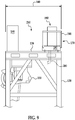
- AE pallet 170 includes a mounting surface or top 174 having a width 176 and vertical joists or supports 180 (three shown per pallet) as generally shown.
- AE pallets 170 may include a bottom 182 forming a rectangular pallet-like structure.
- AE pallet may further include a back panel (not shown) and a front panel (not shown).
- mounting surface 174 is shown as a top or upper surface, it is understood other mounting surfaces, configurations and orientations known by those skilled in the art may be used.
- mounting surface 174 is a rigid panel having a plurality of through holes or slots, mounting bosses, weld nuts and/or other features for mounting application equipment (AE) 190 suitable for the assembly operations in the assembly cell 56 and most preferably for a particular assembly tool, for example a robot 150.
- mounting surface 174 can be a rigid steel plate with holes positioned in a 100 millimeter grid pattern for ease of positioning and securing all types of AE devices 190.
- three (3) inverted robots 150 are connected to upper frame 130
- three (3) AE pallets 170 are preferably used providing the respective AE device 190 needed to support the respective robot 150 assigned an assembly task. As seen in Fig.
- AE devices 190 three (3) different forms of AE devices 190 are illustrated.
- a fluid storage and dispensing system 194 is secured to top 174 as generally shown.
- Consumable fluid materials such as sealants, adhesives, coolants and lubricants are common in vehicle body assembly lines.
- coolant or lubrication fluids such as water are considered consumable materials for purposes of the disclosure.
- the far right AE device 170 has a consumable materials fastener feeder 198 connected thereto.
- Such fastener feeders may include consumable rivets, weld studs, weld nuts, screws and other fasteners common to vehicle body operations known by those skilled in the art.
- the far left AE support 170 includes a third application equipment, for example a welding controller for a resistance spot welding of aluminum application.
- Other AE devices 190 needed to support common vehicle body (or other product) assembly operations may include equipment necessary to support welding operations including, but not limited to, resistance spot, seam, laser, brazing, piercing and clinching operations.
- Examples of consumables for seam or brazing operations may include welding wire or electrodes that are selectively fed by a feeder to the assembly tool in the assembly station as further described below. It is understood herein that reference of supply of consumable or other materials from the AE devices to the assembly tool, for example a robot, also includes the supply to any end effector or other tool connected to the assembly tool. Other AE devices 190, and consumable materials used thereby, known by those skilled in the art may be packaged and secured to a respective AE pallet 170. Although described as useful with robots 150, it is understood that AE devices 190 can be used with other assembly tools and equipment needed to support assembly and manufacturing line processes and operations known by those skilled in the art.
- AE pallet 170 includes hooks 188 rigidly mounted to two or more vertical supports 180 as best seen in Fig. 6 .
- Exemplary hooks 188 laterally extend outward from vertical supports 180 and engage cooperating structures, for example slots 144 in a laterally outward facing surface 142 of upper frame 130 forming a localized lateral continuation of floor 136 as best seen in Fig. 7 .
- the coordinating mounting holes may be in the floor 136.
- AE pallet 170 is mounted atop upper frame floor 136 through mechanical fasteners as generally shown (space shown between 170 and 136 for ease of illustration).
- the width 140 of upper frame 130 may be increased (not shown) to accommodate the width 176 of AE pallet 170 while allowing adequate space for walkway 210 as described below.
- Other structures, orientations and fastening methods for removably mounting AE pallets 170 to upper frame 130 known by those skilled in the art may be used.
- AE pallet 170 is configured to form a pallet-like support structure for any AE device 190 to provide consumable materials, other materials, or services (for example electrical power, fluids or data) to the assembly line, preferably adjacent exemplary industrial robots 150.
- pallet 170 width 176 is approximately 914 mm (36 inches).
- the combined widths 140 of upper frame 130 floor 136 and width 176 of AE support are less than 2438 mm (96 inches) which is the standard width of a commercial boxcar shipping container.
- Other widths 140 of floor 136 and AE pallet 170 may be used to suit the particular application and assembly line environment. It is also in the disclosure that the widths can comprise two or more pieces for ease of shipping and then assembled at the system integrator or on site at the assembly facility.
- the exemplary pallet 170 is preferably configured, oriented and adapted to be lifted, carried and elevated by a forklift common in assembly plants.
- the modular AE pallets 170 are shipped "empty" to a supplier/vendor responsible for providing AE devices 190 to support assembly operations in one or more assembly cells 56 along one or more assembly lines 38-45.
- the vendor can design and package the AE devices 190 in the space provided by the modular pallet170, securely mount the AE device 190 to the top 174 and fully test and commission the operation of the equipment at the supplier's facility thereby providing tested and ready to use equipment on installation at the assembly plant.
- AE devices 190 may be mounted in other orientations with respect to pallet 170, for example connected to the underside of top surface and extending downward. Other mounting and orientations of AE devices 190 to pallets 170 known by those skilled in the art may be used.
- AE pallets 170 provides for several configurations depending on the assembly operations for a particular assembly station 56.
- a safety rail 146 normally installed to upper frame surface 142 or floor 136, is simply disconnected from upper frame floor 136 and mounted to rail connection points (not shown) on AE pallet 170 as generally shown.
- Securing AE pallets 170 and reconfiguring the AE devices 190 for assembly cell 56 can be done in a matter of minutes versus hours or days with conventional assembly systems.
- Conduit 200 includes one or more of cables, wiring harnesses and/or pipes, 202, 204 and 205 positioned between the AE devices 190 and the assembly cell are shown.
- conduit 200 may be a single or multiple conduits/cables/pipes 202, 204 and 205, used to route, for example, an electrical and/or data cables 202 for the transfer of electrical power and information data from the control cabinets 160 to supply the necessary electricity and data to the AE devices 190 to, for example, power a fluid distribution pump 194 to supply pressurized adhesive or sealer to robot 150 or other assembly tools or cell equipment.
- conduit 200 may be a single or multiple conduits/cables/pipes 202, 204 and 205, used to route, for example, an electrical and/or data cables 202 for the transfer of electrical power and information data from the control cabinets 160 to supply the necessary electricity and data to the AE devices 190 to, for example, power a fluid distribution pump 194 to supply pressurized adhesive or sealer to robot 150 or other assembly tools or cell
- conduit 200 may include a cable 204connected between the AE device 190 and the assembly tool exemplary robot 150 to provide consumable materials and other materials, data and services to the assembly tool robot in order for the robot to perform the predetermined and preprogrammed assembly tasks in coordination with the application equipment 190 in the assembly cell.
- conduit 200 may include a pipe 205 is connected to the AE device 190 and routed through or around the AE pallet 170, under upper frame 130, through or around robot wrist 152 to the end effector 156 for the routing of consumable materials to assist assembly operations for that particular assembly tool. For example, it is common along vehicle body assembly lines to install adhesives, sealants and weld studs to the partially completed vehicle body in assembly cell 56. Where a robot 150 is tasked with welding operations, the fluid dispensing system 194 may provide water or other fluids to cool the equipment for continuous operation.
- consumable materials for example rivets, screws, or weld studs
- Additional AE devices may be installed on the same AE pallet to further support, for example, a seam welding robot through feeding of consumable welding electrode through conduit 200 to support the welding operation.
- conduit 200 could be a pipe or casing separate from the individual cables/wires and pipes described above, or may simple be the cables/wires and pipes themselves.
- conduit 200 may include hoses or pipes for the transport of fasteners into the assembly cell.
- AE pallet 170 includes one or larger routing apertures (not shown) in top 174 and open face 178 for the ease of routing conduit 200 laterally toward upper frame 130.
- the assigned robot 150 or other assembly cell tools would include the appropriate coordinating and reciprocal connectors so conduits 200 and/or 202, 204 and 205 can be rapidly connected for communication of consumable materials, data and other items on installation of the modular AE pallet 170 to upper frame 130 as described.
- Other communication lines, conduits and routing techniques and connections known by those skilled in the art may be used.
- the conduit 200 may simply be routed around the AE pallet floor versus through apertures in the floor as described.
- conduit 200 may come installed with the AE pallet and AE device as transferred into the assembly facility or may be largely, if not wholly installed in the assembly station.
- the AE device 190 may have a short conduit or simply connectors on the AE device 190 so it can be rapidly connected and placed in communication with the assembly cell control cabinet and/or the assembly tool in the manners described.
- I combination of conduits 200 is also contemplated.
- both the assembly station and AE device may have a conduit with coordinating connectors which are engaged on installation of the AE pallet to the frame.
- the AE pallet 170 comes "pre-wired" and includes coordinating connectors on the pallet 170.
- the pallet 170 may have common connectors or a bank of plugs wherein the AE device plugs into the pallet 170.
- wires/cables and pipes preinstalled in the assembly station are routed and plugged into another bank of connectors/plugs which place the AE device 190 in communication with the assembly tool and control cabinets in the manners described.
- Other structures and methods of connecting the AE pallet and AE device in communication with the assembly station known by those skilled in the art may be used.
- the entire first pallet 170 can be disconnected and replaced with a replacement first modular pallet 170 with a pre-installed and tested replacement first AE device 190 with minimal assembly line downtime and logistical disruption.
- This modularity and plug and play connectively will greatly reduce critical downtime of the assembly line for repairs, replacement and time consuming maintenance of application equipment 190.
- the modularity also is a major advantage for vehicle model and other product changeovers requiring reassignment of a robot 150 assembly operation or other assembly line tools/ equipment.
- a second AE pallet 170 with a second AE device 190 suitable for the new assembly tool or operation can be quickly mounted to upper frame 130 through a forklift or existing gantry crane and connected to the retasked or new assembly tool through conduit 200 as described above.
- the second AE pallet would be the same modular AE pallet 170 used with the first AE device, but having a different, second AE device 190 connected to it suitable for the alternate assembly operation by the assembly tool. It is contemplated that more than one type or form of modular AE pallet 170 may be used to accommodate the various AE devices 190 or assembly line operations.
- the elevation of the application equipment 190 further removes such equipment from traditional placement on plant floor 14 and routing of the communication or support lines up to the inverted robots 150 which typically required dedicated frames to support and route the lines, for example hoses and fastener conduits.
- the dimensional size of floor 136 and the placement of control cabinets 160 and application equipment 190 preferably provides for a walkway 210 along floor 136 longitudinally along upper frame 130. In one example, this is advantageous for access and maintenance of systems in the control cabinets 160 and AE devices 190 positioned thereon or connected thereto. Further, as the AE device 190 which provides consumable items such as adhesives and fasteners to the assembly cell, these consumable materials need to periodically be replenished. Walkway 210 provides a pathway for operators (see Fig. 8 ) to maneuver and restock these consumables for continuous assembly station operation. As an example shown in Figs.
- a drum of fluid can be raised by a forklift and installed atop floor 136.
- a dolly or cart can be used by an operator to move and replace an empty fluid storage container for a fluid dispenser 194. Where fasteners need to be replenished, an operator can manually carry a box of fasteners and load them in the application equipment hopper for future distribution to the robot 150 by the application equipment 190 and conduit 200 as described.
- Distribution deck 212 is used to assist in the supply or replenishment of consumables, for example, adhesives, sealants, fasteners and other materials that are used by the various AE devices 190 mounted on AE supports 170.
- deck 212 is positioned at one or both ends of an assembly line 40 - 45 ( Fig. 1 ) and has a platform which is preferably directly adjacent and at the same elevation as floor 136 of the upper frame 130 and in the exemplary AE pallet floor 174 shown in Figs. 4 , 7 and 8 .
- consumables for example 55 gallon drums of sealant 216 for use in fluid distribution device 194, would be raised up to platform 214 by a forklift or other device and deposited on the platform. Operators can manually, or through aid of a moving device, move by hand cart the consumables deposited on deck 212 along path 210 to the appropriate AE pallet 170 where the consumables are needed. This is very advantageous for continuous operation of the AE devices 190 and assembly station 56. The position of the AE devices 190, consumables 216 and workers above the assembly cell 56 for this work is very advantageous for plant logistics, efficiency and safety. Other methods of depositing the consumables 216 on platform 214 and movement along path 210 may be used as known by those skilled in the art.
- a distribution deck 212 would be provided at one end of each assembly line 40-45 adjacent to the material load and sequence area 30.
- distribution deck 212 may be continuous and span several or all assembly lines 40-45 or be individual to each line where consumables are needed to support assembly operations.
- the consumables 216 would travel the least distance from the material entry area 20 to the assembly line and thus further simplify assembly plant floor congestion and logistics.
- Other configurations and locations of distribution deck 212 known by those skilled in the art may be used without departing from the present disclosure. It is further understood that distribution deck 212 may serve other purposes than receipt of consumable materials as known by those skilled in the art.
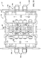
- an example of an aspect of system 10 includes modular assembly tool (AT) platforms or trays 220 to provide assembly tools or other assembly equipment, for example programmable multi-axis robots 226, additional AE devices 190 and associated accessories or devices used thereby.
- AT assembly tool
- modular robot platforms 220 are illustrated (two shown in Fig. 10 , four shown in Fig. 11 ) at floor level 14 of the assembly cell 56.
- a floor-positioned industrial multi-axis robot 226 having a principal axis of rotation 230 (shown in Fig. 13 ) is mounted to a base 236.
- base 236 includes a base plate having precision, most preferably equally spaced, mounting points or holes 240 for mounting the robot 226.
- the exemplary base plate is preferably mounted to frame rails 246 that extend laterally outward from assembly path 60 as generally shown. Rails 246 preferably also include precision positioned mounting points 250, for example holes, along the length of the rails.
- the exemplary base plate and rail mounting points provide predetermined, highly predictable and repeatable mounting points in the Z, Y and Z dimensional coordinates for the robot relative to the rails 246.
- rails 246 are rigidly connected to a continuous product conveyor or other equipment positioned along the assembly line or path 60 relative to the assembly station reference point 260 as best seen in Fig. 11 .
- Connection of the modular AT platform 220 including exemplary frame rails 246 can be made through use of rigid brackets 254 mounted in holes 252 as generally shown or other connection devices and configurations known by those skilled in the art.
- conveyor rail holes 252 are equally spaced apart and generated with close/small dimensional tolerances for accuracy and precision mounting of the AT platforms 220.
- Mounting points 252 may include other structures to securely connect AT platform 220 to the conveyor or other assembly station structure for the particular application.
- platform 220 base is shown including rails 246, it is understood that the frame or support structure can vary depending on the assembly tools and AE equipment and application.
- support 220 may include a pallet-like structure as 170 so the AT platform 220 can be transferred and moved to the line by a forklift.
- the exemplary base plate may include a heavy steel plate with a grid of equally spaced holes 100 millimeters (mm) for ease of mounting the assembly tools and AE devices.
- the plate may be supported by rails 246 or other structures known by those skilled in the art. It is understood other platform 220 constructions to positon and mount platform 220 to the conveyor or support structure 110 can be used as known by those skilled in the art.
- the exemplary precision base plates 236, rails 246 and mounting holes 240, 250 and 252 provide for accurate, precise and repeatable X, Y and Z coordinate dimensional positioning of the robot 226 relative to the known assembly cell center point 260 and other assembly station equipment thereby facilitating rapid placement, plug and play and programming of the exemplary robots 226 for assembly operations once installed at the assembly plant.
- AT platform 220 may be connected to mounting plates that are installed in the assembly plant floor in a similar manner to those described for mounting assembly station lower frames 124 described above and below for Fig. 15 .
- Modular AT platforms 220 may further include the necessary control cabinets 156 to power and communicate programs and data with the respective assembly tools and AE devices 190 installed on support 220.
- the assembly tools, AE devices 190 and control cabinets can be pre-installed on base plates 236 and/or frames/platforms 246 at the assembly tool or other supplier's facility and be fully commissioned/tested before shipment to the system integrator or directly to the assembly plant for installation.
- the AT platforms 220 can be pre-wired and cabled as necessary with a conduit 200 for plug and play installation and operation at the assembly facility as similarly described above.
- the AE devices 190 can supply consumables and other materials and functions to the assembly tools, for example robots 226, as described for AE pallets 170.
- the preferably self-contained, operational and initially tested/commissioned modular AT platforms 220 and equipment thereon can be transported to the assembly line, rapidly secured and connected to the existing assembly station equipment and control system in a plug and play manner as generally described for AE pallets 170 and AE devices 190. This greatly reduces the time and effort to locate, program and calibrate the assembly tool into the assembly station for rapid, small/close dimensional tolerance production operation.
- any control cabinets and AE devices required for AT platform 220 can be mounted to the base 236 or other structure described above or can be stand alone devices that are separately and independently positioned and secured in proximity to the AT platform assembly tool.
- an example of an AE device 190 can be automated weld tip dressers (not shown) precisely positioned on a larger base plate 236 or frame relative to the robot. For example, at scheduled intervals, the robots 226 can be programmed to run a maintenance cycle wherein the robots position the end effector spot weld gun weld tips in engagement with the weld tip dressers to condition the weld tips for optimum and continuous operation of the assembly cell.
- Other AE devices 190 discussed above, and methods of coordinating, integrating and connecting and connecting these devices with assembly tools known by those skilled in the art may be used.
- fence 270 includes a first frame 272 and a second frame 273 as generally shown.
- each frame 273 and 273 includes a vertical post 274, an upper support 276, an upper rail 278 and a lower rail 280.
- one or more front panels 286 extending along parallel to assembly path 60 and side panels connected between the upper 278 and lower 280 rails are used.
- each fence frame is rigidly mounted to and cantilevered from the assembly station lower 124 and upper 130 frames as generally shown.
- Front 286 and side 290 side panels can be made from steel, aluminum or other materials, for example transparent materials like polycarbonate, forming a grating or barrier to keep personnel and objects from unauthorized entry into the assembly station.
- Other materials, sizes, shapes and configurations of the panels and frames known by those skilled in the art may be used.
- the front panel 286 is slidingly mounted in guides 296 and connected to a retractor device 300.
- a retractor device 300 includes an electric motor 302 mounted to upper frame 130, a cable 304 and a stationary pulley 308 as generally shown.
- the retractor is selectively operable by an operator or control system (not shown) to raise the front panel from a first lower position 310 proximate floor 14 to a raised upper position 316.
- Upper position 316 is preferably of sufficient height such that operators and other equipment, for example forklifts, can enter assembly cell 56 and access and move assembly tools and other equipment to and from assembly cell 56 as necessary in the normal operation of the facility.
- the guides 296 are preferably positioned laterally outward from the assembly tool robots 226 and laterally inward from control cabinets 156 and AE devices 190 as generally shown. This provides access to the assembly tool controls and AE devices 190 to, for example replenish consumable materials provided to the assembly tools by the AE devices 190.
- Other positions of fence front and side panels known by those skilled in the art are within the present disclosure.
- the front panel 286 is normally positioned in the lower position 310 when the assembly station 56 is energized or in active assembly operations.
- retractor device 300 can be engaged manually or through signals received from a local or central controller (not shown), to raise front panel 286 to the upper position 316 allowing personnel and equipment easy access into the cell 56 without the need for disassembly or partial removal/relocation of traditional protective fences or guards.
- a local or central controller not shown
- retractor 300 can take other forms and features known by those skilled in the art. For example, front panels can be manually raised and locked into place with pins or other devices and then manually lowered to continue assembly operations.
- a flow chart of an exemplary process 400 to build and install AE pallets 170 in an exemplary robot assembly tool application is shown.
- the exemplary process at step 410 it is determined the number and specific assembly operations that will be performed in one or more assembly stations 56, for example exemplary vehicle body assembly operations executed by industrial robots 150 with various end effectors for a variety of assembly operations.
- a plurality of modular, and preferably identical, AE pallets 170 are fabricated having the structural and spatial features described in the examples above in step 420.
- the modular AE pallets 170 are shipped "empty" in large quantities to a respective vendor for installation of an AE device (or devices) 190 by the vendor for a particular robot 150 or other assembly tools.
- the installed AE device 190 on the modular pallet 170 is pre-wired/pre-cabled with conduit 200 including power and data communication lines 206 appropriate for the assembly station, assembly tool and/or assembly operation and mated with coordinating connectors for attachment with connectors on the control cabinets, the robots 150, other assembly tools or other assembly cell equipment.
- the AE device 190 is then preferably tested/commission at the vendor or system integration to ensure proper operation before shipment to the assembly plant. In some AE devices 190, advanced testing and pre-programming of software can be performed at the vendor with minimal or no modifications and adjustments being necessary at the assembly plant for volume production.
- the modular AE pallet 170 and installed AE device 190 is shipped to an intermediary system integrator facility, or alternately directly to the assembly plant, and matched with the prefabricated assembly scaffold frame 120, conveyors, non-model specific equipment, for example pre-installed robots 150, and selected model-specific equipment assigned the assembly task supported by the application equipment 190.
- the pallet 170 may be elevated into position proximate upper frame 130 and floor 136 by a forklift or other lifting mechanism.
- the modular pallet 170 is then engaged to the upper frame 130 in the examples described, for example engagement of hooks 188 with coordinating slots 144 in upper frame 130.
- step 450 the application equipment conduit 200 is routed and the prewired or pre-cabled lines 202, 204, 205 and/or 206 are connected to the pre-wired or pre-cabled robot 150, control cabinets or other cell equipment for rapid install, communication and operation of the assembly cell 56.
- consumables 216 are transferred to and placed on upper frame(s) 130 through distribution decks 212 to supply the respective AE devices 190 with needed materials to support the predetermined assembly operations.
- the entire pallet 170 is preferably disconnected from the control cabinet, robots and upper frame 130 and quickly replaced with another pallet170 with replacement or alternate AE device(s) 190.
- the existing AE pallets 170 with AE device 190 is disconnected and swapped out with an alternate pallet 170 having the appropriate AE device 190 for the new assembly task.
- the process 400 may equally be applied to AT platforms 220, or the AE devices 190 used therewith as described.
- the modular AT platform 220 can be disconnected and replaced with a new or alternate assembly tool and AE devices 190 as required, and connected to the conveyor or other equipment as described above.
- the mounting points of the base 236, rails 246 and conveyor provide for rapid reconnection of a replacement AT platform 220 relative to the assembly station and/or assembly station reference point 260 thereby minimizing reprogramming or calibration of the new assembly tool.
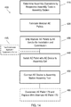
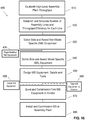
- FIG. 15 an exemplary method 500 of assembling or installing a modular vehicle assembly system 10 is illustrated.
- system 10 infrastructure such as frames 120, conveyors or transports 48, assembly tools for example robots 150/226 and other unique tooling is assumed to be already complete, but understood can vary as known by those skilled in the art.
- the centerline of assembly line 60 is preferably determined.
- the centerline is determined from existing X, Y and Z dimensional coordinate reference points defined by the assembly plant.
- An assembly cell reference point 260 may be determined as described above.
- step 510 lower frame 124 mounting plates are secured to the assembly plant floor 14 in predetermined locations relative to the assembly line 60, assembly center line and/or assembly cell centerpoint 260 as generally described and illustrated.
- step 520 the lower frames 124 are removably secured to the mounting plates on both sides of the assembly line path 60.
- the attachment points where the lower frames attach to the floor mounting plates are preferably laterally spaced from the assembly line centerline and longitudinally positioned along the assembly line at predetermined locations.
- the lower frames 124 are mounted to the floor at predetermined locations which then the below conveyor is positioned and mounted with respect thereto.
- the assembly cell reference point 260 may then be established based on the installed frame and conveyor.
- step 530 the vehicle conveyor system along assembly path 60 is installed as well as any framing needed where a return conveyor along a return upper path 84 is installed.
- a transverse tooling conveyor 112 may be installed.
- the lower frames 124, and conveyors 50/52/90/110 defining respective assembly paths 60/78 and 84, tooling conveyor 112 (if an overhead conveyor system) and protective fences 280 are considered to be vehicle non-model specific equipment. In other words, these devices are preferably wholly standard and used for all vehicle models or other products to be assembled.
- the assembly station upper frame 130 is installed and secured atop the lower frame 124.
- the assembly tool industrial robots 150 and control cabinets 160 are pre-installed on the upper frame 130 as a unit by a vendor prior to delivery to the assembly cell and prior to securing it to lower frame 124.
- the upper frames 130 although may all be modular, identical and standard in construction, are shipped "empty" to a vendor for installation of model-specific equipment, for example preprogrammed assembly tool robots 150 and appropriate control cabinets 160.
- the vendor similar to that described for AE pallets 170 and AE devices 190, installs and commissions the assembly tools and/or model specific equipment on upper frame 130 (or as much as practically possible depending on the equipment and application) at the vendor or system integrator's facility prior to shipment to the assembly facility for installation into the assembly station 56 and final commission for production assembly.
- the robots 150 and control cabinets 160 may be installed following installation of the upper frame 130 onto the lower frame 124 in the assembly facility or in another sequence as known by those skilled in the art.
- exemplary step 550 the AE pallets 170 with preinstalled and commissioned vehicle/product model specific AE devices 190 are transported to the assembly facility and secured to upper frames 130, coordinated with the appropriate control cabinet, and electronically connected to the robot 150, end effector or other assembly cell tools and equipment as generally described above.
- the same or similar process would be carried out for any model specific modular AT platforms 220 for a pallet-style conveyor system ( Fig. 2 ) as generally described above.
- step 560 unique vehicle or product model specific tooling trays, tooling, fixtures and other equipment are delivered and installed to complete the operational assembly station equipment.
- any remaining protective fences 270 to accommodate the model specific equipment are installed and/or enabled. It is understood that depending on the assembly cell, part or all of the protective fence or fences 270 may be installed earlier as described or where appropriate in the cell assembly process.
- FIG. 16 another exemplary aspect is illustrated.
- business method or solution 600 for purchasing/sourcing, fabricating and installing equipment for a vehicle body or other product assembly line is illustrated.
- the exemplary process is particularly useful with the modular system 10 described above, but may be used with other assembly operations for other products. It is understood the method 600 can be used for products other than vehicle body assembly as known by those skilled in the art.
- step 610 establishes high level assembly plant parameters including plant size and target vehicle (or other product) throughput (vehicles/products per hour, shift, week and/or month or other periods or variables).
- step 620 the assembly plant is preferably simulated three-dimensionally through CAD-CAM or other simulation tools to establish the number of assembly lines and throughput and/or efficiency of each individual assembly line. It is understood this step could be done manually or through other conventional processes and mechanisms known by those skilled in the art.
- step 620 the assembly operations and equipment necessary for completing the assembly tasks are determined for each assembly line 40-45.
- the equipment is initially determined to be vehicle/product non-model specific or vehicle/product model specific.
- equipment is vehicle non-model specific if the equipment is useful in assembly regardless of which vehicle model or body style is being assembled.
- vehicle non-model specific and model specific for the described system 10 is:
- the non-model specific equipment is placed out for competitive bid contract and awarded to a single or minimum number of vendors.
- all vehicle non-model specific assembly equipment for all assembly lines may be sourced to one vendor.
- the non-model specific equipment is standard and/or modular and at least partially pre-designed. This reduces and minimizes prior processes which took months and months to largely, if not wholly, custom design the non-model specific infrastructure and equipment for every assembly plant.
- the process to bid and award happens far more quickly than the conventional process.
- fabrication can begin on the system 10 modular non-model specific infrastructure and equipment.
- step 640 based on the predetermined and preferably already designed modular, non-model specific equipment, the vehicle model specific assembly equipment is specified and competitively placed out for supply bid contract.
- the bids for the model specific equipment can go out much faster, possibly many months faster, as the non-model specific designs, or a great many portions thereof, are already complete.
- supply contracts for the model specific equipment for each assembly line 40 - 45, or combinations of assembly lines may be awarded to other integrators/vendors.
- the non-model specific equipment is already partially or wholly awarded and preferably fabrication already underway.
- each winning model specific vendor would be responsible for the required product throughput performance for the awarded lines. It is understood that steps 635 and 640 can occur simultaneously or even switched depending on how long the lead times are for effective management of the quotation process.
- step 650 the awarded model specific equipment is designed. During this period, fabrication of the awarded non-model specific in step 635 continues. Where appropriate, in step 655 installation of the completed non-model specific equipment can occur at the assembly facility for initial commission. Where non-model specific equipment is to be delivered to the model-specific vendor, for example empty upper frames 130, AE pallets 170 and AE platforms 220, these can be shipped to the model specific vendors in step 660.
- exemplary step 670 the model specific equipment is fabricated and commissioned/tested.
- AE pallets 170, AE supports 220 and necessary AE devices 190 are installed, wired and plumbed with the appropriate cables and harnesses and tested at the vendor's facility as generally described above.
- the tested vehicle model specific equipment arrives and is installed at a system integrator or directly at the assembly plant.
- the AE pallets 170 with installed AE devices 190 the AE pallets are lifted into positon and quickly secured to upper frame 130 as previously described.
- the conduit 200 which may include one or more of 202, 204, 205 and 206 are quickly and readily connected to the control cabinets, robot 150 (or other assembly tools or equipment) and coordinated with the equipment in the assembly station for rapid and already proven operability avoiding may problems and delays in conventional systems. This similarly occurs for modular AT platforms 220 as previously described.
- Other model-specific equipment is fabricated, tested and installed in the same manner.
- the fabricated modular upper frame 130 may have been shipped to the model-specific vendor.
- the robots 150, AE pallets 170, AE devices 190, and control cabinets 160 may arrive to the assembly plant and be installed as a completed unit atop the lower frames 124.
- first AE device 190 fails or needs maintenance or refurbishment
- the entire first AE pallet 170 or platform 220 that the respective failed first AE device 190 or assembly tool is secured to can be quickly disconnected and removed from upper frame 130 or conveyor and replaced.
- new (or refurbished) and tested replacement first AE device or alternate second AE device 190 preinstalled on an alternate or second AE pallet 170 can be raised, secured to upper frame 130 and connected to the control cabinet, robot and assembly cell in a matter described above.
- the individual assembly lines 40-45 throughput requirements are monitored and enforced on an assembly line-by-line basis, and the respective equipment vendor which supplied the particular model specific line and/or equipment is held accountable to meet the predetermined performance targets, to ensure the overall assembly line and assembly plant vehicle/product throughput specification is achieved.
- modular AE pallets 170, AT platforms 220 and fence 270 may all be included, or separately included in various combinations to suit the particular application, to form the system 10 structure and methods as described and/or illustrated herein.
Description
- The invention generally pertains to the field of product and vehicle assembly.
- Traditional high volume manufacture and assembly of products, machines and vehicles has occurred in large assembly plants. These assembly plants have included multiple assembly lines where components are gathered, assembled and connected together. In the manufacture and assembly of vehicular bodies, the bodies typically include a skeleton of sheet metal components that are welded together through resistance spot welding, seam welding and brazing techniques to form what are commonly called "body-in-white" (BIW) structures.
- With the growing need to efficiently build vehicles and accommodate varying consumer demand, assembly plants have strived to employ flexible build processes so that different vehicles and varying vehicle models including alternate vehicle bodies, can be built along the same assembly lines. The ability to quickly change over from building one type of body to another causes significant difficulty for facilities due to the limited amount of space around assembly lines and the time required to change over equipment and components that are specific to one vehicle body.
- The design, build, installation and commission (testing or prove-out) of new assembly lines is an enormously time consuming and expensive endeavor for both suppliers and the customer vehicle original equipment manufacturers (OEM's) ultimately responsible for operation of the assembly facilities and production of the vehicles. Due to increased competition and consumer demand, there is continuous pressure from the OEM's for lower cost and higher efficiency assembly systems (higher vehicle or unit per hour throughput) and for those assembly systems to be 100 percent operational in a shorter amount of time.
- Due to the multiple assembly systems, equipment and components that require sequenced operation to assemble a vehicle (or other product), the design of the overall assembly line traditionally required many stages. For example, the final design of equipment, for example called "Time B" equipment, that relies on a supporting structure, for example called "Time A" equipment, traditionally could not be completed until the design of its Time A supporting structure is complete. Once the various Time A support infrastructure and individual assembly systems were designed, built and installed, a substantial portion of the commission or testing of the Time B equipment traditionally could not occur until all of the Time A support structure and equipment is delivered and installed at the OEM assembly plant. This is further complicated by OEM's typically awarding portions of the assembly line Time A and Time B equipment to many different suppliers to leverage the respective supplier's expertise. If a supplier falls behind in the design, build or installation of Time A equipment, that can delay Time B equipment suppliers causing a cascading of delays through the remainder of the design, build, installation and commission stages. It would be further advantageous to have as many of the assembly equipment and systems be generic or non-model specific. That is, these systems and equipment may be used to build most or all variations of a product or vehicle which may have different models or features. These non-model specific systems and equipment (Time A) could then be fabricated, installed and commissioned even when final decisions about the product to be produced have not been made (which affect the Time B non-generic or model-specific assembly equipment and systems).
- It has further been time consuming and costly for vehicle OEM's to change over an assembly plant or assembly lines to a new vehicle model or different vehicle altogether. Even simple to moderate changes to the assembly line equipment infrastructure can take days or weeks to complete leading to costly production downtime.
- Prior assembly systems have employed specific assembly plant layouts to decrease the plant floor space required and increase efficiency in operations and vehicle throughput. For example, the ComauFlex system, produced by the same assignee of the present invention, has been widely employed by OEM's the details of which can be reviewed in
U.S. Patent No. 8,201,723 , briefly discussed below. Details of variations of the ComauFlex assembly plant layout systems can further be found inU.S. Patent Nos. 8,869,370 ;8,713,780 andU.S. Patent Application Publication 2012/0304446 all assigned to assignee of the present invention. These prior systems further reduced the need to store to-be-installed components and subassemblies next to the assembly line and specific assembly stations or cells which cluttered the assembly floor and complicated logistics. - Prior assembly systems have employed some modular vehicle assembly subsystems which provided advantages in new installations and accommodating batch and random vehicle builds where different vehicle models or types of vehicles could be built along the same assembly line with reduced changeover time. Prior assembly subsystems have employed modular robotic assembly stations or cells which could be placed end-to-end to accommodate a specified assembly line or series of operations. For example, each assembly station or cell included a modular, precision-manufactured to close tolerances scaffold frame structure and could be selectively equipped with the necessary number of industrial, multi-axis robots and end effectors for a specified assembly operation. Details can be found in the above-referenced
U.S. Patent Nos. 8,201,723 ;8,869,370 ;8,713,780 andU.S. Patent Application Publication 2012/0304446 . - Despite the numerous efficiencies and advantages prior assembly systems provide, many of the above-referenced complexities and disadvantages continue in the design, build, assembly and commission of these equipment and process subsystems, and the assembly system as a whole, in the field. For example, peripheral equipment used in vehicle assembly, for example liquid sealant dispensing devices and fastener feeders, required to support the robot assembly operations at a particular assembly station are traditionally placed on the plant floor and separate conveying systems required to transfer the sealant or fasteners to the robots positioned in the assembly cell for use. As another example, where floor-mounted robots are needed in an assembly cell, much time and effort is traditionally needed to precisely locate and mount the robots in positional relation to the other robots and equipment in the assembly cell. As another example, safety fencing used around an assembly line or cell cannot be designed and tested until most of the assembly cell equipment is designed and installed at the assembly facility. A modular assembly system according to the preamble of
claim 1 and a method for providing application equipment for use in assisting assembly operations according to the preamble ofclaim 14 are known from the above mentionedU.S. Patent No. 8,201,723 . - Examples of the present invention include a modular vehicle assembly line having a plurality of assembly cells having modular systems and equipment which improves on the above complexities and disadvantages in prior assembly systems and methods. The present invention provides a system as detailed in
claim 1 and a method as detailed inclaim 14. Advantageous features are provided in the dependent claims. - In one example, a modular application equipment (AE) support pallet device is selectively used to elevationally support and secure application equipment, for example liquid sealant storage tanks and distribution pumps, above the assembly line and assembly tools, for example robots. The modular pallet is selectively connected to the assembly cell frame directly adjacent to, or in close proximity to, the robot (or other assembly tools or equipment) using the specific application equipment and further provides a simple logistical path to convey the consumable material, sealant, fasteners etc. directly into the assembly cell and the robot for application. In an example of a method of the invention, the modular pallet device can be pre-constructed and shipped to the application equipment supplier wherein the application equipment can be mounted and tested at the supplier prior to delivery and installation at the assembly plant. Power, data and material conveying cables and hoses for the mounted peripheral equipment can simply be connected to coordinating equipment at a system integrator's facility or directly at assembly plant for a "plug and play" device enabling efficient installation, connection and commission/testing at the assembly plant.
- In another example, a modular assembly tool (AT) platform or tray is provided to easily locate and secure required assembly tools and associated AE devices to the modular assembly cell infrastructure. In one example, a floor-level modular robot platform is provided. In the example, an industrial programmable robot, control cabinet and associated accessory devices are preinstalled on a modular AT platform or frame which coordinates with the existing modular assembly cell infrastructure. The modular support platform similarly allows the equipment to be pretested prior to arrival at the system integrator or assembly plant and provides quick and precise positioning with the existing modular assembly cell infrastructure. The simple, secure and precise positioning of the robot relative to the platform, and the platform relative to the assembly cell or station, provides immediate, predictable and highly repeatable location of the robot to the other assembly cell equipment greatly reducing the time and effort to positionally orient, program, and calibrate the robot over traditional devices and methods. The exemplary modular AT platform further provides secure and predictable positioning of AE devices relative to the robot, for example weld tip dressers for spot welding gun end effectors connected to the robots, further adding to plug and play advantages on installation at the assembly plant as described above.
- On the need for significant maintenance of the application equipment, or a model changeover at the assembly plant, the modular AE pallets and AT platforms having non-model specific or model-specific AE devices and assembly tools are simply "unplugged" from the non-model specific assembly structures and replaced with the new, refurbished and/or AE devices or assembly tool equipment for the new vehicle model that has been tested/commissioned prior to arrival at the assembly facility or line.
- In another example a modular guard fence is used with one or more aspects of the modular assembly station and modular inventive aspects noted above and discussed below. In an example, the guard fence includes a frame that is cantilevered from the assembly frame and, may, but in a preferred aspect, does not require connection to an assembly plant floor which was expensive and time consuming in conventional safety fences and guards. The exemplary fence includes an upper position and a lower position allowing selective access to assembly tools in the assembly station. In one example, a front panel is positioned between the assembly tools and control cabinets and AE devices of an AT platform. This prevents unauthorized access to the assembly tools while allowing access to the control cabinets and selected AE devices while the assembly tools are in operation.
- In another example a method of establishing and purchasing a vehicle (or other product) assembly line is presented. In the example, an assembly plant throughput is established and the number of individual assembly lines forming the complete assembly line is determined. The throughput for each assembly line is calculated to meet the overall throughput target. The required assembly line equipment and services are divided up into non-model specific infrastructure equipment and services that are non-vehicle model specific and vehicle model-specific systems.
- The non-model specific systems may include the modular frames, conveyors and AE pallets and AT platforms. The non-model specific equipment is singly sourced to a supplier or a minimal number of suppliers. The vehicle model-specific assembly equipment is competitively bid, preferably on an individual assembly line by assembly line basis, the supplier awarded the individual line or lines being responsible for meeting the individual line throughput specification.
- The method provides at least the advantages of simultaneous and parallel design activities for non-model specific and model specific equipment, immediate design release of the modular non-model specific technical details of the assembly lines, increased commission of the equipment at the suppliers and rapid installation and final commission at the assembly plant through connection of the modular assembly line components and application equipment mounted thereto. This results in compressed timing to design and install an assembly facility at lower cost and overall lowered business risk which is more evenly shared between the OEM and suppliers awarded portions of the business.
- Other applications and aspects of the present invention will become apparent to those skilled in the art when the following description providing examples of the invention are read in conjunction with the accompanying drawings described below.
- The description herein makes reference to the accompanying drawings wherein like reference numerals refer to like parts throughout the several views, and wherein:
-
Fig. 1 is a schematic of an example of a prior art vehicle assembly plant layout and assembly lines; -
Fig. 2 is a perspective view schematic of one example of a prior art vehicle assembly station having a pallet-style vehicle conveyor; -
Fig. 3A is a perspective view schematic of an example of a modular vehicle assembly station of the present invention with an exemplary overhead-style conveyor and peripheral support device being installed; -
Fig. 3B is an alternate perspective view schematic of the example shown inFigure 3A with several modular pallet devices installed on both sides of the assembly station; -
Figs. 4A-D are alternate examples of configurations for one example of the modular application equipment pallet devices; -
Fig. 5 is a perspective view schematic of an example of the modular application equipment pallet device and exemplary application equipment devices mounted thereon; -
Fig. 6 is an enlarged perspective view schematic of the area marked "A" inFig. 5 ; -
Fig. 7 is a schematic end view of an example of a modular vehicle assembly system station; -
Fig. 8 is an alternate and enlarged portion ofFig. 7 showing connection of an exemplary application equipment pallet device; -
Fig. 9 is a schematic end view of an alternate example of a modular application equipment pallet device mounted atop of an exemplary frame structure; -
Fig. 10 is a perspective view schematic of an example of a modular application equipment platform with a robot connected to a pallet-type conveyor; -
Fig. 11 is a plan view schematic of a modular assembly system station including six modular pallet devices and four modular robot platform devices; -
Fig. 12 is a perspective view schematic of an example of an assembly station protective fence and fence retraction device; -
Fig. 13 is a right side view of the retractable protective fence inFigure 12 ; -
Fig. 14 is a flow chart of an example of a method for assembling and installing modular application equipment pallets and associated application equipment; -
Fig. 15 is a flow chart of an example of a method for assembling or installing a modular vehicle assembly system of the present invention; and -
Fig. 16 is a flow chart of an example of a method for purchasing or sourcing vehicle assembly lines using non-model specific and model-specific equipment. - Examples of a modular vehicle assembly system and
methods 10 are described below and illustrated inFigures 1-16 . The exemplary assembly devices and systems are described as useful in high quantity assembling automotive passenger vehicles, but there are other applications for manufacturing and assembling other vehicles and products known by those skilled in the art. - Referring to
Figure 1 , a known vehicle assembly line for producing sheet metal skeletons of passenger vehicles known as "body-in-whites" (BIW) is shown on anassembly plant floor 14. In the example, amaterial entry area 20, a material loading and sequencing orstaging area 30, and a plurality of assembly lines 38 (six shown inFigure 1 and identified as 40 - 45 as illustrated). Eachassembly line 38 includes a vehicle-in-process travel path 60 running down each line 40-45. - In the examples shown, two types of vehicle conveyors are particularly, but not exclusively, useful for transporting the partially completed vehicle body along
path 60 and through assembly stations orcells 56. As generally shown inFig. 2 , apallet 106 generally supports a partially completed vehicle body (not shown). Thepallet 106 is selectively moved alongpath 60 on arail frame 110 having powered rollers to selectively movepallet 106 from assembly cell to assembly cell. An example of a powered pallet system is Comau LLC's VersaPallet brand system. Additional details can be found inU.S. Patent Nos. 6,564,440 and6,966,427 . - As generally shown in
Figs. 3A and3B , a useful overhead conveyor is Comau LLC's VersaRoll ® brand conveyor including powered rollers along an upper frame rail which engage and move a downward extending carriage alongpath 60 through theassembly cells 56. Additional details can be found inU.S. Patent Nos. 6,799,673 ;6,564,440 and6,719,122 . A useful system to monitor the position and stop thepallets 106 oroverhead carriers 90 at desired positions in the assembly cells is Comau LLC's VersaCoder® system which uses a readable strip connected to the pallet/carriage and a reader. Further details can be found inU.S. Patent No. 7,108,189 . - In either a pallet-style 106 (
Fig. 2 ) or overhead-style 90 (Figs. 3A andB ) vehicle conveyor or carrier, one or more exemplary assembly lines 40-45 may include alower assembly path 60 and anupper return path 84 as generally shown. In the examples shown, the assembly operations, for example spot welding of sheet metal subassemblies and components, occur along the lower level inassembly cells 56 by programmable industrial,multi-axis robots 150 described further below. The upper return path oftravel 84 may be used to return empty pallets or carriers to be restocked with components or fitted with a partially completed vehicle body for additional assembly. Where anupper return path 84 and conveyor is used, a lift (not shown) positioned at the end of an individual assembly line may raise, for example and empty carriage or partially completed vehicle body, from the lower path oftravel 60 to the upper path oftravel 84. Return of an empty transport carriage may occur if the partially assembled vehicle body is transferred to another carrier for continued assembly along downstream assembly lines. - In an alternate example not shown, depending on the vehicle or product to be built, the above referenced lift (not shown) may be positioned prior to the end of a line 40 - 45 to raise a partially completed vehicle to the
upper path 84. Further, an elevated transverse conveyor (not shown) may move a partially completed vehicle body from anupper path 84 of one line 40 - 45 to an adjacent line for further build or assembly processes. - As best seen in
Figs. 3A andB , where anoverhead conveyor 90 is used, a transverse tooling shuttle orconveyor device 112 may be used. Theconveyor 112 allows for different tooling to accommodate different vehicle types to selectively move in and out of theassembly cell 56 along apath 116 that is substantially transverse toassembly path 60. Further details of assembly plant layout, assembly lines, tooling shuttles, component carts and carriers useful with the present invention can be found inU.S. Patent No. 8,201,723 ;8,869,370 ,8,713,780 andU.S. Patent Application Publication 2012/0304446 . - Other plant layouts, assembly cells, conveyors and tooling devices and methods known by those skilled in the art may be used with the present invention.
- Referring to
Figs. 3A andB , an example of a modularvehicle assembly system 10 is illustrated. In the example, the system includes a pair of scaffold-like frames 120. In the example,frame 120 includes alower frame module 124 on each side of the assembly line path oftravel 60 as generally shown (one assembly line described hereafter for convenience). In a preferred example, thelower frame module 124 is manufactured and assembled to close dimensional tolerances and rigidly and removable secured to theplant floor 14 through threaded studs connected to mounting plates secured to thefloor 14, typically concrete. In a preferred example, thelower frame modules 124 are precisely spaced laterally from a predetermined and known centerline of theassembly line 60 in the assembly facility. The longitudinal position of thelower frame 124 along the assembly line is also determined through known 3-dimensional coordinate reference positions in the assembly facility. These positions may be defined using a large template or jig using the assembly centerline. - Using the predetermined assembly line center line and proper longitudinal position of the lower frames, in one example, an assembly cell
reference center point 260 for the assembly station is determined as best seen inFig. 12 . In a preferred example, thepredetermined reference point 260 provides an accurate and known location in the X, Y and Z dimensional coordinates from which other modular assembly system equipment for example theframes 120 are located from to support precision assembly operations along the assembly line. - In a preferred example, the
lower frames 124 include an entrance point, for example the leading frame portion upstream, and an exit point, for example the trailing or furthest portion offrame 120 downstream. Thelower frames 124 are precisely positioned longitudinally alongpath 60 from the known center orreference point 260 to provide a structurally rigid and dimensionally precise foundation for locatingupper frames 130. The precision mounting location of thelower frames 124 alongpath 60 and precision mounting locations for therobots 150 connected to theframe 120 relative to the knownreference point 260 of theassembly cell 56 provide accurate, precise and predictable orientation of therobots 150 for programming the movements of therobots 150 assigned functions in theassembly cell 56. In a preferred example, thelower frames 124 are non-model specific. That is,lower frames 124 are standard or generic and do not depend on which type of vehicle or vehicle body (or other product) will be built. The exemplarylower frames 124 are designed to handle or accommodate the building of substantially all passenger vehicles. In an alternate example, the lower frames would be standard or non-model specific for other products that may have options or variations that can be ordered by customers. - As best seen in
Figs. 3A , B, 5, 6 , 7, an exemplary pair ofupper frames 130 is illustrated. Eachupper frame 130 is preferably precisely fabricated to small or close tolerances and mounted atop a respectivelower frame 124 as generally shown (one described hereafter for convenience).Upper frame 130 includes vertical legs and anelevated floor 136 longitudinally extending along and parallel topath 60 forming a rigid scaffold-like assembly frame.Floor 136 is of awidth 140 which is preferably about 1524 mm (60 inches).Other widths 140 and dimensions ofupper frame 124 suitable for the application and known by those skilled in the art may be used. Precision-machined mounting surfaces (not shown) provide mounting points for assembly tools, for example programmable robots, although other assembly equipment and/or tools may be used. - In the example illustrated, preferably three inverted multi-axis
industrial robots 150 attach to the underside offloor 136 and extend down belowfloor 136 as generally shown. Theupper frame 130 precision mounting surfaces accurately and precisely position therobots 150 relative to the upper 130 and lower 124 frames and assemblycell center point 260 providing a high level of dimensional and locational predictability and repeatability in the initial installed position and orientation ofrobots 150 with respect to the assembly cell for programing and operation. Alternately, precision located mounting holes are provided in theupper frames 130 to accept modular robot mounting plates (not shown). The mounting plates, for example, can be connected to the robots at the integrator's (i.e. vendor/supplier) facility with easy and precise connection to theupper frames 130 when installed in the assembly plant. - In a preferred example not shown, tapered locating pins may be installed on the upper portions of the
lower frame 124 and coordinate with apertures or other details in the matingupper frame 130. The tapered locating pins may be used to guide and position theupper frame 130 into 3-dimensional X, Y and Z precision location relative to thelower frame 124 and then secured in place with large bolts, other fasteners or other securing methods known by those skilled in the art. -
Lower 124 and upper 130 frames are preferably made from welded steel elements although other materials known by those skilled in the art may be used. It is understood that lower 124 and upper 130 frames may take other sizes, shapes and configurations than that shown consistent with the above description as known by those skilled in the art. - As best seen in
Figs. 2 and3A , B, the power and controls for eachrobot 150 are preferably housed incontrol cabinets 160 secured toupper frame floor 136 as generally shown. Other positions of thecabinets 160 suitable for the application and number of robots 150 (or other assembly tools and equipment) for aparticular assembly cell 56 known by those skilled in the art may be used. - Referring to
Figs. 4 - 8 , an example of a modular application equipment (AE) pallet orsupport 170 is illustrated (three (3) shown inFig. 5 ). As best seen inFig. 5 , in the example,AE pallet 170 includes a mounting surface or top 174 having awidth 176 and vertical joists or supports 180 (three shown per pallet) as generally shown.AE pallets 170 may include a bottom 182 forming a rectangular pallet-like structure. AE pallet may further include a back panel (not shown) and a front panel (not shown). Although mountingsurface 174 is shown as a top or upper surface, it is understood other mounting surfaces, configurations and orientations known by those skilled in the art may be used. - In the
exemplary AE pallet 170, mountingsurface 174 is a rigid panel having a plurality of through holes or slots, mounting bosses, weld nuts and/or other features for mounting application equipment (AE) 190 suitable for the assembly operations in theassembly cell 56 and most preferably for a particular assembly tool, for example arobot 150. For example, mountingsurface 174 can be a rigid steel plate with holes positioned in a 100 millimeter grid pattern for ease of positioning and securing all types ofAE devices 190. In a preferred example, where three (3)inverted robots 150 are connected toupper frame 130, three (3)AE pallets 170 are preferably used providing therespective AE device 190 needed to support therespective robot 150 assigned an assembly task. As seen inFig. 5 , three (3) different forms ofAE devices 190 are illustrated. In themiddle AE pallet 170, a fluid storage anddispensing system 194 is secured to top 174 as generally shown. Consumable fluid materials such as sealants, adhesives, coolants and lubricants are common in vehicle body assembly lines. Although not necessarily consumable, coolant or lubrication fluids such as water are considered consumable materials for purposes of the disclosure. - The far
right AE device 170 has a consumablematerials fastener feeder 198 connected thereto. Such fastener feeders may include consumable rivets, weld studs, weld nuts, screws and other fasteners common to vehicle body operations known by those skilled in the art. The far leftAE support 170 includes a third application equipment, for example a welding controller for a resistance spot welding of aluminum application.Other AE devices 190 needed to support common vehicle body (or other product) assembly operations may include equipment necessary to support welding operations including, but not limited to, resistance spot, seam, laser, brazing, piercing and clinching operations. Examples of consumables for seam or brazing operations may include welding wire or electrodes that are selectively fed by a feeder to the assembly tool in the assembly station as further described below. It is understood herein that reference of supply of consumable or other materials from the AE devices to the assembly tool, for example a robot, also includes the supply to any end effector or other tool connected to the assembly tool.Other AE devices 190, and consumable materials used thereby, known by those skilled in the art may be packaged and secured to arespective AE pallet 170. Although described as useful withrobots 150, it is understood thatAE devices 190 can be used with other assembly tools and equipment needed to support assembly and manufacturing line processes and operations known by those skilled in the art. - Referring to
Figs. 5 and 6 , one example of anAE pallet connector 186 is illustrated. In the example,AE pallet 170 includeshooks 188 rigidly mounted to two or morevertical supports 180 as best seen inFig. 6 .Exemplary hooks 188 laterally extend outward fromvertical supports 180 and engage cooperating structures, forexample slots 144 in a laterally outward facingsurface 142 ofupper frame 130 forming a localized lateral continuation offloor 136 as best seen inFig. 7 . Alternately, the coordinating mounting holes may be in thefloor 136. - Referring to
Fig. 9 , an alternate example of mountingAE pallet 170 toupper frame 130 is shown. In the example,AE pallet 170 is mounted atopupper frame floor 136 through mechanical fasteners as generally shown (space shown between 170 and 136 for ease of illustration). In this configuration, thewidth 140 ofupper frame 130 may be increased (not shown) to accommodate thewidth 176 ofAE pallet 170 while allowing adequate space forwalkway 210 as described below. Other structures, orientations and fastening methods for removably mountingAE pallets 170 toupper frame 130 known by those skilled in the art may be used. - In the examples,
AE pallet 170 is configured to form a pallet-like support structure for anyAE device 190 to provide consumable materials, other materials, or services (for example electrical power, fluids or data) to the assembly line, preferably adjacent exemplaryindustrial robots 150. In a preferred example,pallet 170width 176 is approximately 914 mm (36 inches). In a preferred example, the combinedwidths 140 ofupper frame 130floor 136 andwidth 176 of AE support are less than 2438 mm (96 inches) which is the standard width of a commercial boxcar shipping container.Other widths 140 offloor 136 andAE pallet 170 may be used to suit the particular application and assembly line environment. It is also in the disclosure that the widths can comprise two or more pieces for ease of shipping and then assembled at the system integrator or on site at the assembly facility. - The
exemplary pallet 170 is preferably configured, oriented and adapted to be lifted, carried and elevated by a forklift common in assembly plants. In one exemplary use, themodular AE pallets 170 are shipped "empty" to a supplier/vendor responsible for providingAE devices 190 to support assembly operations in one ormore assembly cells 56 along one or more assembly lines 38-45. The vendor can design and package theAE devices 190 in the space provided by the modular pallet170, securely mount theAE device 190 to the top 174 and fully test and commission the operation of the equipment at the supplier's facility thereby providing tested and ready to use equipment on installation at the assembly plant. It is understood thatAE devices 190 may be mounted in other orientations with respect topallet 170, for example connected to the underside of top surface and extending downward. Other mounting and orientations ofAE devices 190 topallets 170 known by those skilled in the art may be used. - As best seen in
Figs. 4A-D , the modular design ofAE pallets 170 provides for several configurations depending on the assembly operations for aparticular assembly station 56. As best seen inFigs. 3A and4A-D , where anAE pallet 170 andAE device 190 is desired to be installed toupper frame 130, asafety rail 146, normally installed toupper frame surface 142 orfloor 136, is simply disconnected fromupper frame floor 136 and mounted to rail connection points (not shown) onAE pallet 170 as generally shown. SecuringAE pallets 170 and reconfiguring theAE devices 190 forassembly cell 56 can be done in a matter of minutes versus hours or days with conventional assembly systems. - Referring to
Figs. 5 ,7 and8 , an example of aconduit 200 is shown.Conduit 200 includes one or more of cables, wiring harnesses and/or pipes, 202, 204 and 205 positioned between theAE devices 190 and the assembly cell are shown. In the example,conduit 200 may be a single or multiple conduits/cables/pipes data cables 202 for the transfer of electrical power and information data from thecontrol cabinets 160 to supply the necessary electricity and data to theAE devices 190 to, for example, power afluid distribution pump 194 to supply pressurized adhesive or sealer torobot 150 or other assembly tools or cell equipment. As best seen inFig. 8 ,conduit 200 may include a cable 204connected between theAE device 190 and the assembly toolexemplary robot 150 to provide consumable materials and other materials, data and services to the assembly tool robot in order for the robot to perform the predetermined and preprogrammed assembly tasks in coordination with theapplication equipment 190 in the assembly cell. - In a preferred example, where a
robot 150 uses consumable materials, for example rivets, screws, or weld studs, to perform the predetermined assembly task,conduit 200 may include apipe 205 is connected to theAE device 190 and routed through or around theAE pallet 170, underupper frame 130, through or aroundrobot wrist 152 to theend effector 156 for the routing of consumable materials to assist assembly operations for that particular assembly tool. For example, it is common along vehicle body assembly lines to install adhesives, sealants and weld studs to the partially completed vehicle body in assembly cell 56.Where arobot 150 is tasked with welding operations, thefluid dispensing system 194 may provide water or other fluids to cool the equipment for continuous operation. Additional AE devices may be installed on the same AE pallet to further support, for example, a seam welding robot through feeding of consumable welding electrode throughconduit 200 to support the welding operation. It is understood thatconduit 200 could be a pipe or casing separate from the individual cables/wires and pipes described above, or may simple be the cables/wires and pipes themselves. - In the example where an
AE pallet 170 includesfastener AE devices 190,conduit 200 may include hoses or pipes for the transport of fasteners into the assembly cell. In a preferred example,AE pallet 170 includes one or larger routing apertures (not shown) intop 174 andopen face 178 for the ease ofrouting conduit 200 laterally towardupper frame 130. The assignedrobot 150 or other assembly cell tools would include the appropriate coordinating and reciprocal connectors soconduits 200 and/or 202, 204 and 205 can be rapidly connected for communication of consumable materials, data and other items on installation of themodular AE pallet 170 toupper frame 130 as described. Other communication lines, conduits and routing techniques and connections known by those skilled in the art may be used. For example, theconduit 200 may simply be routed around the AE pallet floor versus through apertures in the floor as described. - It is understood that
conduit 200 may come installed with the AE pallet and AE device as transferred into the assembly facility or may be largely, if not wholly installed in the assembly station. In the latter example, theAE device 190 may have a short conduit or simply connectors on theAE device 190 so it can be rapidly connected and placed in communication with the assembly cell control cabinet and/or the assembly tool in the manners described. I combination ofconduits 200 is also contemplated. For example, both the assembly station and AE device may have a conduit with coordinating connectors which are engaged on installation of the AE pallet to the frame. It is also contemplated that theAE pallet 170 comes "pre-wired" and includes coordinating connectors on thepallet 170. For example, thepallet 170 may have common connectors or a bank of plugs wherein the AE device plugs into thepallet 170. On installation of the AE pallet to the assembly frame, wires/cables and pipes preinstalled in the assembly station are routed and plugged into another bank of connectors/plugs which place theAE device 190 in communication with the assembly tool and control cabinets in the manners described. Other structures and methods of connecting the AE pallet and AE device in communication with the assembly station known by those skilled in the art may be used. - There are numerous advantages to the modular AE pallet system as described and illustrated. For example, if the mounted
first AE device 190 fails and it is too time consuming or costly to repair or replace thefirst AE device 190 on site at the assembly line, the entirefirst pallet 170 can be disconnected and replaced with a replacement firstmodular pallet 170 with a pre-installed and tested replacementfirst AE device 190 with minimal assembly line downtime and logistical disruption. This modularity and plug and play connectively will greatly reduce critical downtime of the assembly line for repairs, replacement and time consuming maintenance ofapplication equipment 190. - The modularity also is a major advantage for vehicle model and other product changeovers requiring reassignment of a
robot 150 assembly operation or other assembly line tools/ equipment. For example, asecond AE pallet 170 with asecond AE device 190 suitable for the new assembly tool or operation can be quickly mounted toupper frame 130 through a forklift or existing gantry crane and connected to the retasked or new assembly tool throughconduit 200 as described above. In a preferred example, the second AE pallet would be the samemodular AE pallet 170 used with the first AE device, but having a different,second AE device 190 connected to it suitable for the alternate assembly operation by the assembly tool. It is contemplated that more than one type or form ofmodular AE pallet 170 may be used to accommodate thevarious AE devices 190 or assembly line operations. - The elevation of the
application equipment 190 further removes such equipment from traditional placement onplant floor 14 and routing of the communication or support lines up to theinverted robots 150 which typically required dedicated frames to support and route the lines, for example hoses and fastener conduits. - In a
preferred system 10 and application ofAE pallets 170 andapplication equipment 190 shown inFigs. 7 ,8 and9 , the dimensional size offloor 136 and the placement ofcontrol cabinets 160 andapplication equipment 190 preferably provides for awalkway 210 alongfloor 136 longitudinally alongupper frame 130. In one example, this is advantageous for access and maintenance of systems in thecontrol cabinets 160 andAE devices 190 positioned thereon or connected thereto. Further, as theAE device 190 which provides consumable items such as adhesives and fasteners to the assembly cell, these consumable materials need to periodically be replenished.Walkway 210 provides a pathway for operators (seeFig. 8 ) to maneuver and restock these consumables for continuous assembly station operation. As an example shown inFigs. 7 and8 , a drum of fluid can be raised by a forklift and installed atopfloor 136. A dolly or cart can be used by an operator to move and replace an empty fluid storage container for afluid dispenser 194. Where fasteners need to be replenished, an operator can manually carry a box of fasteners and load them in the application equipment hopper for future distribution to therobot 150 by theapplication equipment 190 andconduit 200 as described. - Referring to
Fig. 4B , an example of adistribution deck 212 is shown.Distribution deck 212 is used to assist in the supply or replenishment of consumables, for example, adhesives, sealants, fasteners and other materials that are used by thevarious AE devices 190 mounted on AE supports 170. In the example shown,deck 212 is positioned at one or both ends of an assembly line 40 - 45 (Fig. 1 ) and has a platform which is preferably directly adjacent and at the same elevation asfloor 136 of theupper frame 130 and in the exemplaryAE pallet floor 174 shown inFigs. 4 ,7 and8 . In theexample deck 212, consumables, for example 55 gallon drums ofsealant 216 for use influid distribution device 194, would be raised up toplatform 214 by a forklift or other device and deposited on the platform. Operators can manually, or through aid of a moving device, move by hand cart the consumables deposited ondeck 212 alongpath 210 to theappropriate AE pallet 170 where the consumables are needed. This is very advantageous for continuous operation of theAE devices 190 andassembly station 56. The position of theAE devices 190,consumables 216 and workers above theassembly cell 56 for this work is very advantageous for plant logistics, efficiency and safety. Other methods of depositing theconsumables 216 onplatform 214 and movement alongpath 210 may be used as known by those skilled in the art. - Referring to
Fig. 1 , in a most preferred example, adistribution deck 212 would be provided at one end of each assembly line 40-45 adjacent to the material load andsequence area 30. In one example,distribution deck 212 may be continuous and span several or all assembly lines 40-45 or be individual to each line where consumables are needed to support assembly operations. Theconsumables 216 would travel the least distance from thematerial entry area 20 to the assembly line and thus further simplify assembly plant floor congestion and logistics. Other configurations and locations ofdistribution deck 212 known by those skilled in the art may be used without departing from the present disclosure. It is further understood thatdistribution deck 212 may serve other purposes than receipt of consumable materials as known by those skilled in the art. - Referring to
Figs. 10 and11 , an example of an aspect ofsystem 10 includes modular assembly tool (AT) platforms ortrays 220 to provide assembly tools or other assembly equipment, for example programmablemulti-axis robots 226,additional AE devices 190 and associated accessories or devices used thereby. In one example of anAT platform 220,modular robot platforms 220 are illustrated (two shown inFig. 10 , four shown inFig. 11 ) atfloor level 14 of theassembly cell 56. In theexemplary AT platforms 220, a floor-positionedindustrial multi-axis robot 226 having a principal axis of rotation 230 (shown inFig. 13 ) is mounted to abase 236. In a preferred example,base 236 includes a base plate having precision, most preferably equally spaced, mounting points or holes 240 for mounting therobot 226. The exemplary base plate is preferably mounted to framerails 246 that extend laterally outward fromassembly path 60 as generally shown.Rails 246 preferably also include precision positioned mountingpoints 250, for example holes, along the length of the rails. The exemplary base plate and rail mounting points provide predetermined, highly predictable and repeatable mounting points in the Z, Y and Z dimensional coordinates for the robot relative to therails 246. - In a preferred application, rails 246 are rigidly connected to a continuous product conveyor or other equipment positioned along the assembly line or
path 60 relative to the assemblystation reference point 260 as best seen inFig. 11 . Connection of themodular AT platform 220 including exemplary frame rails 246 can be made through use ofrigid brackets 254 mounted inholes 252 as generally shown or other connection devices and configurations known by those skilled in the art. In a preferred example, conveyor rail holes 252 are equally spaced apart and generated with close/small dimensional tolerances for accuracy and precision mounting of theAT platforms 220. Mountingpoints 252 may include other structures to securely connect ATplatform 220 to the conveyor or other assembly station structure for the particular application. - Although
platform 220 base is shown includingrails 246, it is understood that the frame or support structure can vary depending on the assembly tools and AE equipment and application. For example,support 220 may include a pallet-like structure as 170 so theAT platform 220 can be transferred and moved to the line by a forklift. The exemplary base plate may include a heavy steel plate with a grid of equally spacedholes 100 millimeters (mm) for ease of mounting the assembly tools and AE devices. The plate may be supported byrails 246 or other structures known by those skilled in the art. It is understoodother platform 220 constructions to positon andmount platform 220 to the conveyor orsupport structure 110 can be used as known by those skilled in the art. - As discussed above for the
inverted robots 150, the exemplaryprecision base plates 236,rails 246 and mountingholes robot 226 relative to the known assemblycell center point 260 and other assembly station equipment thereby facilitating rapid placement, plug and play and programming of theexemplary robots 226 for assembly operations once installed at the assembly plant. ATplatform 220 may be connected to mounting plates that are installed in the assembly plant floor in a similar manner to those described for mounting assembly stationlower frames 124 described above and below forFig. 15 . -
Modular AT platforms 220 may further include thenecessary control cabinets 156 to power and communicate programs and data with the respective assembly tools andAE devices 190 installed onsupport 220.. Similar to themodular AE pallets 170 andAE devices 190 discussed above, one or more of the assembly tools,AE devices 190 and control cabinets can be pre-installed onbase plates 236 and/or frames/platforms 246 at the assembly tool or other supplier's facility and be fully commissioned/tested before shipment to the system integrator or directly to the assembly plant for installation. Similarly as described forAE pallets 170, theAT platforms 220 can be pre-wired and cabled as necessary with aconduit 200 for plug and play installation and operation at the assembly facility as similarly described above. TheAE devices 190 can supply consumables and other materials and functions to the assembly tools, forexample robots 226, as described forAE pallets 170. - The preferably self-contained, operational and initially tested/commissioned
modular AT platforms 220 and equipment thereon can be transported to the assembly line, rapidly secured and connected to the existing assembly station equipment and control system in a plug and play manner as generally described forAE pallets 170 andAE devices 190. This greatly reduces the time and effort to locate, program and calibrate the assembly tool into the assembly station for rapid, small/close dimensional tolerance production operation. - It is understood that any control cabinets and AE devices required for
AT platform 220 can be mounted to the base 236 or other structure described above or can be stand alone devices that are separately and independently positioned and secured in proximity to the AT platform assembly tool. In one example whererobots 226 are tasked with spot welding functions, an example of anAE device 190 can be automated weld tip dressers (not shown) precisely positioned on alarger base plate 236 or frame relative to the robot. For example, at scheduled intervals, therobots 226 can be programmed to run a maintenance cycle wherein the robots position the end effector spot weld gun weld tips in engagement with the weld tip dressers to condition the weld tips for optimum and continuous operation of the assembly cell.Other AE devices 190 discussed above, and methods of coordinating, integrating and connecting and connecting these devices with assembly tools known by those skilled in the art may be used. - Referring to
Figs. 12 and13 , another aspect of an example ofsystem 10 includes a modular protective fence orguard 270 which assists in preventing personnel from enteringassembly station 56 during operation. In the example,fence 270 includes afirst frame 272 and asecond frame 273 as generally shown. In a preferred example, eachframe vertical post 274, anupper support 276, anupper rail 278 and alower rail 280. In theexample fence 270, one or morefront panels 286 extending along parallel toassembly path 60 and side panels connected between the upper 278 and lower 280 rails are used. In a preferred example, each fence frame is rigidly mounted to and cantilevered from the assembly station lower 124 and upper 130 frames as generally shown. This advantageously places thelower rail 280 and side panels 290 apredetermined height 294 above theplant floor 14 negating traditional mounting structures to theplant floor 14. This is advantageous for faster installation, maintenance and repair and cleaning of the assembly plant floor. This is further advantageous over conventional protective guards further providing for a modular plug and play assembly system with minimal requirements or reliance on the existing assembly plant infrastructure. -
Front 286 andside 290 side panels can be made from steel, aluminum or other materials, for example transparent materials like polycarbonate, forming a grating or barrier to keep personnel and objects from unauthorized entry into the assembly station. Other materials, sizes, shapes and configurations of the panels and frames known by those skilled in the art may be used. - In a preferred application of
modular fence 270, thefront panel 286 is slidingly mounted inguides 296 and connected to aretractor device 300. An example of aretractor device 300 includes anelectric motor 302 mounted toupper frame 130, acable 304 and astationary pulley 308 as generally shown. The retractor is selectively operable by an operator or control system (not shown) to raise the front panel from a firstlower position 310proximate floor 14 to a raisedupper position 316.Upper position 316 is preferably of sufficient height such that operators and other equipment, for example forklifts, can enterassembly cell 56 and access and move assembly tools and other equipment to and fromassembly cell 56 as necessary in the normal operation of the facility. - As best seen in
Fig. 12 , in an application offence 270 with use ofAT platforms 220, theguides 296 are preferably positioned laterally outward from theassembly tool robots 226 and laterally inward fromcontrol cabinets 156 andAE devices 190 as generally shown. This provides access to the assembly tool controls andAE devices 190 to, for example replenish consumable materials provided to the assembly tools by theAE devices 190. Other positions of fence front and side panels known by those skilled in the art are within the present disclosure. - In a preferred application and operation of
fence 270, thefront panel 286 is normally positioned in thelower position 310 when theassembly station 56 is energized or in active assembly operations. When maintenance or access to equipment inside ofassembly cell 56 is required,retractor device 300 can be engaged manually or through signals received from a local or central controller (not shown), to raisefront panel 286 to theupper position 316 allowing personnel and equipment easy access into thecell 56 without the need for disassembly or partial removal/relocation of traditional protective fences or guards. It is understood that different configurations offence 280 can be made to suit the particular assembly cell or line and known by those skilled in the art. Further,retractor 300 can take other forms and features known by those skilled in the art. For example, front panels can be manually raised and locked into place with pins or other devices and then manually lowered to continue assembly operations. - Referring to
Fig. 14 a flow chart of anexemplary process 400 to build and installAE pallets 170 in an exemplary robot assembly tool application is shown. In the exemplary process, atstep 410 it is determined the number and specific assembly operations that will be performed in one ormore assembly stations 56, for example exemplary vehicle body assembly operations executed byindustrial robots 150 with various end effectors for a variety of assembly operations. A plurality of modular, and preferably identical,AE pallets 170 are fabricated having the structural and spatial features described in the examples above instep 420. Instep 430, themodular AE pallets 170 are shipped "empty" in large quantities to a respective vendor for installation of an AE device (or devices) 190 by the vendor for aparticular robot 150 or other assembly tools. - In an
optional step 435, the installedAE device 190 on themodular pallet 170 is pre-wired/pre-cabled withconduit 200 including power and data communication lines 206 appropriate for the assembly station, assembly tool and/or assembly operation and mated with coordinating connectors for attachment with connectors on the control cabinets, therobots 150, other assembly tools or other assembly cell equipment. TheAE device 190 is then preferably tested/commission at the vendor or system integration to ensure proper operation before shipment to the assembly plant. In someAE devices 190, advanced testing and pre-programming of software can be performed at the vendor with minimal or no modifications and adjustments being necessary at the assembly plant for volume production. - In
exemplary step 440, themodular AE pallet 170 and installedAE device 190 is shipped to an intermediary system integrator facility, or alternately directly to the assembly plant, and matched with the prefabricatedassembly scaffold frame 120, conveyors, non-model specific equipment, for examplepre-installed robots 150, and selected model-specific equipment assigned the assembly task supported by theapplication equipment 190. Thepallet 170 may be elevated into position proximateupper frame 130 andfloor 136 by a forklift or other lifting mechanism. Themodular pallet 170 is then engaged to theupper frame 130 in the examples described, for example engagement ofhooks 188 with coordinatingslots 144 inupper frame 130. - In
exemplary step 450, theapplication equipment conduit 200 is routed and the prewired orpre-cabled lines pre-cabled robot 150, control cabinets or other cell equipment for rapid install, communication and operation of theassembly cell 56. In an optional step (not illustrated),consumables 216 are transferred to and placed on upper frame(s) 130 throughdistribution decks 212 to supply therespective AE devices 190 with needed materials to support the predetermined assembly operations. - In an
optional step 460, on a failure or required heavy maintenance of theAE device 190 installed on themodular AE pallet 170, theentire pallet 170 is preferably disconnected from the control cabinet, robots andupper frame 130 and quickly replaced with another pallet170 with replacement or alternate AE device(s) 190. This equally applies where a product model changeover occurs and/or robot tasks changed. The existingAE pallets 170 withAE device 190 is disconnected and swapped out with analternate pallet 170 having theappropriate AE device 190 for the new assembly task. - As described, the
process 400 may equally be applied toAT platforms 220, or theAE devices 190 used therewith as described. For example, if a robot assembly tool fails or needs heavy maintenance, themodular AT platform 220 can be disconnected and replaced with a new or alternate assembly tool andAE devices 190 as required, and connected to the conveyor or other equipment as described above. The mounting points of thebase 236,rails 246 and conveyor provide for rapid reconnection of a replacement ATplatform 220 relative to the assembly station and/or assemblystation reference point 260 thereby minimizing reprogramming or calibration of the new assembly tool. - Referring to
Fig. 15 anexemplary method 500 of assembling or installing a modularvehicle assembly system 10 is illustrated. In the example, prefabrication ofsystem 10 infrastructure such asframes 120, conveyors or transports 48, assembly tools forexample robots 150/226 and other unique tooling is assumed to be already complete, but understood can vary as known by those skilled in the art. - In an initial step not shown, the centerline of
assembly line 60 is preferably determined. In one example, the centerline is determined from existing X, Y and Z dimensional coordinate reference points defined by the assembly plant. An assemblycell reference point 260 may be determined as described above. - In the example, in
step 510lower frame 124 mounting plates are secured to theassembly plant floor 14 in predetermined locations relative to theassembly line 60, assembly center line and/or assembly cell centerpoint 260 as generally described and illustrated. Instep 520, thelower frames 124 are removably secured to the mounting plates on both sides of theassembly line path 60. The attachment points where the lower frames attach to the floor mounting plates are preferably laterally spaced from the assembly line centerline and longitudinally positioned along the assembly line at predetermined locations. In an alternate method (not shown), thelower frames 124 are mounted to the floor at predetermined locations which then the below conveyor is positioned and mounted with respect thereto. The assemblycell reference point 260 may then be established based on the installed frame and conveyor. - In
step 530 the vehicle conveyor system alongassembly path 60 is installed as well as any framing needed where a return conveyor along a returnupper path 84 is installed. In anoptional step 535 where an overhead conveyor is used as generally shown inFig. 3B , atransverse tooling conveyor 112 may be installed. In a preferred example, thelower frames 124, and conveyors 50/52/90/110 definingrespective assembly paths 60/78 and 84, tooling conveyor 112 (if an overhead conveyor system) andprotective fences 280 are considered to be vehicle non-model specific equipment. In other words, these devices are preferably wholly standard and used for all vehicle models or other products to be assembled. - In
exemplary step 540, the assembly stationupper frame 130 is installed and secured atop thelower frame 124. In one example, the assembly toolindustrial robots 150 andcontrol cabinets 160 are pre-installed on theupper frame 130 as a unit by a vendor prior to delivery to the assembly cell and prior to securing it tolower frame 124. In a preferred example, theupper frames 130, although may all be modular, identical and standard in construction, are shipped "empty" to a vendor for installation of model-specific equipment, for example preprogrammedassembly tool robots 150 andappropriate control cabinets 160. The vendor, similar to that described forAE pallets 170 andAE devices 190, installs and commissions the assembly tools and/or model specific equipment on upper frame 130 (or as much as practically possible depending on the equipment and application) at the vendor or system integrator's facility prior to shipment to the assembly facility for installation into theassembly station 56 and final commission for production assembly. Alternately, therobots 150 andcontrol cabinets 160 may be installed following installation of theupper frame 130 onto thelower frame 124 in the assembly facility or in another sequence as known by those skilled in the art. - In
exemplary step 550 theAE pallets 170 with preinstalled and commissioned vehicle/product modelspecific AE devices 190 are transported to the assembly facility and secured toupper frames 130, coordinated with the appropriate control cabinet, and electronically connected to therobot 150, end effector or other assembly cell tools and equipment as generally described above. The same or similar process would be carried out for any model specificmodular AT platforms 220 for a pallet-style conveyor system (Fig. 2 ) as generally described above. - In
exemplary step 560, unique vehicle or product model specific tooling trays, tooling, fixtures and other equipment are delivered and installed to complete the operational assembly station equipment. - In
exemplary step 570, any remainingprotective fences 270 to accommodate the model specific equipment are installed and/or enabled. It is understood that depending on the assembly cell, part or all of the protective fence orfences 270 may be installed earlier as described or where appropriate in the cell assembly process. - Referring to
Fig. 16 another exemplary aspect is illustrated. InFig. 16 an exemplary process, business method orsolution 600 for purchasing/sourcing, fabricating and installing equipment for a vehicle body or other product assembly line is illustrated. The exemplary process is particularly useful with themodular system 10 described above, but may be used with other assembly operations for other products. It is understood themethod 600 can be used for products other than vehicle body assembly as known by those skilled in the art. - In the example,
step 610 establishes high level assembly plant parameters including plant size and target vehicle (or other product) throughput (vehicles/products per hour, shift, week and/or month or other periods or variables). - In
step 620, the assembly plant is preferably simulated three-dimensionally through CAD-CAM or other simulation tools to establish the number of assembly lines and throughput and/or efficiency of each individual assembly line. It is understood this step could be done manually or through other conventional processes and mechanisms known by those skilled in the art. - In
step 620, the assembly operations and equipment necessary for completing the assembly tasks are determined for each assembly line 40-45. For each assembly line, the equipment is initially determined to be vehicle/product non-model specific or vehicle/product model specific. In the example, equipment is vehicle non-model specific if the equipment is useful in assembly regardless of which vehicle model or body style is being assembled. An example of vehicle non-model specific and model specific for the describedsystem 10 is: -
- Conveyor (overhead-
style 90 or pallet-style 106);- Both along
assembly path 60 and anyreturn path 84; -
Base conveyor pallets 106 or suspended carriages; - Component and subassembly delivery devices (in
system 10 provided bycarts 62 or carriage racks 94); - Generic/standard component trays, for example steel panels with precision cut holes in a 100 millimeter (mm) grid pattern for precision positioning and securing model specific detail fixtures or holders for individual components or subassemblies to be assembled;
- Lifting mechanisms within assembly cell for use with pallets or suspended carriages;
- Buffer conveyor zones along and/or laterally between assembly lines;
- Both along
-
Lower 124 and upper 130 assembly cell frames (withoutrobots 150 or control cabinets); -
Frame 54 for return conveyor alongpath 84; - Carriage/pallet elevator device to move from
lower path 60 toupper path 84; -
Transverse tooling conveyor 112; -
Robots 150/226 that are not preprogrammed for particular assembly operations; - Modular AE pallets 170 (without application equipment 190);
-
Distribution decks 212; - Modular AT platforms 220 (without robots or control cabinets or accessories); and
- Partial or all
protective fencing 270. -
- Unique tooling and fixtures for conveyor suspended carriages and pallets;
- Unique tooling and fixtures for to-be-assembled component panels/trays
- Unique tooling and fixtures for
transverse tooling conveyor 112; -
Robots 150/226, robot controls andcontrol cabinets 160 and preprogrammed and stored software for particular assembly tasks/operations; -
Robot end effectors 156; - Any portion of
conduit 200 including pre-plumbing, wiring, cables, pipes and connectors of robots/assembly tools to accept and connect toAE devices 190 and consumable materials; -
AE devices 190; and
Any portion ofconduit 200 including pre-plumbing/wiring, cables, pipes and connectors onAE pallet 170 and ATplatforms 220. - In
step 630, in a preferred example, the non-model specific equipment is placed out for competitive bid contract and awarded to a single or minimum number of vendors. In the example forsystem 10, all vehicle non-model specific assembly equipment for all assembly lines may be sourced to one vendor. This is possible in part as the non-model specific equipment is standard and/or modular and at least partially pre-designed. This reduces and minimizes prior processes which took months and months to largely, if not wholly, custom design the non-model specific infrastructure and equipment for every assembly plant. Insystem 10, since the non-model specific equipment is preferably modular and predesigned, the process to bid and award happens far more quickly than the conventional process. - At this optional point in time for
step 635, fabrication can begin on thesystem 10 modular non-model specific infrastructure and equipment. - In
step 640, based on the predetermined and preferably already designed modular, non-model specific equipment, the vehicle model specific assembly equipment is specified and competitively placed out for supply bid contract. In a significant advantage over conventional processes, the bids for the model specific equipment can go out much faster, possibly many months faster, as the non-model specific designs, or a great many portions thereof, are already complete. In one example instep 640, supply contracts for the model specific equipment for each assembly line 40 - 45, or combinations of assembly lines, may be awarded to other integrators/vendors. During thisperiod 640, the non-model specific equipment is already partially or wholly awarded and preferably fabrication already underway. - In a preferred example of
step 640, each winning model specific vendor would be responsible for the required product throughput performance for the awarded lines. It is understood thatsteps - In
exemplary step 650, the awarded model specific equipment is designed. During this period, fabrication of the awarded non-model specific instep 635 continues. Where appropriate, instep 655 installation of the completed non-model specific equipment can occur at the assembly facility for initial commission. Where non-model specific equipment is to be delivered to the model-specific vendor, for example emptyupper frames 130,AE pallets 170 andAE platforms 220, these can be shipped to the model specific vendors instep 660. - In
exemplary step 670, the model specific equipment is fabricated and commissioned/tested. In a preferred example respectingupper frames 130,AE pallets 170, AE supports 220 andnecessary AE devices 190 are installed, wired and plumbed with the appropriate cables and harnesses and tested at the vendor's facility as generally described above. - In
exemplary step 680 the tested vehicle model specific equipment arrives and is installed at a system integrator or directly at the assembly plant. In the example of theAE pallets 170 withinstalled AE devices 190, the AE pallets are lifted into positon and quickly secured toupper frame 130 as previously described. Theconduit 200, which may include one or more of 202, 204, 205 and 206 are quickly and readily connected to the control cabinets, robot 150 (or other assembly tools or equipment) and coordinated with the equipment in the assembly station for rapid and already proven operability avoiding may problems and delays in conventional systems. This similarly occurs formodular AT platforms 220 as previously described. Other model-specific equipment is fabricated, tested and installed in the same manner. If the particular assembly plant or equipment warrants it, the fabricated modularupper frame 130 may have been shipped to the model-specific vendor. In such an instance, therobots 150,AE pallets 170,AE devices 190, and controlcabinets 160 may arrive to the assembly plant and be installed as a completed unit atop the lower frames 124. Alternately, theseparate AE pallets 170 shipped to the assembly facility, but can be installed after the upper frame and robots are installed on the lower frames 124. - In one optional step (not shown), on initial installation or once production assembly begins, for example if a particular
first AE device 190 fails or needs maintenance or refurbishment, the entirefirst AE pallet 170 orplatform 220 that the respective failedfirst AE device 190 or assembly tool is secured to can be quickly disconnected and removed fromupper frame 130 or conveyor and replaced. In one example, new (or refurbished) and tested replacement first AE device or alternatesecond AE device 190 preinstalled on an alternate orsecond AE pallet 170 can be raised, secured toupper frame 130 and connected to the control cabinet, robot and assembly cell in a matter described above. - Once operational, in an optional step not shown the individual assembly lines 40-45 throughput requirements are monitored and enforced on an assembly line-by-line basis, and the respective equipment vendor which supplied the particular model specific line and/or equipment is held accountable to meet the predetermined performance targets, to ensure the overall assembly line and assembly plant vehicle/product throughput specification is achieved.
- For all of the described and
illustrated methods - Although described individually, the
modular AE pallets 170, ATplatforms 220 andfence 270 may all be included, or separately included in various combinations to suit the particular application, to form thesystem 10 structure and methods as described and/or illustrated herein. - While the invention has been described in connection with what is presently considered to be the most practical and preferred embodiment, it is to be understood that the invention is not to be limited to the disclosed embodiments but, on the contrary, is intended to cover various modifications and equivalent arrangements included within the spirit and scope of the appended claims.
Claims (21)
- A modular assembly system (10) for use in assembling a high quantity of products along an assembly line, the system having an elongate rigid assembly frame (120) having a longitudinal axis extending substantially parallel to an assembly line, the frame having a width (140) defining an inboard and an outboard side relative to the assembly line, legs and an elevated floor (136) connected to the legs and extending along the longitudinal axis, and an assembly tool (150) positioned proximate to the assembly frame (120) and positioned vertically lower than the frame elevated floor (136);
the system being characterized in that it comprises:a plurality of modular application equipment (AE) pallets (170), a selected one of the plurality of AE pallets removably connected to the assembly frame (120) proximate to the assembly tool (150);a plurality of application equipment (AE) devices, a selected one of the plurality AE devices removably mountable to the selected one AE pallet (170) prior to connection of the selected one AE pallet to the assembly frame (120), the selected one AE device suitable for operation of the assembly tool (150); anda conduit (200) connected to the selected one AE device (190,194,198), and at least one of the assembly tool (150). - The system of claim 1, wherein the assembly tool further comprises a plurality of multi-axis programmable robots (150) connected to and extending along the longitudinal axis of the assembly frame (120), each of the plurality of robots having a predetermined assembly operation, wherein selected of the plurality of robots are each connected to a respective one of the selected one AE device (190,194,198), suitable for the respective robot predetermined assembly operation.
- The system of claim 2, wherein the selected one AE device (190,194,198) further comprises a predetermined consumable material suitable for the respective robot predetermined assembly operation, the AE device adapted to selectively transfer the consumable material to the respective robot (150) through the conduit (200).
- The system of claim 3, wherein the consumable material comprises one of an adhesive, a sealant, a coolant, a mechanical fastener or one of a welding electrode or wire.
- The system of any of claims 3 or 4, wherein at least one of the plurality of multi-axis programmable robots (150) further comprises an end effector, wherein the conduit (200) extends from the AE device to the robot end effector to selectively supply the consumable material to the end effector.
- The system of any of claims 3, 4 or 5, further comprising a consumable material distribution deck connected to an end of the assembly frame, the distribution deck (212) operable to receive and support bulk quantities of the respective consumable materials for further distribution to at least one of the AE pallets (170) connected to the assembly frame (120) and respective AE device (190,194,198) connected to the AE pallet (170).
- The system of any of claims 2 through 6, wherein the plurality of programmable multi-axis robots (150) are connected to and extend below an underside of the assembly frame elevated floor (136), the respective robots (150) selectively extendible toward the assembly line.
- The system ofany of claims 1 through 7, wherein the plurality of AE devices comprises a first AE device for assembling a vehicle model A and a second AE device for assembling a vehicle model B which is different from vehicle model A, the selected one AE pallet (170) having the first AE device adapted to be switched for connection on the assembly frame (120) with another selected one AE pallet from the plurality of AE pallet having the second AE device connected thereto when a vehicle production schedule changes from the vehicle model A to the vehicle model B.
- The system ofany of claims 1 through 8, wherein the plurality of modular AE pallets (170) are of substantially the same construction, each of the plurality of modular AE pallets further comprising:a mounting surface (174) for supporting the selected one of the plurality of AE devices (190,194,198);at least two vertical supports (180) extending between and connecting to the mounting surface (174); andat least one through aperture in the mounting surface (174) for routing the conduit (200) from the AE device (190,194,198) through the AE pallet (170).
- The system of any of claims 1 through 9, further comprising:at least one assembly tool control cabinet (160) positioned on the assembly frame elevated floor (136) adjacent the inboard side of the frame assembly floor;a walkway (210) defined along the assembly frame elevated floor (136) width between the control cabinet (160) and the selected one AE pallet (170) connected to the frame, the walkway operable to permit a human user to freely pass along the walkway (210) along the longitudinal axis to provide the user access to the at least one control cabinet (160) and the selected one AE pallet (170) and AE device (190,194,198) connected to the assembly frame (120).
- The system of claim 9,, wherein each modular AE pallet (170) further comprises a hook (188) extending from the vertical supports (180), the hook (188) selectively engageable with respective apertures defined by an outboard surface of the outboard side of the assembly frame (120) to connect the selected one AE pallet (170) to the assembly frame, wherein on connection of the modular AE pallet (170) to the assembly frame, the modular AE pallet mounting surface (174) is substantially flush with the assembly frame elevated floor (136).
- The system of any of claims 1 through 10, wherein the selected one modular AE pallet (170) is positioned atop of the assembly frame elevated floor (136) adjacent to the outboard side.
- The system of any of claims 1 through 12, wherein the selected one AE device (190,194,198) comprises one of a fluid pump, a mechanical fastener feeder or a welding electrode or wire feeder.
- A method for providing application equipment for use in assisting assembly operations in an assembly work station in a high quantity product assembly plant, the method comprising:fabricating a plurality of modular application equipment (AE) pallets (170), each modular AE pallet having a top surface (174);selecting a first of a plurality of application equipment (AE) devices (190,194,198) suitable for a predetermined assembly tool (150) positioned in an assembly station proximate an assembly line, the assembly station having a frame positioned above the assembly tool;said method being characterized in that it further comprises the steps of:connecting the selected first AE device (190,194,198)to a first of the plurality of modular AE pallets (170);transferring the first AE pallet (170) with connected first AE device (190,194,198) to the assembly station;connecting the first AE pallet (170) to the frame proximate to the assembly tool (150);routing a conduit (200) between the AE device (190,194,198) and the assembly tool (150) or an assembly tool control cabinet (160); andconnecting the conduit (200) to the AE device (190,194,198) and one of the assembly tool (150) or control cabinet (160) to assist a predetermined first assembly operation of the assembly tool (150).
- The method of claim 14, further comprising the step of testing the functionality of the first AE device (190,194,198) at a vendor prior to transferring the first AE pallet (170) with connected first AE device to the assembly station.
- The method of any of claims 14 or 15, wherein the step of connecting the first AE pallet to the frame comprises positioning the first AE pallet at an elevation above the assembly tool.
- The method of any of claims 14 through 16 wherein the first AE device (190,194,198) connected to the first AE pallet (170) is positioned at an elevation above the assembly tool (150).
- The method of any of claims 14 through 17, wherein on a need to replace the first AE device (190,194,198), the method further comprising the steps of:disconnecting the conduit (200) from one of the assembly tool (150), the assembly tool control cabinet (160) or the first AE device (190,194,198);disconnecting the first AE pallet (170) from the frame;replacing the first AE pallet (170) through connecting to the assembly frame (120) in place of the disconnected first AE pallet a replacement first AE pallet selected from the plurality of modular AE pallets, the replacement first AE pallet having a replacement first AE device (190,194,198)connected to the replacement first AE pallet; andre-connecting the conduit (200) connected to the one of the assembly tool (150), assembly tool control cabinet (160) or the replacement first AE device (190,194,198).
- The method of claim 18, wherein the step of replacing the first AE pallet (170) further comprises the steps of:connecting the replacement first AE device (190,194,198) to the replacement first AE pallet (170) at a vendor;testing the functionality of the replacement first AE device (190,194,198) at the vendor; andtransferring the replacement first AE pallet (170) and connected tested replacement first AE device (190,194,198) from the vendor to the assembly station.
- The method of any of claims 14 through 19, wherein the assembly tool includes a predetermined second assembly operation different than the first assembly operation requiring a second AE device (190,194,198) different than the first AE device, the method further comprising the steps of:disconnecting the conduit (200) from one of the assembly tool 150), the assembly tool control cabinet (160) or the first AE device (190,194,198);disconnecting the first AE pallet (170) from the frame;replacing the first AE pallet through connecting to the assembly frame (120) in place of the disconnected first AE pallet a second of the plurality of modular AE pallets (170) to the frame, the second AE pallet having a second AE device (190,194,198) connected to the second AE pallet operable to assist the predetermined second assembly operation;re-connecting the conduit (200) to the one of the assembly tool, assembly tool control cabinet or the second AE device.
- The method of any of claims 18 through 20, wherein the step of replacing the first AE pallet further comprises the steps of:connecting the second AE device (190,194,198) to the second AE pallet (170) at a vendor;testing the functionality of the second AE device at the vendor; andtransferring the second AE pallet (170) and connected tested second AE device (190,194,198) from the vendor to the assembly station.
Priority Applications (1)
| Application Number | Priority Date | Filing Date | Title |
|---|---|---|---|
| PL15823565T PL3233370T3 (en) | 2014-12-15 | 2015-12-14 | Modular vehicle assembly system and method |
Applications Claiming Priority (2)
| Application Number | Priority Date | Filing Date | Title |
|---|---|---|---|
| US201462091687P | 2014-12-15 | 2014-12-15 | |
| PCT/US2015/065588 WO2016100220A1 (en) | 2014-12-15 | 2015-12-14 | Modular vehicle assembly system and method |
Publications (2)
| Publication Number | Publication Date |
|---|---|
| EP3233370A1 EP3233370A1 (en) | 2017-10-25 |
| EP3233370B1 true EP3233370B1 (en) | 2018-09-12 |
Family
ID=56110418
Family Applications (1)
| Application Number | Title | Priority Date | Filing Date |
|---|---|---|---|
| EP15823565.5A Active EP3233370B1 (en) | 2014-12-15 | 2015-12-14 | Modular vehicle assembly system and method |
Country Status (6)
| Country | Link |
|---|---|
| US (2) | US10131388B2 (en) |
| EP (1) | EP3233370B1 (en) |
| CA (1) | CA3008600C (en) |
| ES (1) | ES2700360T3 (en) |
| PL (1) | PL3233370T3 (en) |
| WO (1) | WO2016100220A1 (en) |
Cited By (1)
| Publication number | Priority date | Publication date | Assignee | Title |
|---|---|---|---|---|
| EP3894125A4 (en) * | 2018-12-13 | 2023-03-29 | Howmet Aerospace Inc. | Rivet dispenser reloading systems and methods of use thereof |
Families Citing this family (19)
| Publication number | Priority date | Publication date | Assignee | Title |
|---|---|---|---|---|
| ES2700360T3 (en) | 2014-12-15 | 2019-02-15 | Comau Llc | Modular vehicle assembly system and procedure |
| US11292706B2 (en) * | 2014-12-30 | 2022-04-05 | Edward Showalter | Apparatus, systems and methods for preparing and dispensing foods |
| KR20180064866A (en) * | 2016-12-06 | 2018-06-15 | 현대자동차주식회사 | One direction welding system |
| DE102017101908A1 (en) * | 2017-01-31 | 2018-08-02 | Dürr Assembly Products GmbH | Elements of a production line for motor vehicles |
| EP3492220A4 (en) * | 2017-09-06 | 2020-04-22 | Hirata Corporation | Work device, and work system |
| MX2020004708A (en) | 2017-11-07 | 2020-07-27 | Comau Llc | Transport system and methods. |
| US11491643B2 (en) | 2018-03-14 | 2022-11-08 | Fedex Corporate Services, Inc. | Methods of performing a dispatched consumer-to-store logistics operation related to an item being replaced using a modular autonomous bot apparatus assembly and a dispatch server |
| CN108788542A (en) * | 2018-05-16 | 2018-11-13 | 安徽猎豹汽车有限公司 | A kind of weld car flexibility assembly mechanism |
| DE102018118095A1 (en) * | 2018-07-26 | 2020-01-30 | Andritz Küsters Gmbh | Device for producing nonwoven webs and method for assembling such a device |
| TW202043587A (en) * | 2018-11-19 | 2020-12-01 | 美商奧托德里克控股公司 | Base for use with a temporary habitable enclosure or non-enclosed area |
| US11420853B2 (en) | 2019-10-03 | 2022-08-23 | Comau Llc | Assembly material logistics system and methods |
| MX2022014615A (en) | 2020-06-08 | 2023-01-04 | Comau Llc | Assembly material logistics system and methods. |
| EP4179398A2 (en) * | 2020-06-16 | 2023-05-17 | Arrival Limited | Robotic production environment for vehicles |
| CN111687636B (en) * | 2020-06-24 | 2022-07-12 | 威海艾佳医用设备有限公司 | Air purifier's plasma generator rigging equipment |
| CN112077511B (en) * | 2020-09-03 | 2022-08-02 | 中车长春轨道客车股份有限公司 | Assembly welding tool for large part of underframe of railway vehicle |
| JP2022081435A (en) * | 2020-11-18 | 2022-05-31 | ザ・ボーイング・カンパニー | Mirrored fabrication and assembly of aircraft wings |
| US11755001B2 (en) | 2021-05-18 | 2023-09-12 | Ford Global Technologies, Llc | Modular systems for industrial machinery |
| CN113247297B (en) * | 2021-06-28 | 2021-12-10 | 成都飞机工业(集团)有限责任公司 | Integrated system for machining and testing large part of machine body |
| JP2023070092A (en) * | 2021-11-03 | 2023-05-18 | ザ・ボーイング・カンパニー | Systems and methods for supporting workpiece in manufacturing environment |
Family Cites Families (158)
| Publication number | Priority date | Publication date | Assignee | Title |
|---|---|---|---|---|
| US3854889A (en) | 1954-07-28 | 1974-12-17 | Molins Organisation Ltd | Automatic production machinery |
| US4369563A (en) | 1965-09-13 | 1983-01-25 | Molins Limited | Automated machine tool installation with storage means |
| US4328422A (en) | 1978-03-27 | 1982-05-04 | Litton Systems, Inc. | Automated warehouse vehicle position determining system |
| US4232370A (en) | 1978-12-07 | 1980-11-04 | Clark Equipment Company | Control system for a storage/retrieval machine in an automated material handling system |
| US4442335A (en) | 1982-03-31 | 1984-04-10 | Comau S.P.A. | Side aperture welding assembly system |
| IT1152517B (en) | 1982-09-02 | 1987-01-07 | Rosa Gaetano Di | AUTOMATIC SYSTEM FOR ASSEMBLING AND WELDING OF VEHICLE BODIES |
| US4530056A (en) | 1982-10-28 | 1985-07-16 | Modular Automation Corp. | Automated guided vehicle system |
| FR2557844B1 (en) | 1984-01-11 | 1986-05-30 | Sciaky Sa | INSTALLATION FOR THE ASSEMBLY AND, PARTICULARLY, THE PINING OF BODIES OF MOTOR VEHICLES |
| IT1173481B (en) | 1984-03-26 | 1987-06-24 | Rosa Gaetano Di | AUTOMATIC SYSTEM FOR THE ASSEMBLY AND WELDING OF MOTOR VEHICLE BODIES, EQUIPPED WITH A VERY HIGH PRODUCTION RHYTHM, WHICH CAN BE MAINTAINED EVEN IN CONCOMITATION OF THE CHANGE OF THE MODEL IN LINE AND THEREFORE OF THE CHANGE OF CONFORMERS |
| JPS6112474A (en) | 1984-06-26 | 1986-01-20 | Toyota Motor Corp | Vehicle body assembling device |
| US4673076B1 (en) | 1984-09-04 | 2000-02-01 | Kearney & Trecker Corp | Rotary shuttle for machine tools |
| DE3443076A1 (en) | 1984-11-26 | 1986-06-05 | Kuka Schweissanlagen + Roboter Gmbh, 8900 Augsburg | FLEXIBLE MANUFACTURING SYSTEM FOR THE MACHINING AND PRODUCTION OF MULTI-PIECE ASSEMBLIES, IN PARTICULAR RAW BODY ASSEMBLIES |
| JPH0829467B2 (en) | 1985-04-30 | 1996-03-27 | インタ−ナショナル ビジネス マシ−ンズ コ−ポレ−ション | Assembly equipment |
| IT1184631B (en) | 1985-06-21 | 1987-10-28 | Fata Europ Group | SYSTEM FOR AUTOMATIC ASSEMBLY OF A DOOR OR ANALOGUE OF CLOSING COMPONENT WITHIN THE RELATIVE COMPARTMENT HIDDEN IN A BODY, IN PARTICULAR OF A MOTOR VEHICLE |
| US4734979A (en) | 1985-12-25 | 1988-04-05 | Mazda Motor Corporation | Weighty object mounting systems |
| US4781517A (en) | 1986-02-03 | 1988-11-01 | Clay-Mill Technical Systems, Inc. | Robotic automobile assembly |
| JPS62236632A (en) | 1986-04-05 | 1987-10-16 | Mazda Motor Corp | Assembly device for parts |
| US4679297A (en) | 1986-05-15 | 1987-07-14 | Gmf Robotics Corporation | Method for changing the tooling in a robot-based system and system utilizing same |
| JPH07115663B2 (en) | 1986-09-01 | 1995-12-13 | トヨタ自動車株式会社 | Welding line equipment |
| DE3632477A1 (en) | 1986-09-24 | 1988-04-07 | Nothelfer Gmbh | MEASURING AND ARRANGEMENT METHOD FOR ARRANGING AND FASTENING COMPONENTS ON MOTOR VEHICLE BODIES AND DEVICE FOR CARRYING OUT THE METHOD |
| US4872419A (en) | 1986-10-29 | 1989-10-10 | Metokote Corporation | Transportable coating apparatus |
| GB2206316B (en) | 1987-03-28 | 1991-03-20 | Lamb Technicon Uk Operations C | Holding apparatus for a vehicle assembly line |
| US4815190A (en) | 1987-08-20 | 1989-03-28 | Gmf Robotics Corporation | Method for automated assembly of assemblies such as automotive assemblies |
| US5152050A (en) | 1988-10-18 | 1992-10-06 | Kaczmarek James S | Non-synchronous assembly system |
| US4928383A (en) | 1988-10-18 | 1990-05-29 | Permaflex Company | Non-synchronous assembly system |
| GB2238761B (en) | 1989-09-20 | 1993-06-02 | Honda Motor Co Ltd | Method of and apparatus for feeding and installing hinge pins for motor vehicle doors |
| US5011068A (en) | 1989-12-05 | 1991-04-30 | Progressive Tool & Industries Co. | Automotive body framing system |
| GB2271651B (en) | 1989-12-20 | 1994-07-06 | Honda Motor Co Ltd | Apparatus for assembling parts to a motorcar shell |
| AU6194690A (en) | 1990-03-14 | 1991-10-03 | Permaflex Company | Non-synchronous assembly system |
| CA2054856C (en) | 1990-11-28 | 1994-12-13 | Akio Hamada | System for assembling motorcar vehicle body |
| EP0492663B1 (en) | 1990-12-28 | 1996-04-03 | Mazda Motor Corporation | Method for the assembly of automotive vehicles |
| DE4220972A1 (en) | 1991-06-28 | 1993-01-14 | Mazda Motor | ASSEMBLY METHOD AND DEVICE FOR A LONG-EXTENDED WORKPIECE |
| US5285604A (en) | 1991-10-10 | 1994-02-15 | Tcby Enterprises, Inc. | Containerized field kitchen |
| KR970007308B1 (en) | 1992-03-19 | 1997-05-07 | 마쓰다 가부시끼가이샤 | Method of assembling vehicle parts |
| US5577595A (en) | 1993-01-21 | 1996-11-26 | Roe Incorporated | Accumulator for conveyor system |
| IT1261269B (en) | 1993-09-20 | 1996-05-09 | Comau Spa | POINT WELDING DEVICE FOR STRUCTURES CONSISTING OF PRINTED SHEET ELEMENTS, IN PARTICULAR MOTOR VEHICLE BODIES |
| FR2711957B1 (en) | 1993-11-03 | 1996-01-05 | Renault Automation | Assembly method and device for body parts. |
| DE4409532C2 (en) | 1994-03-21 | 1996-09-26 | Felsomat Gmbh & Co Kg | Handling system |
| US5427300A (en) | 1994-03-22 | 1995-06-27 | Progressive Tool & Industries Co. | Apparatus for framing vehicle bodies |
| FR2728822A1 (en) | 1994-12-29 | 1996-07-05 | Preciflex Syst | ASSEMBLY WORKSHOP, PARTICULARLY FOR SHEET METAL PARTS |
| US5853215A (en) | 1995-03-22 | 1998-12-29 | Lowery; Robert S. | Mobile spraybooth workstation |
| US5560535A (en) | 1995-03-30 | 1996-10-01 | Western Atlas, Inc. | Flexible body framing system |
| ES2166455T3 (en) | 1995-07-14 | 2002-04-16 | Cohen Brothers Homes L L C | MOBILE MANUFACTURING INSTALLATION FOR THE PRODUCTION OF STANDARD SIZE HOUSING. |
| CA2192893C (en) | 1995-12-15 | 2001-02-20 | Klaus D. Woerner | System for loading or unloading of parts onto or from trays |
| JPH09285874A (en) | 1996-04-25 | 1997-11-04 | Fanuc Ltd | Spot welding system |
| US6325435B1 (en) | 1996-07-26 | 2001-12-04 | Paul C. Dubuc | Solid surface material fabrication station |
| JPH10101222A (en) | 1996-09-30 | 1998-04-21 | Mazda Motor Corp | Method of carrying article |
| IT1288733B1 (en) | 1996-10-08 | 1998-09-24 | Comau Spa | DEVICE FOR POINT WELDING OF STRUCTURES CONSISTING OF METALLIC ELEMENTS, IN PARTICULAR BODIES OF MOTOR VEHICLES OR THEIR |
| JPH10156670A (en) | 1996-12-03 | 1998-06-16 | Fanuc Ltd | Information transmitting method in plant system |
| US6193142B1 (en) | 1996-12-25 | 2001-02-27 | Nissan Motor Co., Ltd. | Assembling apparatus assembling body side of automotive vehicle and assembling method thereof |
| CA2282571A1 (en) | 1997-03-22 | 1998-10-01 | Thyssen Industrie Ag | Device and method for feeding, clamping and processing, particularly for geometric welding of automobile body components in a work station |
| ATE216942T1 (en) | 1997-03-22 | 2002-05-15 | Felsomat Gmbh & Co Kg | AUTOMATION CELL FOR HANDLING PARTS |
| US6132509A (en) | 1997-08-13 | 2000-10-17 | Kuschnereit; Gene L. | Transportable wash and paint facility |
| DE19736252C2 (en) | 1997-08-20 | 2000-10-12 | Ex Cell O Gmbh | Pallet changer |
| US5940961A (en) | 1997-10-08 | 1999-08-24 | Valiant Machine & Tool Inc. | Automotive framing system |
| US5943768A (en) | 1997-10-08 | 1999-08-31 | Valiant Machine & Tool Inc. | Automotive framing system |
| US6349237B1 (en) | 1997-12-23 | 2002-02-19 | The Regents Of The University Of Michigan | Reconfigurable manufacturing system having a production capacity method for designing same and method for changing its production capacity |
| US5864991A (en) | 1998-01-02 | 1999-02-02 | Burns; Gary | Mobile booth system |
| ES2158658T3 (en) | 1998-02-03 | 2001-09-01 | Comau Spa | SPOT WELDING. Device for assembling motor vehicle bodies by spot welding |
| US6688048B2 (en) | 1998-04-24 | 2004-02-10 | Udo I. Staschik | Utilities container |
| DE19907015A1 (en) | 1999-02-18 | 2000-08-24 | Edag Eng & Design Ag | Clamping device that can be used in production lines for motor vehicles and production line with such a clamping device |
| US6719122B2 (en) | 1999-02-19 | 2004-04-13 | Progressive Tool & Industries Co. | Lockable latch for an apparatus having a combined latch actuation and carrier movement |
| JP3780745B2 (en) | 1999-04-28 | 2006-05-31 | 日産自動車株式会社 | Heme processing method and hem processing apparatus |
| AU4694600A (en) | 1999-05-10 | 2000-11-21 | General Motors Corporation | Portable assembly line |
| US6744436B1 (en) | 1999-05-25 | 2004-06-01 | Anthony Chirieleison, Jr. | Virtual reality warehouse management system complement |
| JP3663984B2 (en) | 1999-08-06 | 2005-06-22 | 日産自動車株式会社 | Body assembly method and body assembly apparatus |
| DE19940992A1 (en) | 1999-08-28 | 2001-03-01 | Joerg Korb | Water purification plant powered exclusively by solar energy employs coolant circuit evaporating e.g. salt water, without use of coolant compressor or coolant pumping |
| ATE354334T1 (en) | 2000-02-02 | 2007-03-15 | Procter & Gamble | FLEXIBLE MANUFACTURING SYSTEM |
| US6564440B2 (en) | 2000-02-07 | 2003-05-20 | Progressive Tool & Industries Co. | Flexible automotive assembly workstation and method |
| US6554119B2 (en) | 2000-02-07 | 2003-04-29 | Progressive Tool & Industries Co. | Flexible automotive assembly line and method |
| US6513231B1 (en) | 2000-04-12 | 2003-02-04 | The Boeing Company | System and method for assembly of large structures using modular traveling workstations |
| CA2407768C (en) | 2000-05-01 | 2008-10-14 | Honda Giken Kogyo Kabushiki Kaisha | Side panel assembly line |
| JP4343404B2 (en) | 2000-06-12 | 2009-10-14 | 本田技研工業株式会社 | Multi-model production method for automobile floor |
| DE20012052U1 (en) | 2000-07-12 | 2000-10-12 | Siemens Ag | Transport and positioning device for support frames or skids |
| DE10039593A1 (en) | 2000-08-12 | 2002-02-21 | Daimler Chrysler Ag | Process and clamping frame for joining several component parts to form a complex composite component |
| US6647605B2 (en) | 2000-08-14 | 2003-11-18 | Makino Milling Machine Co., Ltd. | Machine tool and its pallet changing device |
| US6457231B1 (en) | 2000-09-07 | 2002-10-01 | Utica Enterprises, Inc. | Assembly line having transversely movable multiple part trays |
| JP3879968B2 (en) | 2000-09-21 | 2007-02-14 | 本田技研工業株式会社 | Vehicle assembly system and vehicle assembly method |
| GB0023370D0 (en) | 2000-09-23 | 2000-11-08 | Logan Fabricom Ltd | A material sortation system |
| US6539270B2 (en) | 2001-01-04 | 2003-03-25 | Xerox Corporation | Machine models assembly including bin access control |
| US6698736B2 (en) | 2001-01-18 | 2004-03-02 | Progressive Tool & Industries Co. | Clamping locator |
| US20020103569A1 (en) | 2001-01-31 | 2002-08-01 | Mazur Steven L. | Programmable logic controller driven inventory control systems and methods of use |
| US20020129566A1 (en) | 2001-03-14 | 2002-09-19 | Robert Piccolo | Portable modular factory structure and method of constructing same |
| AT5208U1 (en) | 2001-03-27 | 2002-04-25 | Riri Privatstiftung | TRANSPORTABLE WORKSHOP |
| US20030037432A1 (en) | 2001-08-21 | 2003-02-27 | Mcnamara Jeffrey S. | Automotive body component positioning method and apparatus |
| JP4039114B2 (en) * | 2001-09-26 | 2008-01-30 | 日産自動車株式会社 | Car body assembling method and car body assembling apparatus |
| US6799673B2 (en) | 2001-10-12 | 2004-10-05 | Progressive Tool & Industries Co. | Versaroll overhead conveyor system |
| US6705001B2 (en) | 2001-11-28 | 2004-03-16 | Asm Technology Singapore Pte Ltd. | Apparatus for assembling integrated circuit packages |
| US6916375B2 (en) | 2002-03-12 | 2005-07-12 | W. S. Molnar Company | Portable manufacturing facility for manufacturing anti-slip flooring and method of manufacturing |
| US6932263B2 (en) | 2002-04-08 | 2005-08-23 | Progressive Tool & Industries Co. | Vehicle framing system for plurality of vehicle body styles |
| US6912774B2 (en) | 2002-05-09 | 2005-07-05 | Progressive Tool & Industries Co. | Apparatus and method for assembly of motorcycle frame |
| JP3709876B2 (en) | 2002-05-17 | 2005-10-26 | マツダ株式会社 | Parts supply system and method for assembly production line |
| US20040055129A1 (en) | 2002-09-24 | 2004-03-25 | Abid Ghuman | Method of engineering a flexible process line |
| US20040056069A1 (en) | 2002-09-24 | 2004-03-25 | Abid Ghuman | Method of engineering a process line for a flexible manufacturing system |
| US20040055131A1 (en) | 2002-09-24 | 2004-03-25 | Abid Ghuman | Method of assembling vehicles in a flexible manufacturing system |
| US6705523B1 (en) | 2002-09-27 | 2004-03-16 | Honda Of America Mfg. Inc. | System and method for delivering supplies to a production line |
| DE10257108B4 (en) | 2002-12-05 | 2008-05-21 | Eisenmann Anlagenbau Gmbh & Co. Kg | Mobile lifting device |
| DE20304022U1 (en) | 2003-03-12 | 2004-07-22 | Kuka Schweissanlagen Gmbh | Manufacturing plant for components, in particular body components |
| US6966427B2 (en) | 2003-04-04 | 2005-11-22 | Progressive Tool & Industries Co. | Pallet/skid power roll system |
| DE20306257U1 (en) | 2003-04-17 | 2004-08-19 | Kuka Schweissanlagen Gmbh | processing device |
| US6971175B2 (en) | 2003-05-05 | 2005-12-06 | Utica Enterprises, Inc. | Assembly line and method for vehicle body manufacturing |
| CA2481768C (en) | 2003-06-30 | 2009-07-28 | Progressive Tool & Industries, Co. | Framing station having self piercing rivets |
| CA2495131C (en) | 2003-06-30 | 2008-10-28 | Progressive Tool & Industries Co. | A precise transport posiitoning apparatus using a closed loop controlled, non-direct drive or friction drive system with absolute positioning encoder |
| KR100494938B1 (en) | 2003-07-07 | 2005-06-13 | 현대자동차주식회사 | A clamping apparatus |
| US20050189399A1 (en) | 2004-02-26 | 2005-09-01 | Progressive Tool & Industries, Co. | Flexible body workstation for assembling workpieces |
| US20050230374A1 (en) | 2004-04-20 | 2005-10-20 | Rapp Kenneth A | Multi-architecture flexible assembly structure and method |
| EP1611991B1 (en) | 2004-06-08 | 2006-11-02 | COMAU S.p.A. | System for welding motor vehicles bodies |
| DE102004032945A1 (en) | 2004-07-07 | 2006-02-02 | Aloys Wobben | Device for producing and / or assembling goods |
| US20060231371A1 (en) | 2004-08-05 | 2006-10-19 | Moliere Frederic D | Transport device for a motor vehicle or a partially assembled motor vehicle during the production process |
| DE102004057664B4 (en) | 2004-11-29 | 2008-05-08 | Flexlift-Hubgeräte GmbH | Assembly platform for motor vehicles |
| JP4168123B2 (en) | 2005-01-17 | 2008-10-22 | 川崎重工業株式会社 | Processing equipment |
| ITTO20050247A1 (en) | 2005-04-14 | 2006-10-15 | Johnson Controls Automotive S R L | PROCEDURE AND PLANT FOR THE ASSEMBLY AND WELDING OF PANELS OF GOALKEEPER PANELS |
| US20060288577A1 (en) | 2005-05-31 | 2006-12-28 | Hans-Juergen Bormuth | System for mounting wheels to vehicle |
| DE102005062691A1 (en) | 2005-12-28 | 2007-07-12 | Siemens Ag | conveyor system |
| US20080022609A1 (en) | 2006-07-28 | 2008-01-31 | Bit Technologies Limited | Mobile manufacturing plants for producing prefab elements |
| US8097451B2 (en) | 2006-08-07 | 2012-01-17 | Mark K Gaalswyk | Self-contained deployable automatic factory built ethanol production plant |
| US7490710B1 (en) | 2006-08-19 | 2009-02-17 | Wes-Tech Automation Solutions, Llc | Flexible manufacturing system having modular work stations |
| US7827738B2 (en) | 2006-08-26 | 2010-11-09 | Alexander Abrams | System for modular building construction |
| DE602006004736D1 (en) | 2006-09-07 | 2009-02-26 | Comau Spa | System for welding motor vehicle bodies |
| US8042249B2 (en) | 2006-10-04 | 2011-10-25 | Camau, Inc. | Motor vehicle body assembly apparatus |
| US7992276B2 (en) | 2006-10-24 | 2011-08-09 | GM Global Technology Operations LLC | Fixture exchange rail system and method of use |
| DE602006004885D1 (en) | 2006-11-03 | 2009-03-05 | Comau Spa | System for the bodyshell assembly of a vehicle bodywork |
| US7677428B2 (en) | 2006-11-20 | 2010-03-16 | Comau, Inc. | Motor vehicle body framing apparatus |
| US20080131255A1 (en) | 2006-11-30 | 2008-06-05 | Transbotics Corporation | Palletizing systems and methods |
| ITTO20060917A1 (en) | 2006-12-22 | 2008-06-23 | Comau Spa | SYSTEM FOR THE ASSEMBLY, IN PARTICULAR THROUGH WELDING, OF STRUCTURES MADE OF PRINTED SHEET ELEMENTS, SUCH AS WHEELS OF MOTOR VEHICLES OR THEIR SUBGROUP |
| US8276739B2 (en) | 2007-01-25 | 2012-10-02 | Bastian Material Handling, Llc | Three-dimensional automated pick module |
| US20080178537A1 (en) | 2007-01-31 | 2008-07-31 | Spangler John M | Portable modular manufacturing system |
| JP5022744B2 (en) | 2007-03-13 | 2012-09-12 | 本田技研工業株式会社 | Vehicle assembly equipment |
| US7356378B1 (en) | 2007-04-03 | 2008-04-08 | Taiwan Semiconductor Manufacturing Company | Method and system for smart vehicle route selection |
| US7854876B2 (en) | 2007-05-25 | 2010-12-21 | Ecovision Technologies, Llc | Apparatus and methods for modular preform mold system |
| US20090056116A1 (en) | 2007-08-07 | 2009-03-05 | Micro Foundry Inc. | Integrated miniature device factory |
| JP4448875B2 (en) | 2007-09-26 | 2010-04-14 | 本田技研工業株式会社 | Welding equipment |
| WO2009069224A1 (en) | 2007-11-30 | 2009-06-04 | Hirata Corporation | Transfer device |
| US8229586B2 (en) | 2007-12-12 | 2012-07-24 | Comau Inc. | Method and apparatus for assembling a complex product in a parallel process system |
| US8151972B2 (en) | 2008-01-18 | 2012-04-10 | Track Systems, Inc. | Turnstile system |
| DE102008005957A1 (en) | 2008-01-24 | 2009-07-30 | Maschinenfabrik Berthold Hermle Ag | Machining center with a workpiece changer |
| US8201723B2 (en) | 2008-03-12 | 2012-06-19 | Comau, Inc. | Robotic high density welding body shop |
| US20110109087A1 (en) | 2008-03-17 | 2011-05-12 | Skuli Johansson | Geothermal power plant |
| US7900767B2 (en) | 2008-05-09 | 2011-03-08 | Caterpillar Inc. | Modular manufacturing chain including a vertical lift device and method of operation thereof |
| US8360225B2 (en) | 2008-05-09 | 2013-01-29 | Caterpillar Inc. | Modular manufacturing chain including a utility transfer module and method of operation therefor |
| US8235000B2 (en) | 2008-05-09 | 2012-08-07 | Caterpillar Inc. | Modular paint line and method of operation therefor |
| US8800745B2 (en) | 2008-05-09 | 2014-08-12 | Caterpillar Inc. | Modular manufacturing line including work tool having work tool spray nozzle and method of operation therefor |
| US8127687B2 (en) | 2008-05-09 | 2012-03-06 | Caterpillar Inc. | Material handling system including dual track assembly and method of operating same |
| US20090277748A1 (en) | 2008-05-09 | 2009-11-12 | Caterpillar Inc. | Modular manufacturing line including a buffer and methods of operation therefor |
| US8713780B2 (en) | 2008-05-13 | 2014-05-06 | Comau, Inc. | High density welding subassembly machine |
| CA2668253C (en) | 2008-06-03 | 2016-07-26 | Richard F. Ablett | Plant waste bio-product pomace extract concentrates and processes of producing same |
| CA2659143C (en) | 2008-10-31 | 2015-12-15 | Comau, Inc. | Robotic high density welding body shop |
| EP2409457A4 (en) | 2009-03-17 | 2012-12-19 | Comau Inc | Industrial communication system and method |
| US20110047788A1 (en) | 2009-07-20 | 2011-03-03 | Durr Ecoclean, Inc. | Manufacturing system including modular assembly station for flexible manufacturing and optional automated component part feed system therefor |
| US9795957B2 (en) | 2009-08-16 | 2017-10-24 | G-Con Manufacturing, Inc. | Modular, self-contained, mobile clean room |
| US9038265B2 (en) | 2009-08-25 | 2015-05-26 | Triumph Aerostructures, Llc | Manufacturing system |
| CA2784290C (en) | 2009-12-15 | 2017-10-31 | Comau, Inc. | Vehicular body assembly locking apparatus and method |
| EP2585656A4 (en) | 2010-01-07 | 2014-05-14 | Comau Inc | Modular manufacturing facility and method |
| US8869370B2 (en) | 2010-06-25 | 2014-10-28 | Comau, Inc. | Sequenced part delivery system |
| US8978319B2 (en) | 2010-07-09 | 2015-03-17 | Global Homes, Llc | System and method for modular housing |
| TW201223681A (en) | 2010-12-07 | 2012-06-16 | Hon Hai Prec Ind Co Ltd | Product line assembly |
| US9513625B2 (en) | 2011-06-03 | 2016-12-06 | Comau Llc | Integrated vehicle part delivery and build system |
| ES2700360T3 (en) | 2014-12-15 | 2019-02-15 | Comau Llc | Modular vehicle assembly system and procedure |
-
2015
- 2015-12-14 ES ES15823565T patent/ES2700360T3/en active Active
- 2015-12-14 WO PCT/US2015/065588 patent/WO2016100220A1/en active Application Filing
- 2015-12-14 US US14/968,126 patent/US10131388B2/en active Active
- 2015-12-14 CA CA3008600A patent/CA3008600C/en active Active
- 2015-12-14 EP EP15823565.5A patent/EP3233370B1/en active Active
- 2015-12-14 PL PL15823565T patent/PL3233370T3/en unknown
-
2018
- 2018-11-15 US US16/191,950 patent/US11021200B2/en active Active
Non-Patent Citations (1)
| Title |
|---|
| None * |
Cited By (1)
| Publication number | Priority date | Publication date | Assignee | Title |
|---|---|---|---|---|
| EP3894125A4 (en) * | 2018-12-13 | 2023-03-29 | Howmet Aerospace Inc. | Rivet dispenser reloading systems and methods of use thereof |
Also Published As
| Publication number | Publication date |
|---|---|
| PL3233370T3 (en) | 2018-12-31 |
| US20160167724A1 (en) | 2016-06-16 |
| WO2016100220A1 (en) | 2016-06-23 |
| ES2700360T3 (en) | 2019-02-15 |
| US11021200B2 (en) | 2021-06-01 |
| CA3008600C (en) | 2022-09-13 |
| US20190118885A1 (en) | 2019-04-25 |
| EP3233370A1 (en) | 2017-10-25 |
| CA3008600A1 (en) | 2016-06-23 |
| US10131388B2 (en) | 2018-11-20 |
Similar Documents
| Publication | Publication Date | Title |
|---|---|---|
| US11021200B2 (en) | Modular vehicle assembly system and method | |
| JP7407566B2 (en) | Utility jig for generating distributed utility networks | |
| US8869370B2 (en) | Sequenced part delivery system | |
| KR100896888B1 (en) | Cell production method and cell production facility | |
| EP2100804A1 (en) | Robotic high density welding body shop | |
| CN101722421B (en) | Robotic high density welding body shop | |
| EP2715465B1 (en) | Integrated vehicle part delivery and build system | |
| US20180036845A1 (en) | Manufacturing Device, Manufacturing Plant And Method | |
| US20080178537A1 (en) | Portable modular manufacturing system | |
| WO2019094385A1 (en) | Transport system and methods | |
| AU2007239056A1 (en) | Method and system for manufacturing a structure | |
| WO2009137781A2 (en) | Modular paint line and method of operation therefor | |
| US20150128719A1 (en) | Assembly line quality control cart and method | |
| CN107107284B (en) | Production system and its component | |
| JP2010238055A (en) | Production system | |
| CN114466804A (en) | Assembly material logistics system and method | |
| US20100008749A1 (en) | Modular paint line including an immersion station | |
| JPH0265934A (en) | Feed of part in assembly line | |
| US11905114B2 (en) | Assembly material logistics system and methods | |
| JPH02185348A (en) | Production equipment for plate | |
| Ashton et al. | Rework of Robotic Welding Cell Floor Plan at AGI Westfield | |
| CN115973365A (en) | Ship section manufacturing assembly line arrangement method and device | |
| JP2022088878A (en) | Workpiece production system |
Legal Events
| Date | Code | Title | Description |
|---|---|---|---|
| STAA | Information on the status of an ep patent application or granted ep patent |
Free format text: STATUS: THE INTERNATIONAL PUBLICATION HAS BEEN MADE |
|
| PUAI | Public reference made under article 153(3) epc to a published international application that has entered the european phase |
Free format text: ORIGINAL CODE: 0009012 |
|
| STAA | Information on the status of an ep patent application or granted ep patent |
Free format text: STATUS: REQUEST FOR EXAMINATION WAS MADE |
|
| 17P | Request for examination filed |
Effective date: 20170613 |
|
| AK | Designated contracting states |
Kind code of ref document: A1 Designated state(s): AL AT BE BG CH CY CZ DE DK EE ES FI FR GB GR HR HU IE IS IT LI LT LU LV MC MK MT NL NO PL PT RO RS SE SI SK SM TR |
|
| AX | Request for extension of the european patent |
Extension state: BA ME |
|
| DAV | Request for validation of the european patent (deleted) | ||
| DAX | Request for extension of the european patent (deleted) | ||
| GRAP | Despatch of communication of intention to grant a patent |
Free format text: ORIGINAL CODE: EPIDOSNIGR1 |
|
| STAA | Information on the status of an ep patent application or granted ep patent |
Free format text: STATUS: GRANT OF PATENT IS INTENDED |
|
| INTG | Intention to grant announced |
Effective date: 20180409 |
|
| RIC1 | Information provided on ipc code assigned before grant |
Ipc: B23K 11/11 20060101ALI20180327BHEP Ipc: B23K 37/047 20060101ALI20180327BHEP Ipc: B23K 101/00 20060101ALN20180327BHEP Ipc: B23P 21/00 20060101AFI20180327BHEP Ipc: B23K 11/30 20060101ALI20180327BHEP Ipc: B62D 65/02 20060101ALN20180327BHEP |
|
| GRAS | Grant fee paid |
Free format text: ORIGINAL CODE: EPIDOSNIGR3 |
|
| GRAA | (expected) grant |
Free format text: ORIGINAL CODE: 0009210 |
|
| STAA | Information on the status of an ep patent application or granted ep patent |
Free format text: STATUS: THE PATENT HAS BEEN GRANTED |
|
| AK | Designated contracting states |
Kind code of ref document: B1 Designated state(s): AL AT BE BG CH CY CZ DE DK EE ES FI FR GB GR HR HU IE IS IT LI LT LU LV MC MK MT NL NO PL PT RO RS SE SI SK SM TR |
|
| REG | Reference to a national code |
Ref country code: GB Ref legal event code: FG4D |
|
| REG | Reference to a national code |
Ref country code: CH Ref legal event code: EP |
|
| REG | Reference to a national code |
Ref country code: IE Ref legal event code: FG4D |
|
| REG | Reference to a national code |
Ref country code: DE Ref legal event code: R096 Ref document number: 602015016351 Country of ref document: DE |
|
| REG | Reference to a national code |
Ref country code: AT Ref legal event code: REF Ref document number: 1039976 Country of ref document: AT Kind code of ref document: T Effective date: 20181015 |
|
| REG | Reference to a national code |
Ref country code: NL Ref legal event code: MP Effective date: 20180912 |
|
| REG | Reference to a national code |
Ref country code: LT Ref legal event code: MG4D |
|
| PG25 | Lapsed in a contracting state [announced via postgrant information from national office to epo] |
Ref country code: FI Free format text: LAPSE BECAUSE OF FAILURE TO SUBMIT A TRANSLATION OF THE DESCRIPTION OR TO PAY THE FEE WITHIN THE PRESCRIBED TIME-LIMIT Effective date: 20180912 Ref country code: RS Free format text: LAPSE BECAUSE OF FAILURE TO SUBMIT A TRANSLATION OF THE DESCRIPTION OR TO PAY THE FEE WITHIN THE PRESCRIBED TIME-LIMIT Effective date: 20180912 Ref country code: LT Free format text: LAPSE BECAUSE OF FAILURE TO SUBMIT A TRANSLATION OF THE DESCRIPTION OR TO PAY THE FEE WITHIN THE PRESCRIBED TIME-LIMIT Effective date: 20180912 Ref country code: SE Free format text: LAPSE BECAUSE OF FAILURE TO SUBMIT A TRANSLATION OF THE DESCRIPTION OR TO PAY THE FEE WITHIN THE PRESCRIBED TIME-LIMIT Effective date: 20180912 Ref country code: GR Free format text: LAPSE BECAUSE OF FAILURE TO SUBMIT A TRANSLATION OF THE DESCRIPTION OR TO PAY THE FEE WITHIN THE PRESCRIBED TIME-LIMIT Effective date: 20181213 Ref country code: BG Free format text: LAPSE BECAUSE OF FAILURE TO SUBMIT A TRANSLATION OF THE DESCRIPTION OR TO PAY THE FEE WITHIN THE PRESCRIBED TIME-LIMIT Effective date: 20181212 Ref country code: NO Free format text: LAPSE BECAUSE OF FAILURE TO SUBMIT A TRANSLATION OF THE DESCRIPTION OR TO PAY THE FEE WITHIN THE PRESCRIBED TIME-LIMIT Effective date: 20181212 |
|
| REG | Reference to a national code |
Ref country code: ES Ref legal event code: FG2A Ref document number: 2700360 Country of ref document: ES Kind code of ref document: T3 Effective date: 20190215 |
|
| PG25 | Lapsed in a contracting state [announced via postgrant information from national office to epo] |
Ref country code: HR Free format text: LAPSE BECAUSE OF FAILURE TO SUBMIT A TRANSLATION OF THE DESCRIPTION OR TO PAY THE FEE WITHIN THE PRESCRIBED TIME-LIMIT Effective date: 20180912 Ref country code: LV Free format text: LAPSE BECAUSE OF FAILURE TO SUBMIT A TRANSLATION OF THE DESCRIPTION OR TO PAY THE FEE WITHIN THE PRESCRIBED TIME-LIMIT Effective date: 20180912 Ref country code: AL Free format text: LAPSE BECAUSE OF FAILURE TO SUBMIT A TRANSLATION OF THE DESCRIPTION OR TO PAY THE FEE WITHIN THE PRESCRIBED TIME-LIMIT Effective date: 20180912 |
|
| REG | Reference to a national code |
Ref country code: AT Ref legal event code: MK05 Ref document number: 1039976 Country of ref document: AT Kind code of ref document: T Effective date: 20180912 |
|
| PG25 | Lapsed in a contracting state [announced via postgrant information from national office to epo] |
Ref country code: CZ Free format text: LAPSE BECAUSE OF FAILURE TO SUBMIT A TRANSLATION OF THE DESCRIPTION OR TO PAY THE FEE WITHIN THE PRESCRIBED TIME-LIMIT Effective date: 20180912 Ref country code: RO Free format text: LAPSE BECAUSE OF FAILURE TO SUBMIT A TRANSLATION OF THE DESCRIPTION OR TO PAY THE FEE WITHIN THE PRESCRIBED TIME-LIMIT Effective date: 20180912 Ref country code: NL Free format text: LAPSE BECAUSE OF FAILURE TO SUBMIT A TRANSLATION OF THE DESCRIPTION OR TO PAY THE FEE WITHIN THE PRESCRIBED TIME-LIMIT Effective date: 20180912 Ref country code: AT Free format text: LAPSE BECAUSE OF FAILURE TO SUBMIT A TRANSLATION OF THE DESCRIPTION OR TO PAY THE FEE WITHIN THE PRESCRIBED TIME-LIMIT Effective date: 20180912 Ref country code: EE Free format text: LAPSE BECAUSE OF FAILURE TO SUBMIT A TRANSLATION OF THE DESCRIPTION OR TO PAY THE FEE WITHIN THE PRESCRIBED TIME-LIMIT Effective date: 20180912 Ref country code: IS Free format text: LAPSE BECAUSE OF FAILURE TO SUBMIT A TRANSLATION OF THE DESCRIPTION OR TO PAY THE FEE WITHIN THE PRESCRIBED TIME-LIMIT Effective date: 20190112 |
|
| PG25 | Lapsed in a contracting state [announced via postgrant information from national office to epo] |
Ref country code: SK Free format text: LAPSE BECAUSE OF FAILURE TO SUBMIT A TRANSLATION OF THE DESCRIPTION OR TO PAY THE FEE WITHIN THE PRESCRIBED TIME-LIMIT Effective date: 20180912 Ref country code: SM Free format text: LAPSE BECAUSE OF FAILURE TO SUBMIT A TRANSLATION OF THE DESCRIPTION OR TO PAY THE FEE WITHIN THE PRESCRIBED TIME-LIMIT Effective date: 20180912 Ref country code: PT Free format text: LAPSE BECAUSE OF FAILURE TO SUBMIT A TRANSLATION OF THE DESCRIPTION OR TO PAY THE FEE WITHIN THE PRESCRIBED TIME-LIMIT Effective date: 20190112 |
|
| REG | Reference to a national code |
Ref country code: DE Ref legal event code: R097 Ref document number: 602015016351 Country of ref document: DE |
|
| PLBE | No opposition filed within time limit |
Free format text: ORIGINAL CODE: 0009261 |
|
| STAA | Information on the status of an ep patent application or granted ep patent |
Free format text: STATUS: NO OPPOSITION FILED WITHIN TIME LIMIT |
|
| PG25 | Lapsed in a contracting state [announced via postgrant information from national office to epo] |
Ref country code: DK Free format text: LAPSE BECAUSE OF FAILURE TO SUBMIT A TRANSLATION OF THE DESCRIPTION OR TO PAY THE FEE WITHIN THE PRESCRIBED TIME-LIMIT Effective date: 20180912 |
|
| REG | Reference to a national code |
Ref country code: CH Ref legal event code: PL |
|
| 26N | No opposition filed |
Effective date: 20190613 |
|
| PG25 | Lapsed in a contracting state [announced via postgrant information from national office to epo] |
Ref country code: LU Free format text: LAPSE BECAUSE OF NON-PAYMENT OF DUE FEES Effective date: 20181214 Ref country code: SI Free format text: LAPSE BECAUSE OF FAILURE TO SUBMIT A TRANSLATION OF THE DESCRIPTION OR TO PAY THE FEE WITHIN THE PRESCRIBED TIME-LIMIT Effective date: 20180912 Ref country code: MC Free format text: LAPSE BECAUSE OF FAILURE TO SUBMIT A TRANSLATION OF THE DESCRIPTION OR TO PAY THE FEE WITHIN THE PRESCRIBED TIME-LIMIT Effective date: 20180912 |
|
| REG | Reference to a national code |
Ref country code: IE Ref legal event code: MM4A |
|
| REG | Reference to a national code |
Ref country code: BE Ref legal event code: MM Effective date: 20181231 |
|
| PG25 | Lapsed in a contracting state [announced via postgrant information from national office to epo] |
Ref country code: IE Free format text: LAPSE BECAUSE OF NON-PAYMENT OF DUE FEES Effective date: 20181214 |
|
| PG25 | Lapsed in a contracting state [announced via postgrant information from national office to epo] |
Ref country code: BE Free format text: LAPSE BECAUSE OF NON-PAYMENT OF DUE FEES Effective date: 20181231 |
|
| PG25 | Lapsed in a contracting state [announced via postgrant information from national office to epo] |
Ref country code: CH Free format text: LAPSE BECAUSE OF NON-PAYMENT OF DUE FEES Effective date: 20181231 Ref country code: LI Free format text: LAPSE BECAUSE OF NON-PAYMENT OF DUE FEES Effective date: 20181231 |
|
| PG25 | Lapsed in a contracting state [announced via postgrant information from national office to epo] |
Ref country code: MT Free format text: LAPSE BECAUSE OF NON-PAYMENT OF DUE FEES Effective date: 20181214 |
|
| PG25 | Lapsed in a contracting state [announced via postgrant information from national office to epo] |
Ref country code: TR Free format text: LAPSE BECAUSE OF FAILURE TO SUBMIT A TRANSLATION OF THE DESCRIPTION OR TO PAY THE FEE WITHIN THE PRESCRIBED TIME-LIMIT Effective date: 20180912 |
|
| PG25 | Lapsed in a contracting state [announced via postgrant information from national office to epo] |
Ref country code: HU Free format text: LAPSE BECAUSE OF FAILURE TO SUBMIT A TRANSLATION OF THE DESCRIPTION OR TO PAY THE FEE WITHIN THE PRESCRIBED TIME-LIMIT; INVALID AB INITIO Effective date: 20151214 Ref country code: CY Free format text: LAPSE BECAUSE OF FAILURE TO SUBMIT A TRANSLATION OF THE DESCRIPTION OR TO PAY THE FEE WITHIN THE PRESCRIBED TIME-LIMIT Effective date: 20180912 Ref country code: MK Free format text: LAPSE BECAUSE OF NON-PAYMENT OF DUE FEES Effective date: 20180912 |
|
| PGFP | Annual fee paid to national office [announced via postgrant information from national office to epo] |
Ref country code: PL Payment date: 20221125 Year of fee payment: 8 |
|
| PGFP | Annual fee paid to national office [announced via postgrant information from national office to epo] |
Ref country code: ES Payment date: 20230102 Year of fee payment: 8 |
|
| PGFP | Annual fee paid to national office [announced via postgrant information from national office to epo] |
Ref country code: DE Payment date: 20221228 Year of fee payment: 8 |
|
| PGFP | Annual fee paid to national office [announced via postgrant information from national office to epo] |
Ref country code: GB Payment date: 20231227 Year of fee payment: 9 |
|
| PGFP | Annual fee paid to national office [announced via postgrant information from national office to epo] |
Ref country code: IT Payment date: 20231220 Year of fee payment: 9 Ref country code: FR Payment date: 20231227 Year of fee payment: 9 |
|
| PGFP | Annual fee paid to national office [announced via postgrant information from national office to epo] |
Ref country code: PL Payment date: 20231121 Year of fee payment: 9 |