EP3224192B1 - Laufkatze für ein hebezeug - Google Patents
Laufkatze für ein hebezeug Download PDFInfo
- Publication number
- EP3224192B1 EP3224192B1 EP15804715.9A EP15804715A EP3224192B1 EP 3224192 B1 EP3224192 B1 EP 3224192B1 EP 15804715 A EP15804715 A EP 15804715A EP 3224192 B1 EP3224192 B1 EP 3224192B1
- Authority
- EP
- European Patent Office
- Prior art keywords
- trolley
- driven
- wheels
- traction mechanism
- running
- Prior art date
- Legal status (The legal status is an assumption and is not a legal conclusion. Google has not performed a legal analysis and makes no representation as to the accuracy of the status listed.)
- Active
Links
Images



Classifications
-
- B—PERFORMING OPERATIONS; TRANSPORTING
- B66—HOISTING; LIFTING; HAULING
- B66C—CRANES; LOAD-ENGAGING ELEMENTS OR DEVICES FOR CRANES, CAPSTANS, WINCHES, OR TACKLES
- B66C11/00—Trolleys or crabs, e.g. operating above runways
- B66C11/02—Trolleys or crabs, e.g. operating above runways with operating gear or operator's cabin suspended, or laterally offset, from runway or track
- B66C11/04—Underhung trolleys
- B66C11/06—Underhung trolleys running on monorails
-
- B—PERFORMING OPERATIONS; TRANSPORTING
- B66—HOISTING; LIFTING; HAULING
- B66C—CRANES; LOAD-ENGAGING ELEMENTS OR DEVICES FOR CRANES, CAPSTANS, WINCHES, OR TACKLES
- B66C9/00—Travelling gear incorporated in or fitted to trolleys or cranes
- B66C9/14—Trolley or crane travel drives
Definitions
- the invention relates to a trolley for a hoist, with a arranged on a support frame hoist, mounted on the support frame wheels over which the trolley is movable on a carrier and of which at least a first impeller is mounted on an axis and the axis together with the impeller by means of a drive motor is driven.
- a trolley of a crane which is movable over a total of four wheels on and along a carrier.
- the wheels are arranged in the usual way from the top of the carrier seen in the corners of an imaginary rectangle.
- One of the four wheels is electrically powered.
- a pair of resiliently biased friction rollers is provided, via which the driven impeller is pulled onto the running rail.
- several of the wheels can be driven via the one drive or each separate traction drives.
- the German patent application DE 1 803 471 A discloses a crane on the trolley a trolley is movable, which is driven by a linear motor.
- the moving part of the linear motor comprises a traction means designed as a belt or chain which is driven by the stationary part of the linear motor formed by induction coils.
- a traction means designed as a belt or chain which is driven by the stationary part of the linear motor formed by induction coils.
- the traction means of the linear motor two wheel axles are driven together with both wheels arranged on each wheel axle at both ends.
- the traction means is part of the linear motor and drivingly preceded the two wheel axles, so that both axles are driven jointly by the traction means.
- a drive for the crane girder of a bridge crane is described, the wheels are drivingly connected by a chain-shaped traction means.
- the present invention has for its object to provide a trolley of a crane, which ensures a reliable transmission of the driving forces between the impeller and the rail.
- a trolley for a hoist with a mounted on a support frame hoist, mounted on the support frame wheels over which the trolley is movable on a carrier and of which at least a first impeller is mounted on an axis and the axis together with the impeller by means of a drive motor is driven
- the drivable first impeller has a circumferential tread and the tread is configured and arranged so that it is in the process of trolley on the carrier in contact with the carrier, a reliable transmission of the driving forces between the impeller and Driving rail thereby ensures that the drivable first impeller is drivingly connected to at least one of the other wheels via a traction means such that the axis between the traction motor and the traction means arranged and thus the traction means of the axle is drivingly connected downstream, so that the train can be driven by the axis medium, and the tread is in the process of the trolley on the carrier outside the traction means in contact with the carrier.
- This embodiment has a simple structural design and allows even at relatively large distances of the wheels to simply drive to connect and transfer the corresponding driving forces. Also, the traction means, if this is frictionally formed, prevents any overloading of the chassis, as this easily slips in case of overload. By driving the trolley over at least two wheels, the driving forces are transmitted to the safety rail safer. Thus, a smooth movement of the trolley can be achieved even in harsh operating situations. Also, a slipping of the wheels and thus minimizing their wear. Furthermore, the traction means increases the smoothness of the driven wheels.
- the use of the traction means is particularly simple in construction when the driven first impeller and the at least one of the further impellers, viewed in the direction of travel of the trolley, are arranged one behind the other and on a common side of the carrier.
- the second impeller can be driven by the driven first impeller via the traction means. As a result, sufficient traction is achieved for the majority of operating cases.
- the traction means is designed as a V-ribbed belt.
- the V-ribbed belt enables safe and slip-resistant transmission of the drive forces.
- the driven wheels are drivingly assigned in each case a Switzerlandstoffieri and the traction means rotates about the Switzerlandstoffierin.
- a particularly compact and simple design results from the fact that the driven wheels and the associated pulley are each formed in one piece. It is particularly advantageous that the pulley each adjacent to the running surface of the driven wheels.
- the driven wheels and the associated pulley are drivingly connected to each other via a motor shaft or an axis.
- the traction means thus extends on the back of the first side member and thus on its side facing away from the carrier. As a result, the traction mechanism is protected from any contamination caused by the process of the trolley on the carrier.
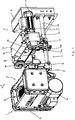
- FIG. 1 shows a perspective view of a trolley 1 of a bridge crane, not shown.
- a usual way horizontally extending support 2 (see FIG. 3 ), on which the trolley moves, and a load hook not shown.
- the trolley 1 is over a total of four wheels 3a, 3b, 3c and 3d, each with the same diameter along the carrier 2, in particular in the longitudinal direction, movable.
- the wheels 3a, 3b, 3c and 3d are arranged in the usual way from the top of the carrier 2 in the corners of an imaginary rectangle (see also FIG. 2 ).
- a first impeller 3a and a second impeller 3b are commonly driven by an electric traction motor 4.
- Impellers 3c and 3d are not driven and freely rotatable. All wheels 3a, 3b, 3c and 3d are rotatably mounted on a support frame 5 of the trolley 1 about horizontal and mutually parallel or aligned with each other axes. The axes are horizontal, assuming that the treads of the carrier 2 are horizontal.
- the inherently rigid support frame 5 of the trolley 1 is composed of several components, which are explained in more detail below.
- the support frame 5 In the direction of travel F of the trolley 1 and thus seen in the longitudinal direction of the carrier 2, the support frame 5 is U-shaped.
- the support frame 5 In order to store the four wheels 3a, 3b, 3c and 3d in a vehicle-like manner, the support frame 5 has four rectangular bearing brackets 5a, 5b, 5c and 5d, of which in each case the first and third bearing brackets 5a and 5c lying opposite each other with respect to the carrier 2 are connected to each other at their lower ends with a first cross member 6a and the opposite second and fourth bearing brackets 5b and 5d at their lower ends with a second cross member 6b (see FIG. 2 ) are connected.
- first and second longitudinal members 5e and 5f which extend in the direction of travel F of the trolley 1.
- first side member 5e connects the first and second bearing brackets 5a and 5b
- second side member 5f connects the third and fourth bearing brackets 5c and 5d.
- a arranged on the support frame 5 of the trolley 1 lifting 7 takes over the function of the second longitudinal member 5f.
- the first and second cross beams 6a and 6b are formed as tubes on which the first and second bearing brackets 5a and 5b are slidable and fixable to adjust the trolley 1 to the width of the beam 2 and to be mounted thereon.
- FIG. 1 can be seen that the first mounted on the first bearing bracket 5a impeller 3a is driven by an electric traction motor 4, which is flanged to the first impeller 3a opposite end of the first bearing bracket 5a via a driving gear 9.
- the axes of rotation of the drive motor 4 and the first impeller 3a are parallel to each other or aligned with each other.
- the movable by means of the trolley 1 in the direction of travel F and thus in the longitudinal direction of the carrier 2 hoist 7 consists in the usual way of an electric Lifting motor 7a, which acts on a cable drum 7c via a screw jack 7b and is preferably designed as a cable pull.
- the lifting mechanism 7 has a compact C-shaped form.
- the lifting motor 7a is disposed below the cable drum 7c, wherein the axes of rotation run parallel and in the direction of travel F.
- the screw jack 7b connects the lifting motor 7a and the cable drum 7c to each other at a rear end viewed in the direction of travel F.
- the carrier 2 is, for example, part of a bridge crane, the carrier 2 can be moved transversely to its longitudinal extension via traction drives arranged on the carrier 2 at both ends.
- the trolley 1 is additionally movable transversely to the longitudinal direction of the carrier 2 with the lifting mechanism 7 arranged thereon. This is a movement of the hoist in the longitudinal direction of the carrier 2 by means of the trolley 1, regardless of any additional possible movement transverse to the longitudinal direction of the carrier 2 by means of the possible drives for the carrier. 2
- the first impeller 3a and the second impeller 3b are drivingly connected to each other via a traction means 10.
- the traction means 10 is circumferentially guided around a first pulley 11a and a second pulley 11b, which are respectively associated with the first and second impellers 3a and 3b and have the same effective diameter.
- the traction means 10 is arranged outside the traction motor 4 and thus the drive motor 4 and the axis on which the driven first impeller 3a is mounted, drivingly connected downstream, so that the traction means 10 is driven by the corresponding axis.
- the traction means 10 thus does not drive the axis of the first impeller 3a, but it is driven by it.
- the traction means 10 drives by the drive connection thus only the axis on which the second impeller 3b is mounted.
- the first and second pulleys 11a and 11b may be supported on the axles of the first and second wheels 3a and 3b, and may thus be disposed adjacent to, or remote from, the wheels 3a and 3b or directly on the first and second wheels 3a and 3b be attached.
- the first and second traction pulleys 11a and 11b are each an integral part of the first and second impellers 3a and 3b.
- the traction means 10 is preferably formed as a V-ribbed belt and the first and second traction pulley 11a and 11b respectively as profiled V-ribbed pulleys.
- traction means 10 positive traction means such as timing belt and To use roller chains or friction traction means such as V-belts, flat belts and round belts.
- the first and second pulley discs 11a and 11b are then formed complementary to the respectively selected traction means 10.
- first and second cross beams 6a and 6b are extended beyond the first and third bearing brackets 5a and 5c to receive an electrical terminal box 8 at the end thereof opposite to the hoist gear 7.
- FIG. 1 a trolley is shown, which is designed as a so-called Einschienenkatze with a short height.
- This design is characterized by its compact and space-saving design.
- the lifting mechanism 7 seen in the direction of travel F is arranged laterally next to the carrier 2, so that the load hook 13 (see FIG. 3 ) can be raised as high as possible under the carrier 2.
- a comparable operating situation can arise due to a load hook hanging and swinging on the load hook.
- the first and second wheels 3a and 3b are respectively associated with pairs of resiliently biased friction rollers 12, which pull the first and second wheels 3a and 3b onto the carrier 2 serving as a running rail 2a.
- the axes of the four friction rollers 12 are aligned parallel to the axes of the four wheels 3a, 3b, 3c and 3d.
- Each of the four friction rollers 12 is pivotally mounted on the first cross member 6a and second cross member 6b via a lever 12a.
- the levers 12a of a pair of friction rollers 12 are held by a common adjustable spring element 12b in a prestressed v-shaped position, in which the friction rollers 12 are pressed from below on serving as a rail 2a carrier 2.
- the friction rollers 12 are arranged in front of and behind the respective first or second impeller 3a and 3b and arranged in the direction of travel F below the respective first or second impeller 3a and 3b. It is also possible to provide a counterweight instead of the friction rollers 12 and to balance the trolley 1 accordingly.
- FIG. 2 is a plan view of the trolley 1 according to FIG. 1 shown. For reasons of clarity, however, the traction means 10 between the first and second wheels 3a and 3b has not been shown. From this top view, the vehicle-like arrangement of the four wheels 3a, 3b, 3c and 3d in the vertices of an imaginary rectangle can be seen.
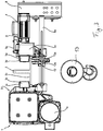
- FIG. 3 shows a front view of the trolley 1 according to FIG. 1 , in addition to the carrier 2 and a load hook 13 is located. For reasons of clarity, however, the hoisting rope has been omitted.
- the carrier 2 is designed as a double-T-carrier, the horizontal lower flange serves as a running rail 2a. On the running rail 2a, the wheels 3a, 3b, 3c and 3d roll off and at the bottom of the running rail 2a, the rolling rollers 12 rolling there are pressed.
- the carrier 2 may also be formed as a box girder, which has a cross section with opposite slide rails 2a for the wheels 3a, 3b, 3c and 3d and the friction rollers 12.
- FIG. 4 A detailed view of the trolley 1 according to FIG. 1 from the region of the traction means 10 is in FIG. 4 shown.
- the traction means 10 drives the second impeller 3b via the first impeller 3a. It goes without saying that an unillustrated and adjustable tensioning device for the traction means 10 must be present. For this a conceivable role is conceivable.
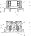
- the FIG. 5a shows a sectional view of the driving first impeller 3a.
- the impeller 3a has in a conventional manner a circumferential tread 3e, with which the trolley 1 is in contact on the support 2. Adjacent to the running surface 3e, specifically at its side facing the bearing bracket 5a, the traction sheave 11a in the form of a widened running surface 3e adjoins.
- a design of the traction device 10 as a V-ribbed belt corresponding v-shaped grooves are incorporated into the peripheral surface of the traction pulley 11a in a complementary configuration to the number and shape of the ribs on the V-ribbed belt.
- the first pulley 11a and the first impeller 3a are thus integrally formed.
- FIG. 5b is a sectional view of the driven second impeller 3b, which is one of the FIG. 5a corresponding embodiment of the second Pulley 11 b can be seen.
- the FIGS. 5a and 5b differ in the storage of the wheels 3a, 3b, since the first impeller 3a is driven via a motor shaft 4a and the second impeller 3b freely rotates about an axis 3f. Under motor shaft 4a here is the output shaft of the transmission 9 to understand.
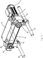
- FIG. 6 a perspective view of a trolley 1 of a crane in a second embodiment.
- This embodiment is substantially identical to the trolley 1 described above, so that the description of the FIGS. 1 to 3 Reference is made.
- This embodiment differs from that described above by the arrangement of the first and second pulley discs 11a, 11b on the rear side of the first and second bearing brackets 5a, 5b.
- the reverse side is understood to be the side of the bearing brackets 5a, 5b facing away from the carrier 2.
- the first and second pulley 11a, 11b are thus mounted on the motor shaft 4a and the axis 3f.
- first and second traction pulleys 11a, 11b are supported separately from the first and second wheels 3a, 3b on the motor shaft 4a and the shaft 3f.
- the traction means 10 thus runs on the back of the first longitudinal member 5e, the first and second bearing brackets 5a, 5b and is thus protected from any contamination caused by the method of the trolley 1 on the support 2.
- FIG. 7 shows a perspective view of a trolley 1 in a third embodiment of a hoist designed as a chain hoist, which is not shown for reasons of clarity.
- the design of the trolley 1 is comparable with respect to the essential components with the two trolleys 1 described above.
- the essential difference lies in a shorter wheelbase of the four wheels 3a, 3b, 3c and 3d, of which only the first and second wheels 3a, 3b is visible.
- the opposing third and fourth wheels 3c, 3d are covered by the serving as a rail 2a carrier 2.
- the first and second side parts 5g, 5h are used to support the four wheels 3a, 3b, 3c and 3d and are connected via a single tubular or rod-shaped cross member 6a at their lower ends to the U-shaped support frame 5.
- Trolley 1 shown is also referred to as Unterflanschfahrtechnik, since the four wheels 3a, 3b, 3c and 3d roll on serving as a running rail 2a lower flange of the carrier 2. Centered on the cross member 6a then the chain hoist is suspended, which is movable over the trolley 1 along the carrier.
- the first and second wheels 3a, 3b are driven in common via an electric traction motor 4.
- the traction motor 4 is drivingly connected to the first impeller 3a through a gear 9 flanged to the right side member 5g.
- a first and a second pulley 11a, 11b are arranged on the back of the first side part 5g, which are connected via respective shafts with the on the opposite side of the first side part 5g arranged first and second wheels 3a, 3b drivingly connected.
- the first and the second pulley 11a, 11b are drivingly connected to each other via a circulating and designed as a toothed belt 10 traction means.
- a cover for the traction means 10 and the Switzerlandstoffierin 11a, 11b have been omitted. This cover is arranged between the first side part 5g and the transmission 9.
- the present invention generally for use in trolleys 1 for hoists of any kind and not only for the above-described single-rail cat in a short design and chain hoists.
Landscapes
- Engineering & Computer Science (AREA)
- Mechanical Engineering (AREA)
- Carriers, Traveling Bodies, And Overhead Traveling Cranes (AREA)
- Handcart (AREA)
Description
- Der Erfindung betrifft eine Laufkatze für ein Hebezeug, mit einem an einem Tragrahmen angeordneten Hubwerk, mit an dem Tragrahmen gelagerten Laufrädern, über die die Laufkatze an einem Träger verfahrbar ist und von denen mindestens ein erstes Laufrad auf einer Achse gelagert ist und die Achse gemeinsam mit dem Laufrad mittels eines Fahrmotors antreibbar ist.
- Aus der deutschen Offenlegungsschrift
DE 103 45 102 A1 ist eine Laufkatze eines Krans bekannt, die über insgesamt vier Laufräder auf und entlang einer Trägers verfahrbar ist. Die Laufräder sind in üblicher Weise von oben auf den Träger gesehen in den Ecken eines gedachten Rechtecks angeordnet. Eines der vier Laufrädern ist elektrisch angetrieben. Um die Antriebskräfte des angetriebenen Laufrads sicher auf den Träger, der auch als Fahrschiene dient, zu übertragen, ist ein Paar von federnd vorgespannten Reibrollen vorgesehen, über die das angetriebene Laufrad auf die Fahrschiene gezogen wird. Alternativ ist dort beschrieben, dass mehrere der Laufräder über den einen Fahrantrieb oder jeweils separate Fahrantriebe angetrieben werden können. - Die deutsche Offenlegungsschrift
DE 1 803 471 A offenbart einen Kran auf dessen Förderwagen eine Laufkatze verfahrbar ist, die mittels eines Linearmotors angetrieben wird. Der bewegte Teil des Linearmotors umfasst ein als Band oder Kette ausgebildetes Zugmittel, das von dem durch Induktionsspulen gebildeten stationären Teil des Linearmotors angetrieben wird. Über das Zugmittel des Linearmotors werden zwei Radachsen gemeinsam mit beidendig auf jeder Radachse angeordneten Laufrädern angetrieben. Das Zugmittel ist Teil des Linearmotors und den beiden Radachsen antriebsmäßig vorgeschaltet, so dass beide Radachsen gemeinsam von dem Zugmittel angetrieben werden. - In der
FR 1 360 309 A - Aus der deutschen Offenlegungsschrift
DE 10 2010 041 894 A1 ist zudem eine Fördervorrichtung mit einer Laufkatze bekannt, deren Fahrantrieb ein Riemengetriebe aufweist. - Der vorliegenden Erfindung liegt die Aufgabe zugrunde, eine Laufkatze eines Kran zu schaffen, die eine zuverlässige Übertragung der Antriebskräfte zwischen Laufrad und Fahrschiene gewährleistet.
- Die Aufgabe wird durch eine Laufkatze eines Krans mit den Merkmalen des Anspruchs 1 gelöst. Vorteilhafte Ausgestaltungen der Erfindung sind in den Ansprüchen 2 bis 9 angegeben.
- Erfindungsgemäß wird bei einer Laufkatze für ein Hebezeug, mit einem an einem Tragrahmen angeordneten Hubwerk, mit an dem Tragrahmen gelagerten Laufrädern, über die die Laufkatze an einem Träger verfahrbar ist und von denen mindestens ein erstes Laufrad auf einer Achse gelagert ist und die Achse gemeinsam mit dem Laufrad mittels eines Fahrmotors antreibbar ist, wobei das antreibbare erste Laufrad eine umlaufende Lauffläche aufweist und die Lauffläche derart ausgebildet und angeordnet ist, dass sie beim Verfahren der Laufkatze an dem Träger mit dem Träger in Kontakt steht, eine zuverlässige Übertragung der Antriebskräfte zwischen Laufrad und Fahrschiene dadurch gewährleistet, dass das antreibbare erste Laufrad mit mindestens einem der weiteren Laufräder über ein Zugmittel derart antriebsmäßig miteinander verbunden ist, dass die Achse zwischen dem Fahrmotor und dem Zugmittel angeordnet und damit das Zugmittel der Achse antriebsmäßig nachgeschaltet ist, so dass das Zugmittel von der Achse angetrieben werden kann, und die Lauffläche beim Verfahren der Laufkatze an dem Träger außerhalb des Zugmittels mit dem Träger in Kontakt steht. Diese Ausgestaltung hat einen einfachen konstruktiven Aufbau und ermöglicht auch bei relativ großen Abständen der Laufräder, diese einfach antriebsmäßig zu verbinden und die entsprechenden Antriebskräfte zu übertragen. Auch beugt das Zugmittel, wenn dieses reibschlüssig ausgebildet ist, etwaigen Überlastungen des Fahrwerks vor, da dieses bei Überlast einfach durchrutscht. Durch den Antrieb der Laufkatze über mindestens zwei Laufrädern werden die Antriebskräfte sicherer auf die Fahrschiene übertragen. Somit kann eine gleichmäßige Bewegung der Laufkatze auch unter rauen Betriebssituationen erreicht werden. Auch wird ein Durchrutschen der Laufräder und somit deren Verschleiß minimiert. Ferner erhöht das Zugmittel die Laufruhe der angetriebenen Laufräder.
- Konstruktiv besonders einfach ist der Einsatz des Zugmittels, wenn das angetriebene erste Laufrad und das mindestens eine der weiteren Laufräder in Fahrtrichtung der Laufkatze gesehen hintereinander und auf einer gemeinsamen Seite des Trägers angeordnet sind.
- Vorzugsweise ist vorgesehen, dass von dem angetriebenen ersten Laufrad über das Zugmittel das zweite Laufrad antreibbar ist. Hierdurch wird für die überwiegenden Betriebsfälle eine ausreichende Traktion erreicht.
- In bevorzugter Ausgestaltung ist das Zugmittel als Keilrippenriemen ausgebildet. Der Keilrippenriemen ermöglicht eine sichere und schlupfarme Übertragung der Antriebskräfte.
- In konstruktiver Hinsicht ist vorgesehen, dass den angetriebenen Laufrädern antriebsmäßig jeweils eine Zugmittelscheibe zugeordnet ist und das Zugmittel um die Zugmittelscheiben umläuft.
- Eine besonders kompakte und einfache Bauweise ergibt sich dadurch, dass die angetriebenen Laufräder und die zugehörige Zugmittelscheibe jeweils einteilig ausgebildet sind. Hierbei ist besonders vorteilhaft, dass die Zugmittelscheibe jeweils an die Lauffläche der angetriebenen Laufrädern angrenzt.
- In einer alternativen Ausgestaltung ist vorgesehen, dass die angetriebenen Laufräder und die zugehörige Zugmittelscheibe jeweils über eine Motorwelle beziehungsweise eine Achse antriebsmäßig miteinander verbunden sind. Das Zugmittel verläuft somit auf der Rückseite des ersten Längsträger und somit auf dessen von dem Träger abgewandten Seite. Hierdurch ist der Zugmitteltrieb geschützt vor etwaigen Verschmutzungen die durch das Verfahren der Laufkatze auf dem Träger entstehen.
- Um die Traktion der angetriebenen Laufräder zu erhöhen, sind diese über federnd vorgespannte Reibrollen in Richtung des als Fahrschiene dienenden Trägers beaufschlagt.
- Nachfolgend wird die Erfindung anhand von mehreren Ausführungsbeispielen, die in einer Zeichnung dargestellt sind, näher erläutert. Es zeigen:
-
Figur 1 eine perspektivische Ansicht einer Laufkatze eines Krans, -
Figur 2 eine Draufsicht auf die Laufkatze gemäßFigur 1 jedoch ohne Zugmittel, -
Figur 3 eine Vorderansicht der Laufkatze gemäßFigur 1 , -
Figur 4 eine Detailansicht der Laufkatze gemäßFigur 1 , -
Figur 5a eine Schnittansicht eines antreibenden Laufrads, -
Figur 5b eine Schnittansicht eines angetriebenen Laufrads, -
Figur 6 eine perspektivische Ansicht einer Laufkatze eines Krans in einer zweiten Ausführungsform und -
Figur 7 eine perspektivische Ansicht einer Laufkatze in einer dritten Ausführungsform für ein als Kettenzug ausgebildetes Hebezeug. - Die
Figur 1 zeigt eine perspektivische Ansicht einer Laufkatze 1 eines nicht dargestellten Brückenkrans. Aus Gründen der Übersichtlichkeit sind ein üblicher Weise horizontal verlaufender Träger 2 (sieheFigur 3 ), auf dem die Laufkatze verfährt, und ein Lasthaken nicht dargestellt. Die Laufkatze 1 ist über insgesamt vier Laufräder 3a, 3b, 3c und 3d mit jeweils gleichem Durchmesser entlang des Trägers 2, insbesondere in dessen Längsrichtung, verfahrbar. Die Laufräder 3a, 3b, 3c und 3d sind in üblicher Weise von oben auf den Träger 2 gesehen in den Ecken eines gedachten Rechtecks angeordnet (siehe auchFigur 2 ). Von den vier Laufrädern 3a, 3b, 3c und 3d sind ein erstes Laufrad 3a und ein zweites Laufrad 3b gemeinsam über einen elektrischen Fahrmotor 4 angetrieben. In Fahrtrichtung F der Laufkatze 1 und damit in Längsrichtung des Trägers 2 gesehen sind das erste Laufrad 3a und das zweite Laufrad 3b mit Abstand zueinander und hintereinander angeordnet. Die jeweils dem ersten und zweiten Laufrad 3a und 3b gegenüber liegenden dritten und vierten Laufräder 3c und 3d sind nicht angetrieben und frei drehbar. Alle Laufräder 3a, 3b, 3c und 3d sind an einem Tragrahmen 5 der Laufkatze 1 um horizontale und zueinander parallele beziehungsweise mit einander fluchtende Achsen drehbar gelagert. Die Achsen verlaufen horizontal unter der Annahme, dass die Laufflächen des Trägers 2 horizontal verlaufen. - Der in sich biegesteife Tragrahmen 5 der Laufkatze 1 setzt sich aus mehreren Bauteilen zusammen, die nachfolgend näher erläutert werden. In Fahrtrichtung F der Laufkatze 1 und somit in Längsrichtung des Trägers 2 gesehen ist der Tragrahmen 5 u-förmig ausgebildet. Um die vier Laufräder 3a, 3b, 3c und 3d fahrzeugartig zu lagern, weist der Tragrahmen 5 vier quaderförmige Lagerkonsolen 5a, 5b, 5c und 5d auf, von denen jeweils die in Bezug auf den Träger 2 gegenüber liegenden ersten und dritten Lagerkonsolen 5a und 5c an ihren unteren Enden mit einem ersten Querträger 6a untereinander verbunden sind und die gegenüber liegenden zweiten und vierten Lagerkonsolen 5b und 5d an ihren unteren Enden mit einem zweiten Querträger 6b (siehe
Figur 2 ) verbunden sind. Die somit entstehenden beiden u-förmigen vorderen und hinteren Lagerteile sind dann über erste und zweite Längsträger 5e und 5f, die sich In Fahrtrichtung F der Laufkatze 1 erstrecken, zu dem Tragrahmen 5 verbunden. Hierbei verbindet der erste Längsträger 5e die erste und zweite Lagerkonsole 5a und 5b sowie der zweite Längsträger 5f die dritte und vierte Lagerkonsole 5c und 5d. Im vorliegenden Ausführungsbeispiel übernimmt ein an dem Tragrahmen 5 der Laufkatze 1 angeordnetes Hubwerk 7 die Funktion des zweiten Längsträgers 5f. Die ersten und zweiten Querträger 6a und 6b sind als Rohre ausgebildet, an denen die die erste und zweite Lagerkonsole 5a und 5b verschiebbar und festlegbar sind, um die Laufkatze 1 an die Breite des Trägers 2 anzupassen und an diesem zu montieren. - Des Weiteren ist der
Figur 1 zu entnehmen, dass das erste an der ersten Lagerkonsole 5a gelagerte Laufrad 3a über einen elektrischen Fahrmotor 4 angetrieben ist, der an dem dem ersten Laufrad 3a gegenüberliegenden Ende der ersten Lagerkonsole 5a über eine Fahrgetriebe 9 angeflanscht ist. Die Drehachsen des Fahrmotors 4 und des ersten Laufrads 3a verlaufen parallel zueinander oder fluchten miteinander. - Das mittels der Laufkatze 1 in deren Fahrtrichtung F und damit in Längsrichtung des Trägers 2 verfahrbare Hubwerk 7 besteht in üblicher Weise aus einem elektrischen Hubmotor 7a, der über ein Hubgetriebe 7b auf eine Seiltrommel 7c wirkt und ist vorzugsweise als Seilzug ausgebildet. Insgesamt weist das Hubwerk 7 eine kompakte c-förmige Form auf. Hierbei ist der Hubmotor 7a unterhalb der Seiltrommel 7c angeordnet, wobei deren Drehachsen parallel und in Fahrtrichtung F verlaufen. Das Hubgetriebe 7b verbindet Hubmotor 7a und Seiltrommel 7c an einem in Fahrrichtung F gesehen hinteren Ende miteinander. Sofern der Träger 2 beispielsweise Teil eines Brückenkrans ist, kann der Träger 2 über beidendig an dem Träger 2 angeordnete Fahrantriebe quer zu seiner Längserstreckung verfahren werden. Dadurch ist dann die Laufkatze 1 mit dem hieran angeordneten Hubwerk 7 zusätzlich auch quer zur Längsrichtung des Trägers 2 bewegbar. Damit ist eine Bewegung des Hubwerks in Längsrichtung des Trägers 2 mittels der Laufkatze 1 unabhängig von einer eventuell zusätzlich möglichen Bewegung quer zur Längsrichtung des Trägers 2 mittels der etwaigen Fahrantriebe für den Träger 2.
- Um neben dem ersten Laufrad 3a auch das zweite Laufrad 3b anzutreiben, sind das erste Laufrad 3a und das zweite Laufrad 3b über ein Zugmittel 10 antriebsmäßig miteinander verbunden. Das Zugmittel 10 ist umlaufend um eine erste Zugmittelscheibe 11a und eine zweite Zugmittelscheibe 11b geführt, die jeweils dem ersten und zweiten Laufrad 3a und 3b zugeordnet sind und den gleichen wirksamen Durchmesser haben. Mit anderen Worten ist das Zugmittel 10 außerhalb des Fahrmotors 4 angeordnet und somit dem Fahrmotor 4 sowie der Achse, auf der das angetriebene erste Laufrad 3a gelagert ist, antriebsmäßig nachgeschaltet, so dass das Zugmittel 10 von der entsprechenden Achse angetrieben wird. Das Zugmittel 10 treibt also nicht die Achse des ersten Laufrads 3a an, sondern es wird hiervon angetrieben. Das Zugmittel 10 treibt durch die antriebsmäßige Verbindung somit lediglich die Achse an, auf der das zweite Laufrad 3b gelagert ist. Die erste und zweite Zugmittelscheibe 11a und 11b können an den Achsen der ersten und das zweiten Laufräder 3a und 3b gelagert sein und somit angrenzend zu den Laufrädern 3a und 3b oder entfernt zu diesen angeordnet sein oder direkt an den ersten und das zweiten Laufräder 3a und 3b befestigt sein. In dem gezeigten Ausführungsbeispiel sind jeweils die erste und zweite Zugmittelscheibe 11a und 11b integraler Bestandteil des ersten beziehungsweise des zweiten Laufrades 3a und 3b. Das Zugmittel 10 ist vorzugsweise als Keilrippenriemen und die erste und zweite Zugmittelscheibe 11a und 11b entsprechend als profilierte Keilrippenriemenscheiben ausgebildet. Es ist auch denkbar, als Zugmittel 10 formschlüssige Zugmittel wie Zahnriemen und Rollenketten oder reibschlüssige Zugmittel wie Keilriemen, Flachriemen und Rundriemen einzusetzen. Die erste und zweite Zugmittelscheibe 11a und 11b sind dann komplementär zu dem jeweils gewählten Zugmittel 10 ausgebildet.
- Auch sind die ersten und zweiten Querträger 6a und 6b über die erste und dritte Lagerkonsole 5a und 5c hinaus verlängert, um an deren Ende, das dem Hubwerk 7 gegenüber liegt, einen elektrischen Anschlusskasten 8 aufzunehmen.
- In der
Figur 1 ist eine Laufkatze gezeigt, die als sogenannte Einschienenkatze mit kurzer Bauhöhe ausgebildet ist. Diese Bauform zeichnet sich durch ihre kompakte und Platz sparende Bauweise aus. Hierbei ist das Hubwerk 7 in Fahrtrichtung F gesehen seitlich neben dem Träger 2 angeordnet, so dass der Lasthaken 13 (sieheFigur 3 ) möglichst hoch unter den Träger 2 angehoben werden kann. Hieraus ergibt sich bezogen auf die Mitte des Trägers 2 eine seitliche Verlagerung des Masse-Schwerpunktes des Hubwerks 7. Hierdurch besteht beim Verfahren der Laufkatze 1 ohne Nutzlast die Gefahr, dass die angetriebenen ersten und zweiten Laufräder 3a und 3b, die dem Hubwerk 7 gegenüber liegen, entlastet werden, abheben und/oder durchrutschen. Eine vergleichbare Betriebssituation kann durch eine am Lasthaken hängende und schwingende Last entstehen. Um das Entlasten, Abheben und Durchrutschen zu vermeiden, sind den ersten und zweiten Laufrädern 3a und 3b jeweils Paare von federnd vorgespannten Reibrollen 12 zugeordnet, die die ersten und zweiten Laufräder 3a und 3b auf den als Fahrschiene 2a dienenden Träger 2 ziehen. Die Achsen der vier Reibrollen 12 sind parallel zu den Achsen der vier Laufräder 3a, 3b, 3c und 3d ausgerichtet. Jede der insgesamt vier Reibrollen 12 ist über einen Hebel 12a schwenkbar an dem ersten Querträger 6a beziehungsweise zweiten Querträger 6b gelagert. Die Hebel 12a eines Paares der Reibrollen 12 werden über ein gemeinsames einstellbares Federelement 12b in einer vorgespannten v-förmigen Stellung gehalten, in der die Reibrollen 12 von unten an den als Fahrschiene 2a dienenden Träger 2 angedrückt werden. Hierbei sind quer zur Fahrtrichtung F gesehen die Reibrollen 12 vor und hinter des jeweiligen ersten oder zweiten Laufrades 3a und 3b angeordnet und in Fahrtrichtung F gesehen unterhalb des jeweiligen ersten oder zweiten Laufrades 3a und 3b angeordnet. Auch ist es möglich, anstatt der Reibrollen 12 ein Gegengewicht vorzusehen und die Laufkatze 1 entsprechend hiermit auszubalancieren. - In der
Figur 2 ist eine Draufsicht auf die Laufkatze 1 gemäßFigur 1 gezeigt. Aus Gründen der Übersichtlichkeit ist jedoch das Zugmittel 10 zwischen den ersten und zweiten Laufrädern 3a und 3b nicht dargestellt worden. Aus dieser Draufsicht ist die fahrzeugartige Anordnung der vier Laufräder 3a, 3b, 3c und 3d in den Eckpunkten eines gedachten Rechtecks ersichtlich. - Die
Figur 3 zeigt eine Vorderansicht der Laufkatze 1 gemäßFigur 1 , in die zusätzlich der Träger 2 und ein Lasthaken 13 eingezeichnet ist. Aus Gründen der Übersichtlichkeit ist jedoch das Hubseil weggelassen worden. Der Träger 2 ist als Doppel-T-Träger ausgebildet, dessen horizontaler Unterflansch als Fahrschiene 2a dient. Auf der Fahrschiene 2a rollen die Laufräder 3a, 3b, 3c und 3d ab und unten an der Fahrschiene 2a werden die dort abrollenden Reibrollen 12 angepresst. Der Träger 2 kann auch als Kastenträger ausgebildet sein, der einen Querschnitt mit gegenüberliegenden Fahrschienen 2a für die Laufräder 3a, 3b, 3c und 3d und die Reibrollen 12 aufweist. - Eine Detailansicht der Laufkatze 1 gemäß
Figur 1 aus dem Bereich des Zugmittels 10 ist inFigur 4 dargestellt. Das Zugmittel 10 treibt über das erste Laufrad 3a das zweite Laufrad 3b an. Es ist selbstverständlich, dass eine nicht dargestellte und einstellbare Spannvorrichtung für das Zugmittel 10 vorhanden sein muss. Hierfür ist eine anstellbare Rolle denkbar. - Die
Figur 5a zeigt eine Schnittansicht des antreibenden ersten Laufrads 3a. Das Laufrad 3a weist in üblicher Weise eine umlaufende Lauffläche 3e auf, mit der die Laufkatze 1 auf dem Träger 2 in Kontakt steht. Angrenzend zu der Lauffläche 3e und zwar an deren der Lagerkonsole 5a zugewandten Seite schließt sich die Zugmittelscheibe 11a in Form einer verbreiterten Lauffläche 3e an. Bei einer Ausbildung des Zugmittels 10 als Keilrippenriemen sind in komplementärer Ausgestaltung zu der Anzahl und Form der Rippen an dem Keilrippenriemen entsprechende v-förmige Nuten in die Umfangsfläche der Zugmittelscheibe 11a eingearbeitet. Die erste Zugmittelscheibe 11a und das erste Laufrad 3a sind somit einteilig ausgebildet. - In der
Figur 5b ist eine Schnittansicht des angetriebenen zweiten Laufrads 3b dargestellt, der eine derFigur 5a entsprechende Ausgestaltung der zweiten Zugmittelscheibe 11b zu entnehmen ist. DieFiguren 5a und 5b unterscheiden sich in der Lagerung der Laufräder 3a, 3b, da das erste Laufrad 3a über eine Motorwelle 4a angetrieben ist und das zweite Laufrad 3b frei um eine Achse 3f umläuft. Unter Motorwelle 4a ist hier die Ausgangswelle des Getriebes 9 zu verstehen. - Die
Figur 6 eine perspektivische Ansicht einer Laufkatze 1 eines Krans in einer zweiten Ausführungsform. Diese Ausführungsform stimmt im Wesentlichen mit der zuvor beschriebenen Laufkatze 1 überein, so dass auf die Beschreibung zu denFiguren 1 bis 3 Bezug genommen wird. Diese Ausführungsform unterscheidet sich von der zuvor beschriebenen durch die Anordnung der ersten und zweiten Zugmittelscheibe 11a, 11b auf der Rückseite der ersten und zweiten Lagerkonsole 5a, 5b. Als Rückseite wird hierbei die von dem Träger 2 abgewandte Seite der Lagerkonsolen 5a, 5b verstanden. Die ersten und zweiten Zugmittelscheibe 11a, 11b sind somit auf der Motorwelle 4a und der Achse 3f gelagert. Entsprechend sind die ersten und zweiten Zugmittelscheiben 11a, 11b von den ersten und zweiten Laufrädern 3a, 3b getrennt auf der Motorwelle 4a und der Achse 3f gelagert. Das Zugmittel 10 verläuft somit auf der Rückseite des ersten Längsträgers 5e, der ersten und zweiten Lagerkonsole 5a, 5b und ist somit geschützt vor etwaigen Verschmutzungen die durch das Verfahren der Laufkatze 1 auf dem Träger 2 entstehen. - Die
Figur 7 zeigt eine perspektivische Ansicht einer Laufkatze 1 in einer dritten Ausführungsform für ein als Kettenzug ausgebildetes Hebezeug, das aus Gründen der Übersichtlichkeit nicht dargestellt ist. Die Ausgestaltung der Laufkatze 1 ist in Bezug auf die wesentlichen Bauteile vergleichbar mit den beiden zuvor beschriebenen Laufkatzen 1. Der wesentliche Unterschied liegt in einem kürzeren Radstand der vier Laufräder 3a, 3b, 3c und 3d, von denen nur das erste und zweite Laufrad 3a, 3b sichtbar ist. Die gegenüber liegenden dritten und vierten Laufräder 3c, 3d sind von dem als Fahrschiene 2a dienendem Träger 2 verdeckt. Durch den kurzen Radstand ist auch eine kompaktere Gestaltung des Tragrahmens 5 möglich, der in Fahrtrichtung F gesehen auf der rechten Seite des Trägers 2 anstatt einer ersten Lagerkonsole, einer zweiten Lagerkonsole und einem ersten Längsträger ein erstes Seitenteil 5g und in Fahrtrichtung F gesehen auf der linken Seite des Trägers 2 anstatt einer dritten Lagerkonsole, einer vierten Lagerkonsole und einem zweiten Längsträger ein zweites Seitenteil 5h aufweist. Die ersten und zweiten Seitenteile 5g, 5h dienen zur Lagerung der vier Laufräder 3a, 3b, 3c und 3d und sind über einen einzigen rohr- bzw. stangenförmigen Querträger 6a an ihren unteren Enden zu dem u-förmigen Tragrahmen 5 verbunden. Die in derFigur 6 gezeigte Laufkatze 1 wird auch als Unterflanschfahrwerk bezeichnet, da deren vier Laufräder 3a, 3b, 3c und 3d auf dem als Fahrschiene 2a dienenden Unterflansch des Trägers 2 abrollen. Mittig an dem Querträger 6a ist dann der Kettenzug aufgehängt, der über die Laufkatze 1 entlang des Trägers verfahrbar ist. - Auch bei dieser dritten Ausführungsform sind das erste und zweite Laufrad 3a, 3b gemeinsam über einen elektrischen Fahrmotor 4 angetrieben. Der Fahrmotor 4 ist über ein Getriebe 9, das an dem rechten Seitenteil 5g angeflanscht ist, antriebsmäßig mit dem ersten Laufrad 3a verbunden. Entsprechend der zweiten Ausführungsform sind auf der Rückseite des ersten Seitenteils 5g eine erste und eine zweite Zugmittelscheibe 11a, 11b angeordnet, die über entsprechende Wellen mit den auf der gegenüber liegenden Seite des ersten Seitenteils 5g angeordnete erste und zweite Laufräder 3a, 3b antriebsmäßig verbunden sind. Auch hier sind die erste und die zweite Zugmittelscheibe 11a, 11b über ein umlaufendes und als Zahnriemen ausgebildetes Zugmittel 10 antriebsmäßig miteinander verbunden. Aus Gründen der Übersichtlichkeit ist in der
Figur 7 eine Abdeckung für das Zugmittel 10 und die Zugmittelscheiben 11a, 11b weggelassen worden. Diese Abdeckung ist zwischen dem ersten Seitenteil 5g und dem Getriebe 9 angeordnet. - Die vorliegende Erfindung allgemein für einen Einsatz bei Laufkatzen 1 für Hebezeuge jeder Art und nicht nur für die vorbeschriebene Einschienenkatze in kurzer Bauform und Kettenzüge.
-
- 1
- Laufkatze
- 2
- Träger
- 2a
- Fahrschiene
- 3a
- erstes Laufrad
- 3b
- zweites Laufrad
- 3c
- drittes Laufrad
- 3d
- viertes Laufrad
- 3e
- Lauffläche
- 3f
- Achse
- 4
- elektrischer Fahrmotor
- 4a
- Motorwelle
- 5
- Tragrahmen
- 5a
- erste Lagerkonsole
- 5b
- zweite Lagerkonsole
- 5c
- dritte Lagerkonsole
- 5d
- vierte Lagerkonsole
- 5e
- erster Längsträger
- 5f
- zweiter Längsträger
- 5g
- erstes Seitenteil
- 5h
- zweites Seitenteil
- 6a
- erster Querträger
- 6b
- zweiter Querträger
- 7
- Hubwerk
- 7a
- Hubmotor
- 7b
- Hubgetriebe
- 7c
- Seiltrommel
- 8
- elektrischer Anschlusskasten
- 9
- Fahrgetriebe
- 10
- Zugmittel
- 11a
- erste Zugmittelscheibe
- 11b
- zweite Zugmittelscheibe
- 12
- Reibrollen
- 12a
- Hebel
- 12b
- Federelement
- 13
- Lasthaken
- F
- Fahrtrichtung
Claims (9)
- Laufkatze (1) für ein Hebezeug, mit einem an einem Tragrahmen (5) angeordneten Hubwerk (7), mit an dem Tragrahmen (5) gelagerten Laufrädern (3a, 3b, 3c, 3d), über die die Laufkatze (1) an einem Träger (2) verfahrbar ist und von denen mindestens ein erstes Laufrad (3a) auf einer Achse gelagert ist und die Achse gemeinsam mit dem Laufrad (3a) mittels eines Fahrmotors (4) antreibbar ist, wobei das antreibbare erste Laufrad (3a) eine umlaufende Lauffläche (3e) aufweist und die Lauffläche (3e) derart ausgebildet und angeordnet ist, dass sie beim Verfahren der Laufkatze (1) an dem Träger (2) mit dem Träger (2) in Kontakt steht, dadurch gekennzeichnet, dass das antreibbare erste Laufrad (3a) derart mit mindestens einem der weiteren Laufräder (3b, 3c, 3d) über ein Zugmittel (10) antriebsmäßig miteinander verbunden ist, dass die Achse zwischen dem Fahrmotor (4) und dem Zugmittel (10) angeordnet und damit das Zugmittel (10) der Achse antriebsmäßig nachgeschaltet ist, so dass das Zugmittel (10) von der Achse angetrieben werden kann, und die Lauffläche (3e) beim Verfahren der Laufkatze (1) an dem Träger (2) außerhalb des Zugmittels (10) mit dem Träger (2) in Kontakt steht.
- Laufkatze (1) nach Anspruch 1, dadurch gekennzeichnet, dass das angetriebene erste Laufrad (3a) und das mindestens eine der weiteren Laufräder (3a, 3b, 3c, 3d) in Fahrtrichtung (F) der Laufkatze (1) gesehen hintereinander und auf einer gemeinsamen Seite der Träger (2) angeordnet sind.
- Laufkatze (1) nach Anspruch 1 oder 2, dadurch gekennzeichnet, dass von dem angetriebenen ersten Laufrad (3a) über das Zugmittel (10) das zweite Laufrad (3b) antreibbar ist.
- Laufkatze (1) nach einem der Ansprüche 1 bis 3, dadurch gekennzeichnet, dass das Zugmittel (10) als Keilrippenriemen ausgebildet ist.
- Laufkatze (1) nach einem der Ansprüche 1 bis 4, dadurch gekennzeichnet, dass den angetriebenen Laufrädern (3a, 3b, 3c, 3d) antriebsmäßig jeweils eine Zugmittelscheibe (11a, 11b) zugeordnet ist und das Zugmittel (10) um die Zugmittelscheiben (11a, 11b) umläuft.
- Laufkatze (1) nach Anspruch 5, dadurch gekennzeichnet, dass die angetriebenen Laufräder (3a, 3b, 3c, 3d) und die zugehörige Zugmittelscheibe (11a, 11b) jeweils einteilig ausgebildet sind.
- Laufkatze (1) nach Anspruch 6, dadurch gekennzeichnet, dass die Zugmittelscheibe (11a, 11b) jeweils an die Lauffläche (3e) der angetriebenen Laufräder (3a, 3b, 3c, 3d) angrenzt.
- Laufkatze (1) nach Anspruch 5, dadurch gekennzeichnet, dass die angetriebenen Laufräder (3a, 3b, 3c, 3d) und die zugehörige Zugmittelscheibe (11a, 11b) jeweils über eine Motorwelle (4a) beziehungsweise eine Achse (3f) antriebsmäßig miteinander verbunden sind.
- Laufkatze (1) nach einem der Ansprüche 1 bis 8, dadurch gekennzeichnet, dass die angetriebenen Laufräder (3a, 3b, 3c, 3d) über federnd vorgespannte Reibrollen (12) in Richtung des als Fahrschiene dienenden Trägers (2) beaufschlagt sind.
Applications Claiming Priority (2)
| Application Number | Priority Date | Filing Date | Title |
|---|---|---|---|
| DE102014117561.1A DE102014117561A1 (de) | 2014-11-28 | 2014-11-28 | Laufkatze für ein Hebezeug |
| PCT/EP2015/077930 WO2016083579A1 (de) | 2014-11-28 | 2015-11-27 | Laufkatze für ein hebezeug |
Publications (2)
| Publication Number | Publication Date |
|---|---|
| EP3224192A1 EP3224192A1 (de) | 2017-10-04 |
| EP3224192B1 true EP3224192B1 (de) | 2019-04-10 |
Family
ID=54313358
Family Applications (1)
| Application Number | Title | Priority Date | Filing Date |
|---|---|---|---|
| EP15804715.9A Active EP3224192B1 (de) | 2014-11-28 | 2015-11-27 | Laufkatze für ein hebezeug |
Country Status (13)
| Country | Link |
|---|---|
| US (1) | US10597263B2 (de) |
| EP (1) | EP3224192B1 (de) |
| JP (1) | JP6770956B2 (de) |
| KR (1) | KR102469817B1 (de) |
| CN (2) | CN204714349U (de) |
| AU (1) | AU2015352400B2 (de) |
| BR (1) | BR112017004219B1 (de) |
| CA (1) | CA2963614C (de) |
| DE (1) | DE102014117561A1 (de) |
| ES (1) | ES2731781T3 (de) |
| MX (1) | MX377608B (de) |
| RU (1) | RU2672309C1 (de) |
| WO (1) | WO2016083579A1 (de) |
Families Citing this family (3)
| Publication number | Priority date | Publication date | Assignee | Title |
|---|---|---|---|---|
| FI127757B (fi) * | 2017-09-22 | 2019-02-15 | Konecranes Global Oy | Nosturin nostovaunu |
| CN108750982A (zh) * | 2018-05-17 | 2018-11-06 | 四川攀登科技有限公司 | 轻量化塔机起升机构 |
| CN115676614A (zh) * | 2022-09-26 | 2023-02-03 | 航核研创智能设备科技(无锡)有限公司 | 一种移动式电随动行车 |
Family Cites Families (27)
| Publication number | Priority date | Publication date | Assignee | Title |
|---|---|---|---|---|
| US2861850A (en) * | 1956-03-16 | 1958-11-25 | Abell Howe Company | Wheel and axle assembly |
| US2997966A (en) * | 1958-12-08 | 1961-08-29 | Manning Maxwell & Moore Inc | Crane bridge |
| DE1803471U (de) * | 1959-03-25 | 1959-12-31 | Christof Rahnhoefer O H G | Spielzeug-scherzartikel. |
| FR1360309A (fr) * | 1963-03-27 | 1964-05-08 | Mac Gregor Comarain Sa | Dispositif de manutention tel qu'un pont roulant ou analogue |
| GB1185929A (en) * | 1967-10-19 | 1970-03-25 | Morris Ltd Herbert | Improvements in Drives for Cranes, Hoists and Travelling Trolleys |
| JPS56170185U (de) * | 1980-05-19 | 1981-12-16 | ||
| FR2642029B1 (fr) * | 1988-12-29 | 1991-05-03 | Ipr Productique Sarl | Dispositif de deplacement et de guidage en translation d'un mobile |
| JPH05193559A (ja) * | 1991-06-27 | 1993-08-03 | Yamaha Motor Co Ltd | 自走船台 |
| US6371031B1 (en) | 2000-11-21 | 2002-04-16 | Spacesaver Corporation | Mobile carriage |
| JP3996255B2 (ja) * | 1998-02-09 | 2007-10-24 | ヤマハ発動機株式会社 | 電動二輪車 |
| JP2004017745A (ja) * | 2002-06-14 | 2004-01-22 | Gates Unitta Asia Co | 走行装置の車輪 |
| JP2004123293A (ja) * | 2002-10-02 | 2004-04-22 | Tcm Corp | クレーントロリの横行装置 |
| DE10320853B4 (de) | 2003-05-09 | 2005-12-29 | Demag Cranes & Components Gmbh | Hebezeug |
| DE10345102B4 (de) | 2003-09-26 | 2005-09-29 | Demag Cranes & Components Gmbh | Laufkatze, insbesondere Einschienenkatze mit niedriger Bauhöhe |
| DE102005029113B3 (de) | 2005-06-23 | 2006-08-10 | Demag Cranes & Components Gmbh | Tragrahmen eines Hebezeuges |
| RU2317246C2 (ru) * | 2005-07-12 | 2008-02-20 | Государственное предприятие Специализированное конструкторско-технологическое бюро "Краностроитель" | Тележка грузовая кранов мостового типа |
| CA2635447C (en) * | 2005-08-01 | 2012-10-30 | Mhe Technologies, Inc. | Crane return |
| JP2007112526A (ja) | 2005-10-18 | 2007-05-10 | Tooa Eito Kk | 自走式小型クレーン |
| DE102006039812B3 (de) * | 2006-08-25 | 2008-02-21 | Demag Cranes & Components Gmbh | Fahrwerk, insbesondere Einschienenunterflansch-Fahrwerk für Hebezeuge |
| DE102009053613A1 (de) | 2009-11-17 | 2011-05-19 | Demag Cranes & Components Gmbh | Kettenzug mit einer Rutschkupplung |
| DE102009054225A1 (de) | 2009-11-21 | 2011-06-09 | Demag Cranes & Components Gmbh | Grundrahmen eines Hebezeug, inbesondere Seilzuges, und ein Verfahren zu dessen Montage, Demontage oder Umbau |
| DE102009054226B3 (de) | 2009-11-21 | 2011-02-24 | Demag Cranes & Components Gmbh | Grundrahmen eines Hebezeug, insbesondere Seilzuges, mit Anschlussmöglichkeiten |
| RU2520628C2 (ru) | 2009-11-21 | 2014-06-27 | Демаг Крэйнз Энд Компонентс Гмбх | Лебедка |
| DE102010041894A1 (de) * | 2010-10-01 | 2012-04-05 | Dürr Systems GmbH | Antriebseinheit für eine Fördervorrichtung |
| CN201825653U (zh) * | 2010-10-08 | 2011-05-11 | 张英敏 | 天车马达带动构造 |
| DE102011078587A1 (de) * | 2011-07-04 | 2013-01-10 | Schaeffler Technologies AG & Co. KG | Vormontierter Zugmitteltrieb |
| CN203173693U (zh) * | 2012-11-26 | 2013-09-04 | 重庆寿丰科技有限公司 | 一种起重机驱动运行装置 |
-
2014
- 2014-11-28 DE DE102014117561.1A patent/DE102014117561A1/de not_active Withdrawn
-
2015
- 2015-03-13 CN CN201520146320.8U patent/CN204714349U/zh not_active Expired - Lifetime
- 2015-11-27 RU RU2017106278A patent/RU2672309C1/ru active IP Right Revival
- 2015-11-27 EP EP15804715.9A patent/EP3224192B1/de active Active
- 2015-11-27 AU AU2015352400A patent/AU2015352400B2/en active Active
- 2015-11-27 KR KR1020177005408A patent/KR102469817B1/ko active Active
- 2015-11-27 JP JP2017526122A patent/JP6770956B2/ja active Active
- 2015-11-27 CN CN201580056075.4A patent/CN107207218B/zh active Active
- 2015-11-27 BR BR112017004219-3A patent/BR112017004219B1/pt active IP Right Grant
- 2015-11-27 CA CA2963614A patent/CA2963614C/en active Active
- 2015-11-27 MX MX2017006901A patent/MX377608B/es active IP Right Grant
- 2015-11-27 ES ES15804715T patent/ES2731781T3/es active Active
- 2015-11-27 WO PCT/EP2015/077930 patent/WO2016083579A1/de not_active Ceased
- 2015-11-27 US US15/525,524 patent/US10597263B2/en active Active
Non-Patent Citations (1)
| Title |
|---|
| None * |
Also Published As
| Publication number | Publication date |
|---|---|
| KR102469817B1 (ko) | 2022-11-21 |
| MX377608B (es) | 2025-03-10 |
| MX2017006901A (es) | 2017-08-15 |
| KR20170087854A (ko) | 2017-07-31 |
| BR112017004219B1 (pt) | 2021-10-19 |
| AU2015352400A8 (en) | 2017-04-20 |
| CA2963614A1 (en) | 2016-06-02 |
| AU2015352400B2 (en) | 2020-04-30 |
| US10597263B2 (en) | 2020-03-24 |
| DE102014117561A1 (de) | 2016-06-02 |
| CN204714349U (zh) | 2015-10-21 |
| CA2963614C (en) | 2023-05-02 |
| JP6770956B2 (ja) | 2020-10-21 |
| AU2015352400A1 (en) | 2017-03-16 |
| CN107207218A (zh) | 2017-09-26 |
| BR112017004219A2 (pt) | 2017-12-12 |
| JP2018502026A (ja) | 2018-01-25 |
| WO2016083579A1 (de) | 2016-06-02 |
| CN107207218B (zh) | 2021-07-20 |
| ES2731781T3 (es) | 2019-11-19 |
| RU2672309C1 (ru) | 2018-11-13 |
| US20170327351A1 (en) | 2017-11-16 |
| EP3224192A1 (de) | 2017-10-04 |
Similar Documents
| Publication | Publication Date | Title |
|---|---|---|
| EP1518817B1 (de) | Laufkatze, insbesondere Einschienenkatze mit niedriger Bauhöhe | |
| WO2012045749A1 (de) | Hebezeug mit einem zahnriemen als tragmittel | |
| EP1892169B1 (de) | Fahrwerk, insbesondere Einschienenunterflansch-Fahrwerk für Hebezeuge | |
| EP0672013B1 (de) | Antriebs- und führungseinrichtung für stetigförderer | |
| DE3940470C2 (de) | ||
| EP3337749A1 (de) | Riemenrolle für einen aufzugsanlage | |
| DE102012100791A1 (de) | Zugmittel-Windenvorrichtung | |
| EP3224192A1 (de) | Laufkatze für ein hebezeug | |
| EP3114067B1 (de) | Antrieb mit mehrfach-umschlingung für eine aufzusanlage | |
| WO1996041739A1 (de) | Elektrohängebahn zur beförderung von lasten unterschiedlichster art auf verschiedenen ebenen | |
| DE102014216733A1 (de) | Tragrollenantrieb für eine Bandförderanlage | |
| DE102014101581A1 (de) | Aufzuganlage | |
| DE3830910C1 (de) | ||
| EP2838775A1 (de) | Schienenanlage mit schienenfahrzeug | |
| DE911777C (de) | Vorrichtung zum Foerdern von Lasten mittels zweier in einem Triebgehaeuse in paralleler Zusammenwirkung gelagerten und ueber Triebraeder laufenden endlosen Transportketten | |
| EP0359162A2 (de) | Schleppvorrichtung für Fahrzeugräder in Autowaschanlagen | |
| EP2468674A1 (de) | Aufzuganlage mit Doppeldecker | |
| WO2001070614A1 (de) | Aufzug mit dem antrieb im gegengewicht | |
| DE10328487B4 (de) | Hubvorrichtung | |
| DE4111379A1 (de) | Foerdervorrichtung an seilfoerderanlagen zum antreiben von foerderseilen | |
| EP3652101A1 (de) | Umlenkrolle in einem zugmitteltrieb | |
| DE102013008719A1 (de) | Aufzugsanlage, insbesondere Seilaufzugsanlage | |
| DE367753C (de) | Fahrbarer Stapelelevator | |
| WO2026068312A1 (de) | Fördersystem | |
| DE513976C (de) | Reibungstrommel |
Legal Events
| Date | Code | Title | Description |
|---|---|---|---|
| STAA | Information on the status of an ep patent application or granted ep patent |
Free format text: STATUS: THE INTERNATIONAL PUBLICATION HAS BEEN MADE |
|
| PUAI | Public reference made under article 153(3) epc to a published international application that has entered the european phase |
Free format text: ORIGINAL CODE: 0009012 |
|
| STAA | Information on the status of an ep patent application or granted ep patent |
Free format text: STATUS: REQUEST FOR EXAMINATION WAS MADE |
|
| 17P | Request for examination filed |
Effective date: 20170620 |
|
| AK | Designated contracting states |
Kind code of ref document: A1 Designated state(s): AL AT BE BG CH CY CZ DE DK EE ES FI FR GB GR HR HU IE IS IT LI LT LU LV MC MK MT NL NO PL PT RO RS SE SI SK SM TR |
|
| AX | Request for extension of the european patent |
Extension state: BA ME |
|
| RIN1 | Information on inventor provided before grant (corrected) |
Inventor name: SCHULTE, FRANZ Inventor name: YAO, RUI Inventor name: IMBUSCH, GEREON Inventor name: ZHAO, DINGYUAN Inventor name: MOLL, OLIVER Inventor name: UZUN, AHMET Inventor name: WANG, LIMING |
|
| DAV | Request for validation of the european patent (deleted) | ||
| DAX | Request for extension of the european patent (deleted) | ||
| RAP1 | Party data changed (applicant data changed or rights of an application transferred) |
Owner name: KONECRANES GLOBAL CORPORATION |
|
| GRAP | Despatch of communication of intention to grant a patent |
Free format text: ORIGINAL CODE: EPIDOSNIGR1 |
|
| STAA | Information on the status of an ep patent application or granted ep patent |
Free format text: STATUS: GRANT OF PATENT IS INTENDED |
|
| INTG | Intention to grant announced |
Effective date: 20181123 |
|
| GRAS | Grant fee paid |
Free format text: ORIGINAL CODE: EPIDOSNIGR3 |
|
| GRAA | (expected) grant |
Free format text: ORIGINAL CODE: 0009210 |
|
| STAA | Information on the status of an ep patent application or granted ep patent |
Free format text: STATUS: THE PATENT HAS BEEN GRANTED |
|
| AK | Designated contracting states |
Kind code of ref document: B1 Designated state(s): AL AT BE BG CH CY CZ DE DK EE ES FI FR GB GR HR HU IE IS IT LI LT LU LV MC MK MT NL NO PL PT RO RS SE SI SK SM TR |
|
| REG | Reference to a national code |
Ref country code: GB Ref legal event code: FG4D Free format text: NOT ENGLISH |
|
| REG | Reference to a national code |
Ref country code: CH Ref legal event code: EP Ref country code: AT Ref legal event code: REF Ref document number: 1118373 Country of ref document: AT Kind code of ref document: T Effective date: 20190415 |
|
| REG | Reference to a national code |
Ref country code: IE Ref legal event code: FG4D Free format text: LANGUAGE OF EP DOCUMENT: GERMAN |
|
| REG | Reference to a national code |
Ref country code: DE Ref legal event code: R096 Ref document number: 502015008682 Country of ref document: DE |
|
| REG | Reference to a national code |
Ref country code: NL Ref legal event code: MP Effective date: 20190410 |
|
| REG | Reference to a national code |
Ref country code: LT Ref legal event code: MG4D |
|
| PG25 | Lapsed in a contracting state [announced via postgrant information from national office to epo] |
Ref country code: NL Free format text: LAPSE BECAUSE OF FAILURE TO SUBMIT A TRANSLATION OF THE DESCRIPTION OR TO PAY THE FEE WITHIN THE PRESCRIBED TIME-LIMIT Effective date: 20190410 |
|
| PG25 | Lapsed in a contracting state [announced via postgrant information from national office to epo] |
Ref country code: SE Free format text: LAPSE BECAUSE OF FAILURE TO SUBMIT A TRANSLATION OF THE DESCRIPTION OR TO PAY THE FEE WITHIN THE PRESCRIBED TIME-LIMIT Effective date: 20190410 Ref country code: AL Free format text: LAPSE BECAUSE OF FAILURE TO SUBMIT A TRANSLATION OF THE DESCRIPTION OR TO PAY THE FEE WITHIN THE PRESCRIBED TIME-LIMIT Effective date: 20190410 Ref country code: PT Free format text: LAPSE BECAUSE OF FAILURE TO SUBMIT A TRANSLATION OF THE DESCRIPTION OR TO PAY THE FEE WITHIN THE PRESCRIBED TIME-LIMIT Effective date: 20190910 Ref country code: LT Free format text: LAPSE BECAUSE OF FAILURE TO SUBMIT A TRANSLATION OF THE DESCRIPTION OR TO PAY THE FEE WITHIN THE PRESCRIBED TIME-LIMIT Effective date: 20190410 Ref country code: HR Free format text: LAPSE BECAUSE OF FAILURE TO SUBMIT A TRANSLATION OF THE DESCRIPTION OR TO PAY THE FEE WITHIN THE PRESCRIBED TIME-LIMIT Effective date: 20190410 Ref country code: FI Free format text: LAPSE BECAUSE OF FAILURE TO SUBMIT A TRANSLATION OF THE DESCRIPTION OR TO PAY THE FEE WITHIN THE PRESCRIBED TIME-LIMIT Effective date: 20190410 Ref country code: NO Free format text: LAPSE BECAUSE OF FAILURE TO SUBMIT A TRANSLATION OF THE DESCRIPTION OR TO PAY THE FEE WITHIN THE PRESCRIBED TIME-LIMIT Effective date: 20190710 |
|
| REG | Reference to a national code |
Ref country code: ES Ref legal event code: FG2A Ref document number: 2731781 Country of ref document: ES Kind code of ref document: T3 Effective date: 20191119 |
|
| PG25 | Lapsed in a contracting state [announced via postgrant information from national office to epo] |
Ref country code: GR Free format text: LAPSE BECAUSE OF FAILURE TO SUBMIT A TRANSLATION OF THE DESCRIPTION OR TO PAY THE FEE WITHIN THE PRESCRIBED TIME-LIMIT Effective date: 20190711 Ref country code: PL Free format text: LAPSE BECAUSE OF FAILURE TO SUBMIT A TRANSLATION OF THE DESCRIPTION OR TO PAY THE FEE WITHIN THE PRESCRIBED TIME-LIMIT Effective date: 20190410 Ref country code: BG Free format text: LAPSE BECAUSE OF FAILURE TO SUBMIT A TRANSLATION OF THE DESCRIPTION OR TO PAY THE FEE WITHIN THE PRESCRIBED TIME-LIMIT Effective date: 20190710 Ref country code: LV Free format text: LAPSE BECAUSE OF FAILURE TO SUBMIT A TRANSLATION OF THE DESCRIPTION OR TO PAY THE FEE WITHIN THE PRESCRIBED TIME-LIMIT Effective date: 20190410 Ref country code: RS Free format text: LAPSE BECAUSE OF FAILURE TO SUBMIT A TRANSLATION OF THE DESCRIPTION OR TO PAY THE FEE WITHIN THE PRESCRIBED TIME-LIMIT Effective date: 20190410 |
|
| PG25 | Lapsed in a contracting state [announced via postgrant information from national office to epo] |
Ref country code: IS Free format text: LAPSE BECAUSE OF FAILURE TO SUBMIT A TRANSLATION OF THE DESCRIPTION OR TO PAY THE FEE WITHIN THE PRESCRIBED TIME-LIMIT Effective date: 20190810 |
|
| REG | Reference to a national code |
Ref country code: DE Ref legal event code: R097 Ref document number: 502015008682 Country of ref document: DE |
|
| PG25 | Lapsed in a contracting state [announced via postgrant information from national office to epo] |
Ref country code: DK Free format text: LAPSE BECAUSE OF FAILURE TO SUBMIT A TRANSLATION OF THE DESCRIPTION OR TO PAY THE FEE WITHIN THE PRESCRIBED TIME-LIMIT Effective date: 20190410 Ref country code: SK Free format text: LAPSE BECAUSE OF FAILURE TO SUBMIT A TRANSLATION OF THE DESCRIPTION OR TO PAY THE FEE WITHIN THE PRESCRIBED TIME-LIMIT Effective date: 20190410 Ref country code: RO Free format text: LAPSE BECAUSE OF FAILURE TO SUBMIT A TRANSLATION OF THE DESCRIPTION OR TO PAY THE FEE WITHIN THE PRESCRIBED TIME-LIMIT Effective date: 20190410 Ref country code: CZ Free format text: LAPSE BECAUSE OF FAILURE TO SUBMIT A TRANSLATION OF THE DESCRIPTION OR TO PAY THE FEE WITHIN THE PRESCRIBED TIME-LIMIT Effective date: 20190410 Ref country code: EE Free format text: LAPSE BECAUSE OF FAILURE TO SUBMIT A TRANSLATION OF THE DESCRIPTION OR TO PAY THE FEE WITHIN THE PRESCRIBED TIME-LIMIT Effective date: 20190410 |
|
| PLBE | No opposition filed within time limit |
Free format text: ORIGINAL CODE: 0009261 |
|
| STAA | Information on the status of an ep patent application or granted ep patent |
Free format text: STATUS: NO OPPOSITION FILED WITHIN TIME LIMIT |
|
| PG25 | Lapsed in a contracting state [announced via postgrant information from national office to epo] |
Ref country code: SM Free format text: LAPSE BECAUSE OF FAILURE TO SUBMIT A TRANSLATION OF THE DESCRIPTION OR TO PAY THE FEE WITHIN THE PRESCRIBED TIME-LIMIT Effective date: 20190410 |
|
| 26N | No opposition filed |
Effective date: 20200113 |
|
| PG25 | Lapsed in a contracting state [announced via postgrant information from national office to epo] |
Ref country code: TR Free format text: LAPSE BECAUSE OF FAILURE TO SUBMIT A TRANSLATION OF THE DESCRIPTION OR TO PAY THE FEE WITHIN THE PRESCRIBED TIME-LIMIT Effective date: 20190410 |
|
| PG25 | Lapsed in a contracting state [announced via postgrant information from national office to epo] |
Ref country code: SI Free format text: LAPSE BECAUSE OF FAILURE TO SUBMIT A TRANSLATION OF THE DESCRIPTION OR TO PAY THE FEE WITHIN THE PRESCRIBED TIME-LIMIT Effective date: 20190410 |
|
| REG | Reference to a national code |
Ref country code: CH Ref legal event code: PL |
|
| PG25 | Lapsed in a contracting state [announced via postgrant information from national office to epo] |
Ref country code: LU Free format text: LAPSE BECAUSE OF NON-PAYMENT OF DUE FEES Effective date: 20191127 Ref country code: MC Free format text: LAPSE BECAUSE OF FAILURE TO SUBMIT A TRANSLATION OF THE DESCRIPTION OR TO PAY THE FEE WITHIN THE PRESCRIBED TIME-LIMIT Effective date: 20190410 Ref country code: CH Free format text: LAPSE BECAUSE OF NON-PAYMENT OF DUE FEES Effective date: 20191130 Ref country code: LI Free format text: LAPSE BECAUSE OF NON-PAYMENT OF DUE FEES Effective date: 20191130 |
|
| REG | Reference to a national code |
Ref country code: BE Ref legal event code: MM Effective date: 20191130 |
|
| PG25 | Lapsed in a contracting state [announced via postgrant information from national office to epo] |
Ref country code: IE Free format text: LAPSE BECAUSE OF NON-PAYMENT OF DUE FEES Effective date: 20191127 |
|
| PG25 | Lapsed in a contracting state [announced via postgrant information from national office to epo] |
Ref country code: BE Free format text: LAPSE BECAUSE OF NON-PAYMENT OF DUE FEES Effective date: 20191130 |
|
| PG25 | Lapsed in a contracting state [announced via postgrant information from national office to epo] |
Ref country code: CY Free format text: LAPSE BECAUSE OF FAILURE TO SUBMIT A TRANSLATION OF THE DESCRIPTION OR TO PAY THE FEE WITHIN THE PRESCRIBED TIME-LIMIT Effective date: 20190410 |
|
| PG25 | Lapsed in a contracting state [announced via postgrant information from national office to epo] |
Ref country code: HU Free format text: LAPSE BECAUSE OF FAILURE TO SUBMIT A TRANSLATION OF THE DESCRIPTION OR TO PAY THE FEE WITHIN THE PRESCRIBED TIME-LIMIT; INVALID AB INITIO Effective date: 20151127 Ref country code: MT Free format text: LAPSE BECAUSE OF FAILURE TO SUBMIT A TRANSLATION OF THE DESCRIPTION OR TO PAY THE FEE WITHIN THE PRESCRIBED TIME-LIMIT Effective date: 20190410 |
|
| REG | Reference to a national code |
Ref country code: AT Ref legal event code: MM01 Ref document number: 1118373 Country of ref document: AT Kind code of ref document: T Effective date: 20201127 |
|
| PG25 | Lapsed in a contracting state [announced via postgrant information from national office to epo] |
Ref country code: AT Free format text: LAPSE BECAUSE OF NON-PAYMENT OF DUE FEES Effective date: 20201127 |
|
| PG25 | Lapsed in a contracting state [announced via postgrant information from national office to epo] |
Ref country code: MK Free format text: LAPSE BECAUSE OF FAILURE TO SUBMIT A TRANSLATION OF THE DESCRIPTION OR TO PAY THE FEE WITHIN THE PRESCRIBED TIME-LIMIT Effective date: 20190410 |
|
| P01 | Opt-out of the competence of the unified patent court (upc) registered |
Effective date: 20230428 |
|
| PGFP | Annual fee paid to national office [announced via postgrant information from national office to epo] |
Ref country code: DE Payment date: 20251118 Year of fee payment: 11 |
|
| PGFP | Annual fee paid to national office [announced via postgrant information from national office to epo] |
Ref country code: GB Payment date: 20251120 Year of fee payment: 11 |
|
| PGFP | Annual fee paid to national office [announced via postgrant information from national office to epo] |
Ref country code: IT Payment date: 20251128 Year of fee payment: 11 |
|
| PGFP | Annual fee paid to national office [announced via postgrant information from national office to epo] |
Ref country code: FR Payment date: 20251120 Year of fee payment: 11 |
|
| PGFP | Annual fee paid to national office [announced via postgrant information from national office to epo] |
Ref country code: ES Payment date: 20251216 Year of fee payment: 11 |