EP3223973B1 - System zum wenden von plattenförmigen körpern - Google Patents
System zum wenden von plattenförmigen körpern Download PDFInfo
- Publication number
- EP3223973B1 EP3223973B1 EP15790492.1A EP15790492A EP3223973B1 EP 3223973 B1 EP3223973 B1 EP 3223973B1 EP 15790492 A EP15790492 A EP 15790492A EP 3223973 B1 EP3223973 B1 EP 3223973B1
- Authority
- EP
- European Patent Office
- Prior art keywords
- turning
- plate
- shaped body
- eccentric
- turned
- Prior art date
- Legal status (The legal status is an assumption and is not a legal conclusion. Google has not performed a legal analysis and makes no representation as to the accuracy of the status listed.)
- Active
Links
- 238000000034 method Methods 0.000 claims description 28
- 230000008569 process Effects 0.000 claims description 13
- 238000013017 mechanical damping Methods 0.000 claims description 4
- 230000000712 assembly Effects 0.000 description 9
- 238000000429 assembly Methods 0.000 description 9
- 238000013016 damping Methods 0.000 description 7
- 238000007689 inspection Methods 0.000 description 6
- 230000001360 synchronised effect Effects 0.000 description 5
- 238000012546 transfer Methods 0.000 description 5
- 230000009467 reduction Effects 0.000 description 3
- 238000004891 communication Methods 0.000 description 2
- 229920001971 elastomer Polymers 0.000 description 2
- 239000000806 elastomer Substances 0.000 description 2
- 230000007935 neutral effect Effects 0.000 description 2
- 210000001331 nose Anatomy 0.000 description 2
- 238000005096 rolling process Methods 0.000 description 2
- 230000006978 adaptation Effects 0.000 description 1
- 230000008859 change Effects 0.000 description 1
- 230000001419 dependent effect Effects 0.000 description 1
- 238000013461 design Methods 0.000 description 1
- 238000011161 development Methods 0.000 description 1
- 238000005516 engineering process Methods 0.000 description 1
- 238000012423 maintenance Methods 0.000 description 1
- 239000000463 material Substances 0.000 description 1
- 239000011159 matrix material Substances 0.000 description 1
- 239000002184 metal Substances 0.000 description 1
- 238000012805 post-processing Methods 0.000 description 1
- 238000003908 quality control method Methods 0.000 description 1
- 230000008439 repair process Effects 0.000 description 1
- 230000002441 reversible effect Effects 0.000 description 1
- 230000035939 shock Effects 0.000 description 1
- 230000007306 turnover Effects 0.000 description 1
Images

Classifications
-
- B—PERFORMING OPERATIONS; TRANSPORTING
- B65—CONVEYING; PACKING; STORING; HANDLING THIN OR FILAMENTARY MATERIAL
- B65G—TRANSPORT OR STORAGE DEVICES, e.g. CONVEYORS FOR LOADING OR TIPPING, SHOP CONVEYOR SYSTEMS OR PNEUMATIC TUBE CONVEYORS
- B65G47/00—Article or material-handling devices associated with conveyors; Methods employing such devices
- B65G47/22—Devices influencing the relative position or the attitude of articles during transit by conveyors
- B65G47/24—Devices influencing the relative position or the attitude of articles during transit by conveyors orientating the articles
- B65G47/248—Devices influencing the relative position or the attitude of articles during transit by conveyors orientating the articles by turning over or inverting them
- B65G47/252—Devices influencing the relative position or the attitude of articles during transit by conveyors orientating the articles by turning over or inverting them about an axis substantially perpendicular to the conveying direction
-
- B—PERFORMING OPERATIONS; TRANSPORTING
- B21—MECHANICAL METAL-WORKING WITHOUT ESSENTIALLY REMOVING MATERIAL; PUNCHING METAL
- B21B—ROLLING OF METAL
- B21B39/00—Arrangements for moving, supporting, or positioning work, or controlling its movement, combined with or arranged in, or specially adapted for use in connection with, metal-rolling mills
- B21B39/20—Revolving, turning-over, or like manipulation of work, e.g. revolving in trio stands
- B21B39/32—Devices specially adapted for turning sheets
-
- B—PERFORMING OPERATIONS; TRANSPORTING
- B21—MECHANICAL METAL-WORKING WITHOUT ESSENTIALLY REMOVING MATERIAL; PUNCHING METAL
- B21B—ROLLING OF METAL
- B21B38/00—Methods or devices for measuring, detecting or monitoring specially adapted for metal-rolling mills, e.g. position detection, inspection of the product
- B21B38/04—Methods or devices for measuring, detecting or monitoring specially adapted for metal-rolling mills, e.g. position detection, inspection of the product for measuring thickness, width, diameter or other transverse dimensions of the product
-
- B—PERFORMING OPERATIONS; TRANSPORTING
- B21—MECHANICAL METAL-WORKING WITHOUT ESSENTIALLY REMOVING MATERIAL; PUNCHING METAL
- B21B—ROLLING OF METAL
- B21B1/00—Metal-rolling methods or mills for making semi-finished products of solid or profiled cross-section; Sequence of operations in milling trains; Layout of rolling-mill plant, e.g. grouping of stands; Succession of passes or of sectional pass alternations
- B21B1/38—Metal-rolling methods or mills for making semi-finished products of solid or profiled cross-section; Sequence of operations in milling trains; Layout of rolling-mill plant, e.g. grouping of stands; Succession of passes or of sectional pass alternations for rolling sheets of limited length, e.g. folded sheets, superimposed sheets, pack rolling
-
- B—PERFORMING OPERATIONS; TRANSPORTING
- B21—MECHANICAL METAL-WORKING WITHOUT ESSENTIALLY REMOVING MATERIAL; PUNCHING METAL
- B21B—ROLLING OF METAL
- B21B1/00—Metal-rolling methods or mills for making semi-finished products of solid or profiled cross-section; Sequence of operations in milling trains; Layout of rolling-mill plant, e.g. grouping of stands; Succession of passes or of sectional pass alternations
- B21B1/02—Metal-rolling methods or mills for making semi-finished products of solid or profiled cross-section; Sequence of operations in milling trains; Layout of rolling-mill plant, e.g. grouping of stands; Succession of passes or of sectional pass alternations for rolling heavy work, e.g. ingots, slabs, blooms, or billets, in which the cross-sectional form is unimportant ; Rolling combined with forging or pressing
- B21B2001/028—Slabs
Definitions
- the invention relates to a system for turning plate-shaped bodies, in particular slabs and sheets, comprising at least one pivotable about a pivot axis arranged Wenderarm, which can be brought into physical contact with a flat side of a to be turned, plate-shaped body, and at least one pivotable about a further pivot axis arranged further turning arm, which can be brought into physical contact with a further flat side of the to-be-turned, plate-shaped body, wherein the two pivot axes are arranged parallel to each other and spaced from each other.
- the invention relates to a method for turning plate-shaped bodies, in particular slabs and sheets, using a turning system, the at least one pivotable about a pivot axis arranged Wenderarm, which can be brought into physical contact with a flat side of a plate to be turned body, and at least one pivotable about a further pivot axis further turning arm, which can be brought into physical contact with another flat side of the to be turned, plate-shaped body, wherein the two pivot axes are arranged parallel to each other and spaced from each other.
- Slabs and sheets are inspected for quality control and for any post-processing on both flat sides.
- a slab or a sheet is usually placed on an inspection bed, so that one of the two flat sides can be inspected.
- the slab or sheet In order to inspect the other flat side of the slab or the sheet, the slab or sheet must be turned.
- turning sheet metal turntables are usually used. These usually have stationary held Wenderwellen, on which Wenderarme are pivotally mounted. As a result, the turning arms have a constructively unchangeable distance from one another. This leads, in particular with thin slabs and sheets, to the slab to be turned or the sheet to be turned in each case being turned over by its own weight during the transfer from an entry side to a discharge side of a sheet turntable.
- Such a turntable is for example made EP 2 170 536 B1 known.
- This sheet turning device comprises transferring turning arms located on a turning shaft and receiving turning arms located on another turning shaft.
- the Wenderarme mounted on the respective turning shaft are arranged pivotably about a common pivot axis which is identical to a longitudinal center axis of the respective turning shaft.
- the Wenderwellen and thus the pivot axes defined thereby are arranged parallel to each other and spaced from each other.
- the turning shaft of the receiving turning arms is staggered with respect to the turning shaft of the transferring turning arms.
- at least one damping plate is arranged on the acquiring Wenderarmen over which a turning of the sheet is mechanically damped on the receiving Wenderarme during a turning operation.
- DE 10 2007 054 034 A1 deals with a device for turning plate-shaped bodies of different thickness with Wenderarmen pivotally mounted on Wenderwellen.
- the Wenderarme are each arranged pivotably about a pivot axis which is identical to a longitudinal central axis of the respective turning shaft.
- the Wenderwellen and thus the pivot axes defined thereby are parallel to each other and spaced arranged from each other.
- one of the turning arms is supplied to the plate-shaped body arranged on the other turning arm with an optionally recurring sequence of steps of reducing and increasing its distance to the plate-shaped body.
- DE 31 23 673 A1 discloses a reversible plate turners pivotally mounted on pivot axes Wenderarmen, wherein the distance between the two pivot axes to each other in the horizontal direction is variable.
- the preamble of claims 1 and 8 is based on the US 3,581,910 ,
- the object of the invention is to provide a more durable system for turning plate-shaped bodies, in particular slabs and sheets, with different dimensions, with which a turning associated with the turning noise is largely reduced and caused by the turning damage to the plate-shaped bodies are largely avoided.
- the system according to the invention for turning plate-shaped bodies, in particular slabs and sheets comprises at least one turning arm pivotally arranged about a pivot axis, which can be brought into physical contact with a flat side of a plate-shaped body to be turned, at least one further turning arm pivotably arranged about a further pivot axis which is brought into physical contact with another flat side of the plate-shaped body to be turned, wherein the two pivot axes are arranged parallel to each other and spaced from each other, and at least one drivable eccentric arrangement, with the a position of one of the pivot axes before and / or during a turning operation is adjustable.
- the position of at least one pivot axis in particular continuously, can be adjusted while the two pivot axes are arranged uninterruptedly in parallel to one another. Due to the inventive use of at least one eccentric arrangement for adjusting the position of the pivot axis, the position of the pivot axis can be adjusted on a lying in a plane perpendicular to the pivot axis plane circular path. As a result, the bearing portion of the pivot arm pivotally mounted on the pivot axis can be raised, lowered, moved to the other pivot axis to or from the other pivot axis away. Also, any number of intermediate positions of the pivot axis between vertical and horizontal extreme positions on the circular path are possible. In a bearing adjustment of the pivot axis, the position of the turning shaft itself remains unchanged.
- the distance between the pivotable about the pivot axis arranged turning arm and a pivot axis arranged on the other pivotable Wenderarm, in particular continuously, can be varied.
- the system can be adapted very precisely to the respective thickness of the to be turned, plate-shaped body.
- a turning over of the plate-shaped body to a turning arm pivotably arranged on the other pivot axis can be largely avoided. This is accompanied by a far-reaching reduction of the noise development associated with the turnaround.
- the position of the pivot axis can be adjusted before and / or during a turning process such that the distance between the pivot axes arranged parallel to one another at least at the time of transferring a plate-shaped body pivotally arranged by a pivotable on one pivot axis Wenderarm arranged on one on the other pivot axis Wenderarm is optimally adapted to the respective thickness of the plate-shaped body.
- this adaptation of the distance between the pivot axes can also be made at an earlier time, for example, before or at the start of the turning process.
- an algorithm can be used or executed on a computer unit to realize a soft and bumpless transfer of a plate-shaped body.
- plate-shaped bodies can also take place during a turning operation.
- the system according to the invention can be designed as a separate (“stand-alone”) system or integrated into a, in particular automatically operating, inspection line for the inspection of plate-shaped bodies.
- the turning arm arranged pivotably about a pivot axis can be pivotable independently of or synchronized with the turning arm pivotably arranged on the other pivot axis.
- a synchronization of the movements of at the pivot axes, in particular in opposite directions, pivotally mounted Wenderarmen can be made via a corresponding configuration of an intended for this synchronous pivoting electrical, hydraulic or pneumatic drive means.
- the system according to the invention can also have two or more turning arms, which are arranged pivotable about one of the pivot axes. These turning arms can be movable independently of each other or immovably coupled to one another via at least one connecting element.
- the system according to the invention can also have two or more, independently or synchronized, drivable eccentric arrangements. It can also be the positions of both pivot axes on each at least one drivable eccentric according to, in particular continuously, adjusted, resulting in a more far-reaching reduction of the associated with the turning of plate-shaped bodies noise and a even more permanent embodiment of the system according to the invention is associated.
- the at least one drivable eccentric arrangement can be driven by means of an electric, hydraulic or pneumatic drive device.
- the drivable eccentric comprises a fixedly arranged turning shaft and at least one arranged on at least one radial bearing on the turning shaft, driven eccentric bush, wherein one of the Wenderarme is connected via at least one radial bearing with the driven eccentric bush.
- the drivable eccentric arrangement can have a drivable eccentric bushing for each turning arm connected to the turning shaft, wherein the eccentric bushings are synchronized or can be driven independently of one another. The latter makes possible a simultaneous turning of plate-shaped bodies with different dimensions (length, thickness, width) by means of the system. When driving the eccentric bush, it is rotated about the fixedly arranged turning shaft.
- “Stationarily arranged” here means that the turning shaft does not change its spatial position, but can be arranged to be rotatable about its longitudinal central axis. At least one of the radial bearings can be configured as a radial sliding bearing or as a radial rolling bearing.
- the drivable eccentric comprises a fixed and rotatable around its longitudinal central axis arranged, drivable Wenderwelle and at least one arranged on the Wenderwelle rotatably connected to the Wenderwelle eccentric body, wherein one of the Wenderarme is connected via at least one radial bearing with the eccentric body.
- the drivable eccentric arrangement can have, for each turning arm connected to the turning shaft, an eccentric body which can be moved synchronously by driving the turning shaft.
- the radial bearing can be designed as a radial sliding bearing or as a radial rolling bearing.
- the drivable turning shaft in the manner of a crankshaft to be formed with at least one crankpin on which at least one turning arm is movably arranged via at least one radial bearing.
- the system has at least one measuring unit for measuring the respective thickness of the plate-shaped body to be turned and at least one communication technology connectable to the measuring unit system electronics, wherein the system electronics is one-directed, the drivable eccentric arrangement depending on the respective measured thickness of the to be used, plate-shaped body to drive.
- the system electronics can be designed separately or integrated into an electronics of an inspection line.
- a corresponding measuring unit is particularly useful if the system is designed as a separate stand-alone system.
- the measuring unit can be dispensed with, since the respective thickness of the plate-shaped body to be turned over can be transferred to the system via a material tracking system of a higher-level control system. Nevertheless, a system integrated in an inspection line can have a corresponding measuring unit.
- the system has at least two turning arms arranged pivotably about one of the pivot axes, wherein each turning arm is assigned its own controllable drive unit, which can be controlled independently of one another and via the control of which the respective turning arm can be pivoted about the pivot axis.
- each turning arm is assigned its own controllable drive unit, which can be controlled independently of one another and via the control of which the respective turning arm can be pivoted about the pivot axis.
- the controllable drive units can be designed electrically, hydraulically or pneumatically.
- the system comprises at least two pivotable about one of the pivot axes arranged Wenderarme, which are immovably connected to each other via at least one connecting element, wherein at least one mechanical damping element is disposed on a side facing the plate-shaped body to be turned. Via the connecting element, two or more turning arms can be combined into one group.
- the Wenderarme can also be immovably connected to each other via two or more fasteners.
- At least two eccentric arrangements which can be driven independently of one another can be arranged on the entry side and / or the discharge side of the system so that two or more plate-shaped bodies with different dimensions, in particular different thicknesses, can be turned simultaneously with the system.
- the system may also include a plurality of corresponding drivable eccentric assemblies.
- the at least one pivotable about a pivot axis arranged turning arm which can be brought into physical contact with a flat side of a to be turned, plate-shaped body, and at least one order a further pivot axis pivotable further turning arm, which can be brought into physical contact with another flat side of the to be turned, plate-shaped body has, wherein the two pivot axes are arranged parallel to each other and spaced from each other, is a position of at least one pivot axis before and / or during a turning operation adjusted by means of at least one eccentric arrangement.
- the layers of both pivot axes can also be adjusted by means of at least one eccentric arrangement before and / or during a turning operation, in particular continuously.
- the respective thickness of the plate-shaped body to be used is measured, the position of the pivot axis being adjusted before and / or during the turning operation by means of the at least one eccentric arrangement as a function of the measured thickness of the plate-shaped body to be turned.
- At least two pivotable about one of the pivot axes arranged Wenderarme are pivoted together or independently of each other about the pivot axis.
- the latter makes it possible for a sufficient number of Wenderarmen is used to turn a plate-shaped body, while the other pivotable about the same pivot axis Wenderarme are not involved in the turning.
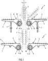
- FIG. 1 shows a schematic representation of an embodiment of an inventive system 1 when turning plate-shaped bodies 2, in particular slabs and sheets, different thickness.
- a plate-shaped body 2 is turned by means of the system 1, whose thickness is significantly smaller than the thickness of the plate-shaped body 2, which in the lower part of FIG. 1 is turned by the system 1.
- the system 1 comprises at least one turning arm 3, which is arranged pivotably about a pivot axis (not shown in greater detail), and at least one further turning arm 4 which is pivotable about a further pivot axis (not shown).
- the two pivot axes are arranged perpendicular to the plane of the drawing, parallel to each other and spaced apart from each other.
- a plurality of rollers 5 are arranged, whose roller axes are arranged perpendicular to the plane of the drawing.
- 3 or 4 lugs 6 are arranged for supporting the to-turn, plate-shaped body 2 at each Wenderarm.
- Each turning arm 3 or 4 is pivotable about a respective controllable actuator 7 about the respective pivot axis, which engages from below on the respective turning arm 3 or 4 and is pivotally connected to the respective turning arm 3 and 4, respectively.
- the system 1 comprises two drivable eccentric arrangements 8 and 9, with each of which a position of one of the pivot axes is adjustable before and / or during a turning operation.
- Each drivable eccentric 8 or 9 may have a fixedly arranged turning shaft 10 and at least one on at least one radial bearing on the turning shaft 10 arranged, driven eccentric bushing 11, wherein one of the Wenderarme 3 or 4 via at least one radial bearing not shown with the drivable Eccentric bushing 11 is connected.
- each drivable eccentric 3 and 4 a stationary and rotatably disposed about its longitudinal central axis disposed drivable turning shaft 10 and at least one arranged on the turning shaft 10, rotatably connected to the turning shaft 10 eccentric body 12, wherein one of the turning arms 3 and 4 via at least a radial bearing, not shown, is connected to the eccentric body 12.
- the drivable eccentric arrangements 8 or 9 according to the first-mentioned alternative and the respectively other drivable eccentric arrangement 9 or 8 according to the second-mentioned alternative.
- the system 1 may also comprise at least one measuring unit (not shown) for measuring the respective thickness of the plate-shaped body 2 to be turned and at least one system electronics not shown in communication with the measuring unit, the system electronics being arranged, the drivable eccentric arrangements 8 and 9 depending on to drive the respective measured thickness of the plate-shaped body to be used.
- each Wenderarm 3 or 4 is assigned its own controllable drive unit or a separate controllable actuator 7, which can be controlled independently are and about the control of the respective turning arm 3 and 4 is pivotable about the respective pivot axis.
- the turning arms 3 and 4 are pivoted in their horizontal positions shown by solid lines. Then can be placed on the Wenderarm 4 to be turned, plate-shaped body 2 and moved over the rollers 5 until it comes into physical contact with the arranged on the Wenderarm 4 noses 6, as in FIG. 1 shown on the right with dashed lines. Then, the Wenderarm 4 facing away flat side of the plate-shaped body 2 can be inspected. Subsequently, the thickness of the to be turned, plate-shaped body can be measured.
- the system electronics then drives the drivable eccentric assemblies 8 and 9 depending on the respective measured thickness of the plate-shaped body 2 to be used in order to drive the eccentric arrangements 8 and 9 in the in the upper part of FIG. 1 to bring shown positions.
- the Wenderarme 3 and 4 can be synchronized or pivoted independently of each other, as indicated by the center position of the Wenderarms 4 shown in dashed lines.
- the pivoting of the turning arms 3 and 4 takes place until the turning arms 3 and 4 have reached their vertical positions shown by dashed lines in the middle, in which the transfer of the plate-shaped body 2 from the turning arm 4 to the turning arm 3 takes place.
- the plate-shaped body 2 is supported, in particular, on the lugs 6 arranged on the turning arm 3.
- the Wenderarme 3 and 4 can be pivoted back into their horizontal positions, so that the turned, plate-shaped body rests on the Wenderarm 3 and the Wenderarm 3 facing away flat side of the plate-shaped body 2 can be inspected.
- FIG. 1 In the lower part of FIG. 1 is a feasible with the system 1 turning operation indicated in which a plate-shaped body 2 is turned, whose thickness is significantly greater than the thickness of the upper part of FIG. 1 shown, plate-shaped body 2 is.
- the Wenderwellen 11 and the eccentric bushes 12 have been driven to the driven eccentric assemblies 8 and 9 in the lower part of FIG. 1 to bring shown positions.
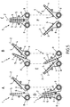
- FIG. 2 shows a schematic representation of another embodiment of a system according to the invention 1.
- the system 1 comprises six independently driven eccentric assemblies 8 and 9.
- the driven eccentric assemblies 8 and 9 each have a fixedly arranged turning shaft 10, on each of which four drivable eccentric bushings, not shown on in each case at least one not shown radial bearing are arranged.
- the Wenderwellen 10 are arranged in alignment with each other.
- the drivable Exzenteran angelen 8 and 9 each have a stationary and rotatable about its longitudinal central axis arranged, drivable turning shaft 10, on each of which four rotatably connected to the respective turning shaft 10, not shown eccentric body are arranged, each four Wenderarme 3 and 4, respectively are connected via at least one radial bearing, not shown, with the respective eccentric body, and wherein the Wenderwellen 10 are arranged in alignment with each other.
- a plate-shaped body 2 With the four drive eccentric arrangements 8 and 9 shown on the right, or their turning shafts 10 and eccentric bushings or eccentric bodies, as well as the turning arms 3 and 4 mounted on the turning shafts 10, a plate-shaped body 2 can be turned. At the same time, with the two drivable Exzenteran Aunten 8 and 9 or their Turning shafts 10 and eccentric bushings or eccentric bodies and the turning arms 3 and 4 mounted on the Wenderwellen 10 a plate-shaped body 2 are turned, the dimensions, in particular thickness, differ from the dimensions of the plate-shaped body 2 shown on the right.
- FIG. 3 shows a schematic representation of another embodiment of a system according to the invention 1. It can be seen a detail of the system 1, as it is for example in FIG. 2 is shown. In contrast to FIG. 2 are on a not shown, to be used, plate-shaped body 2 facing side of the connecting element 13, three mechanical damping element 14 is disposed of an elastomer.
- FIG. 4 shows a further schematic representation of the in FIG. 3 shown system 1 in the form of a side view, as shown in FIG. 1 is shown accordingly.
- a plate-shaped body 2 is placed on the Wenderarme 3.
- the mechanical damping elements 14 protrude from the connecting element 13 to the flat side of the plate-shaped body 2 facing the turning arm 3.
- the turning arms 3 can be connected via the connecting element 13 to a controllable actuator, not shown, via which the turning arms 3 are pivotable.
- FIG. 5 shows a schematic representation of a turning operation by means of in FIG. 1 shown system 1. To avoid repetition is to build the system 1 to the comments on FIG. 1 directed.
- the turning arm 3 To reach the position A, the turning arm 3 has been pivoted into its vertical position and the turning arm 4 together with the plate-shaped body 2 in the direction of its vertical position, wherein the eccentric assemblies 8 and 9 are in their neutral positions.
- the turning arm 3 To reach the position B, the turning arm 3 has been further pivoted in the direction of the turning arm 4 and at the same time the eccentric arrangements 8 and 9 are adjusted as shown.
- Position C the Wenderarme 3 and 4 were pivoted to their vertical positions and simultaneously the eccentric assemblies 8 and 9 as shown adjusted.
- the turning arms 3 and 4 were pivoted in the counterclockwise direction and at the same time the eccentric arrangements 8 and 9 were adjusted as shown.
- the turning arms 3 and 4 have been further pivoted counterclockwise while adjusting the eccentric assemblies 8 and 9 as shown.
- the turning arm 3 has been pivoted further counterclockwise and the turning arm 4 has been pivoted clockwise and at the same time the eccentric assemblies 8 and 9 have been moved to their neutral positions.
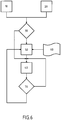
- FIG. 6 shows a representation of an embodiment of a method according to the invention for turning plate-shaped bodies, not shown, in particular slabs and sheets, using a turning system, not shown, at least one pivotable about a pivot axis arranged Wenderarm, with a flat side of a turning, plate-shaped body in physical contact can be brought, and at least one pivotable about a further pivot axis further turning arm which can be brought into physical contact with another flat side of the to be turned, plate-shaped body has.
- the two pivot axes are parallel to each other and spaced from each other.
- a position of at least one pivot axis is adjusted before and / or during a turning operation by means of at least one eccentric arrangement.
- the respective actual state of the turning system is detected.
- method step 20 parameters such as a thickness, length or the like of the respective plate-shaped body to be used are detected.
- method step 30 it is determined whether the position of the at least one eccentric arrangement is suitable for turning the plate-shaped body or not. If the position of the at least one eccentric arrangement is suitable for turning the plate-shaped body, the turning process is started in method step 40. Is the position of the at least one eccentric arrangement for turning the plate-shaped body is not suitable, the eccentric assembly is adjusted in step 50 in order to take an optimal position for turning the plate-shaped body.
- a data matrix 60 is used, in which relationships between parameters of plate-shaped bodies to be turned and positions of the eccentric arrangement are stored.
- step 70 it is monitored in method step 70 whether the eccentric arrangement is optimally set for the turning process or not. If the eccentric arrangement is set optimally for the turning process, the process goes to step 40. If the eccentric arrangement is not set optimally for the turning process, the process goes to step 50.
Landscapes
- Engineering & Computer Science (AREA)
- Mechanical Engineering (AREA)
- A Measuring Device Byusing Mechanical Method (AREA)
- Registering Or Overturning Sheets (AREA)
- Attitude Control For Articles On Conveyors (AREA)
- Soil Working Implements (AREA)
Applications Claiming Priority (2)
| Application Number | Priority Date | Filing Date | Title |
|---|---|---|---|
| DE102014224364.5A DE102014224364A1 (de) | 2014-11-28 | 2014-11-28 | System zum Wenden von plattenförmigen Körpern |
| PCT/EP2015/074790 WO2016083046A1 (de) | 2014-11-28 | 2015-10-27 | System zum wenden von plattenförmigen körpern |
Publications (2)
| Publication Number | Publication Date |
|---|---|
| EP3223973A1 EP3223973A1 (de) | 2017-10-04 |
| EP3223973B1 true EP3223973B1 (de) | 2018-07-25 |
Family
ID=54427723
Family Applications (1)
| Application Number | Title | Priority Date | Filing Date |
|---|---|---|---|
| EP15790492.1A Active EP3223973B1 (de) | 2014-11-28 | 2015-10-27 | System zum wenden von plattenförmigen körpern |
Country Status (7)
| Country | Link |
|---|---|
| US (1) | US10173847B2 (enExample) |
| EP (1) | EP3223973B1 (enExample) |
| JP (1) | JP6552617B2 (enExample) |
| KR (1) | KR102000571B1 (enExample) |
| CN (1) | CN107000005B (enExample) |
| DE (1) | DE102014224364A1 (enExample) |
| WO (1) | WO2016083046A1 (enExample) |
Cited By (1)
| Publication number | Priority date | Publication date | Assignee | Title |
|---|---|---|---|---|
| AT528097A2 (de) * | 2024-02-23 | 2025-09-15 | Sms Group Gmbh | Vorrichtung und Verfahren zum Wenden einer Metallbramme |
Families Citing this family (19)
| Publication number | Priority date | Publication date | Assignee | Title |
|---|---|---|---|---|
| CN107838311A (zh) * | 2017-11-29 | 2018-03-27 | 安徽戎发冲压机器人有限公司 | 长条钢板自动翻转装置 |
| CN108016845B (zh) * | 2017-11-30 | 2019-12-17 | 广西壮象木业有限公司 | 一种条形板材换向装置 |
| CN108147078A (zh) * | 2017-12-15 | 2018-06-12 | 柳州吉辉机械设计有限公司 | 一种自动翻锭装置 |
| CN108544252A (zh) * | 2018-04-04 | 2018-09-18 | 湖州旭源电气科技有限公司 | 一种用于汽车零部件加工翻转装置 |
| CN109502297A (zh) * | 2018-12-25 | 2019-03-22 | 苏州凡目视觉科技有限公司 | 工件全方位自动视觉检测装置 |
| CN112777281A (zh) * | 2019-11-05 | 2021-05-11 | 济南唐林智能科技有限公司 | 门窗自动翻转双面打胶生产线及其加工方法 |
| US11203492B2 (en) * | 2019-12-11 | 2021-12-21 | Symbotic Canada, Ulc | Case reorientation system and method |
| KR102203411B1 (ko) * | 2020-02-17 | 2021-01-21 | 하티스코리아(주) | 컴팩트 타입 가공물 반전 장치 및 이를 이용한 가공물 반전 방법 |
| AT523563B1 (de) * | 2020-03-03 | 2023-02-15 | Trumpf Maschinen Austria Gmbh & Co Kg | Vorrichtung und Verfahren zum Wenden von Blechen |
| CN111620082A (zh) * | 2020-05-18 | 2020-09-04 | 山东永安特种装备有限公司 | 一种气瓶免下架传输设备 |
| CN112192486A (zh) * | 2020-10-29 | 2021-01-08 | 天地宁夏支护装备有限公司 | 基于长方体重件的互插式半包型液压翻转机构 |
| CN112943719A (zh) * | 2021-01-25 | 2021-06-11 | 湖南三一快而居住宅工业有限公司 | 板材翻转机的液压控制系统及板材翻转机 |
| CN112978368B (zh) * | 2021-02-05 | 2022-04-22 | 浙江奇展机械制造有限公司 | 一种金属片取料翻转机构 |
| CN113734747B (zh) * | 2021-09-30 | 2023-03-31 | 惠州新联兴实业有限公司 | 一种线路板传输变向装置 |
| CN115092652A (zh) * | 2022-07-20 | 2022-09-23 | 常州贝高智能装备股份有限公司 | 板材翻面装置 |
| CN115256013B (zh) * | 2022-08-15 | 2024-04-09 | 普瓦尼尼智能装备(滁州)有限公司 | 一种防盗门门板成型线用翻面上料机构 |
| CN115402753A (zh) * | 2022-09-20 | 2022-11-29 | 山东煜卿钢结构有限公司 | 一种建筑装饰板材物料翻转整理装置 |
| CN115504208B (zh) * | 2022-09-29 | 2025-10-24 | 信维通信(江苏)有限公司 | 一种翻转机构及自动生产设备 |
| CN116267694B (zh) * | 2023-05-04 | 2024-04-02 | 华中农业大学 | 一种死猪捡拾车 |
Family Cites Families (33)
| Publication number | Priority date | Publication date | Assignee | Title |
|---|---|---|---|---|
| US1904434A (en) * | 1929-12-17 | 1933-04-18 | Mesta Machine Co | Cooling bed |
| US2235832A (en) * | 1940-01-30 | 1941-03-25 | Aluminum Co Of America | Work manipulator |
| US2499422A (en) * | 1948-02-20 | 1950-03-07 | American Can Co | Magnetic can turnover mechanism |
| US2863571A (en) * | 1953-10-02 | 1958-12-09 | Masonite Corp | Sheet handling apparatus |
| US3286854A (en) * | 1964-12-02 | 1966-11-22 | Richard B Crawford | Bale handling device |
| CA891279A (en) * | 1968-12-13 | 1972-01-25 | Dominion Engineering Works | Turnover apparatus |
| US3678781A (en) * | 1970-03-23 | 1972-07-25 | Roderick G Rohrberg | Adjustable throw eccentric |
| JPS5014227B1 (enExample) | 1970-09-16 | 1975-05-26 | ||
| US3741408A (en) * | 1971-08-02 | 1973-06-26 | Morgan Construction Co | Transfer apparatus |
| DE2165936A1 (de) * | 1971-12-31 | 1973-07-12 | Universale Ind Ofenbau Gmbh | Wendevorrichtung fuer brammen und dergleichen |
| US3977549A (en) * | 1975-02-10 | 1976-08-31 | Avant Industries, Inc. | Construction for clearing tableware from trays |
| JPS5349176Y2 (enExample) | 1975-03-19 | 1978-11-25 | ||
| SU861066A1 (ru) * | 1978-01-03 | 1981-09-07 | Московский Лесотехнический Институт | Устройство дл формировани пакета шпона |
| JPS6113125Y2 (enExample) * | 1980-09-30 | 1986-04-23 | ||
| DE3120585C2 (de) * | 1981-05-23 | 1985-01-24 | Bwg Bergwerk- Und Walzwerk-Maschinenbau Gmbh, 4100 Duisburg | Vorrichtung zum Wenden von Brammen oder dergleichen Halbzeug |
| DE3123673A1 (de) | 1981-06-15 | 1982-12-30 | Moeller & Neumann Gmbh, 6670 St Ingbert | Reversierbarer blechwender |
| JPS63278608A (ja) | 1987-05-11 | 1988-11-16 | Komai Tekkosho:Kk | 大板反転装置 |
| JPH0238111U (enExample) | 1988-09-07 | 1990-03-14 | ||
| JPH0337766Y2 (enExample) | 1990-09-28 | 1991-08-09 | ||
| IT1258041B (it) * | 1992-04-02 | 1996-02-20 | Dispositivo atto a raddrizzare contenitori da una posizione ad asse orizzontale ad una posizione ad asse verticale | |
| DE19728029C2 (de) * | 1997-07-01 | 2003-05-22 | Kammann Maschf Werner | Verfahren und Vorrichtung zum Dekorieren von flachen selbsttragenden Objekten |
| JP4207172B2 (ja) * | 1999-02-04 | 2009-01-14 | デンソン株式会社 | 重量物反転方法および装置 |
| JP2002046853A (ja) * | 2000-08-01 | 2002-02-12 | Mitsubishi Heavy Ind Ltd | スラブ反転装置 |
| JP2002205109A (ja) * | 2001-01-05 | 2002-07-23 | Kawasaki Steel Corp | H形鋼用転回装置 |
| JP2003276828A (ja) * | 2002-03-22 | 2003-10-02 | Noritake Co Ltd | 板状材反転装置 |
| JP4349783B2 (ja) * | 2002-09-20 | 2009-10-21 | 吉野石膏株式会社 | ボード反転装置及びボード反転方法 |
| CN2686802Y (zh) * | 2004-03-31 | 2005-03-23 | 河源龙记金属制品有限公司 | 一种翻板机构 |
| AT503937B1 (de) | 2006-12-27 | 2008-02-15 | Voest Alpine Ind Anlagen | Verfahren und vorrichtung zum wenden von plattenförmigen körpern |
| RU2436642C2 (ru) | 2007-07-20 | 2011-12-20 | Смс Зимаг Аг | Система контроля прокатываемых изделий и способ экспертизы поверхности прокатываемых изделий прокатного стана |
| US7631479B2 (en) * | 2007-10-23 | 2009-12-15 | Deere & Company | Adjustable pivot axis for bedknife assembly |
| US9375773B2 (en) * | 2010-05-05 | 2016-06-28 | Textron Innovations Inc. | Circuit for conduit bender |
| CN201921894U (zh) * | 2010-12-30 | 2011-08-10 | 一重集团大连设计研究院有限公司 | 可变转臂间距的翻板机 |
| CN103909947B (zh) * | 2014-03-14 | 2016-05-04 | 南车南京浦镇车辆有限公司 | 轮对提吊间隙调整方法 |
-
2014
- 2014-11-28 DE DE102014224364.5A patent/DE102014224364A1/de not_active Withdrawn
-
2015
- 2015-10-27 EP EP15790492.1A patent/EP3223973B1/de active Active
- 2015-10-27 JP JP2017528462A patent/JP6552617B2/ja active Active
- 2015-10-27 KR KR1020177014733A patent/KR102000571B1/ko active Active
- 2015-10-27 US US15/531,246 patent/US10173847B2/en active Active
- 2015-10-27 WO PCT/EP2015/074790 patent/WO2016083046A1/de not_active Ceased
- 2015-10-27 CN CN201580064892.4A patent/CN107000005B/zh active Active
Non-Patent Citations (1)
| Title |
|---|
| None * |
Cited By (1)
| Publication number | Priority date | Publication date | Assignee | Title |
|---|---|---|---|---|
| AT528097A2 (de) * | 2024-02-23 | 2025-09-15 | Sms Group Gmbh | Vorrichtung und Verfahren zum Wenden einer Metallbramme |
Also Published As
| Publication number | Publication date |
|---|---|
| EP3223973A1 (de) | 2017-10-04 |
| CN107000005A (zh) | 2017-08-01 |
| DE102014224364A8 (de) | 2016-10-20 |
| KR102000571B1 (ko) | 2019-07-16 |
| JP2018505107A (ja) | 2018-02-22 |
| DE102014224364A1 (de) | 2016-06-02 |
| US10173847B2 (en) | 2019-01-08 |
| CN107000005B (zh) | 2020-04-03 |
| KR20170076770A (ko) | 2017-07-04 |
| WO2016083046A1 (de) | 2016-06-02 |
| US20170326606A1 (en) | 2017-11-16 |
| JP6552617B2 (ja) | 2019-07-31 |
Similar Documents
| Publication | Publication Date | Title |
|---|---|---|
| EP3223973B1 (de) | System zum wenden von plattenförmigen körpern | |
| EP2170536B1 (de) | Inspektionssystem für walzprodukte und verfahren zur begutachtung der oberfläche von walzprodukten einer walzanlage | |
| EP2825332B1 (de) | Vorrichtung und verfahren zum richten von metallband | |
| EP2467233B1 (de) | Vorrichtung zum handhaben von brammen zum schleifen der brammen-oberflächen | |
| EP2708324B1 (de) | Tischplatte für Federauflagetisch einer Federendenschleifmaschine sowie Federendenschleifmaschine damit | |
| EP3218204B1 (de) | Beschichtungsanlage mit walzen | |
| DE202014102800U1 (de) | Segmentierte Bauteilauflage | |
| WO2014053120A1 (de) | Verfahren zum steuern einer keramik- oder metallpulver-presse bzw. keramik- oder metallpulver-presse | |
| DE69909977T2 (de) | Vorrichtung zum Stumpf-Laserschweissen von Blechen (vorbestimmten Zuschnitten), die magnetische Rollen hat um die Bleche nach der Schweissposition zu bewegen und die aktive Klemmen hat, um die Bleche zu klemmen | |
| WO2010040157A1 (de) | Portalkran | |
| EP3325186B1 (de) | Anlage und verfahren zum beseitigen von planheitsfehlern eines metallischen flachprodukts | |
| EP1949982A2 (de) | Walzvorrichtung und Verfahren zum Einrollen von Verbindungsstegen in Profile | |
| WO2019057577A1 (de) | Ofenrolle, transportvorrichtung hiermit und verfahren zu deren betrieb | |
| EP3140631B1 (de) | Vorrichtung zur drehbaren lagerung von werkstücken, insbesondere kurbelwellen | |
| EP0957057A2 (de) | Längsfalzeinrichtung am Falzapparat von Rotationsdruckmaschinen | |
| WO2017032652A1 (de) | Richtmaschine mit modular aufgebautem wechselkassettensystem | |
| EP3558557B1 (de) | Vorrichtung und verfahren zum formen eines bleches | |
| AT518997B1 (de) | Vorrichtung zum Bearbeiten und Transportieren von Teigbändern | |
| EP4313437B1 (de) | Verfahren und vorrcihtung zum führen und zentrieren eines metallenen walzguts in einer walzstrasse | |
| DE1028960B (de) | Vorrichtung zum Kanten von Walzgut | |
| DE602004002985T2 (de) | Vorrichtung zum Krimpen von Metallblechen | |
| DE102023135697A1 (de) | Vorrichtung zur Ausrichtung eines Bogens in einem Anleger einer bogenverarbeitenden Maschine | |
| DE1602156B2 (de) | Vorrichtung zum transportieren von langgestrecktem walzgut quer zu seiner laengsachse | |
| DE102024133793A1 (de) | Vorrichtung zur Ausrichtung eines Bogens in einem Anleger einer bogenverarbeitenden Maschine | |
| DE2017440B2 (de) | Fräsmaschine zum Bearbeiten von Profilflächen |
Legal Events
| Date | Code | Title | Description |
|---|---|---|---|
| PUAI | Public reference made under article 153(3) epc to a published international application that has entered the european phase |
Free format text: ORIGINAL CODE: 0009012 |
|
| 17P | Request for examination filed |
Effective date: 20170628 |
|
| AK | Designated contracting states |
Kind code of ref document: A1 Designated state(s): AL AT BE BG CH CY CZ DE DK EE ES FI FR GB GR HR HU IE IS IT LI LT LU LV MC MK MT NL NO PL PT RO RS SE SI SK SM TR |
|
| AX | Request for extension of the european patent |
Extension state: BA ME |
|
| GRAP | Despatch of communication of intention to grant a patent |
Free format text: ORIGINAL CODE: EPIDOSNIGR1 |
|
| DAV | Request for validation of the european patent (deleted) | ||
| DAX | Request for extension of the european patent (deleted) | ||
| INTG | Intention to grant announced |
Effective date: 20180222 |
|
| GRAS | Grant fee paid |
Free format text: ORIGINAL CODE: EPIDOSNIGR3 |
|
| GRAA | (expected) grant |
Free format text: ORIGINAL CODE: 0009210 |
|
| AK | Designated contracting states |
Kind code of ref document: B1 Designated state(s): AL AT BE BG CH CY CZ DE DK EE ES FI FR GB GR HR HU IE IS IT LI LT LU LV MC MK MT NL NO PL PT RO RS SE SI SK SM TR |
|
| REG | Reference to a national code |
Ref country code: GB Ref legal event code: FG4D Free format text: NOT ENGLISH |
|
| REG | Reference to a national code |
Ref country code: CH Ref legal event code: EP |
|
| REG | Reference to a national code |
Ref country code: AT Ref legal event code: REF Ref document number: 1021205 Country of ref document: AT Kind code of ref document: T Effective date: 20180815 |
|
| REG | Reference to a national code |
Ref country code: IE Ref legal event code: FG4D Free format text: LANGUAGE OF EP DOCUMENT: GERMAN |
|
| REG | Reference to a national code |
Ref country code: DE Ref legal event code: R096 Ref document number: 502015005251 Country of ref document: DE |
|
| REG | Reference to a national code |
Ref country code: NL Ref legal event code: MP Effective date: 20180725 |
|
| REG | Reference to a national code |
Ref country code: LT Ref legal event code: MG4D |
|
| PG25 | Lapsed in a contracting state [announced via postgrant information from national office to epo] |
Ref country code: NL Free format text: LAPSE BECAUSE OF FAILURE TO SUBMIT A TRANSLATION OF THE DESCRIPTION OR TO PAY THE FEE WITHIN THE PRESCRIBED TIME-LIMIT Effective date: 20180725 |
|
| PG25 | Lapsed in a contracting state [announced via postgrant information from national office to epo] |
Ref country code: BG Free format text: LAPSE BECAUSE OF FAILURE TO SUBMIT A TRANSLATION OF THE DESCRIPTION OR TO PAY THE FEE WITHIN THE PRESCRIBED TIME-LIMIT Effective date: 20181025 Ref country code: SE Free format text: LAPSE BECAUSE OF FAILURE TO SUBMIT A TRANSLATION OF THE DESCRIPTION OR TO PAY THE FEE WITHIN THE PRESCRIBED TIME-LIMIT Effective date: 20180725 Ref country code: RS Free format text: LAPSE BECAUSE OF FAILURE TO SUBMIT A TRANSLATION OF THE DESCRIPTION OR TO PAY THE FEE WITHIN THE PRESCRIBED TIME-LIMIT Effective date: 20180725 Ref country code: IS Free format text: LAPSE BECAUSE OF FAILURE TO SUBMIT A TRANSLATION OF THE DESCRIPTION OR TO PAY THE FEE WITHIN THE PRESCRIBED TIME-LIMIT Effective date: 20181125 Ref country code: GR Free format text: LAPSE BECAUSE OF FAILURE TO SUBMIT A TRANSLATION OF THE DESCRIPTION OR TO PAY THE FEE WITHIN THE PRESCRIBED TIME-LIMIT Effective date: 20181026 Ref country code: NO Free format text: LAPSE BECAUSE OF FAILURE TO SUBMIT A TRANSLATION OF THE DESCRIPTION OR TO PAY THE FEE WITHIN THE PRESCRIBED TIME-LIMIT Effective date: 20181025 Ref country code: PL Free format text: LAPSE BECAUSE OF FAILURE TO SUBMIT A TRANSLATION OF THE DESCRIPTION OR TO PAY THE FEE WITHIN THE PRESCRIBED TIME-LIMIT Effective date: 20180725 Ref country code: LT Free format text: LAPSE BECAUSE OF FAILURE TO SUBMIT A TRANSLATION OF THE DESCRIPTION OR TO PAY THE FEE WITHIN THE PRESCRIBED TIME-LIMIT Effective date: 20180725 Ref country code: FI Free format text: LAPSE BECAUSE OF FAILURE TO SUBMIT A TRANSLATION OF THE DESCRIPTION OR TO PAY THE FEE WITHIN THE PRESCRIBED TIME-LIMIT Effective date: 20180725 |
|
| PG25 | Lapsed in a contracting state [announced via postgrant information from national office to epo] |
Ref country code: LV Free format text: LAPSE BECAUSE OF FAILURE TO SUBMIT A TRANSLATION OF THE DESCRIPTION OR TO PAY THE FEE WITHIN THE PRESCRIBED TIME-LIMIT Effective date: 20180725 Ref country code: AL Free format text: LAPSE BECAUSE OF FAILURE TO SUBMIT A TRANSLATION OF THE DESCRIPTION OR TO PAY THE FEE WITHIN THE PRESCRIBED TIME-LIMIT Effective date: 20180725 Ref country code: HR Free format text: LAPSE BECAUSE OF FAILURE TO SUBMIT A TRANSLATION OF THE DESCRIPTION OR TO PAY THE FEE WITHIN THE PRESCRIBED TIME-LIMIT Effective date: 20180725 |
|
| REG | Reference to a national code |
Ref country code: DE Ref legal event code: R097 Ref document number: 502015005251 Country of ref document: DE |
|
| PG25 | Lapsed in a contracting state [announced via postgrant information from national office to epo] |
Ref country code: EE Free format text: LAPSE BECAUSE OF FAILURE TO SUBMIT A TRANSLATION OF THE DESCRIPTION OR TO PAY THE FEE WITHIN THE PRESCRIBED TIME-LIMIT Effective date: 20180725 Ref country code: ES Free format text: LAPSE BECAUSE OF FAILURE TO SUBMIT A TRANSLATION OF THE DESCRIPTION OR TO PAY THE FEE WITHIN THE PRESCRIBED TIME-LIMIT Effective date: 20180725 Ref country code: RO Free format text: LAPSE BECAUSE OF FAILURE TO SUBMIT A TRANSLATION OF THE DESCRIPTION OR TO PAY THE FEE WITHIN THE PRESCRIBED TIME-LIMIT Effective date: 20180725 Ref country code: CZ Free format text: LAPSE BECAUSE OF FAILURE TO SUBMIT A TRANSLATION OF THE DESCRIPTION OR TO PAY THE FEE WITHIN THE PRESCRIBED TIME-LIMIT Effective date: 20180725 |
|
| PG25 | Lapsed in a contracting state [announced via postgrant information from national office to epo] |
Ref country code: DK Free format text: LAPSE BECAUSE OF FAILURE TO SUBMIT A TRANSLATION OF THE DESCRIPTION OR TO PAY THE FEE WITHIN THE PRESCRIBED TIME-LIMIT Effective date: 20180725 Ref country code: SM Free format text: LAPSE BECAUSE OF FAILURE TO SUBMIT A TRANSLATION OF THE DESCRIPTION OR TO PAY THE FEE WITHIN THE PRESCRIBED TIME-LIMIT Effective date: 20180725 Ref country code: SK Free format text: LAPSE BECAUSE OF FAILURE TO SUBMIT A TRANSLATION OF THE DESCRIPTION OR TO PAY THE FEE WITHIN THE PRESCRIBED TIME-LIMIT Effective date: 20180725 |
|
| PLBE | No opposition filed within time limit |
Free format text: ORIGINAL CODE: 0009261 |
|
| REG | Reference to a national code |
Ref country code: CH Ref legal event code: PL |
|
| STAA | Information on the status of an ep patent application or granted ep patent |
Free format text: STATUS: NO OPPOSITION FILED WITHIN TIME LIMIT |
|
| REG | Reference to a national code |
Ref country code: BE Ref legal event code: MM Effective date: 20181031 |
|
| PG25 | Lapsed in a contracting state [announced via postgrant information from national office to epo] |
Ref country code: LU Free format text: LAPSE BECAUSE OF NON-PAYMENT OF DUE FEES Effective date: 20181027 Ref country code: MC Free format text: LAPSE BECAUSE OF FAILURE TO SUBMIT A TRANSLATION OF THE DESCRIPTION OR TO PAY THE FEE WITHIN THE PRESCRIBED TIME-LIMIT Effective date: 20180725 |
|
| 26N | No opposition filed |
Effective date: 20190426 |
|
| REG | Reference to a national code |
Ref country code: IE Ref legal event code: MM4A |
|
| PG25 | Lapsed in a contracting state [announced via postgrant information from national office to epo] |
Ref country code: LI Free format text: LAPSE BECAUSE OF NON-PAYMENT OF DUE FEES Effective date: 20181031 Ref country code: CH Free format text: LAPSE BECAUSE OF NON-PAYMENT OF DUE FEES Effective date: 20181031 Ref country code: FR Free format text: LAPSE BECAUSE OF NON-PAYMENT OF DUE FEES Effective date: 20181031 Ref country code: SI Free format text: LAPSE BECAUSE OF FAILURE TO SUBMIT A TRANSLATION OF THE DESCRIPTION OR TO PAY THE FEE WITHIN THE PRESCRIBED TIME-LIMIT Effective date: 20180725 Ref country code: BE Free format text: LAPSE BECAUSE OF NON-PAYMENT OF DUE FEES Effective date: 20181031 |
|
| PG25 | Lapsed in a contracting state [announced via postgrant information from national office to epo] |
Ref country code: IE Free format text: LAPSE BECAUSE OF NON-PAYMENT OF DUE FEES Effective date: 20181027 |
|
| PG25 | Lapsed in a contracting state [announced via postgrant information from national office to epo] |
Ref country code: MT Free format text: LAPSE BECAUSE OF FAILURE TO SUBMIT A TRANSLATION OF THE DESCRIPTION OR TO PAY THE FEE WITHIN THE PRESCRIBED TIME-LIMIT Effective date: 20180725 |
|
| PG25 | Lapsed in a contracting state [announced via postgrant information from national office to epo] |
Ref country code: TR Free format text: LAPSE BECAUSE OF FAILURE TO SUBMIT A TRANSLATION OF THE DESCRIPTION OR TO PAY THE FEE WITHIN THE PRESCRIBED TIME-LIMIT Effective date: 20180725 |
|
| PG25 | Lapsed in a contracting state [announced via postgrant information from national office to epo] |
Ref country code: PT Free format text: LAPSE BECAUSE OF FAILURE TO SUBMIT A TRANSLATION OF THE DESCRIPTION OR TO PAY THE FEE WITHIN THE PRESCRIBED TIME-LIMIT Effective date: 20180725 |
|
| PG25 | Lapsed in a contracting state [announced via postgrant information from national office to epo] |
Ref country code: HU Free format text: LAPSE BECAUSE OF FAILURE TO SUBMIT A TRANSLATION OF THE DESCRIPTION OR TO PAY THE FEE WITHIN THE PRESCRIBED TIME-LIMIT; INVALID AB INITIO Effective date: 20151027 Ref country code: CY Free format text: LAPSE BECAUSE OF FAILURE TO SUBMIT A TRANSLATION OF THE DESCRIPTION OR TO PAY THE FEE WITHIN THE PRESCRIBED TIME-LIMIT Effective date: 20180725 Ref country code: MK Free format text: LAPSE BECAUSE OF NON-PAYMENT OF DUE FEES Effective date: 20180725 |
|
| P01 | Opt-out of the competence of the unified patent court (upc) registered |
Effective date: 20230707 |
|
| PGFP | Annual fee paid to national office [announced via postgrant information from national office to epo] |
Ref country code: DE Payment date: 20241021 Year of fee payment: 10 |
|
| PGFP | Annual fee paid to national office [announced via postgrant information from national office to epo] |
Ref country code: GB Payment date: 20241025 Year of fee payment: 10 |
|
| PGFP | Annual fee paid to national office [announced via postgrant information from national office to epo] |
Ref country code: AT Payment date: 20241022 Year of fee payment: 10 |
|
| PGFP | Annual fee paid to national office [announced via postgrant information from national office to epo] |
Ref country code: IT Payment date: 20241025 Year of fee payment: 10 |