EP3221648B1 - Klimaanlage mit einem flüssigen trocknungsmittel - Google Patents
Klimaanlage mit einem flüssigen trocknungsmittel Download PDFInfo
- Publication number
- EP3221648B1 EP3221648B1 EP15861611.0A EP15861611A EP3221648B1 EP 3221648 B1 EP3221648 B1 EP 3221648B1 EP 15861611 A EP15861611 A EP 15861611A EP 3221648 B1 EP3221648 B1 EP 3221648B1
- Authority
- EP
- European Patent Office
- Prior art keywords
- transfer fluid
- heat transfer
- air
- liquid desiccant
- refrigerant
- Prior art date
- Legal status (The legal status is an assumption and is not a legal conclusion. Google has not performed a legal analysis and makes no representation as to the accuracy of the status listed.)
- Active
Links
Images


Classifications
-
- F—MECHANICAL ENGINEERING; LIGHTING; HEATING; WEAPONS; BLASTING
- F24—HEATING; RANGES; VENTILATING
- F24F—AIR-CONDITIONING; AIR-HUMIDIFICATION; VENTILATION; USE OF AIR CURRENTS FOR SCREENING
- F24F3/00—Air-conditioning systems in which conditioned primary air is supplied from one or more central stations to distributing units in the rooms or spaces where it may receive secondary treatment; Apparatus specially designed for such systems
- F24F3/12—Air-conditioning systems in which conditioned primary air is supplied from one or more central stations to distributing units in the rooms or spaces where it may receive secondary treatment; Apparatus specially designed for such systems characterised by the treatment of the air otherwise than by heating and cooling
- F24F3/14—Air-conditioning systems in which conditioned primary air is supplied from one or more central stations to distributing units in the rooms or spaces where it may receive secondary treatment; Apparatus specially designed for such systems characterised by the treatment of the air otherwise than by heating and cooling by humidification; by dehumidification
- F24F3/1411—Air-conditioning systems in which conditioned primary air is supplied from one or more central stations to distributing units in the rooms or spaces where it may receive secondary treatment; Apparatus specially designed for such systems characterised by the treatment of the air otherwise than by heating and cooling by humidification; by dehumidification by absorbing or adsorbing water, e.g. using an hygroscopic desiccant
- F24F3/1417—Air-conditioning systems in which conditioned primary air is supplied from one or more central stations to distributing units in the rooms or spaces where it may receive secondary treatment; Apparatus specially designed for such systems characterised by the treatment of the air otherwise than by heating and cooling by humidification; by dehumidification by absorbing or adsorbing water, e.g. using an hygroscopic desiccant with liquid hygroscopic desiccants
-
- F—MECHANICAL ENGINEERING; LIGHTING; HEATING; WEAPONS; BLASTING
- F24—HEATING; RANGES; VENTILATING
- F24F—AIR-CONDITIONING; AIR-HUMIDIFICATION; VENTILATION; USE OF AIR CURRENTS FOR SCREENING
- F24F3/00—Air-conditioning systems in which conditioned primary air is supplied from one or more central stations to distributing units in the rooms or spaces where it may receive secondary treatment; Apparatus specially designed for such systems
- F24F3/12—Air-conditioning systems in which conditioned primary air is supplied from one or more central stations to distributing units in the rooms or spaces where it may receive secondary treatment; Apparatus specially designed for such systems characterised by the treatment of the air otherwise than by heating and cooling
- F24F3/14—Air-conditioning systems in which conditioned primary air is supplied from one or more central stations to distributing units in the rooms or spaces where it may receive secondary treatment; Apparatus specially designed for such systems characterised by the treatment of the air otherwise than by heating and cooling by humidification; by dehumidification
-
- F—MECHANICAL ENGINEERING; LIGHTING; HEATING; WEAPONS; BLASTING
- F24—HEATING; RANGES; VENTILATING
- F24F—AIR-CONDITIONING; AIR-HUMIDIFICATION; VENTILATION; USE OF AIR CURRENTS FOR SCREENING
- F24F1/00—Room units for air-conditioning, e.g. separate or self-contained units or units receiving primary air from a central station
- F24F1/0003—Room units for air-conditioning, e.g. separate or self-contained units or units receiving primary air from a central station characterised by a split arrangement, wherein parts of the air-conditioning system, e.g. evaporator and condenser, are in separately located units
-
- F—MECHANICAL ENGINEERING; LIGHTING; HEATING; WEAPONS; BLASTING
- F25—REFRIGERATION OR COOLING; COMBINED HEATING AND REFRIGERATION SYSTEMS; HEAT PUMP SYSTEMS; MANUFACTURE OR STORAGE OF ICE; LIQUEFACTION SOLIDIFICATION OF GASES
- F25B—REFRIGERATION MACHINES, PLANTS OR SYSTEMS; COMBINED HEATING AND REFRIGERATION SYSTEMS; HEAT PUMP SYSTEMS
- F25B13/00—Compression machines, plants or systems, with reversible cycle
-
- F—MECHANICAL ENGINEERING; LIGHTING; HEATING; WEAPONS; BLASTING
- F25—REFRIGERATION OR COOLING; COMBINED HEATING AND REFRIGERATION SYSTEMS; HEAT PUMP SYSTEMS; MANUFACTURE OR STORAGE OF ICE; LIQUEFACTION SOLIDIFICATION OF GASES
- F25B—REFRIGERATION MACHINES, PLANTS OR SYSTEMS; COMBINED HEATING AND REFRIGERATION SYSTEMS; HEAT PUMP SYSTEMS
- F25B25/00—Machines, plants or systems, using a combination of modes of operation covered by two or more of the groups F25B1/00 - F25B23/00
- F25B25/005—Machines, plants or systems, using a combination of modes of operation covered by two or more of the groups F25B1/00 - F25B23/00 using primary and secondary systems
-
- F—MECHANICAL ENGINEERING; LIGHTING; HEATING; WEAPONS; BLASTING
- F25—REFRIGERATION OR COOLING; COMBINED HEATING AND REFRIGERATION SYSTEMS; HEAT PUMP SYSTEMS; MANUFACTURE OR STORAGE OF ICE; LIQUEFACTION SOLIDIFICATION OF GASES
- F25B—REFRIGERATION MACHINES, PLANTS OR SYSTEMS; COMBINED HEATING AND REFRIGERATION SYSTEMS; HEAT PUMP SYSTEMS
- F25B41/00—Fluid-circulation arrangements
- F25B41/20—Disposition of valves, e.g. of on-off valves or flow control valves
-
- F—MECHANICAL ENGINEERING; LIGHTING; HEATING; WEAPONS; BLASTING
- F25—REFRIGERATION OR COOLING; COMBINED HEATING AND REFRIGERATION SYSTEMS; HEAT PUMP SYSTEMS; MANUFACTURE OR STORAGE OF ICE; LIQUEFACTION SOLIDIFICATION OF GASES
- F25B—REFRIGERATION MACHINES, PLANTS OR SYSTEMS; COMBINED HEATING AND REFRIGERATION SYSTEMS; HEAT PUMP SYSTEMS
- F25B49/00—Arrangement or mounting of control or safety devices
- F25B49/02—Arrangement or mounting of control or safety devices for compression type machines, plants or systems
-
- F—MECHANICAL ENGINEERING; LIGHTING; HEATING; WEAPONS; BLASTING
- F24—HEATING; RANGES; VENTILATING
- F24F—AIR-CONDITIONING; AIR-HUMIDIFICATION; VENTILATION; USE OF AIR CURRENTS FOR SCREENING
- F24F3/00—Air-conditioning systems in which conditioned primary air is supplied from one or more central stations to distributing units in the rooms or spaces where it may receive secondary treatment; Apparatus specially designed for such systems
- F24F3/12—Air-conditioning systems in which conditioned primary air is supplied from one or more central stations to distributing units in the rooms or spaces where it may receive secondary treatment; Apparatus specially designed for such systems characterised by the treatment of the air otherwise than by heating and cooling
- F24F3/14—Air-conditioning systems in which conditioned primary air is supplied from one or more central stations to distributing units in the rooms or spaces where it may receive secondary treatment; Apparatus specially designed for such systems characterised by the treatment of the air otherwise than by heating and cooling by humidification; by dehumidification
- F24F2003/1435—Air-conditioning systems in which conditioned primary air is supplied from one or more central stations to distributing units in the rooms or spaces where it may receive secondary treatment; Apparatus specially designed for such systems characterised by the treatment of the air otherwise than by heating and cooling by humidification; by dehumidification comprising semi-permeable membrane
-
- F—MECHANICAL ENGINEERING; LIGHTING; HEATING; WEAPONS; BLASTING
- F24—HEATING; RANGES; VENTILATING
- F24F—AIR-CONDITIONING; AIR-HUMIDIFICATION; VENTILATION; USE OF AIR CURRENTS FOR SCREENING
- F24F3/00—Air-conditioning systems in which conditioned primary air is supplied from one or more central stations to distributing units in the rooms or spaces where it may receive secondary treatment; Apparatus specially designed for such systems
- F24F3/12—Air-conditioning systems in which conditioned primary air is supplied from one or more central stations to distributing units in the rooms or spaces where it may receive secondary treatment; Apparatus specially designed for such systems characterised by the treatment of the air otherwise than by heating and cooling
- F24F3/14—Air-conditioning systems in which conditioned primary air is supplied from one or more central stations to distributing units in the rooms or spaces where it may receive secondary treatment; Apparatus specially designed for such systems characterised by the treatment of the air otherwise than by heating and cooling by humidification; by dehumidification
- F24F2003/1458—Air-conditioning systems in which conditioned primary air is supplied from one or more central stations to distributing units in the rooms or spaces where it may receive secondary treatment; Apparatus specially designed for such systems characterised by the treatment of the air otherwise than by heating and cooling by humidification; by dehumidification using regenerators
-
- F—MECHANICAL ENGINEERING; LIGHTING; HEATING; WEAPONS; BLASTING
- F25—REFRIGERATION OR COOLING; COMBINED HEATING AND REFRIGERATION SYSTEMS; HEAT PUMP SYSTEMS; MANUFACTURE OR STORAGE OF ICE; LIQUEFACTION SOLIDIFICATION OF GASES
- F25B—REFRIGERATION MACHINES, PLANTS OR SYSTEMS; COMBINED HEATING AND REFRIGERATION SYSTEMS; HEAT PUMP SYSTEMS
- F25B2313/00—Compression machines, plants or systems with reversible cycle not otherwise provided for
- F25B2313/027—Compression machines, plants or systems with reversible cycle not otherwise provided for characterised by the reversing means
- F25B2313/02732—Compression machines, plants or systems with reversible cycle not otherwise provided for characterised by the reversing means using two three-way valves
-
- F—MECHANICAL ENGINEERING; LIGHTING; HEATING; WEAPONS; BLASTING
- F25—REFRIGERATION OR COOLING; COMBINED HEATING AND REFRIGERATION SYSTEMS; HEAT PUMP SYSTEMS; MANUFACTURE OR STORAGE OF ICE; LIQUEFACTION SOLIDIFICATION OF GASES
- F25B—REFRIGERATION MACHINES, PLANTS OR SYSTEMS; COMBINED HEATING AND REFRIGERATION SYSTEMS; HEAT PUMP SYSTEMS
- F25B2313/00—Compression machines, plants or systems with reversible cycle not otherwise provided for
- F25B2313/027—Compression machines, plants or systems with reversible cycle not otherwise provided for characterised by the reversing means
- F25B2313/02741—Compression machines, plants or systems with reversible cycle not otherwise provided for characterised by the reversing means using one four-way valve
Definitions
- the present application relates generally to the use of liquid desiccants to dehumidify and cool, or heat and humidify an air stream entering a space. More specifically, the application relates to the replacement of conventional mini-split air conditioning units with (membrane based) liquid desiccant air conditioning system to accomplish the same heating and cooling capabilities as those conventional mini-split air conditioners and at the same time to provide additional functionality such as, for example, the ability for the system to heat and simultaneously humidify the space or for the system to heat and simultaneously dehumidify a space thereby providing for healthier indoor air conditions than conventional systems will provide.
- Desiccant dehumidification systems -both liquid and solid desiccants - have been used parallel to conventional vapor compression HVAC equipment to help reduce humidity in spaces, particularly in spaces that require large amounts of outdoor air or that have large humidity loads inside the building space itself.
- Humid climates, such as for example Miami, FL require a lot of energy to properly treat (dehumidify and cool) the fresh air that is required for a space's occupant comfort.
- Desiccant dehumidification systems - both solid and liquid - have been used for many years and are generally quite efficient at removing moisture from the air stream.
- liquid desiccant systems generally use concentrated salt solutions such as ionic solutions of LiCl, LiBr or CaCl 2 and water.
- concentrated salt solutions such as ionic solutions of LiCl, LiBr or CaCl 2 and water.
- Such brines are strongly corrosive to metals, even in small quantities, so numerous attempts have been made over the years to prevent desiccant carry-over to the air stream that is to be treated.
- efforts have begun to eliminate the risk of desiccant carry-over by employing micro-porous membranes to contain the desiccant solution.
- membrane based liquid desiccant systems have been primarily applied to unitary rooftop units for commercial buildings.
- mini-split air conditioners wherein the condenser (together with the compressor and control system) is located outside and the evaporator cooling coil is installed in the room or space than needs to be cooled, and unitary rooftop units are not an appropriate choice for servicing those spaces.
- the mini-split air conditioning system is the preferred method of cooling (and sometimes heating) a space.
- Liquid desiccant systems generally have two separate functions.
- the conditioning side of the system provides conditioning of air to the required conditions, which are typically set using thermostats or humidistats.
- the regeneration side of the system provides a reconditioning function of the liquid desiccant so that it can be re-used on the conditioning side.
- Liquid desiccant is typically pumped or moved between the two sides, and a control system helps to ensure that the liquid desiccant is properly balanced between the two sides as conditions necessitate and that excess heat and moisture are properly dealt with without leading to over-concentrating or under-concentrating of the desiccant.
- Mini-split systems typically take in 100% of room air through the evaporator coil and fresh air only reaches the room through ventilation and infiltration from other sources. This often can result in high humidity and cool temperatures in the space since the evaporator coil is not very efficient for removing moisture. Rather, the evaporator coil is better suited for sensible cooling. On days where only a small amount of cooling is required, the building can reach unacceptable levels of humidity since not enough natural heat is available to balance the large amount of sensible cooling. Equally on colder humid days, such as in the rainy season, heating the air would be preferred while also dehumidifying it. Mini-split systems are typically unable to provide dehumidification, although they will provide heating if they are setup as a heat pump.
- a condenser with compressor is installed outside and high pressure refrigerant lines connect the two components. Furthermore a drain line for condensate is installed on the indoor coil unit to remove moisture that is condensed on the evaporator coil to the outside.
- a liquid desiccant system can significantly reduce electricity consumption and can be easier to install without the need for high pressure refrigerant lines. The advantage of such an approach is that a significant portion of the cost of a mini-split system is the actual installation (the running, filling and testing of refrigerant line) that need to be installed on site.
- the refrigerant lines run into the space, the refrigerant selections are limited to non-flammable and non-toxic substances. By keeping all of the refrigerant components outside, the number of available refrigerants can be expanded to include ones that otherwise would not be allowed, such as propane etc.
- US 2014/260399 A1 (Vandermeulen Peter F ) describes a split liquid desiccant air conditioning system for treating an air stream flowing into a space in a building.
- the system is switchable between operating in a warm weather operation mode and a cold weather operation mode.
- a liquid desiccant air-conditioning system operable in a cooling and dehumidification mode, a heating and humidification mode, and/or a heating and dehumidification mode.
- the system comprises a conditioner for treating a first air stream flowing therethrough and provided to a space, said conditioner using a heat transfer fluid and a liquid desiccant to cool and dehumidify the first air stream in the cooling and dehumidification mode, heat and humidify the first air stream in the heating and humidification mode, and heat and dehumidify the first air stream in the heating and dehumidification mode.
- regenerator connected to the conditioner such that the liquid desiccant can be circulated between the regenerator and the conditioner, the regenerator causing the liquid desiccant to desorb water vapor to a second air stream in the cooling and dehumidification mode and in the heating and dehumidification mode, and causing the liquid desiccant to absorb water vapor from the second air stream in the heating and humidification mode.
- This aspect also includes a refrigerant system including a compressor and at least one expansion valve processing a refrigerant.
- first refrigerant-to-heat transfer fluid heat exchanger connected to the conditioner and the refrigerant system for exchanging heat between the refrigerant heated or cooled by the refrigerant system and the heat transfer fluid used in the conditioner and a second refrigerant-to-heat transfer fluid heat connected to the regenerator and the refrigerant system for exchanging heat between the refrigerant heated or cooled by the refrigerant system and the heat transfer fluid used in the regenerator.
- This aspect utilizes a heat transfer fluid-to-air heat exchanger for exchanging heat between the heat transfer fluid used in the regenerator and a third air stream when the air-conditioning system is operating in the cooling and dehumidification mode or the heating and humidification mode, said heat transfer fluid-to-air heat exchanger also being connected to the first refrigerant-to-heat transfer fluid heat exchanger for exchanging heat between the heat transfer fluid flowing in first refrigerant-to-heat transfer fluid heat exchanger and the third air stream when the air-conditioning system is operating in the heating and dehumidification mode.
- valve system for selectively controlling flow of heat transfer fluid among the conditioner, the first refrigerant-to-heat transfer fluid heat exchanger, the second refrigerant-to-heat transfer fluid heat exchanger, the heat transfer fluid-to-air heat exchanger, and the regenerator in accordance with a given mode of operation of the air-conditioning system.
- the liquid desiccant flows down the face of a support plate as a falling film.
- the desiccant is contained by a microporous membrane and the air stream is directed in over the surface of the membrane and whereby both latent and sensible heat are absorbed from the air stream into the liquid desiccant.
- the support plate is filled with a heat transfer fluid that ideally is flowing in a direction counter to the air stream.
- the system comprises a conditioner that removes latent and sensible heat through the liquid desiccant into the heat transfer fluid and a regenerator that rejects the latent and sensible heat from the heat transfer fluid to another environment.
- the system is able to provide cooling and dehumidification in a summer cooling mode, humidification and heating in a winter operating mode and heating and dehumidification in a rainy season mode.
- the heat transfer fluid in the conditioner in a summer cooling and dehumidification mode, is cooled by a refrigerant compressor.
- the heat transfer fluid in the regenerator is heated by a refrigerant compressor.
- the refrigerant compressor is reversible to provide heated heat transfer fluid to the conditioner and cold heat transfer fluid to the regenerator and the conditioned air is heated and humidified and the regenerated air is cooled and dehumidified.
- the conditioner is mounted against a wall in a space and the regenerator is mounted outside of the building.
- the regenerator supplies concentrated liquid desiccant to the conditioner through a heat exchanger.
- the conditioner receives 100% room air.
- the regenerator receives 100% outside air.
- the heat dump coil receives 100% outside air.
- a heat exchanger receives hot refrigerant and sends hot heat transfer fluid to a regenerator and a cold refrigerant is used to send cold heat transfer fluid to a conditioner where cool, dehumidified air is created.
- a set of four 3- and one 4-way refrigerant valves that allows the hot refrigerant to be switched to heat the previously cold heat transfer fluid in a winter operating mode so that the conditioner receives the now hot heat transfer fluid and the cold heat transfer fluid is directed to the heat dump coil and regenerator.
- the set of refrigerant valves can also be switched so that the hot refrigerant is directed to the heat exchanger in a rainy season mode, wherein the hot refrigerant creates a hot heat transfer fluid for a regenerator, while at the same time the valving system is directing cold refrigerant to the heat dump coil and the conditioner receives no heat transfer fluid so that liquid desiccant in the conditioner absorbs moisture adiabatically.
- the refrigerant valves contain a set of two 4-way and one bypass valve.
- the first 4-way valve is switched so that hot refrigerant from a compressor flows to a first heat exchanger and then to the second 4-way valve, from which it flows to a heat dump coil, through an expansion valve and to a second heat exchanger before flowing back to the first 4-way valve in a summer cooling and dehumidification mode.
- the first heat exchanger is coupled by means of a heat transfer fluid to a regenerator.
- the regenerator is a 3-way liquid desiccant membrane regenerator.
- the regenerator delivers concentrated liquid desiccant to a conditioner.
- the second heat exchanger is coupled by means of a heat transfer fluid to a conditioner.
- the conditioner is a 3-way liquid desiccant membrane conditioner.
- the conditioner receives concentrated liquid desiccant from a regenerator.
- the first 4-way valve can be switched to a winter heating and humidification mode such that the hot refrigerant first flows to the second heat exchanger, then through an expansion valve into the heat dump coil and through the second 4-way valve to the first heat exchanger and through the first 4-way valve back through the compressor.
- the first 4-way valve is switched so that hot refrigerant from a compressor flows to a first heat exchanger, through a second 4-way valve through an expansion valve and the now cold refrigerant flows through a heat dump coil where heat is added to the cold refrigerant by the coil, after which the refrigerant flows through the second 4-way valve through the bypass valve, back through the first 4-way valve to the compressor in a rainy season heating and dehumidification mode.
- the first heat exchanger is coupled by means of a heat transfer fluid to a regenerator.
- the regenerator is a 3-way liquid desiccant membrane regenerator.
- the regenerator delivers concentrated liquid desiccant to a conditioner.
- the second heat exchanger is coupled by means of a heat transfer fluid to a conditioner.
- the conditioner is a 3-way liquid desiccant membrane conditioner.
- the conditioner receives concentrated liquid desiccant from a regenerator.
- the conditioner is only receiving concentrated desiccant from the regenerator but no heat transfer fluid is flowing in the rainy season mode.
- a compressor delivers a hot refrigerant through a 4-way valve into a first heat exchanger where a hot heat transfer fluid is created in a summer cooling mode.
- the cooled refrigerant is then directed through a first expansion valve where it becomes cold to a second heat exchanger where it creates a cold heat transfer fluid.
- the hot heat transfer fluid in the first heat exchanger is directed through means of a series of valves to a liquid desiccant regenerator, where a concentrated liquid desiccant is produced. It is also described that the hot heat transfer fluid is directed to a heat dump coil where excess heat can be rejected.
- the regenerator is located outside a building. It is also described that the heat dump coil is located outside a building.
- the regenerator is a 3-way liquid desiccant membrane regenerator.
- the cold heat transfer fluid in the second heat exchanger is directed through a series of valves to a liquid desiccant conditioner where a concentrated liquid desiccant is received and used to dehumidify an air stream.
- the conditioner is a 3-way liquid desiccant membrane conditioner.
- the conditioner is located inside a building.
- the 4-way valve can be switched so that the hot refrigerant is directed to the second heat exchanger in a winter heating and humidification mode.
- the second heat exchanger delivers a hot heat transfer fluid to a conditioner which in turn creates a warm, humid air stream for heating and humidifying a space.
- the conditioner is a 3-way liquid desiccant membrane conditioner.
- the conditioner is located inside a building.
- the cooler refrigerant leaving the second heat exchanger is directed through a second expansion valve and the cold refrigerant is now directed to the first heat exchanger wherein a cold heat transfer fluid is created.
- the cold heat transfer fluid in the first heat exchanger is now directed to a regenerator where heat and moisture are removed from an air stream and a heat dump coil where additional heat can be picked up from a second air stream.
- the regenerator and heat dump coil are located outside a building.
- the regenerator is a 3-way liquid desiccant membrane regenerator.
- a compressor delivers a hot refrigerant flowing through the 4-way valve to a first heat exchanger wherein a hot heat transfer fluid is created.
- the hot heat transfer fluid can be redirected by the series of valves to flow to the regenerator only in a rainy season operating mode.
- the cooler refrigerant now flows through an expansion valve wherein the refrigerant gets cold and flows to a second heat exchanger wherein a cold heat transfer fluid is created. It is described that the cold heat transfer fluid in the second heat exchanger can be now be directed to the heat transfer coil.
- the regenerator receives the hot heat transfer fluid and a diluted desiccant and provides a concentrated desiccant and a humid, warm air stream.
- the concentrated desiccant is flowing to a conditioner.
- the conditioner is dehumidifying an air stream.
- the conditioner is not receiving a heat transfer fluid and the dehumidification takes place adiabatically.
- the conditioner is a 3-way liquid desiccant membrane conditioner.
- the conditioner receives concentrated liquid desiccant from a regenerator.
- the regenerator is a 3-way liquid desiccant membrane regenerator.
- the conditioner is only receiving concentrated desiccant from the regenerator but no heat transfer fluid is flowing in the rainy season mode.
- liquid desiccant membrane system which employs an evaporator, a geothermal loop wherein a heat transfer fluid is rejecting heat to a ground loop or geothermal loop, or a cooling tower to generate a cold heat transfer fluid wherein the cold heat transfer fluid is used to cool a liquid desiccant conditioner.
- the water supplied to the evaporator is potable water.
- the water is seawater.
- the water is waste water.
- the evaporator uses a membrane to prevent carry-over of non-desirable elements from the seawater or waste water to the air stream.
- the conditioner is a 3-way liquid desiccant membrane conditioner. In one or more embodiments, the conditioner receives concentrated liquid desiccant from a regenerator. In one or more described systems, the regenerator is a 3-way liquid desiccant membrane regenerator. In one or more described systems, the regenerator receives a hot heat transfer fluid from a heat source.
- the heat source is a gas-fired water heater, a solar thermal or PVT (Photovoltaic and Thermal) panel, a combined heat and power system such as for example a fuel cell, a waste heat collection system or any convenient heat source.
- the cool heat transfer fluid flows from the liquid desiccant conditioner to a heat exchanger and back to the evaporator where it is cooled again.
- the heat exchanger only receives the cool heat transfer fluid but no flow occurs on the opposite side in a summer cooling and dehumidification mode.
- the conditioned air stream is directed to an indirect evaporative cooler.
- the indirect evaporative cooler is used to provide additional sensible cooling. This allows the system to provide cool, dehumidified air to a space in summer conditions.
- a liquid desiccant membrane system which employs an evaporator or cooling tower to generate a cold heat transfer fluid in a summer cooling and dehumidification mode, but the evaporator is idled in a winter heating and humidification mode.
- water, seawater or waste water is instead directed to a water injection module wherein the water, seawater or waste water flows on the one side and a concentrated desiccant flows on the opposite side.
- the desiccant on the opposite side is diluted by the water, seawater or waste water.
- the diluted desiccant is directed to a conditioner in a space.
- the conditioner also receives a hot heat transfer fluid from a heat source.
- the conditioner provides a warm, humid air stream to a space.
- the conditioner is a 3-way liquid desiccant membrane conditioner.
- the conditioner receives diluted liquid desiccant from a regenerator.
- the regenerator is a 3-way liquid desiccant membrane regenerator.
- the hot heat transfer fluid comes from a heat source.
- the heat source is a gas-fired water heat, a solar panel, a combined heat and power system, a waste heat collection system or any convenient heat source.
- liquid desiccant membrane system which employs an evaporator, a geothermal loop wherein a heat transfer fluid is rejecting heat to a ground loop or geothermal loop, or a cooling tower to generate a cold heat transfer fluid in a summer cooling and dehumidification mode, but the evaporator is idled in a winter heating and humidification mode as well as in a rainy season heating and dehumidification mode.
- the liquid desiccant membrane system contains a regenerator generating a concentrated desiccant.
- the concentrated desiccant is directed to a conditioner in a space.
- the conditioner provides a warm, humid air stream to a space.
- the conditioner is a 3-way liquid desiccant membrane conditioner. In one or more embodiments, the conditioner sends a diluted liquid desiccant back to the regenerator. In one or more described systems, the regenerator is a 3-way liquid desiccant membrane regenerator. In one or more described systems, the regenerator receives a hot heat transfer fluid from a heat source. In one or more described systems, the heat source is a gas-fired water heat, a solar panel, a combined heat and power system, a waste heat collection system or any convenient heat source. In one or more described systems, the hot heat transfer fluid from the heat source is also directed to a heat exchanger.
- the heat exchanger provides heat to the opposite side where a second heat transfer fluid flows.
- the second heat transfer fluid provides heat to the liquid desiccant conditioner in a space.
- the conditioner receives both a concentrated desiccant and a warm heat transfer fluid in a rainy season heating and dehumidification mode.
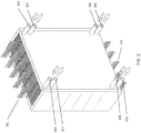
- FIG. 1 depicts a new type of liquid desiccant system as described in more detail in U.S. Patent Application Publication No. US 20120125020 .
- a conditioner 101 comprises a set of plate structures that are internally hollow.
- a cold heat transfer fluid is generated in cold source 107 and entered into the plates.
- Liquid desiccant solution at 114 is brought onto the outer surface of the plates and runs down the outer surface of each of the plates.
- the liquid desiccant runs behind a thin membrane that is located between the air flow and the surface of the plates.
- Outside air 103 is now blown through the set of (wavy) conditioner plates.
- the liquid desiccant on the surface of the plates attracts the water vapor in the air flow and the cooling water inside the plates helps to inhibit the air temperature from rising.
- the treated air 104 is put into a building space.
- the liquid desiccant is collected at the bottom of the wavy conditioner plates at 111 and is transported through a heat exchanger 113 to the top of the regenerator 102 to point 115 where the liquid desiccant is distributed across the wavy plates of the regenerator.
- Return air or optionally outside air 105 is blown across the regenerator plate and water vapor is transported from the liquid desiccant into the leaving air stream 106.
- An optional heat source 108 provides the driving force for the regeneration.
- the hot transfer fluid 110 from the heat source can be put inside the wavy plates of the regenerator similar to the cold heat transfer fluid on the conditioner.
- the liquid desiccant is collected at the bottom of the wavy plates 102 without the need for either a collection pan or bath so that also on the regenerator the air flow can be horizontal or vertical.
- An optional heat pump 116 can be used to provide cooling and heating of the liquid desiccant. It is also possible to connect a heat pump between the cold source 107 and the hot source 108, which is thus pumping heat from the cooling fluids rather than the desiccant.
- FIG. 2 describes a 3-way heat exchanger as described in further detail in U.S. Patent Application Serial Nos. 13/915,199 filed on June 11, 2013 , 13/915,222 filed on June 11, 2013 , and 13/915,262 filed on June 11, 2013 .
- a liquid desiccant enters the structure through ports 304 and is directed behind a series of membranes as described in FIG. 1 . The liquid desiccant is collected and removed through ports 305.
- a cooling or heating fluid is provided through ports 306 and runs counter to the air stream 301 inside the hollow plate structures, again as described in FIG. 1 and in more detail in FIG. 3 . The cooling or heating fluids exit through ports 307.
- the treated air 302 is directed to a space in a building or is exhausted as the case may be.
- the figure illustrates a 3-way heat exchanger in which the air and heat transfer fluid are in a primarily vertical orientation. It is however also possible to flow the air and the heat transfer fluid in a horizontal aspect, which is not fundamental to the operation of
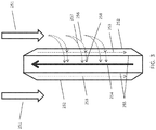
- FIG. 3 describes a 3-way heat exchanger as described in more detail in U.S. Provisional Patent Applications Serial No. 61/771,340 filed on March 1, 2013 .
- the air stream 251 flows counter to a cooling fluid stream 254.
- Membranes 252 contain a liquid desiccant 253 that is falling along the wall 255 that contain a heat transfer fluid 254.
- Water vapor 256 entrained in the air stream is able to transition the membrane 252 and is absorbed into the liquid desiccant 253.
- the heat of condensation of water 258 that is released during the absorption is conducted through the wall 255 into the heat transfer fluid 254.
- Sensible heat 257 from the air stream is also conducted through the membrane 252, liquid desiccant 253 and wall 255 into the heat transfer fluid 254.
- FIG. 4A illustrates a schematic representation of a liquid desiccant air conditioner system as more fully described in application U.S. Patent Application Publication No. 20140260399 .
- a 3-way conditioner 403 (which is similar to the conditioner 101 of FIG. 1 ) receives an air stream 401 from a room or from the outside ("RA"). Fan 402 powered by electricity 405 moves the air 401 through the conditioner 403 wherein the air is cooled and dehumidified in a summer cooling mode. The resulting cool, dry air 404 ("SA”) is supplied to a space for occupant comfort.
- the 3-way conditioner 403 receives a concentrated desiccant 427 in the manner explained under FIGS. 1-3 .
- a membrane on the 3-way conditioner 403 it is preferable to use a membrane on the 3-way conditioner 403 to ensure that the desiccant is generally fully contained and is unable to get distributed into the air stream 404.
- the diluted desiccant 428 which now contains the captured water vapor is transported to the regenerator 422 which is generally located outdoor.
- chilled heat transfer fluid (usually water) 409 is provided by pump 408, and enters the conditioner module 403 where it picks up sensible heat from the air as well as latent heat released by the capture of water vapor in the desiccant.
- the warmer water 406 is also brought outside to the heat exchanger 407 which connects to the chiller system 430. It is worth noting that unlike the conventional mini-split system of FIGS.
- the system of FIG. 4A and FIG. 4B has no high pressure lines between the indoor unit 403 and the outdoor unit, the lines between the indoor and outdoor system of FIG. 5A are all low pressure water and liquid desiccant lines.
- the system of FIG. 4A does not require a condensate drain line like line 507 in FIG. 5A . Rather, any moisture that is condensed into the desiccant is removed as part of the desiccant itself. This also eliminates problems with mold growth in standing water that can occur in the conventional mini-split systems of FIGS. 5A and 5B .
- the liquid desiccant 428 leaves the conditioner 403 and is moved through the optional heat exchanger 426 to the regenerator 422 by pump 425. If the desiccant lines 427 and 428 are relatively long they can be thermally connected to each other, which eliminates the need for heat exchanger 426.
- the chiller system 430 comprises a water to refrigerant evaporator heat exchanger 407 which cools the circulating cooling fluid 406.
- the liquid, cold refrigerant 417 evaporates in the heat exchanger 407 thereby absorbing the thermal energy from the cooling fluid 406.
- the gaseous refrigerant 410 is now re-compressed by compressor 411.
- the compressor 411 ejects hot refrigerant gas 413, which is liquefied in the condenser heat exchanger 415.
- the liquid refrigerant 414 then enters expansion valve 416, where it rapidly cools and exits at a lower pressure.
- the chiller system 430 can be made very compact since the high pressure lines with refrigerant (410, 413, 414 and 417) only have to run very short distances. Furthermore, since the entire refrigerant system is located outside of the space that is to be conditioned, it is possible to utilize refrigerants that normally cannot be used in indoor environments such as by way of example, CO 2 , Ammonia and Propane. These refrigerants are sometimes preferable over the commonly used R410A, R407A, R134A because of their lower greenhouse gas potential or over R1234YF and R1234ZE refrigerants, but they are undesirable indoor because of flammability or suffocation or inhalation risks.
- the condenser heat exchanger 415 now releases heat to another cooling fluid loop 419 which brings hot heat transfer fluid 418 to the regenerator 422.
- Circulating pump 420 brings the heat transfer fluid back to the condenser 415.
- the 3-way regenerator 422 thus receives a dilute liquid desiccant 428 and hot heat transfer fluid 418.
- a fan 424 powered by electricity 420 brings outside air 421 ("OA") through the regenerator 422. The outside air picks up heat and moisture from the heat transfer fluid 418 and desiccant 428 which results in hot humid exhaust air (“EA”) 423.
- EA hot humid exhaust air
- the compressor 411 receives electrical power 412 and typically accounts for 80% of electrical power consumption of the system.
- the fan 402 and fan 424 also receive electrical power 405 and 429 respectively and account for most of the remaining power consumption.
- Pumps 408, 420 and 425 have relatively low power consumption.
- the compressor 411 will operate more efficiently than the compressor 510 in FIG. 5A for several reasons: the evaporator 407 in FIG. 4A will typically operate at higher temperature than the evaporator coil 501 in FIG. 5A because the liquid desiccant will condense water at much higher temperature without needing to reach saturation levels in the air stream. Furthermore the condenser 415 in FIG. 4A will operate at lower temperatures than the condenser coil 516 in FIG. 5A because of the evaporation occurring on the regenerator 422 which effectively keeps the condenser 415 cooler. As a result the system of FIG. 4A will use less electricity than the system of FIG. 5A for similar compressor isentropic efficiencies.
- FIG. 4B shows essentially the same system as FIG. 4A except that the compressor 411's refrigerant direction has been reversed as indicated by the arrows on refrigerant lines 414 and 410.
- Reversing the direction of refrigerant flow can be achieved by a 4-way reversing valve (which will be shown in FIG. 5A and FIG. 5B ) or other convenient means.
- FIG. 5A illustrates a schematic diagram of a conventional mini-split air conditioning system as is frequently installed in buildings operating in a summer cooling mode.
- the unit comprises a set of indoor components that generate cool, dehumidified air and a set of outdoor components that release heat to the environment.
- the indoor components comprise a cooling (evaporator) coil 501 through which a fan 502 blows air 503 from the room.
- the cooling coil cools the air and condenses water vapor on the coil which is collected in drain pan 506 and ducted to the outside 507.
- the resulting cooler, drier air 504 is circulated into the space and provides occupant comfort.
- the cooling coil 501 receives liquid refrigerant at pressure of typically 50-200 psi through line 526, which has already been expanded to a low temperature and pressure by open expansion valve 525-O.
- the pressure of the refrigerant in line 523 before the expansion valve 525-O is typically 300-600psi.
- the cold liquid refrigerant 526 enters the cooling coil 501 where it picks up heat from the air stream 503.
- the heat from the air stream evaporates the liquid refrigerant in the coil and the resulting gas is transported through line 509 to the outdoor components and more specifically to the compressor 510 where it is re-compressed to a high pressure of typically 300-600psi.
- the system can have multiple cooling coils 501, fans 502 and expansion valves 525-O, for example a number of individual cooling coil assemblies could be located in various rooms that need to be cooled.
- the outdoor components comprise a condenser coil 516 and a condenser fan 517 as well as a four-way valve assembly 511.
- the four-way valve 512 (which for convenience has been labeled the 512-"A" position) has been positioned inside the valve body 511 so that the hot refrigerant 513 is directed to the condenser coil 516 through line 515.
- the fan 517 blows outside air 518 through the condenser coil 516 where it picks up heat from the compressor 510 which is rejected to the air stream 519.
- the cooled liquid refrigerant 520 is conducted to a set of valves 521, 522, 524 and 525, with the addition of an "O" for open or a "C" for closed.
- the refrigerant 520 goes through the check valve 521-O and bypasses the expansion valve 522-C. Since the second check valve 524-C is closed, the refrigerant moves through line 523 and to the second expansion valve 525-O in which the refrigerant expands and cools.
- the cold refrigerant 526 is then conducted to the evaporator 501 where it picks up heat and expands back to a gas.
- the gas 509 is then conducted to the 4-way valve 511 and flows back to the compressor 510 through line 514.
- the system can have multiple compressors or multiple condenser coils and fans.
- the primary electrical energy consuming components are the compressor 510, the condenser fan 516 and the evaporator fan 502.
- the compressor uses close to 80% of the electricity required to operate the system, with the condenser and evaporator fans taking about 10% of the electricity each.
- FIG. 5B illustrates a conventional mini-split system operating in winter heating mode.
- the main difference with FIG. 5A is that the valve 512 in the 4-way valve body 511 has been moved to the "B" position. This directs the hot refrigerant to the indoor evaporator coil which becomes in effect the condenser coil.
- the valves 521, 522, 524 and 525 also switch position and the refrigerant now flows through check valve 524-O and expansion valve 522-O while expansion valve 525-C and check valve 521-C are closed.
- the refrigerant picks up heat from the outside air 518 before being returned through valve body 511 and valve 512-B to the compressor 510.
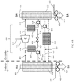
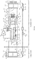
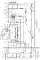
- FIG. 6A illustrates an alternate description of a mini-split liquid desiccant system set up in a summer cooling and dehumidification mode.
- a 3-way liquid desiccant conditioner 603 receives an air stream 601 which is moved by fan 602 through the conditioner 603. The treated air 606 is directed into the space.
- the conditioner 603 receives concentrated liquid desiccant 607 which, as explained in FIG. 2 and FIG. 3 , picks up moisture from the air stream 601.
- the diluted liquid desiccant 608 can now be directed to a small reservoir 610.
- Pump 609 brings concentrated desiccant 607 from the reservoir 610 back to the conditioner 603.
- Dilute desiccant 611 is moved to reservoir 648 where it can be directed to the regenerator 643.
- Concentrated desiccant 612 from the regenerator 643 is added to the reservoir 610.
- the conditioner 603 receives a heat transfer fluid 604 which can be either cold or hot.
- the heat transfer fluid leaves the conditioner 603 at line 605 and is circulated by pump 613 through fluid to refrigerant heat exchanger 614 where the fluid is either cooled or heated.
- the exact setup of pumps 609 and 613 and of reservoir 610 is not fundamental to the description of this system and can be varied based on the exact application and installation.
- Refrigerant compressor 615 compresses a refrigerant gas to high pressure and the resulting hot refrigerant 616 is directed to a 4-way valve assembly 617.
- the valve 618 is in the "A" position as before labeled 618-A in the figure. In this position the hot refrigerant gas is directed through line 619 to two heat exchangers: a refrigerant to liquid heat exchanger 620, and a refrigerant to air heat exchanger 622 through 3-way switching valve 621-A also in the "A" position which directs the refrigerant to the heat exchanger 622.
- the refrigerant leaves the heat exchanger 622 through 3-way switching valve 626-A which is also in an "A" position, which directs the refrigerant through line 627.
- the refrigerant from heat exchanger 620 is combined and both streams flow to a set of valves 628, 629, 630 and 631.
- the check valve 628-O is open and allows the refrigerant to flow to expansion valve 631-O which expands the liquid refrigerant to become cold in line 632.
- Check valve 630-C is closed as is expansion valve 629-C.
- the refrigerant next encounters another 3-way switching valve 633-A in the "A" position.
- the cold refrigerant now picks up heat in the aforementioned heat exchanger 614.
- the warmer refrigerant then moves through line 634 to the 4-way valve 617, where it is directed back to the compressor 615 through line 635.
- the liquid to refrigerant heat exchanger 620 is supplied with a heat transfer fluid (usually water) through line 639 by pump 638.
- the heated heat transfer fluid is then directed through line 640 to a regenerator membrane module 643, which is similar in construction as the module from FIG. 2 .
- the regenerator module 643 receives an air stream 641 through fan 642.
- the air stream 641 is now heated by the heat transfer fluid and picks up moisture from the diluted liquid desiccant 645 which results in a hot, moist exhaust air stream 644.
- Pump 647 moves the diluted liquid desiccant from reservoir 648 to the membrane module 643 and re-concentrated liquid desiccant 646 is moved back to the reservoir 648.
- a small pump 649 can provide desiccant flow between the reservoirs 610 and 648.
- an air stream 624 is directed by fan 623 through the air to refrigerant heat exchanger 622.
- the air stream 624 is sensibly heated by the refrigerant and the resulting hot air 625 constitutes a second exhaust stream.
- Refrigerant line 637 is inactive in this summer cooling mode and its use will be described under FIG. 6C .
- desiccant lines 611 and 612 thermally connect desiccant lines 611 and 612 and form a heat exchanger between the two lines so that heat from the regenerator 643 is not conducted directly to the conditioner 603, which will reduce the energy load on the conditioner.
- a separate liquid desiccant to liquid desiccant heat exchanger 650 instead of thermally connecting lines 611 and 612.
- An optional water injection system 651 (which is further described in U.S. Patent Application No. 14/664,219 ) prevents overconcentration of the desiccant in certain conditions by adding water 652 to the desiccant, which also can have the effect of making the system more energy efficient.
- FIG. 6B the system of FIG. 6A has been switched to a winter heating and humidification mode.
- the valve 618 has been switched from the “A" to the "B" position, which results in reversal of the refrigerant flow through the circuits in such a way that heat exchanger 614 now receives hot refrigerant whereas heat exchangers 622 and 620 receive cold refrigerant.
- Valve 628-C is now closed, expansion valve 629-O is open, valve 630-O is open and expansion valve 631-C is closed.
- the refrigerant system is pulling heat from air streams 641 and 624 and directing it to the conditioner 603 which is now providing heated, moist air to the space.
- the liquid desiccant is delivering moisture to the space and thus is getting more concentrated in the conditioner 603.
- the liquid desiccant is pulling moisture from the air stream 641.
- U.S. Patent Application No. 61/968,333 filed March 20, 2014 describes a method to add water to the liquid desiccant to prevent this from happening as will be shown in FIG. 9B .
- This method could also be applied here and water could be injected for example in line 611.
- the air stream 624 may at some temperatures get overly cold and ice could start forming on heat exchanger 622. In such a situation it would be possible to shut down the fan 623 and instead have all heat and moisture be taken out by regenerator 643.
- FIG. 6C shows the same system of FIG. 6A and 6B , with the difference that in this special operating mode the indoor conditioner unit is 603 is set up so that it provides heating and dehumidification of the air stream.
- This operating mode is particularly useful in seasons where the outside air is cold and the humidity is high such as the rainy season known in Asia as the plum-rain season.
- This mode is achieved by switching the valve 618 into the "A” position, and switching the 3-way refrigerant valves 621, 626 and 633 from the "A" to the "B” position.
- the hot refrigerant now takes a different path: after exiting valve 618-A it is directed through line 619, and heat exchanger 620.
- valve 621-B is in the "B" position, no hot refrigerant will flow through heat exchanger 622. Instead the refrigerant flows through valves 628-O and expansion valve 631-O where it is cooled.
- Valve 633-B is now in the "B” position and directs the cold refrigerant to line 637 where it reaches valve 626-B also now in the "B” position. The cold refrigerant thus enters the heat exchanger 622 where it is able to pick up heat from air stream 624.
- Valve 621-B which is also in the "B” position, now directs the warmer refrigerant gas leaving the heat exchanger 622 to line 619 and 635 where it returns to the compressor 615.
- This configuration effectively pumps heat through the refrigerant system from heat exchanger 622 to heat exchanger 620, thereby producing hot heat transfer fluid through line 639 which thus allows the regenerator 643 to receive hot heat transfer fluid and produce more concentrated desiccant 646. Since the heat exchanger 614 is not receiving any refrigerant and is in effect inactive, pump 613 can be shut down and the conditioner module 603 no longer receives any heat transfer fluid. As a result the air stream 601 is now exposed to the concentrated desiccant 607 but because of the lack of heat transfer fluid flow through line 605, the air will dehumidify adiabatically and warm, dry air 606 will exit the conditioner.
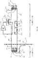
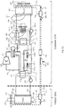
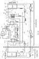
- FIG. 7A illustrates a different description of a mini-split liquid desiccant system set up in a summer cooling and dehumidification mode.
- a 3-way liquid desiccant conditioner 703 receives an air stream 701 which is moved by fan 702 through the conditioner 703.
- the treated air 706 is directed into the space.
- the conditioner 703 receives concentrated liquid desiccant 707 which, as explained in FIG. 2 and FIG. 3 , picks up moisture from the air stream 701.
- the diluted liquid desiccant 708 can now be directed to a small reservoir 710.
- Pump 709 brings concentrated desiccant 707 from the reservoir 710 back to the conditioner 703.
- Dilute desiccant in line 711 is moved to reservoir 754 where it can be directed to the regenerator 748.
- Concentrated desiccant in line 712 from the regenerator 748 is added to the reservoir 710 by pump 755.
- the conditioner 703 receives a heat transfer fluid 704 which can be either cold or hot.
- the heat transfer fluid leaves the conditioner 703 at line 705 and is circulated by pump 713 through fluid to refrigerant heat exchanger 714 where the fluid is either cooled or heated.
- the exact setup of pumps 709, 713 and 755 and of reservoir 710 and 754 is not fundamental to the description of this system and can be varied based on the exact application and installation.
- desiccant lines 711 and 712 thermally connect desiccant lines 711 and 712 and form a heat exchanger between the two lines so that heat from the regenerator 748 is not conducted directly to the conditioner 703, which will reduce the energy load on the conditioner.
- a separate liquid desiccant to liquid desiccant heat exchanger 756 instead of thermally connecting lines 711 and 712.
- An optional water injection system 757 (which is further described in U.S. Patent Application No. 14/664,219 ) prevents overconcentration of the desiccant in certain conditions by adding water 758 to the desiccant, which also can have the effect of making the system more energy efficient.
- Refrigerant compressor 715 compresses a refrigerant gas to high pressure and the resulting hot refrigerant 716 is directed to a 4-way valve assembly 717.
- the valve 718 is in the "A" position as before, and is labeled 718-A in the figure.
- the hot refrigerant gas is directed through line 719 to a refrigerant-to-liquid heat exchanger 720.
- the refrigerant leaves the heat exchanger 720 and is directed through line 721 to a second 4-way valve assembly 722 with the valve 723-A in an "A" position, which directs the refrigerant through line 724 and subsequently to condenser coil 725.
- Condenser coil 725 receives an air stream 726 moved by fan 727 resulting in a heated exhaust air stream 728.
- the cooler refrigerant leaves the coil 725 through line 729 and is directed to the open valve 730-O.
- Expansion valve 731-C is closed and inactive in this operating mode.
- the refrigerant moves back to 4-way valve 722 through line 732 and is directed through line 733 and line 736 to expansion valve 738-O which expands the refrigerant.
- Check valve 737-C is closed and inactive.
- the cold refrigerant enters the heat exchanger 714 through line 739 and removes heat from the heat transfer fluid on the opposite side of the heat exchanger 714.
- the warmer refrigerant is then moved through line 740 and 741 to 4-way valve 717 where it is directed through line 742 back to the compressor 715.
- Line 734 and valve 735-C are inactive or closed respectively.
- the refrigerant to liquid heat exchanger 720 receives a heat transfer fluid (usually water or a water/glycol mixture but generally any heat transfer fluid will do) pumped by pump 743 through line 744.
- a heat transfer fluid usually water or a water/glycol mixture but generally any heat transfer fluid will do
- the heat from the compressed refrigerant in line 719 is transferred in the heat exchanger 720 to the heat transfer fluid and the hot heat transfer fluid is directed through line 745 to a set of regenerator plates 748 similarly constructed to those as described in FIG. 2 and FIG. 3 .
- the hot heat transfer fluid drives moisture out of the weak desiccant that is directed to the regenerator 748 by pump 753 through weak desiccant supply line 751.
- Air 746 is blown by fan 747 through the regenerator module 748 and results in hot, humid air 749 being exhausted from the system.
- the concentrated desiccant exiting the regenerator 748 is directed through line 752 to an optional collection tank 754. From there the concentrated desiccant
- the system of FIG. 7A is able to provide sensible cooling and dehumidification at a much higher temperature as a conventional mini-split system. As a result, the indoor room will feel drier and more comfortable than what a conventional system will be able to deliver and the system will do this with less lift (the difference in temperature of refrigerant across the compressor 715) as a conventional system would have.
- FIG. 7B shows the system of FIG. 7A in a winter heating and humidification mode.
- Valve 718 has been placed in the "B" position resulting in a different direction of the refrigerant flow: the hot refrigerant leaving the compressor 715 through line 716 is now directed through line 741 to heat exchanger 714.
- the cooler refrigerant is now directed through line 739, 736 and 733 to valve 722 which is still in the "A" position as before.
- the refrigerant is expanded and cooled in expansion valve 731-O and the cold refrigerant is directed to coil 725, back through valve 722 and to heat exchanger 720 before returning through lines 721, valve 717 and line 742 to the compressor 715.
- the advantage of this setup is that the system now provides moist, warm air to the space which will prevent the space from becoming too dry as is the case with conventional mini-split heat pump air conditioners. This will add to user comfort since conventional air conditioning heat pumps only provide heat unless a separate humidifier is used.
- the other advantage of this system is that in winter the heat can be primarily pumped from the regenerator module 748.
- this module Since this module only has desiccant and heat transfer fluid, it will be able to operate at much lower temperatures than the condenser coil of a conventional heat pump system, which starts to have ice formation when the outside air temperatures reaches 32F and the relative humidity is near 100%. Conventional heat pumps in that case will temporarily reverse cycle so that ice can be removed from the coil, meaning that they are cooling the space for a little while in reverse cycle mode. This obviously is not very energy efficient.
- the system of FIG. 7B will not have to reverse cycle if the liquid desiccant concentration is kept at concentrations of approximately 20-30%. This is possible in general as long as there is enough moisture in the outside air.
- FIG. 7C illustrates in a similar way as FIG. 6C a special mode that allows for the indoor space to be heated as well as dehumidified. This would occur when outdoor conditions are cold and very humid, as is for example the case on rainy early spring days. In mainland China this is known as the plum rain season and conditions during that time of year result in very humid and cold indoor conditions, leading to mold problems and health issues.
- the system is set up as in FIG. 7A , but with the second 4-way valve 722 in the "B" position and bypass valve 735 in the open position indicated as 735-O in the figure.
- the hot refrigerant from the compressor 715 is directed through line 716, valve 717 and line 719 to heat exchanger 720 where heat is removed into the circulating heat transfer fluid loop 744, 745.
- the condensed refrigerant is then directed through line 721 into valve 722 which has been set in the "B" position, which directs the refrigerant to expansion valve 731-C in which it is expanded and cooled.
- the fan 727 now moves air through coil 725 which allows the refrigerant to pick up heat and the evaporated refrigerant is directed through line 724, valve 722 and line 733 and 734 through bypass valve 735-O and valve 717 back to the compressor 715.
- the liquid desiccant flowing through regenerator 748 is regenerated by the hot heat transfer fluid circulating through the heat exchanger 720 and the regenerator 748.
- Concentrated desiccant is directed back to the indoor conditioner 703 where it again picks up moisture.
- conditioner 703 is not receiving a cold heat transfer fluid because the refrigerant circuit bypasses heat exchanger 714 through the valve 735-O.
- the pump 713 can thus be shut down if desired.
- the desiccant in conditioner 703 will pick up moisture from the air stream 701 which results in adiabatic heating of the air stream and resulting leaving air 706 that is drier and warmer than the air entering and thus results in simultaneous heating and dehumidification.
- the space is heated and dehumidified and the compressor is used solely to generate concentrated desiccant to be used by the conditioner. Since the amount of regeneration heat is only proportional to the amount of moisture removed by the conditioner and some components like pump 713 are inactive, this is a very efficiency method of providing dehumidification and heating. It is of course also possible to develop other refrigerant circuits or split the refrigerant circuit into multiple circuits in which some provide active heating and others provide cooling.
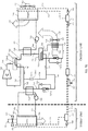
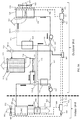
- FIG. 8A illustrates a hybrid approach between the system of FIG. 6A and that of FIG. 7A .
- the coil 833 (similar to coil 622 in FIG. 6A and 725 in FIG. 7A ) is kept on the heat transfer fluid side thereby allowing hot heat transfer fluid to be directed either to the regenerator plates 843 or to the conditioner plates 803.
- an air stream 801 from the space is directed by fan 802 to a set of membrane conditioner plates 803 such as were earlier described in FIG. 2 and FIG. 3 .
- the conditioner 803 provides an air treatment function and delivers a supply air stream 806 to the space.
- the conditioner 803 receives a heat transfer fluid (cold in FIG.
- conditioner 803 through line 804, which allows conditioner 803 to cool and dehumidify the air stream 801.
- the warmer heat transfer fluid is directed through line 805, valve 814A (in the "A") position and through pump 813 to heat exchanger 816 where it is cooled by a cold refrigerant.
- the colder heat transfer fluid is then directed through valve 815-A in the "A" position back to conditioner 803.
- conditioner 803 also receives a concentrated liquid desiccant through line 807 which allows the conditioner to absorb moisture from air stream 801 as described elsewhere.
- the diluted desiccant is directed through line 808 to an optional collection tank 810. Concentrated desiccant is pumped from tank 810 by pump 809 back to the conditioner module 803.
- a compressor 818 provides hot refrigerant gas through line 819 to reversing valve housing 820 with valve 821-A in the "A" position.
- the hot gas is directed through line 823 to heat exchanger 824 which heats a heat transfer fluid flowing through line 840 and 831.
- the condensed gas flows through open check valve 826-O while expansion valve 827-C is closed.
- the refrigerant then flows through expansion valve 829-O where it expands and cools while check valve 828-C is closed.
- the cold refrigerant now is directed through heat exchanger 816 where is absorbs heat from the heat transfer fluid on the opposite site.
- the warmed refrigerant is then transported back through line 830 and valve 820 to the compressor 818 through line 822.
- the hot heat transfer fluid flowing through lines 840 and 831 is picking up heat from the refrigerant in heat exchanger 824.
- the hot fluid is directed to regenerator 843 which receives an air stream 841 through fan 844 resulting in a hot exhaust air stream 849.
- Pump 839 moves the heat transfer fluid through line 840 and optionally through line 837 and valve 838-A in the "A" position so the heat transfer fluid is either cooled by air stream 835 and fan 834 in coil 833 resulting in a hot exhaust air stream 836, or simply flowing through line 840 back to the heat exchanger 824.
- Valve 832A is also in the "A" position and simply directs the cooled heat transfer fluid back into the fluid line 831.
- the regenerator 843 also receives a diluted, or weak desiccant through line 844 which is re-concentrated by means of the heat transfer fluid coming in through line 831.
- the re-concentrated desiccant is directed through line 846 into optional desiccant tank 847.
- Pump 845 removes some diluted desiccant and moves it to the regenerator 843 through line 844. Lines 817 and 850 are not used in this mode.
- FIG. 8B shows the system in FIG. 8A in a winter heating and humidification mode.
- the refrigerant valve 821-B has changed from its "A" position to its "B” position.
- the heat transfer fluid loops are unchanged in this operating mode.
- the hot refrigerant flows from the compressor 818 through line 819 to valve housing 820 into heat exchanger 816.
- the resulting hot heat transfer fluid in line 804 drives the conditioner to heat and humidify the air 801 in the space.
- the condensed refrigerant now enters check valve 828-A, flows to expansion valve 827-O which expands and cools the refrigerant.
- the cold refrigerant then is directed to heat exchanger 824 where it picks up heat from the heat transfer fluid flowing on the opposite side in lines 840 and 831.
- heat is transferred ultimately from the outside air streams 841 and 835 to the indoor space air stream 806.
- the desiccant in line 844 also picks up moisture from air stream 841 resulting in a weaker desiccant that subsequently makes its way to the conditioner where it helps humidify the air stream 806.
- the lines 817 and 840 are not active.
- FIG. 8C illustrates an alternate operating mode wherein refrigerant valve 821 is in the "A" position as in FIG. 8A .
- Hot refrigerant is again directed to heat exchanger 824 and the heat transfer fluid on the opposite side in line 840 is again heated and directed to the regenerator 843.
- valves 814, 815, 832 and 838 have all been switched into their “B” positions. This allows the hot heat transfer fluid to be directed from the regenerator solely back to the refrigerant to liquid heat exchanger 824, but not to coil 833. Instead coil 833 receives cold heat transfer fluid created in heat exchanger 816, which is directed by pump 813 through lines 850 and 817 to the coil 833.
- the system is effectively pumping heat between heat exchanger 816 which is coupled by the cold heat transfer fluid to coil 833 and heat exchanger 824 which is coupled by the hot heat transfer fluid to the regenerator.
- heat exchanger 816 which is coupled by the cold heat transfer fluid to coil 833
- heat exchanger 824 which is coupled by the hot heat transfer fluid to the regenerator.
- the indoor air 801 being dehumidified by the concentrated desiccant supplied through line 807, and since no heat transfer fluid is flowing through line 804, this dehumidification will in effect be almost adiabatic resulting in a warm, dry air stream 806.
- the diluted desiccant can be transported to the regenerator 843 as described before, where the heat of the hot heat transfer fluid causes the desiccant to re-concentrate. It should be clear to those experienced in the art that other water and desiccant circuits can easily be derived that accomplish the same or similar functions.
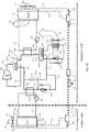
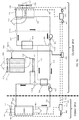
- FIG. 9A illustrates a hybrid approach between the system of FIG. 8A but replaces the refrigerant compressor system with a cooling tower or a geothermal loop and a hot water source.
- an air stream 901 from the space is directed by fan 902 to a set of membrane conditioner plates 903 such as were earlier described in FIG. 2 and FIG. 3 .
- the conditioner 903 provides an air treatment function and delivers a supply air stream 906 to the space.
- the conditioner 903 receives a heat transfer fluid (cold in FIG. 9A ) through line 904, which allows conditioner 903 to cool and dehumidify the air stream 901.
- the warmer heat transfer fluid is directed through line 905, pump 913, heat exchanger 914 where it can be cooled or heated by a heat transfer fluid on the opposite side (however in this mode the heat transfer fluid in line 923 and line 922 is not running), and valve 915A (in the "A") position which directs the heat transfer fluid through a cooling tower basin 921, wherein the heat transfer fluid is cooled.
- the colder heat transfer fluid is then directed through line 904 back to conditioner 903.
- conditioner 903 also receives a concentrated liquid desiccant through line 907 which allows the conditioner to absorb moisture from air stream 901 similar to what was described before.
- the diluted desiccant is directed through line 908 to an optional collection tank 910.
- Concentrated desiccant is pumped from tank 910 by pump 909 back to the conditioner module 903. Weak, or diluted desiccant is directed through line 911 to optional tank 933 and concentrated desiccant is removed from tank 933 by pump 934 and delivered through line 912 back to tank 910.
- the cooling tower contains a wetting media 917 and also contains a basin 921 which provides cold water as well as an air intake 916 and fan 918 and an exhaust air stream 920.
- Make-up water is provided through line 919 and an optional valve 941-A which in the "A" position directs the make-up water to the cooling tower wetting media 917.
- Valve 941-A can also be switched to deliver water to a water injection unit 942, which can be used to add water to the liquid desiccant flowing in line 912.
- a water injection system is further described in U.S. Patent Application No. 14/664,219 and is used to control the desiccant concentration particularly in dry conditions.
- Valve 941-A could also be replaced with two individual valves if water needs to be delivered to the cooling tower or injection unit at the same time which can be used in hot, dry conditions.
- the cooling tower could be replaced with a geothermal loop, in which the heat transfer fluid of line 904 is simply pumped through a geothermal heat exchanger, which is commonly located in the ground or river or lake near the facility where the system is located.
- the regenerator 926 receives a hot heat transfer fluid 925 from a heat source 924, which can be any convenient heat source such as a gas-fired water heater, solar hot water system or waste heat collection system. Valve 940-A in the "A" position directs the hot heat transfer fluid 925 to the regenerator 926.
- the cooler hot heat transfer fluid 936 that is leaving the regenerator is pumped by pump 937 the valve 938-A in the "A" position through line 939 back to the heat source 924.
- the regenerator 926 also receives a dilute (weak) desiccant through line 930 as well as an air stream 927 moved by fan or blower 928 resulting in a hot, humid exhaust air stream 929.
- the re-concentrated desiccant flows through line 932 back to tank 933from where it is send to the conditioner 903 where it is re-used.
- the indirect evaporative cooling system 943 provides additional sensible cooling if desired and receives water 944 from the water supply line 919.
- the IEC may also be used in the various other described systems disclosed herein to provide additional sensible cooling to the supply air stream.
- FIG. 9B shows the system of FIG. 9A in a winter operating mode.
- Valves 915-B, 941-B, 940-B and 938-B have all been switched into their "B" positions.
- Hot heat transfer fluid from heater 924 is diverted by valve 940-B to pump 937 without going to membrane regenerator 926.
- Valve 938-B directs the hot heat transfer fluid through line 923 to heat exchanger 924 wherein it heat the heat transfer fluid 905 which is pumped by pump 913.
- the warmer heat transfer fluid leaving heat exchanger 914 is directed by valve 915-B to the conditioner 903 which in turn results in air stream 906 being warm and moist.
- the other side of heat exchanger 914 directs its cooler heat transfer fluid through line 922 back to heater 924 wherein it gets heated again.
- Concentrated desiccant in line 908 is now directed through optional tank 910 through line 911 to tank 933 where it is pumped by pump 931 to the regenerator.
- the regenerator will allow the desiccant to absorb moisture assuming that the air stream 927 has enough moisture in it and diluted desiccant will flow through line 932 and tank 933, pump 934 and water injection unit 942 to line 912 back to tank 910 where it can be directed to the conditioner 903 and continue to moisten the air stream 906.
- the water injection module 942 can be used to add water to the desiccant and to eventually moisten the air stream 906 as described more fully in U.S. Patent Application No. 61/968,333 .
- FIG. 9C shows the system of FIG. 9A in a mode wherein the system provides but heating of air stream 901/906 as well as dehumidification.
- Valve 940-A is kept in the "A" position as in FIG. 9A and valves 915-B, 938-B and 941-B are kept in their “B” positions.
- Hot heat transfer fluid from heater 924 now flows through valve 940-A to the regenerator 926.
- the hot heat transfer fluid results in a hot moist air stream 929 and a concentrated desiccant in line 932, which is directed back through tank 933 and pump 934 through water injection module 942 (inactive) and tank 910 to conditioner 903.
- the concentrated desiccant is able to absorb moisture from air stream 901.
- valve 938-B the cooler hot heat transfer fluid is directed by valve 938-B to heat exchanger 914, resulting in a flow of warm heat transfer fluid through line 904 to the conditioner module. It is of course also possible to switch valve 938-B to the "A" position which would result in the heat transfer fluid bypassing the heat exchanger 914.
- the pump 913 can then be switched off and conditioner 903 would function as an adiabatic heating system and only desiccant would be provided to the conditioner 903.
- the cooling tower wetting media assembly (917) can also be replaced with a set of membrane modules similar to the conditioner membrane modules as is shown in FIG. 9D in a summer cooling mode.
- the heat transfer fluid from the pump 913 is directed to the 3-way membrane module which is similar as described in FIG. 2 and 3 .
- Valve 915-A directs the heat transfer fluid to the evaporative membrane module 945. Water for evaporation is again provided through line 919 and excess water can drain out through line 946. Since both the evaporative module 945 and the water injection module 942 contain membranes, it is now possible to use seawater or waste water for the evaporation function.
Claims (15)
- Klimaanlage mit flüssigem Trocknungsmittel, die in einem Kühl- und Entfeuchtungsmodus, einem Heiz- und Befeuchtungsmodus und/oder einem Heiz-und Entfeuchtungsmodus betrieben werden kann, wobei das System Folgendes umfasst:einen Konditionierer (803) zum Behandeln eines ersten Luftstroms (801), der ihn durchfließt und in einen Raum abgegeben wird, wobei der genannte Konditionierer (803) eine Wärmeträgerflüssigkeit und ein flüssiges Trocknungsmittel zum Kühlen und Entfeuchten des ersten Luftstroms (801) im Kühl- und Entfeuchtungsmodus, zum Heizen und Befeuchten des ersten Luftstroms (801) im Heiz- und Befeuchtungsmodus und zum Heizen und Entfeuchten des ersten Luftstroms (801) im Heiz- und Entfeuchtungsmodus benutzt;einen Regenerator (843), der so mit dem Konditionierer (803) verbunden ist, dass das flüssige Trocknungsmittel zwischen dem Regenerator (843) und dem Konditionierer (803) zirkuliert werden kann, wobei der Regenerator (843) bewirkt, dass das flüssige Trocknungsmittel Wasserdampf in einen zweiten Luftstrom (841) im Kühl- und Entfeuchtungsmodus und im Heiz- und Entfeuchtungsmodus desorbiert, und bewirkt, dass das flüssige Trocknungsmittel Wasserdampf aus dem zweiten Luftstrom (841) im Heiz- und Befeuchtungsmodus absorbiert;ein Kühlmittelsystem mit einem Kompressor (818) und wenigstens einem ein Kühlmittel verarbeitenden Expansionsventil (827, 829);einen ersten Kühlmittel-Wärmeträgerflüssigkeit-Wärmetauscher (816), der mit dem Konditionierer (803) und dem Kühlmittelsystem zum Austauschen von Wärme zwischen dem vom Kühlmittelsystem erhitzten oder gekühlten Kühlmittel und der im Konditionierer (803) benutzten Wärmeträgerflüssigkeit verbunden ist;einen zweiten Kühlmittel-Wärmeträgerflüssigkeit-Wärmetauscher (824), der mit dem Regenerator (843) und dem Kühlmittelsystem zum Austauschen von Wärme zwischen dem vom Kühlmittelsystem erhitzten oder gekühlten Kühlmittel und der im Regenerator (843) benutzten Wärmeträgerflüssigkeit verbunden ist;einen Wärmeträgerflüssigkeit-Luft-Wärmetauscher (833) zum Austauschen von Wärme zwischen der im Regenerator (843) benutzten Wärmeträgerflüssigkeit und einem dritten Luftstrom (835), wenn die Klimaanlage im Kühl- und Entfeuchtungsmodus oder im Heiz- und Befeuchtungsmodus arbeitet, wobei der genannte Wärmeträgerflüssigkeit-Luft-Wärmetauscher (833) auch mit dem ersten Kühlmittel-Wärmeträgerflüssigkeit-Wärmetauscher (816) verbunden ist, um Wärme zwischen der im ersten Kühlmittel-Wärmeträgerflüssigkeit-Wärmetauscher (816) fließenden Wärmeträgerflüssigkeit und dem dritten Luftstrom (835) auszutauschen, wenn die Klimaanlage im Heiz- und Entfeuchtungsmodus arbeitet; undein Ventilsystem (814, 815, 832, 838) zum selektiven Steuern des Flusses von Wärmeträgerflüssigkeit zwischen dem Konditionierer (803), dem ersten Kühlmittel-Wärmeträgerflüssigkeit-Wärmetauscher (816), dem zweiten Kühlmittel-Wärmeträgerflüssigkeit-Wärmetauscher (824), dem Wärmeträgerflüssigkeit-Luft-Wärmetauscher (833) und dem Regenerator (843) gemäß einem gegebenen Betriebsmodus der Klimaanlage.
- Klimaanlage mit flüssigem Trocknungsmittel nach Anspruch 1, wobei im Kühl-und Entfeuchtungsmodus das Ventilsystem (814, 815, 832, 838) die im Konditionierer (803) benutzte Wärmeträgerflüssigkeit zwischen dem Konditionierer (803) und dem ersten Kühlmittel-Wärmeträgerflüssigkeit-Wärmetauscher (816) leitet und die im Regenerator (843) benutzte Wärmeträgerflüssigkeit zwischen dem Regenerator (843) und dem zweiten Kühlmittel-Wärmeträgerflüssigkeit-Wärmetauscher (824) und dem Wärmeträgerflüssigkeit-Luft-Wärmetauscher (833) in Serie oder parallel leitet.
- Klimaanlage mit flüssigem Trocknungsmittel nach Anspruch 1, wobei im Heiz-und Befeuchtungsmodus das Ventilsystem (814, 815, 832, 838) die im Konditionierer (803) benutzte Wärmeträgerflüssigkeit zwischen dem Konditionierer (803) und dem ersten Kühlmittel-Wärmeträgerflüssigkeit-Wärmetauscher (816) leitet und die im Regenerator (843) benutzte Wärmeträgerflüssigkeit zwischen dem Regenerator (843) und dem zweiten Kühlmittel-Wärmeträgerflüssigkeit-Wärmetauscher (824) und dem Wärmeträgerflüssigkeit-Luft-Wärmetauscher (833) in Serie oder parallel leitet.
- Klimaanlage mit flüssigem Trocknungsmittel nach Anspruch 1, wobei im Heiz-und Entfeuchtungsmodus das Ventilsystem (814, 815, 832, 838) die Wärmeträgerflüssigkeit für den Konditionierer (803) zwischen dem ersten Kühlmittel-Wärmeträgerflüssigkeit-Wärmetauscher (816) und dem Wärmeträgerflüssigkeit-Luft-Wärmetauscher (833) leitet und die im Regenerator (843) benutzte Wärmeträgerflüssigkeit zwischen dem Regenerator (843) und dem zweiten Kühlmittel-Wärmeträgerflüssigkeit-Wärmetauscher (824) leitet.
- Klimaanlage mit flüssigem Trocknungsmittel nach Anspruch 4, wobei im Heiz-und Entfeuchtungsmodus keine Wärmeträgerflüssigkeit im Konditionierer (803) benutzt wird und wobei der erste Luftstrom im Konditionierer (803) adiabatisch entfeuchtet, so dass warme trockene Luft vom Konditionierer (803) ausgegeben wird.
- Klimaanlage mit flüssigem Trocknungsmittel nach Anspruch 1, wobei die Klimaanlage mit flüssigem Trocknungsmittel selektiv jeweils im Kühl- und Entfeuchtungsmodus, im Heiz- und Befeuchtungsmodus und im Heiz- und Entfeuchtungsmodus betrieben werden kann.
- Klimaanlage mit flüssigem Trocknungsmittel nach Anspruch 1, wobei die Klimaanlage ein Mini-Split-System ist, in dem der Konditionierer (803) eine Inneneinheit umfasst und der Regenerator (843) und das Kühlmittelsystem Außeneinheiten sind.
- Klimaanlage mit flüssigem Trocknungsmittel nach Anspruch 1, wobei der Konditionierer (803) mehrere Strukturen beinhaltet, die in einer im Wesentlichen vertikalen Orientierung angeordnet sind, wobei jede Struktur wenigstens eine Fläche hat, über die das flüssige Trocknungsmittel fließen kann, wobei der erste Luftstrom so zwischen den Strukturen fließt, dass das flüssige Trocknungsmittel den ersten Luftstrom je nach Betriebsmodus entfeuchtet oder befeuchtet, wobei jede Struktur ferner einen Trocknungsmittelkollektor an einem unteren Ende der wenigstens einen Fläche zum Auffangen von flüssigem Trocknungsmittel beinhaltet, das über die wenigstens eine Fläche der Struktur geflossen ist.
- Klimaanlage mit flüssigem Trocknungsmittel nach Anspruch 1, wobei der Regenerator mehrere Strukturen aufweist, die in einer im Wesentlichen vertikalen Orientierung angeordnet sind, wobei jede Struktur wenigstens eine Fläche hat, über die das flüssige Trocknungsmittel fließen kann, wobei der zweite Luftstrom so zwischen den Strukturen fließt, dass das flüssige Trocknungsmittel den zweiten Luftstrom je nach Betriebsmodus entfeuchtet oder befeuchtet, wobei jede Struktur ferner einen Trocknungsmittelkollektor an einem unteren Ende der wenigstens einen Fläche zum Auffangen von flüssigem Trocknungsmittel aufweist, das über die wenigstens eine Fläche der Struktur geflossen ist.
- Klimaanlage mit flüssigem Trocknungsmittel nach Anspruch 8 oder Anspruch 9, wobei jede der mehreren Strukturen einen Kanal aufweist, durch den die Wärmeträgerflüssigkeit fließen kann.
- Klimaanlage mit flüssigem Trocknungsmittel nach Anspruch 8 oder Anspruch 9, die ferner eine Materialplatte umfasst, die in der Nähe der wenigstens einen Fläche jeder Struktur zwischen dem flüssigen Trocknungsmittel und dem ersten oder zweiten Luftstrom positioniert ist, wobei die genannte Materialplatte das flüssige Trocknungsmittel in den Trocknungsmittelkollektor der Struktur leitet und die Übertragung von Wasserdampf zwischen dem flüssigen Trocknungsmittel und dem ersten oder zweiten Luftstrom zulässt.
- Klimaanlage mit flüssigem Trocknungsmittel nach Anspruch 1, die ferner einen Flüssigtrocknungsmittel-Flüssigtrocknungsmittel-Wärmetauscher (850) zum Austauschen von Wärme zwischen dem vom Konditionierer (803) zum Regenerator (843) fließenden flüssigen Trocknungsmittel und dem vom Regenerator (843) zum Konditionierer (803) fließenden flüssigen Trocknungsmittel umfasst.
- Klimaanlage mit flüssigem Trocknungsmittel nach Anspruch 1, die ferner ein Wassereinspritzsystem (851) zum Zugeben von Wasser in das flüssige Trocknungsmittel umfasst, um eine Überkonzentration des flüssigen Trocknungsmittels zu verhindern.
- Klimaanlage mit flüssigem Trocknungsmittel nach Anspruch 1, wobei das Ventilsystem (814, 815, 832, 838) ein 4-Weg-Ventil, vier 3-Weg-Ventile und zwei Durchflussregler umfasst.
- Klimaanlage mit flüssigem Trocknungsmittel nach Anspruch 1, die ferner einen indirekten Verdampfungskühler (943) zum Bereitstellen von zusätzlicher sensibler Kühlung des ersten Luftstroms nach dem Verlassen des Konditionierers (803) umfasst.
Priority Applications (1)
| Application Number | Priority Date | Filing Date | Title |
|---|---|---|---|
| EP20150621.9A EP3667190A1 (de) | 2014-11-21 | 2015-11-23 | Verfahren und systeme für eine mini-split-klimaanlage mit einem flüssigen trocknungsmittel |
Applications Claiming Priority (2)
| Application Number | Priority Date | Filing Date | Title |
|---|---|---|---|
| US201462082753P | 2014-11-21 | 2014-11-21 | |
| PCT/US2015/062117 WO2016081933A1 (en) | 2014-11-21 | 2015-11-23 | Methods and systems for mini-split liquid desiccant air conditioning |
Related Child Applications (1)
| Application Number | Title | Priority Date | Filing Date |
|---|---|---|---|
| EP20150621.9A Division EP3667190A1 (de) | 2014-11-21 | 2015-11-23 | Verfahren und systeme für eine mini-split-klimaanlage mit einem flüssigen trocknungsmittel |
Publications (3)
| Publication Number | Publication Date |
|---|---|
| EP3221648A1 EP3221648A1 (de) | 2017-09-27 |
| EP3221648A4 EP3221648A4 (de) | 2018-06-27 |
| EP3221648B1 true EP3221648B1 (de) | 2020-01-08 |
Family
ID=56014630
Family Applications (2)
| Application Number | Title | Priority Date | Filing Date |
|---|---|---|---|
| EP20150621.9A Withdrawn EP3667190A1 (de) | 2014-11-21 | 2015-11-23 | Verfahren und systeme für eine mini-split-klimaanlage mit einem flüssigen trocknungsmittel |
| EP15861611.0A Active EP3221648B1 (de) | 2014-11-21 | 2015-11-23 | Klimaanlage mit einem flüssigen trocknungsmittel |
Family Applications Before (1)
| Application Number | Title | Priority Date | Filing Date |
|---|---|---|---|
| EP20150621.9A Withdrawn EP3667190A1 (de) | 2014-11-21 | 2015-11-23 | Verfahren und systeme für eine mini-split-klimaanlage mit einem flüssigen trocknungsmittel |
Country Status (6)
| Country | Link |
|---|---|
| US (2) | US10024558B2 (de) |
| EP (2) | EP3667190A1 (de) |
| JP (1) | JP6718871B2 (de) |
| KR (1) | KR20170086496A (de) |
| CN (2) | CN107110525B (de) |
| WO (1) | WO2016081933A1 (de) |
Families Citing this family (30)
| Publication number | Priority date | Publication date | Assignee | Title |
|---|---|---|---|---|
| US9086223B2 (en) | 2010-05-25 | 2015-07-21 | 7Ac Technologies, Inc. | Methods and systems for desiccant air conditioning |
| US9101874B2 (en) | 2012-06-11 | 2015-08-11 | 7Ac Technologies, Inc. | Methods and systems for turbulent, corrosion resistant heat exchangers |
| KR102069812B1 (ko) | 2013-03-01 | 2020-01-23 | 7에이씨 테크놀로지스, 아이엔씨. | 흡습제 공기 조화 방법 및 시스템 |
| JP6568516B2 (ja) | 2013-03-14 | 2019-08-28 | 7エーシー テクノロジーズ,インコーポレイテッド | ミニ分割液体デシカント空調のための方法及びシステム |
| KR102223241B1 (ko) | 2013-06-12 | 2021-03-05 | 7에이씨 테크놀로지스, 아이엔씨. | 천장형 액체 흡습제 공조 시스템 |
| KR102641608B1 (ko) | 2014-03-20 | 2024-02-28 | 코프랜드 엘피 | 옥상 액체 데시컨트 시스템 및 방법 |
| EP3667190A1 (de) | 2014-11-21 | 2020-06-17 | 7AC Technologies, Inc. | Verfahren und systeme für eine mini-split-klimaanlage mit einem flüssigen trocknungsmittel |
| AT518082B1 (de) * | 2016-03-31 | 2017-07-15 | Gerhard Kunze Dr | Klimatisierung durch Mehrphasen-Plattenwärmetauscher |
| WO2018139596A1 (ja) * | 2017-01-26 | 2018-08-02 | ダイキン工業株式会社 | 調湿装置 |
| US10584904B2 (en) | 2017-03-27 | 2020-03-10 | Rebound Technologies, Inc. | Cycle enhancement methods, systems, and devices |
| KR102353913B1 (ko) * | 2017-04-25 | 2022-01-21 | 삼성전자주식회사 | 공기 조화 시스템 및 그 제어 방법 |
| WO2019089971A1 (en) * | 2017-11-01 | 2019-05-09 | 7Ac Technologies, Inc. | Control systems for liquid desiccant air conditioning systems |
| EP3704414A4 (de) * | 2017-11-01 | 2021-07-28 | 7AC Technologies, Inc. | Verfahren und systeme für klimatisierung mit flüssigem trockenmittel |
| CN111448425A (zh) * | 2017-11-01 | 2020-07-24 | 7Ac技术公司 | 用于液体干燥剂空调系统的储罐系统 |
| CN111373202B (zh) | 2017-11-01 | 2021-11-26 | 艾默生环境优化技术有限公司 | 液体干燥剂空调系统中膜模块中液体干燥剂的均匀分布的方法和设备 |
| CN114811992A (zh) * | 2017-11-27 | 2022-07-29 | 格雷舍姆冷却技术公司 | 制冷系统 |
| US10722839B2 (en) * | 2018-01-26 | 2020-07-28 | Ingersoll-Rand Industrial U.S., Inc. | Parallel split flow combination gas dryer |
| JP7235759B2 (ja) | 2018-02-23 | 2023-03-08 | リバウンド テクノロジーズ,インク. | 凝固点抑制サイクル制御のシステム、方法、及び装置 |
| US11022330B2 (en) | 2018-05-18 | 2021-06-01 | Emerson Climate Technologies, Inc. | Three-way heat exchangers for liquid desiccant air-conditioning systems and methods of manufacture |
| US10697674B2 (en) * | 2018-07-10 | 2020-06-30 | Johnson Controls Technology Company | Bypass line for refrigerant |
| US20210289717A1 (en) * | 2018-07-30 | 2021-09-23 | King Abdullah University Of Science And Technology | Liquid desiccant based humidity pump, evaporative cooler, and air purification systems |
| CN108954527A (zh) * | 2018-08-16 | 2018-12-07 | 中山路得斯空调有限公司 | 一种用于小型分体式液体除湿空调的系统及其使用方法 |
| WO2020132467A1 (en) | 2018-12-20 | 2020-06-25 | Rebound Technologies, Inc. | Thermo-chemical recuperation systems, devices, and methods |
| WO2020181192A1 (en) | 2019-03-07 | 2020-09-10 | Emerson Climate Technologies, Inc. | Climate-control system with absorption chiller |
| BR112021025007A2 (pt) * | 2019-06-10 | 2022-01-25 | Alliance Sustainable Energy | Refrigeração e desumidificação com base em dessecante integrado |
| CN112032865B (zh) * | 2020-07-30 | 2021-12-24 | 东南大学 | 基于高压静电场极化效应的降膜式液体调湿器及方法 |
| US20220082268A1 (en) * | 2020-09-11 | 2022-03-17 | Waterfurnace International, Inc. | Variable capacity heat pump system |
| US11385000B2 (en) | 2020-09-25 | 2022-07-12 | Emerson Climate Technologies, Inc. | Systems and methods for a non-pressurized closed loop water sub-system |
| US11944934B2 (en) * | 2021-12-22 | 2024-04-02 | Mojave Energy Systems, Inc. | Electrochemically regenerated liquid desiccant dehumidification system using a secondary heat pump |
| WO2023201184A1 (en) * | 2022-04-13 | 2023-10-19 | Mojave Energy Systems, Inc. | Liquid desiccant air conditioning using air as heat transfer medium |
Family Cites Families (288)
| Publication number | Priority date | Publication date | Assignee | Title |
|---|---|---|---|---|
| US1016805A (en) | 1911-03-27 | 1912-02-06 | Clifford E Wendte | Machine for applying cartons to bottles. |
| US1791086A (en) | 1926-10-11 | 1931-02-03 | Koppers Co Inc | Process for dehydrating gas |
| US2221787A (en) | 1936-08-31 | 1940-11-19 | Calorider Corp | Method and apparatus for conditioning air and other gases |
| US2235322A (en) | 1940-01-29 | 1941-03-18 | J F Pritchard & Company | Air drying |
| US2433741A (en) | 1943-02-13 | 1947-12-30 | Robert B P Crawford | Chemical dehumidifying method and means |
| US2634958A (en) | 1948-12-03 | 1953-04-14 | Modine Mfg Co | Heat exchanger |
| US2660159A (en) | 1950-06-30 | 1953-11-24 | Surface Combustion Corp | Unit heater with draft hood |
| US2708915A (en) | 1952-11-13 | 1955-05-24 | Manville Boiler Co Inc | Crossed duct vertical boiler construction |
| US2939686A (en) | 1955-02-04 | 1960-06-07 | Cherry Burrell Corp | Double port heat exchanger plate |
| US2988171A (en) | 1959-01-29 | 1961-06-13 | Dow Chemical Co | Salt-alkylene glycol dew point depressant |
| US3119446A (en) | 1959-09-17 | 1964-01-28 | American Thermocatalytic Corp | Heat exchangers |
| GB990459A (en) | 1960-06-24 | 1965-04-28 | Arnot Alfred E R | Improvements in or relating to water dispensers |
| US3193001A (en) | 1963-02-05 | 1965-07-06 | Lithonia Lighting Inc | Comfort conditioning system |
| US3409969A (en) | 1965-06-28 | 1968-11-12 | Westinghouse Electric Corp | Method of explosively welding tubes to tube plates |
| GB1172247A (en) | 1966-04-20 | 1969-11-26 | Apv Co Ltd | Improvements in or relating to Plate Heat Exchangers |
| US3410581A (en) | 1967-01-26 | 1968-11-12 | Young Radiator Co | Shell-and-tube type heat-exchanger |
| US3455338A (en) | 1967-06-19 | 1969-07-15 | Walter M Pollit | Composite pipe composition |
| US3718181A (en) | 1970-08-17 | 1973-02-27 | Du Pont | Plastic heat exchange apparatus |
| US4100331A (en) | 1977-02-03 | 1978-07-11 | Nasa | Dual membrane, hollow fiber fuel cell and method of operating same |
| FR2405081A1 (fr) | 1977-10-06 | 1979-05-04 | Commissariat Energie Atomique | Procede de separation de gaz dans un melange |
| US4164125A (en) | 1977-10-17 | 1979-08-14 | Midland-Ross Corporation | Solar energy assisted air-conditioning apparatus and method |
| US4176523A (en) | 1978-02-17 | 1979-12-04 | The Garrett Corporation | Adsorption air conditioner |
| US4209368A (en) | 1978-08-07 | 1980-06-24 | General Electric Company | Production of halogens by electrolysis of alkali metal halides in a cell having catalytic electrodes bonded to the surface of a porous membrane/separator |
| US4222244A (en) | 1978-11-07 | 1980-09-16 | Gershon Meckler Associates, P.C. | Air conditioning apparatus utilizing solar energy and method |
| US4205529A (en) | 1978-12-04 | 1980-06-03 | The United States Of America As Represented By The United States Department Of Energy | LiCl Dehumidifier LiBr absorption chiller hybrid air conditioning system with energy recovery |
| US4259849A (en) | 1979-02-15 | 1981-04-07 | Midland-Ross Corporation | Chemical dehumidification system which utilizes a refrigeration unit for supplying energy to the system |
| US4324947A (en) | 1979-05-16 | 1982-04-13 | Dumbeck Robert F | Solar energy collector system |
| US4435339A (en) | 1979-08-06 | 1984-03-06 | Tower Systems, Inc. | Falling film heat exchanger |
| US4235221A (en) | 1979-08-23 | 1980-11-25 | Murphy Gerald G | Solar energy system and apparatus |
| US4882907A (en) | 1980-02-14 | 1989-11-28 | Brown Ii William G | Solar power generation |
| US4444992A (en) | 1980-11-12 | 1984-04-24 | Massachusetts Institute Of Technology | Photovoltaic-thermal collectors |
| US4429545A (en) | 1981-08-03 | 1984-02-07 | Ocean & Atmospheric Science, Inc. | Solar heating system |
| US4399862A (en) | 1981-08-17 | 1983-08-23 | Carrier Corporation | Method and apparatus for proven demand air conditioning control |
| US4730600A (en) | 1981-12-16 | 1988-03-15 | The Coleman Company, Inc. | Condensing furnace |
| US4612019A (en) | 1982-07-22 | 1986-09-16 | The Dow Chemical Company | Method and device for separating water vapor from air |
| JPS6099328A (ja) | 1983-11-04 | 1985-06-03 | Toyota Central Res & Dev Lab Inc | 凝縮性ガス分離装置 |
| US5181387A (en) | 1985-04-03 | 1993-01-26 | Gershon Meckler | Air conditioning apparatus |
| US4786301A (en) | 1985-07-01 | 1988-11-22 | Rhodes Barry V | Desiccant air conditioning system |
| US4649899A (en) | 1985-07-24 | 1987-03-17 | Moore Roy A | Solar tracker |
| US4607132A (en) | 1985-08-13 | 1986-08-19 | Jarnagin William S | Integrated PV-thermal panel and process for production |
| US4766952A (en) | 1985-11-15 | 1988-08-30 | The Furukawa Electric Co., Ltd. | Waste heat recovery apparatus |
| US4660390A (en) | 1986-03-25 | 1987-04-28 | Worthington Mark N | Air conditioner with three stages of indirect regeneration |
| JPS62297647A (ja) | 1986-06-18 | 1987-12-24 | Ohbayashigumi Ltd | 建築物の除湿システム |
| US4987750A (en) | 1986-07-08 | 1991-01-29 | Gershon Meckler | Air conditioning apparatus |
| US4832115A (en) | 1986-07-09 | 1989-05-23 | Albers Technologies Corporation | Method and apparatus for simultaneous heat and mass transfer |
| US4744414A (en) | 1986-09-02 | 1988-05-17 | Arco Chemical Company | Plastic film plate-type heat exchanger |
| US4691530A (en) | 1986-09-05 | 1987-09-08 | Milton Meckler | Cogeneration and central regeneration multi-contactor air conditioning system |
| EP0327574B1 (de) | 1986-10-22 | 1994-04-13 | Alfa-Laval Thermal Ab | Plattenwärmeaustauscher mit doppelwandstruktur |
| US4703629A (en) | 1986-12-15 | 1987-11-03 | Moore Roy A | Solar cooling apparatus |
| US4910971A (en) | 1988-02-05 | 1990-03-27 | Hydro Thermal Engineering Pty. Ltd. | Indirect air conditioning system |
| US4900448A (en) | 1988-03-29 | 1990-02-13 | Honeywell Inc. | Membrane dehumidification |
| US5605628A (en) | 1988-05-24 | 1997-02-25 | North West Water Group Plc | Composite membranes |
| US4872578A (en) | 1988-06-20 | 1989-10-10 | Itt Standard Of Itt Corporation | Plate type heat exchanger |
| SE464853B (sv) | 1988-08-01 | 1991-06-24 | Ahlstroem Foeretagen | Foerfarande foer avfuktning av en gas, speciellt luft |
| US4971142A (en) | 1989-01-03 | 1990-11-20 | The Air Preheater Company, Inc. | Heat exchanger and heat pipe therefor |
| US4955205A (en) * | 1989-01-27 | 1990-09-11 | Gas Research Institute | Method of conditioning building air |
| US4887438A (en) | 1989-02-27 | 1989-12-19 | Milton Meckler | Desiccant assisted air conditioner |
| US4966007A (en) | 1989-05-12 | 1990-10-30 | Baltimore Aircoil Company, Inc. | Absorption refrigeration method and apparatus |
| US4939906A (en) | 1989-06-09 | 1990-07-10 | Gas Research Institute | Multi-stage boiler/regenerator for liquid desiccant dehumidifiers |
| JPH0391660A (ja) | 1989-09-04 | 1991-04-17 | Nishiyodo Kuuchiyouki Kk | 吸着式蓄熱装置及び該装置を利用した吸着式蓄熱システム |
| US4941324A (en) | 1989-09-12 | 1990-07-17 | Peterson John L | Hybrid vapor-compression/liquid desiccant air conditioner |
| US4984434A (en) | 1989-09-12 | 1991-01-15 | Peterson John L | Hybrid vapor-compression/liquid desiccant air conditioner |
| JPH0759996B2 (ja) | 1989-10-09 | 1995-06-28 | ダイキン工業株式会社 | 湿度調節機 |
| JPH03213921A (ja) | 1990-01-18 | 1991-09-19 | Mitsubishi Electric Corp | 表示画面付空気調和装置 |
| JPH04273555A (ja) | 1991-02-28 | 1992-09-29 | Nec Corp | コミットメント方式 |
| US5471852A (en) | 1991-07-05 | 1995-12-05 | Meckler; Milton | Polymer enhanced glycol desiccant heat-pipe air dehumidifier preconditioning system |
| US5191771A (en) | 1991-07-05 | 1993-03-09 | Milton Meckler | Polymer desiccant and system for dehumidified air conditioning |
| US5186903A (en) | 1991-09-27 | 1993-02-16 | North Carolina Center For Scientific Research, Inc. | Apparatus for treating indoor air |
| US5221520A (en) | 1991-09-27 | 1993-06-22 | North Carolina Center For Scientific Research, Inc. | Apparatus for treating indoor air |
| US5182921A (en) | 1992-04-10 | 1993-02-02 | Industrial Technology Research Institute | Solar dehumidifier |
| JPH0674522A (ja) | 1992-06-26 | 1994-03-15 | Sanyo Electric Co Ltd | 空気調和機の制御方法 |
| US5582026A (en) | 1992-07-07 | 1996-12-10 | Barto, Sr.; Stephen W. | Air conditioning system |
| US5351497A (en) | 1992-12-17 | 1994-10-04 | Gas Research Institute | Low-flow internally-cooled liquid-desiccant absorber |
| US5448895A (en) * | 1993-01-08 | 1995-09-12 | Engelhard/Icc | Hybrid heat pump and desiccant space conditioning system and control method |
| US5361828A (en) | 1993-02-17 | 1994-11-08 | General Electric Company | Scaled heat transfer surface with protruding ramp surface turbulators |
| US5534186A (en) | 1993-12-15 | 1996-07-09 | Gel Sciences, Inc. | Gel-based vapor extractor and methods |
| GB9405249D0 (en) | 1994-03-17 | 1994-04-27 | Smithkline Beecham Plc | Container |
| DE4409848A1 (de) | 1994-03-22 | 1995-10-19 | Siemens Ag | Vorrichtung zur Zumessung und Zerstäubung von Fluiden |
| US5528905A (en) | 1994-03-25 | 1996-06-25 | Essex Invention S.A. | Contactor, particularly a vapour exchanger for the control of the air hygrometric content, and a device for air handling |
| AUPM592694A0 (en) | 1994-05-30 | 1994-06-23 | F F Seeley Nominees Pty Ltd | Vacuum dewatering of desiccant brines |
| US5462113A (en) | 1994-06-20 | 1995-10-31 | Flatplate, Inc. | Three-circuit stacked plate heat exchanger |
| CA2127525A1 (en) | 1994-07-06 | 1996-01-07 | Leofred Caron | Portable air cooler |
| JPH08105669A (ja) | 1994-10-04 | 1996-04-23 | Tokyo Gas Co Ltd | 吸収冷凍機用再生器 |
| US5638900A (en) | 1995-01-27 | 1997-06-17 | Ail Research, Inc. | Heat exchange assembly |
| US5685152A (en) | 1995-04-19 | 1997-11-11 | Sterling; Jeffrey S. | Apparatus and method for converting thermal energy to mechanical energy |
| US6018954A (en) | 1995-04-20 | 2000-02-01 | Assaf; Gad | Heat pump system and method for air-conditioning |
| US5661983A (en) | 1995-06-02 | 1997-09-02 | Energy International, Inc. | Fluidized bed desiccant cooling system |
| EP1021212A1 (de) | 1995-09-06 | 2000-07-26 | Universal Air Technology, Inc. | Photokatalytische desinfektion von luft |
| US5901783A (en) | 1995-10-12 | 1999-05-11 | Croyogen, Inc. | Cryogenic heat exchanger |
| US6004691A (en) | 1995-10-30 | 1999-12-21 | Eshraghi; Ray R. | Fibrous battery cells |
| NL1001834C2 (nl) | 1995-12-06 | 1997-06-10 | Indupal B V | Doorstroom-warmtewisselaar, inrichting die deze omvat en indamp- inrichting. |
| US5641337A (en) | 1995-12-08 | 1997-06-24 | Permea, Inc. | Process for the dehydration of a gas |
| US5595690A (en) | 1995-12-11 | 1997-01-21 | Hamilton Standard | Method for improving water transport and reducing shrinkage stress in membrane humidifying devices and membrane humidifying devices |
| JPH09184692A (ja) | 1995-12-28 | 1997-07-15 | Ebara Corp | 熱交換エレメント |
| US5816065A (en) | 1996-01-12 | 1998-10-06 | Ebara Corporation | Desiccant assisted air conditioning system |
| US5950442A (en) | 1996-05-24 | 1999-09-14 | Ebara Corporation | Air conditioning system |
| US6083387A (en) | 1996-06-20 | 2000-07-04 | Burnham Technologies Ltd. | Apparatus for the disinfection of fluids |
| US5860284A (en) | 1996-07-19 | 1999-01-19 | Novel Aire Technologies, L.L.C. | Thermally regenerated desiccant air conditioner with indirect evaporative cooler |
| JPH10220914A (ja) | 1997-02-07 | 1998-08-21 | Osaka Gas Co Ltd | 吸収式冷凍機のプレート型蒸発器及び吸収器 |
| US5860285A (en) | 1997-06-06 | 1999-01-19 | Carrier Corporation | System for monitoring outdoor heat exchanger coil |
| US6012296A (en) | 1997-08-28 | 2000-01-11 | Honeywell Inc. | Auctioneering temperature and humidity controller with reheat |
| DE69802820T2 (de) | 1997-09-19 | 2002-08-08 | Millipore Corp | Wärmetauschvorrichtung |
| IL122065A (en) | 1997-10-29 | 2000-12-06 | Agam Energy Systems Ltd | Heat pump/engine system and a method utilizing same |
| JPH11137948A (ja) | 1997-11-07 | 1999-05-25 | Daikin Ind Ltd | 除湿装置 |
| WO1999026025A1 (en) | 1997-11-16 | 1999-05-27 | Drykor Ltd. | Dehumidifier system |
| IL141579A0 (en) * | 2001-02-21 | 2002-03-10 | Drykor Ltd | Dehumidifier/air-conditioning system |
| US6134903A (en) | 1997-12-04 | 2000-10-24 | Fedders Corporation | Portable liquid desiccant dehumidifier |
| US6216483B1 (en) | 1997-12-04 | 2001-04-17 | Fedders Corporation | Liquid desiccant air conditioner |
| US6138470A (en) | 1997-12-04 | 2000-10-31 | Fedders Corporation | Portable liquid desiccant dehumidifier |
| US6216489B1 (en) | 1997-12-04 | 2001-04-17 | Fedders Corporation | Liquid desiccant air conditioner |
| JPH11197439A (ja) | 1998-01-14 | 1999-07-27 | Ebara Corp | 除湿空調装置 |
| US6171374B1 (en) | 1998-05-29 | 2001-01-09 | Ballard Power Systems Inc. | Plate and frame fluid exchanging assembly with unitary plates and seals |
| JP3305653B2 (ja) | 1998-06-08 | 2002-07-24 | 大阪瓦斯株式会社 | 吸収式冷凍機のプレート型蒸発器及び吸収器 |
| WO2000000774A1 (fr) | 1998-06-30 | 2000-01-06 | Ebara Corporation | Echangeur de chaleur, pompe a chaleur, deshumidificateur et procede de deshumidification |
| IL125927A0 (en) | 1998-08-25 | 1999-04-11 | Agam Energy Systems Ltd | An evaporative media and a cooling tower utilizing same |
| US6417423B1 (en) | 1998-09-15 | 2002-07-09 | Nanoscale Materials, Inc. | Reactive nanoparticles as destructive adsorbents for biological and chemical contamination |
| US6488900B1 (en) | 1998-10-20 | 2002-12-03 | Mesosystems Technology, Inc. | Method and apparatus for air purification |
| US6156102A (en) | 1998-11-10 | 2000-12-05 | Fantom Technologies Inc. | Method and apparatus for recovering water from air |
| JP4273555B2 (ja) | 1999-02-08 | 2009-06-03 | ダイキン工業株式会社 | 空気調和システム |
| ATE305120T1 (de) | 1999-03-14 | 2005-10-15 | Drykor Ltd | Klimaanlage mit entfeuchter |
| US6513339B1 (en) | 1999-04-16 | 2003-02-04 | Work Smart Energy Enterprises, Inc. | Solar air conditioner |
| US20030000230A1 (en) | 1999-06-25 | 2003-01-02 | Kopko William L. | High-efficiency air handler |
| KR100338794B1 (ko) | 1999-08-16 | 2002-05-31 | 김병주 | 모세관력을 이용한 유하액막식 열 및 물질교환기 |
| US6723441B1 (en) | 1999-09-22 | 2004-04-20 | Nkk Corporation | Resin film laminated metal sheet for can and method for fabricating the same |
| US6684649B1 (en) | 1999-11-05 | 2004-02-03 | David A. Thompson | Enthalpy pump |
| US6244062B1 (en) | 1999-11-29 | 2001-06-12 | David Prado | Solar collector system |
| US6103969A (en) | 1999-11-29 | 2000-08-15 | Bussey; Clifford | Solar energy collector |
| US6926068B2 (en) | 2000-01-13 | 2005-08-09 | Denso Corporation | Air passage switching device and vehicle air conditioner |
| JP3927344B2 (ja) | 2000-01-19 | 2007-06-06 | 本田技研工業株式会社 | 加湿装置 |
| IL134196A (en) | 2000-01-24 | 2003-06-24 | Agam Energy Systems Ltd | System for dehumidification of air in an enclosure |
| DE10026344A1 (de) | 2000-04-01 | 2001-10-04 | Membraflow Gmbh & Co Kg Filter | Filtermodul |
| US6568466B2 (en) | 2000-06-23 | 2003-05-27 | Andrew Lowenstein | Heat exchange assembly |
| US6497107B2 (en) | 2000-07-27 | 2002-12-24 | Idalex Technologies, Inc. | Method and apparatus of indirect-evaporation cooling |
| US6453678B1 (en) | 2000-09-05 | 2002-09-24 | Kabin Komfort Inc | Direct current mini air conditioning system |
| US6592515B2 (en) | 2000-09-07 | 2003-07-15 | Ams Research Corporation | Implantable article and method |
| US7197887B2 (en) | 2000-09-27 | 2007-04-03 | Idalex Technologies, Inc. | Method and plate apparatus for dew point evaporative cooler |
| US6514321B1 (en) | 2000-10-18 | 2003-02-04 | Powermax, Inc. | Dehumidification using desiccants and multiple effect evaporators |
| CA2428280A1 (en) | 2000-11-13 | 2002-05-16 | Mcmaster University | Gas separation device |
| US6739142B2 (en) | 2000-12-04 | 2004-05-25 | Amos Korin | Membrane desiccation heat pump |
| JP3348848B2 (ja) | 2000-12-28 | 2002-11-20 | 株式会社西部技研 | 間接気化冷却装置 |
| JP5189719B2 (ja) | 2001-01-22 | 2013-04-24 | 本田技研工業株式会社 | 燃料電池システム |
| US6711907B2 (en) | 2001-02-28 | 2004-03-30 | Munters Corporation | Desiccant refrigerant dehumidifier systems |
| US6557365B2 (en) | 2001-02-28 | 2003-05-06 | Munters Corporation | Desiccant refrigerant dehumidifier |
| CA2440961A1 (en) | 2001-03-13 | 2002-09-19 | Dais-Analytic Corporation | Heat and moisture exchange device |
| JP3765531B2 (ja) | 2001-03-30 | 2006-04-12 | 本田技研工業株式会社 | 加湿モジュール |
| US6539731B2 (en) | 2001-03-30 | 2003-04-01 | Arthus S. Kesten | Dehumidification process and apparatus |
| US6497749B2 (en) | 2001-03-30 | 2002-12-24 | United Technologies Corporation | Dehumidification process and apparatus using collodion membrane |
| JP4732609B2 (ja) | 2001-04-11 | 2011-07-27 | 株式会社ティラド | 熱交換器コア |
| WO2002086391A1 (en) | 2001-04-23 | 2002-10-31 | Drykor Ltd. | Apparatus for conditioning air |
| FR2823995B1 (fr) | 2001-04-25 | 2008-06-06 | Alfa Laval Vicarb | Dispositif perfectionne d'echange et/ou de reaction entre fluides |
| IL144119A (en) | 2001-07-03 | 2006-07-05 | Gad Assaf | Air conditioning system |
| US6660069B2 (en) | 2001-07-23 | 2003-12-09 | Toyota Jidosha Kabushiki Kaisha | Hydrogen extraction unit |
| US6766817B2 (en) | 2001-07-25 | 2004-07-27 | Tubarc Technologies, Llc | Fluid conduction utilizing a reversible unsaturated siphon with tubarc porosity action |
| WO2003016808A2 (en) | 2001-08-20 | 2003-02-27 | Idalex Technologies, Inc. | Method of evaporative cooling of a fluid and apparatus therefor |
| US6595020B2 (en) | 2001-09-17 | 2003-07-22 | David I. Sanford | Hybrid powered evaporative cooler and method therefor |
| JP2003161465A (ja) | 2001-11-26 | 2003-06-06 | Daikin Ind Ltd | 調湿装置 |
| WO2003056249A1 (en) | 2001-12-27 | 2003-07-10 | Drykor Ltd. | High efficiency dehumidifiers and combined dehumidifying/air-conditioning systems |
| US6938434B1 (en) | 2002-01-28 | 2005-09-06 | Shields Fair | Cooling system |
| US6848265B2 (en) | 2002-04-24 | 2005-02-01 | Ail Research, Inc. | Air conditioning system |
| CA2384712A1 (en) | 2002-05-03 | 2003-11-03 | Michel St. Pierre | Heat exchanger with nest flange-formed passageway |
| US20050218535A1 (en) | 2002-08-05 | 2005-10-06 | Valeriy Maisotsenko | Indirect evaporative cooling mechanism |
| US20040061245A1 (en) | 2002-08-05 | 2004-04-01 | Valeriy Maisotsenko | Indirect evaporative cooling mechanism |
| SE523674C2 (sv) | 2002-09-10 | 2004-05-11 | Alfa Laval Corp Ab | Plattvärmeväxlare med två separata dragplåtar samt förfarande för tillverkning av densamma |
| US7448441B2 (en) | 2002-09-17 | 2008-11-11 | Alliance For Sustainable Energy, Llc | Carbon nanotube heat-exchange systems |
| KR20040026242A (ko) | 2002-09-23 | 2004-03-31 | 주식회사 에어필 | 열펌프를 이용한 액체 제습식 냉방장치 |
| NL1022794C2 (nl) | 2002-10-31 | 2004-09-06 | Oxycell Holding Bv | Werkwijze voor het vervaardigen van een warmtewisselaar, alsmede met de werkwijze verkregen warmtewisselaar. |
| IL152885A0 (en) | 2002-11-17 | 2003-06-24 | Agam Energy Systems Ltd | Air conditioning systems and methods |
| DE60225734T2 (de) | 2002-12-02 | 2009-04-23 | Lg Electronics Inc. | Wärmetauscher einer lüftungsanlage |
| US6837056B2 (en) | 2002-12-19 | 2005-01-04 | General Electric Company | Turbine inlet air-cooling system and method |
| KR100463550B1 (ko) * | 2003-01-14 | 2004-12-29 | 엘지전자 주식회사 | 냉난방시스템 |
| US7306650B2 (en) | 2003-02-28 | 2007-12-11 | Midwest Research Institute | Using liquid desiccant as a regenerable filter for capturing and deactivating contaminants |
| BRPI0409399A (pt) | 2003-04-16 | 2006-04-18 | James J Reidy | dispositivo termoelétrico para geração de água, de alta eficiência |
| US6986428B2 (en) | 2003-05-14 | 2006-01-17 | 3M Innovative Properties Company | Fluid separation membrane module |
| DE10324300B4 (de) | 2003-05-21 | 2006-06-14 | Thomas Dr. Weimer | Thermodynamische Maschine und Verfahren zur Aufnahme von Wärme |
| AU2004243388B2 (en) | 2003-05-26 | 2010-09-16 | Logos-Innovationen Gmbh | Device for the extraction of water from atmospheric air |
| KR100510774B1 (ko) | 2003-05-26 | 2005-08-30 | 한국생산기술연구원 | 복합식 제습냉방시스템 |
| US6854279B1 (en) | 2003-06-09 | 2005-02-15 | The United States Of America As Represented By The Secretary Of The Navy | Dynamic desiccation cooling system for ships |
| ITTO20030547A1 (it) * | 2003-07-15 | 2005-01-16 | Fiat Ricerche | Sistema di climatizzazione con un circuito a compressione |
| US20050109052A1 (en) | 2003-09-30 | 2005-05-26 | Albers Walter F. | Systems and methods for conditioning air and transferring heat and mass between airflows |
| JP4341373B2 (ja) | 2003-10-31 | 2009-10-07 | ダイキン工業株式会社 | 調湿装置 |
| US7258923B2 (en) | 2003-10-31 | 2007-08-21 | General Electric Company | Multilayered articles and method of manufacture thereof |
| US7186084B2 (en) | 2003-11-19 | 2007-03-06 | General Electric Company | Hot gas path component with mesh and dimpled cooling |
| US7279215B2 (en) | 2003-12-03 | 2007-10-09 | 3M Innovative Properties Company | Membrane modules and integrated membrane cassettes |
| JP3668786B2 (ja) * | 2003-12-04 | 2005-07-06 | ダイキン工業株式会社 | 空気調和装置 |
| US20050133082A1 (en) | 2003-12-20 | 2005-06-23 | Konold Annemarie H. | Integrated solar energy roofing construction panel |
| US20050210907A1 (en) | 2004-03-17 | 2005-09-29 | Gillan Leland E | Indirect evaporative cooling of a gas using common product and working gas in a partial counterflow configuration |
| WO2005096786A2 (en) | 2004-04-09 | 2005-10-20 | Ail Research, Inc. | Heat and mass exchanger |
| US7260945B2 (en) | 2004-05-22 | 2007-08-28 | Allanco Technologies, Inc. | Desiccant-assisted air conditioning system and process |
| US7143597B2 (en) | 2004-06-30 | 2006-12-05 | Speakman Company | Indirect-direct evaporative cooling system operable from sustainable energy source |
| IL163015A (en) | 2004-07-14 | 2009-07-20 | Gad Assaf | Systems and methods for dehumidification |
| CN101076701A (zh) | 2004-10-12 | 2007-11-21 | Gpm股份有限公司 | 冷却组件 |
| JP2006263508A (ja) | 2005-03-22 | 2006-10-05 | Seiichiro Deguchi | 吸湿器、乾燥箱、空気乾燥装置及び空調装置 |
| NL1030538C1 (nl) | 2005-11-28 | 2007-05-30 | Eurocore Trading & Consultancy | Inrichting voor het indirect door verdamping koelen van een luchtstroom. |
| WO2007071796A1 (en) | 2005-12-22 | 2007-06-28 | Oxycom Beheer B.V. | Evaporative cooling device |
| SE530820C2 (sv) | 2005-12-22 | 2008-09-16 | Alfa Laval Corp Ab | Ett mixningssystem för värmeväxlare |
| US8648209B1 (en) | 2005-12-31 | 2014-02-11 | Joseph P. Lastella | Loop reactor for making biodiesel fuel |
| EP2033248B1 (de) | 2006-01-17 | 2017-12-27 | Henkel IP & Holding GmbH | Elektrodenanordnung sowie verfahren zur herstellung einer brennstoffzelle |
| US20070169916A1 (en) | 2006-01-20 | 2007-07-26 | Wand Steven M | Double-wall, vented heat exchanger |
| JPWO2007102427A1 (ja) | 2006-03-02 | 2009-07-23 | 征一 真鍋 | 孔拡散式平膜分離装置・平膜濃縮装置・孔拡散用再生セルロース多孔膜および非破壊式の平膜検査方法 |
| US20090238685A1 (en) | 2006-05-08 | 2009-09-24 | Roland Santa Ana | Disguised air displacement device |
| NL2000079C2 (nl) | 2006-05-22 | 2007-11-23 | Statiqcooling B V | Enthalpie-uitwisselaar. |
| JP2008020138A (ja) | 2006-07-13 | 2008-01-31 | Daikin Ind Ltd | 湿度調節装置 |
| US7758671B2 (en) | 2006-08-14 | 2010-07-20 | Nanocap Technologies, Llc | Versatile dehumidification process and apparatus |
| WO2008037079A1 (en) | 2006-09-29 | 2008-04-03 | Dpoint Technologies Inc. | Pleated heat and humidity exchanger with flow field elements |
| JP2008111649A (ja) * | 2006-10-05 | 2008-05-15 | Fuji Electric Retail Systems Co Ltd | 除湿空調装置 |
| GB0622355D0 (en) | 2006-11-09 | 2006-12-20 | Oxycell Holding Bv | High efficiency heat exchanger and dehumidifier |
| US20080127965A1 (en) | 2006-12-05 | 2008-06-05 | Andy Burton | Method and apparatus for solar heating air in a forced draft heating system |
| EP2102497A4 (de) | 2006-12-27 | 2012-08-29 | Dennis Mcguire | Tragbare, selbstversorgende stromstation |
| KR100826023B1 (ko) | 2006-12-28 | 2008-04-28 | 엘지전자 주식회사 | 환기 장치의 열교환기 |
| CN103203185B (zh) | 2007-01-20 | 2016-01-13 | 戴斯分析公司 | 具有包含经加热空气的干燥腔室的干燥器 |
| US20080203866A1 (en) | 2007-01-26 | 2008-08-28 | Chamberlain Cliff S | Rooftop modular fan coil unit |
| US20080302357A1 (en) | 2007-06-05 | 2008-12-11 | Denault Roger | Solar photovoltaic collector hybrid |
| WO2009021328A1 (en) | 2007-08-14 | 2009-02-19 | Marc Hoffman | Heat exchanger |
| US8268060B2 (en) | 2007-10-15 | 2012-09-18 | Green Comfort Systems, Inc. | Dehumidifier system |
| US8113272B2 (en) | 2007-10-19 | 2012-02-14 | Shell Oil Company | Three-phase heaters with common overburden sections for heating subsurface formations |
| GB0720627D0 (en) | 2007-10-19 | 2007-11-28 | Applied Cooling Technology Ltd | Turbulator for heat exchanger tube and method of manufacture |
| US20090126913A1 (en) | 2007-11-16 | 2009-05-21 | Davis Energy Group, Inc. | Vertical counterflow evaporative cooler |
| US8353175B2 (en) | 2008-01-08 | 2013-01-15 | Calvin Wade Wohlert | Roof top air conditioning units having a centralized refrigeration system |
| WO2009094032A1 (en) | 2008-01-25 | 2009-07-30 | Midwest Research Institute | Indirect evaporative cooler using membrane-contained, liquid desiccant for dehumidification |
| JP5294191B2 (ja) | 2008-01-31 | 2013-09-18 | 国立大学法人東北大学 | 湿式デシカント空調機 |
| FR2927422B1 (fr) | 2008-02-08 | 2014-10-10 | R & I Alliance | Dispositif de prelevement d'un echantillon de gaz,et procede pour la restitution d'un echantillon preleve. |
| JP5183236B2 (ja) | 2008-02-12 | 2013-04-17 | 国立大学法人 東京大学 | 置換空調システム |
| DE102008022504B4 (de) | 2008-05-07 | 2012-11-29 | Airbus Operations Gmbh | Schaltbarer Vortexgenerator und damit gebildetes Array sowie Verwendungen derselben |
| JP4384699B2 (ja) | 2008-05-22 | 2009-12-16 | ダイナエアー株式会社 | 調湿装置 |
| JP4374393B1 (ja) | 2008-05-27 | 2009-12-02 | ダイナエアー株式会社 | 調湿装置 |
| JP2009293831A (ja) | 2008-06-03 | 2009-12-17 | Dyna-Air Co Ltd | 調湿装置 |
| JP2010002162A (ja) | 2008-06-22 | 2010-01-07 | Kiyoshi Yanagimachi | 空気調和設備 |
| US20100000247A1 (en) | 2008-07-07 | 2010-01-07 | Bhatti Mohinder S | Solar-assisted climate control system |
| US8283555B2 (en) | 2008-07-30 | 2012-10-09 | Solaris Synergy Ltd. | Photovoltaic solar power generation system with sealed evaporative cooling |
| CN102149980B (zh) | 2008-08-08 | 2015-08-19 | 技术研究及发展基金有限公司 | 液体干燥剂除湿系统及用于其的热/质量的交换器 |
| JP2010054136A (ja) | 2008-08-28 | 2010-03-11 | Univ Of Tokyo | 湿式デシカント装置及び空気熱源ヒートポンプ装置 |
| US20100051083A1 (en) | 2008-09-03 | 2010-03-04 | Boyk Bill | Solar tracking platform with rotating truss |
| US20100077783A1 (en) | 2008-09-30 | 2010-04-01 | Bhatti Mohinder S | Solid oxide fuel cell assisted air conditioning system |
| US8550153B2 (en) | 2008-10-03 | 2013-10-08 | Modine Manufacturing Company | Heat exchanger and method of operating the same |
| AU2009303604B2 (en) | 2008-10-13 | 2013-09-26 | Shell Internationale Research Maatschappij B.V. | Circulated heated transfer fluid heating of subsurface hydrocarbon formations |
| JP4502065B1 (ja) | 2009-01-30 | 2010-07-14 | ダイキン工業株式会社 | ドレンレス空気調和装置 |
| ITMI20090563A1 (it) | 2009-04-08 | 2010-10-09 | Donato Alfonso Di | Riscaldamento e/o condizionamento e/o trattamento aria con sostanze fotocatalitiche utilizzando impianti fotovoltaici a concentrazione con raffreddamento con pompa di calore e/o essicamento dell'aria |
| JP4799635B2 (ja) | 2009-04-13 | 2011-10-26 | 三菱電機株式会社 | 液体デシカント再生装置及びデシカント除湿空調装置 |
| SE534745C2 (sv) | 2009-04-15 | 2011-12-06 | Alfa Laval Corp Ab | Flödesmodul |
| JP5473404B2 (ja) * | 2009-05-26 | 2014-04-16 | 株式会社岡山エコエネルギー技術研究所 | 蓄熱式調湿空調システム |
| KR101018475B1 (ko) | 2009-08-28 | 2011-03-02 | 기재권 | 발전기능을 갖는 물탱크 |
| EP2480306B1 (de) | 2009-09-14 | 2016-10-26 | Random Technologies LLC | Vorrichtung und verfahren zur änderung der gaskonzentration in flüssigkeiten |
| JP4536147B1 (ja) | 2009-09-15 | 2010-09-01 | ダイナエアー株式会社 | 調湿装置 |
| KR101184925B1 (ko) | 2009-09-30 | 2012-09-20 | 한국과학기술연구원 | 액체식 제습장치용 열물질교환기 및 그를 이용한 액체식 제습장치 |
| JP5089672B2 (ja) | 2009-10-27 | 2012-12-05 | ダイナエアー株式会社 | 除湿装置 |
| US8286442B2 (en) | 2009-11-02 | 2012-10-16 | Exaflop Llc | Data center with low power usage effectiveness |
| EP2504630A1 (de) | 2009-11-23 | 2012-10-03 | Carrier Corporation | Verfahren und vorrichtung für klimaanlage mit feuchtigkeitsregelung |
| JP5417213B2 (ja) | 2010-02-10 | 2014-02-12 | 株式会社朝日工業社 | 間接蒸発冷却型外調機システム |
| JP5697481B2 (ja) | 2010-02-23 | 2015-04-08 | 中部電力株式会社 | 加熱冷却装置 |
| US9086223B2 (en) | 2010-05-25 | 2015-07-21 | 7Ac Technologies, Inc. | Methods and systems for desiccant air conditioning |
| AU2011268661B2 (en) | 2010-06-24 | 2015-11-26 | Nortek Air Solutions Canada, Inc. | Liquid-to-air membrane energy exchanger |
| JP5621413B2 (ja) | 2010-08-25 | 2014-11-12 | 富士通株式会社 | 冷却システム、及び冷却方法 |
| US8500848B2 (en) | 2010-11-12 | 2013-08-06 | The Texas A&M University System | Systems and methods for air dehumidification and cooling with membrane water vapor rejection |
| CN102667350B (zh) | 2010-11-23 | 2015-03-25 | 杜酷尔有限公司 | 空气调节系统 |
| US8141379B2 (en) | 2010-12-02 | 2012-03-27 | King Fahd University Of Petroleum & Minerals | Hybrid solar air-conditioning system |
| SG191126A1 (en) * | 2010-12-13 | 2013-07-31 | Ducool Ltd | Method and apparatus for conditioning air |
| US8695363B2 (en) | 2011-03-24 | 2014-04-15 | General Electric Company | Thermal energy management system and method |
| KR20120113608A (ko) | 2011-04-05 | 2012-10-15 | 한국과학기술연구원 | 확장표면판을 갖는 열물질 교환기 및 이를 갖는 액체식 제습 장치 |
| CN102287876B (zh) * | 2011-08-10 | 2014-06-18 | 绍兴意康空调科技有限公司 | 一种溶液除湿空调系统 |
| CN202229469U (zh) | 2011-08-30 | 2012-05-23 | 福建成信绿集成有限公司 | 一种具液体除湿功能的压缩式热泵系统 |
| US9810439B2 (en) | 2011-09-02 | 2017-11-07 | Nortek Air Solutions Canada, Inc. | Energy exchange system for conditioning air in an enclosed structure |
| JP2013064549A (ja) | 2011-09-16 | 2013-04-11 | Daikin Industries Ltd | 空調システム |
| DE102012019541A1 (de) | 2011-10-24 | 2013-04-25 | Mann+Hummel Gmbh | Befeuchtungseinrichtung für eine Brennstoffzelle |
| SG11201405212UA (en) * | 2012-05-16 | 2014-09-26 | Univ Nanyang Tech | A dehumidifying system, a method of dehumidifying and a cooling system |
| US9101874B2 (en) | 2012-06-11 | 2015-08-11 | 7Ac Technologies, Inc. | Methods and systems for turbulent, corrosion resistant heat exchangers |
| US20130340449A1 (en) | 2012-06-20 | 2013-12-26 | Alliance For Sustainable Energy, Llc | Indirect evaporative cooler using membrane-contained liquid desiccant for dehumidification and flocked surfaces to provide coolant flow |
| US9816760B2 (en) | 2012-08-24 | 2017-11-14 | Nortek Air Solutions Canada, Inc. | Liquid panel assembly |
| US20140054004A1 (en) | 2012-08-24 | 2014-02-27 | Venmar Ces, Inc. | Membrane support assembly for an energy exchanger |
| SE538217C2 (sv) | 2012-11-07 | 2016-04-05 | Andri Engineering Ab | Värmeväxlare och ventilationsaggregat innefattande denna |
| US9506697B2 (en) | 2012-12-04 | 2016-11-29 | 7Ac Technologies, Inc. | Methods and systems for cooling buildings with large heat loads using desiccant chillers |
| US9511322B2 (en) | 2013-02-13 | 2016-12-06 | Carrier Corporation | Dehumidification system for air conditioning |
| KR102069812B1 (ko) | 2013-03-01 | 2020-01-23 | 7에이씨 테크놀로지스, 아이엔씨. | 흡습제 공기 조화 방법 및 시스템 |
| US9267696B2 (en) | 2013-03-04 | 2016-02-23 | Carrier Corporation | Integrated membrane dehumidification system |
| US9523537B2 (en) | 2013-03-11 | 2016-12-20 | General Electric Company | Desiccant based chilling system |
| US9140471B2 (en) | 2013-03-13 | 2015-09-22 | Alliance For Sustainable Energy, Llc | Indirect evaporative coolers with enhanced heat transfer |
| CN105121966B (zh) | 2013-03-14 | 2018-06-01 | 7Ac技术公司 | 用于液体干燥剂空气调节系统改造的方法和系统 |
| US20140262125A1 (en) | 2013-03-14 | 2014-09-18 | Venmar Ces, Inc. | Energy exchange assembly with microporous membrane |
| US10352628B2 (en) | 2013-03-14 | 2019-07-16 | Nortek Air Solutions Canada, Inc. | Membrane-integrated energy exchange assembly |
| JP6568516B2 (ja) | 2013-03-14 | 2019-08-28 | 7エーシー テクノロジーズ,インコーポレイテッド | ミニ分割液体デシカント空調のための方法及びシステム |
| US11408681B2 (en) | 2013-03-15 | 2022-08-09 | Nortek Air Solations Canada, Iac. | Evaporative cooling system with liquid-to-air membrane energy exchanger |
| US9279598B2 (en) | 2013-03-15 | 2016-03-08 | Nortek Air Solutions Canada, Inc. | System and method for forming an energy exchange assembly |
| US10584884B2 (en) | 2013-03-15 | 2020-03-10 | Nortek Air Solutions Canada, Inc. | Control system and method for a liquid desiccant air delivery system |
| US20140360373A1 (en) | 2013-06-11 | 2014-12-11 | Hamilton Sundstrand Corporation | Air separation module with removable core |
| KR102223241B1 (ko) | 2013-06-12 | 2021-03-05 | 7에이씨 테크놀로지스, 아이엔씨. | 천장형 액체 흡습제 공조 시스템 |
| JP6685905B2 (ja) | 2013-11-19 | 2020-04-22 | 7エーシー テクノロジーズ,インコーポレイテッド | 乱流式耐腐食性熱交換器のための方法及びシステム |
| KR102641608B1 (ko) | 2014-03-20 | 2024-02-28 | 코프랜드 엘피 | 옥상 액체 데시컨트 시스템 및 방법 |
| EP3667190A1 (de) | 2014-11-21 | 2020-06-17 | 7AC Technologies, Inc. | Verfahren und systeme für eine mini-split-klimaanlage mit einem flüssigen trocknungsmittel |
| WO2017070173A1 (en) | 2015-10-20 | 2017-04-27 | 7Ac Technologies, Inc. | Methods and systems for thermoforming two and three way heat exchangers |
-
2015
- 2015-11-23 EP EP20150621.9A patent/EP3667190A1/de not_active Withdrawn
- 2015-11-23 JP JP2017526928A patent/JP6718871B2/ja not_active Expired - Fee Related
- 2015-11-23 EP EP15861611.0A patent/EP3221648B1/de active Active
- 2015-11-23 CN CN201580061573.8A patent/CN107110525B/zh not_active Expired - Fee Related
- 2015-11-23 KR KR1020177012729A patent/KR20170086496A/ko not_active Application Discontinuation
- 2015-11-23 WO PCT/US2015/062117 patent/WO2016081933A1/en active Application Filing
- 2015-11-23 CN CN201910855386.7A patent/CN110579044A/zh active Pending
- 2015-11-23 US US14/949,116 patent/US10024558B2/en not_active Expired - Fee Related
-
2018
- 2018-07-17 US US16/037,675 patent/US10731876B2/en active Active
Non-Patent Citations (1)
| Title |
|---|
| None * |
Also Published As
| Publication number | Publication date |
|---|---|
| CN107110525A (zh) | 2017-08-29 |
| US10024558B2 (en) | 2018-07-17 |
| JP6718871B2 (ja) | 2020-07-08 |
| US20180328602A1 (en) | 2018-11-15 |
| CN107110525B (zh) | 2020-02-11 |
| WO2016081933A1 (en) | 2016-05-26 |
| KR20170086496A (ko) | 2017-07-26 |
| JP2017537293A (ja) | 2017-12-14 |
| US10731876B2 (en) | 2020-08-04 |
| EP3667190A1 (de) | 2020-06-17 |
| US20160187011A1 (en) | 2016-06-30 |
| EP3221648A1 (de) | 2017-09-27 |
| CN110579044A (zh) | 2019-12-17 |
| EP3221648A4 (de) | 2018-06-27 |
Similar Documents
| Publication | Publication Date | Title |
|---|---|---|
| US10731876B2 (en) | Methods and systems for mini-split liquid desiccant air conditioning | |
| US10619867B2 (en) | Methods and systems for mini-split liquid desiccant air conditioning | |
| US10619895B1 (en) | Rooftop liquid desiccant systems and methods | |
| US10619868B2 (en) | In-ceiling liquid desiccant air conditioning system | |
| US20190145640A1 (en) | Methods and systems for liquid desiccant air conditioning |
Legal Events
| Date | Code | Title | Description |
|---|---|---|---|
| STAA | Information on the status of an ep patent application or granted ep patent |
Free format text: STATUS: THE INTERNATIONAL PUBLICATION HAS BEEN MADE |
|
| PUAI | Public reference made under article 153(3) epc to a published international application that has entered the european phase |
Free format text: ORIGINAL CODE: 0009012 |
|
| STAA | Information on the status of an ep patent application or granted ep patent |
Free format text: STATUS: REQUEST FOR EXAMINATION WAS MADE |
|
| 17P | Request for examination filed |
Effective date: 20170420 |
|
| AK | Designated contracting states |
Kind code of ref document: A1 Designated state(s): AL AT BE BG CH CY CZ DE DK EE ES FI FR GB GR HR HU IE IS IT LI LT LU LV MC MK MT NL NO PL PT RO RS SE SI SK SM TR |
|
| AX | Request for extension of the european patent |
Extension state: BA ME |
|
| DAV | Request for validation of the european patent (deleted) | ||
| DAX | Request for extension of the european patent (deleted) | ||
| REG | Reference to a national code |
Ref country code: DE Ref legal event code: R079 Ref document number: 602015045389 Country of ref document: DE Free format text: PREVIOUS MAIN CLASS: F24F0011020000 Ipc: F24F0003140000 |
|
| A4 | Supplementary search report drawn up and despatched |
Effective date: 20180525 |
|
| RIC1 | Information provided on ipc code assigned before grant |
Ipc: F24F 13/30 20060101ALI20180518BHEP Ipc: F25B 25/00 20060101ALI20180518BHEP Ipc: F24F 3/14 20060101AFI20180518BHEP Ipc: F25B 13/00 20060101ALI20180518BHEP Ipc: F25B 49/02 20060101ALI20180518BHEP Ipc: F25B 41/04 20060101ALI20180518BHEP |
|
| GRAP | Despatch of communication of intention to grant a patent |
Free format text: ORIGINAL CODE: EPIDOSNIGR1 |
|
| STAA | Information on the status of an ep patent application or granted ep patent |
Free format text: STATUS: GRANT OF PATENT IS INTENDED |
|
| INTG | Intention to grant announced |
Effective date: 20190722 |
|
| GRAS | Grant fee paid |
Free format text: ORIGINAL CODE: EPIDOSNIGR3 |
|
| GRAA | (expected) grant |
Free format text: ORIGINAL CODE: 0009210 |
|
| STAA | Information on the status of an ep patent application or granted ep patent |
Free format text: STATUS: THE PATENT HAS BEEN GRANTED |
|
| AK | Designated contracting states |
Kind code of ref document: B1 Designated state(s): AL AT BE BG CH CY CZ DE DK EE ES FI FR GB GR HR HU IE IS IT LI LT LU LV MC MK MT NL NO PL PT RO RS SE SI SK SM TR |
|
| REG | Reference to a national code |
Ref country code: GB Ref legal event code: FG4D |
|
| REG | Reference to a national code |
Ref country code: CH Ref legal event code: EP |
|
| REG | Reference to a national code |
Ref country code: IE Ref legal event code: FG4D |
|
| REG | Reference to a national code |
Ref country code: DE Ref legal event code: R096 Ref document number: 602015045389 Country of ref document: DE |
|
| REG | Reference to a national code |
Ref country code: AT Ref legal event code: REF Ref document number: 1223183 Country of ref document: AT Kind code of ref document: T Effective date: 20200215 |
|
| REG | Reference to a national code |
Ref country code: NL Ref legal event code: MP Effective date: 20200108 |
|
| REG | Reference to a national code |
Ref country code: LT Ref legal event code: MG4D |
|
| PG25 | Lapsed in a contracting state [announced via postgrant information from national office to epo] |
Ref country code: PT Free format text: LAPSE BECAUSE OF FAILURE TO SUBMIT A TRANSLATION OF THE DESCRIPTION OR TO PAY THE FEE WITHIN THE PRESCRIBED TIME-LIMIT Effective date: 20200531 Ref country code: LT Free format text: LAPSE BECAUSE OF FAILURE TO SUBMIT A TRANSLATION OF THE DESCRIPTION OR TO PAY THE FEE WITHIN THE PRESCRIBED TIME-LIMIT Effective date: 20200108 Ref country code: NL Free format text: LAPSE BECAUSE OF FAILURE TO SUBMIT A TRANSLATION OF THE DESCRIPTION OR TO PAY THE FEE WITHIN THE PRESCRIBED TIME-LIMIT Effective date: 20200108 Ref country code: FI Free format text: LAPSE BECAUSE OF FAILURE TO SUBMIT A TRANSLATION OF THE DESCRIPTION OR TO PAY THE FEE WITHIN THE PRESCRIBED TIME-LIMIT Effective date: 20200108 Ref country code: RS Free format text: LAPSE BECAUSE OF FAILURE TO SUBMIT A TRANSLATION OF THE DESCRIPTION OR TO PAY THE FEE WITHIN THE PRESCRIBED TIME-LIMIT Effective date: 20200108 Ref country code: NO Free format text: LAPSE BECAUSE OF FAILURE TO SUBMIT A TRANSLATION OF THE DESCRIPTION OR TO PAY THE FEE WITHIN THE PRESCRIBED TIME-LIMIT Effective date: 20200408 |
|
| PG25 | Lapsed in a contracting state [announced via postgrant information from national office to epo] |
Ref country code: GR Free format text: LAPSE BECAUSE OF FAILURE TO SUBMIT A TRANSLATION OF THE DESCRIPTION OR TO PAY THE FEE WITHIN THE PRESCRIBED TIME-LIMIT Effective date: 20200409 Ref country code: BG Free format text: LAPSE BECAUSE OF FAILURE TO SUBMIT A TRANSLATION OF THE DESCRIPTION OR TO PAY THE FEE WITHIN THE PRESCRIBED TIME-LIMIT Effective date: 20200408 Ref country code: HR Free format text: LAPSE BECAUSE OF FAILURE TO SUBMIT A TRANSLATION OF THE DESCRIPTION OR TO PAY THE FEE WITHIN THE PRESCRIBED TIME-LIMIT Effective date: 20200108 Ref country code: SE Free format text: LAPSE BECAUSE OF FAILURE TO SUBMIT A TRANSLATION OF THE DESCRIPTION OR TO PAY THE FEE WITHIN THE PRESCRIBED TIME-LIMIT Effective date: 20200108 Ref country code: LV Free format text: LAPSE BECAUSE OF FAILURE TO SUBMIT A TRANSLATION OF THE DESCRIPTION OR TO PAY THE FEE WITHIN THE PRESCRIBED TIME-LIMIT Effective date: 20200108 Ref country code: IS Free format text: LAPSE BECAUSE OF FAILURE TO SUBMIT A TRANSLATION OF THE DESCRIPTION OR TO PAY THE FEE WITHIN THE PRESCRIBED TIME-LIMIT Effective date: 20200508 |
|
| REG | Reference to a national code |
Ref country code: DE Ref legal event code: R097 Ref document number: 602015045389 Country of ref document: DE |
|
| PG25 | Lapsed in a contracting state [announced via postgrant information from national office to epo] |
Ref country code: SK Free format text: LAPSE BECAUSE OF FAILURE TO SUBMIT A TRANSLATION OF THE DESCRIPTION OR TO PAY THE FEE WITHIN THE PRESCRIBED TIME-LIMIT Effective date: 20200108 Ref country code: RO Free format text: LAPSE BECAUSE OF FAILURE TO SUBMIT A TRANSLATION OF THE DESCRIPTION OR TO PAY THE FEE WITHIN THE PRESCRIBED TIME-LIMIT Effective date: 20200108 Ref country code: DK Free format text: LAPSE BECAUSE OF FAILURE TO SUBMIT A TRANSLATION OF THE DESCRIPTION OR TO PAY THE FEE WITHIN THE PRESCRIBED TIME-LIMIT Effective date: 20200108 Ref country code: EE Free format text: LAPSE BECAUSE OF FAILURE TO SUBMIT A TRANSLATION OF THE DESCRIPTION OR TO PAY THE FEE WITHIN THE PRESCRIBED TIME-LIMIT Effective date: 20200108 Ref country code: SM Free format text: LAPSE BECAUSE OF FAILURE TO SUBMIT A TRANSLATION OF THE DESCRIPTION OR TO PAY THE FEE WITHIN THE PRESCRIBED TIME-LIMIT Effective date: 20200108 Ref country code: ES Free format text: LAPSE BECAUSE OF FAILURE TO SUBMIT A TRANSLATION OF THE DESCRIPTION OR TO PAY THE FEE WITHIN THE PRESCRIBED TIME-LIMIT Effective date: 20200108 Ref country code: CZ Free format text: LAPSE BECAUSE OF FAILURE TO SUBMIT A TRANSLATION OF THE DESCRIPTION OR TO PAY THE FEE WITHIN THE PRESCRIBED TIME-LIMIT Effective date: 20200108 |
|
| PLBE | No opposition filed within time limit |
Free format text: ORIGINAL CODE: 0009261 |
|
| STAA | Information on the status of an ep patent application or granted ep patent |
Free format text: STATUS: NO OPPOSITION FILED WITHIN TIME LIMIT |
|
| REG | Reference to a national code |
Ref country code: AT Ref legal event code: MK05 Ref document number: 1223183 Country of ref document: AT Kind code of ref document: T Effective date: 20200108 |
|
| 26N | No opposition filed |
Effective date: 20201009 |
|
| PG25 | Lapsed in a contracting state [announced via postgrant information from national office to epo] |
Ref country code: AT Free format text: LAPSE BECAUSE OF FAILURE TO SUBMIT A TRANSLATION OF THE DESCRIPTION OR TO PAY THE FEE WITHIN THE PRESCRIBED TIME-LIMIT Effective date: 20200108 Ref country code: IT Free format text: LAPSE BECAUSE OF FAILURE TO SUBMIT A TRANSLATION OF THE DESCRIPTION OR TO PAY THE FEE WITHIN THE PRESCRIBED TIME-LIMIT Effective date: 20200108 |
|
| PGFP | Annual fee paid to national office [announced via postgrant information from national office to epo] |
Ref country code: DE Payment date: 20201110 Year of fee payment: 6 Ref country code: FR Payment date: 20201013 Year of fee payment: 6 |
|
| PG25 | Lapsed in a contracting state [announced via postgrant information from national office to epo] |
Ref country code: SI Free format text: LAPSE BECAUSE OF FAILURE TO SUBMIT A TRANSLATION OF THE DESCRIPTION OR TO PAY THE FEE WITHIN THE PRESCRIBED TIME-LIMIT Effective date: 20200108 Ref country code: PL Free format text: LAPSE BECAUSE OF FAILURE TO SUBMIT A TRANSLATION OF THE DESCRIPTION OR TO PAY THE FEE WITHIN THE PRESCRIBED TIME-LIMIT Effective date: 20200108 |
|
| PG25 | Lapsed in a contracting state [announced via postgrant information from national office to epo] |
Ref country code: MC Free format text: LAPSE BECAUSE OF FAILURE TO SUBMIT A TRANSLATION OF THE DESCRIPTION OR TO PAY THE FEE WITHIN THE PRESCRIBED TIME-LIMIT Effective date: 20200108 |
|
| REG | Reference to a national code |
Ref country code: CH Ref legal event code: PL |
|
| GBPC | Gb: european patent ceased through non-payment of renewal fee |
Effective date: 20201123 |
|
| PG25 | Lapsed in a contracting state [announced via postgrant information from national office to epo] |
Ref country code: LU Free format text: LAPSE BECAUSE OF NON-PAYMENT OF DUE FEES Effective date: 20201123 |
|
| REG | Reference to a national code |
Ref country code: BE Ref legal event code: MM Effective date: 20201130 |
|
| PG25 | Lapsed in a contracting state [announced via postgrant information from national office to epo] |
Ref country code: CH Free format text: LAPSE BECAUSE OF NON-PAYMENT OF DUE FEES Effective date: 20201130 Ref country code: LI Free format text: LAPSE BECAUSE OF NON-PAYMENT OF DUE FEES Effective date: 20201130 |
|
| PG25 | Lapsed in a contracting state [announced via postgrant information from national office to epo] |
Ref country code: IE Free format text: LAPSE BECAUSE OF NON-PAYMENT OF DUE FEES Effective date: 20201123 |
|
| PG25 | Lapsed in a contracting state [announced via postgrant information from national office to epo] |
Ref country code: GB Free format text: LAPSE BECAUSE OF NON-PAYMENT OF DUE FEES Effective date: 20201123 |
|
| PG25 | Lapsed in a contracting state [announced via postgrant information from national office to epo] |
Ref country code: TR Free format text: LAPSE BECAUSE OF FAILURE TO SUBMIT A TRANSLATION OF THE DESCRIPTION OR TO PAY THE FEE WITHIN THE PRESCRIBED TIME-LIMIT Effective date: 20200108 Ref country code: MT Free format text: LAPSE BECAUSE OF FAILURE TO SUBMIT A TRANSLATION OF THE DESCRIPTION OR TO PAY THE FEE WITHIN THE PRESCRIBED TIME-LIMIT Effective date: 20200108 Ref country code: CY Free format text: LAPSE BECAUSE OF FAILURE TO SUBMIT A TRANSLATION OF THE DESCRIPTION OR TO PAY THE FEE WITHIN THE PRESCRIBED TIME-LIMIT Effective date: 20200108 |
|
| REG | Reference to a national code |
Ref country code: DE Ref legal event code: R119 Ref document number: 602015045389 Country of ref document: DE |
|
| PG25 | Lapsed in a contracting state [announced via postgrant information from national office to epo] |
Ref country code: MK Free format text: LAPSE BECAUSE OF FAILURE TO SUBMIT A TRANSLATION OF THE DESCRIPTION OR TO PAY THE FEE WITHIN THE PRESCRIBED TIME-LIMIT Effective date: 20200108 Ref country code: AL Free format text: LAPSE BECAUSE OF FAILURE TO SUBMIT A TRANSLATION OF THE DESCRIPTION OR TO PAY THE FEE WITHIN THE PRESCRIBED TIME-LIMIT Effective date: 20200108 |
|
| PG25 | Lapsed in a contracting state [announced via postgrant information from national office to epo] |
Ref country code: BE Free format text: LAPSE BECAUSE OF NON-PAYMENT OF DUE FEES Effective date: 20201130 |
|
| PG25 | Lapsed in a contracting state [announced via postgrant information from national office to epo] |
Ref country code: DE Free format text: LAPSE BECAUSE OF NON-PAYMENT OF DUE FEES Effective date: 20220601 |
|
| PG25 | Lapsed in a contracting state [announced via postgrant information from national office to epo] |
Ref country code: FR Free format text: LAPSE BECAUSE OF NON-PAYMENT OF DUE FEES Effective date: 20211130 |