US10697674B2 - Bypass line for refrigerant - Google Patents
Bypass line for refrigerant Download PDFInfo
- Publication number
- US10697674B2 US10697674B2 US16/171,145 US201816171145A US10697674B2 US 10697674 B2 US10697674 B2 US 10697674B2 US 201816171145 A US201816171145 A US 201816171145A US 10697674 B2 US10697674 B2 US 10697674B2
- Authority
- US
- United States
- Prior art keywords
- evaporator
- condenser
- refrigerant
- conduit
- compression system
- Prior art date
- Legal status (The legal status is an assumption and is not a legal conclusion. Google has not performed a legal analysis and makes no representation as to the accuracy of the status listed.)
- Active
Links
Images


Classifications
-
- F—MECHANICAL ENGINEERING; LIGHTING; HEATING; WEAPONS; BLASTING
- F25—REFRIGERATION OR COOLING; COMBINED HEATING AND REFRIGERATION SYSTEMS; HEAT PUMP SYSTEMS; MANUFACTURE OR STORAGE OF ICE; LIQUEFACTION SOLIDIFICATION OF GASES
- F25B—REFRIGERATION MACHINES, PLANTS OR SYSTEMS; COMBINED HEATING AND REFRIGERATION SYSTEMS; HEAT PUMP SYSTEMS
- F25B49/00—Arrangement or mounting of control or safety devices
- F25B49/02—Arrangement or mounting of control or safety devices for compression type machines, plants or systems
- F25B49/027—Condenser control arrangements
-
- F25B41/04—
-
- F—MECHANICAL ENGINEERING; LIGHTING; HEATING; WEAPONS; BLASTING
- F25—REFRIGERATION OR COOLING; COMBINED HEATING AND REFRIGERATION SYSTEMS; HEAT PUMP SYSTEMS; MANUFACTURE OR STORAGE OF ICE; LIQUEFACTION SOLIDIFICATION OF GASES
- F25B—REFRIGERATION MACHINES, PLANTS OR SYSTEMS; COMBINED HEATING AND REFRIGERATION SYSTEMS; HEAT PUMP SYSTEMS
- F25B1/00—Compression machines, plants or systems with non-reversible cycle
-
- F—MECHANICAL ENGINEERING; LIGHTING; HEATING; WEAPONS; BLASTING
- F25—REFRIGERATION OR COOLING; COMBINED HEATING AND REFRIGERATION SYSTEMS; HEAT PUMP SYSTEMS; MANUFACTURE OR STORAGE OF ICE; LIQUEFACTION SOLIDIFICATION OF GASES
- F25B—REFRIGERATION MACHINES, PLANTS OR SYSTEMS; COMBINED HEATING AND REFRIGERATION SYSTEMS; HEAT PUMP SYSTEMS
- F25B13/00—Compression machines, plants or systems, with reversible cycle
-
- F—MECHANICAL ENGINEERING; LIGHTING; HEATING; WEAPONS; BLASTING
- F25—REFRIGERATION OR COOLING; COMBINED HEATING AND REFRIGERATION SYSTEMS; HEAT PUMP SYSTEMS; MANUFACTURE OR STORAGE OF ICE; LIQUEFACTION SOLIDIFICATION OF GASES
- F25B—REFRIGERATION MACHINES, PLANTS OR SYSTEMS; COMBINED HEATING AND REFRIGERATION SYSTEMS; HEAT PUMP SYSTEMS
- F25B39/00—Evaporators; Condensers
- F25B39/04—Condensers
-
- F—MECHANICAL ENGINEERING; LIGHTING; HEATING; WEAPONS; BLASTING
- F25—REFRIGERATION OR COOLING; COMBINED HEATING AND REFRIGERATION SYSTEMS; HEAT PUMP SYSTEMS; MANUFACTURE OR STORAGE OF ICE; LIQUEFACTION SOLIDIFICATION OF GASES
- F25B—REFRIGERATION MACHINES, PLANTS OR SYSTEMS; COMBINED HEATING AND REFRIGERATION SYSTEMS; HEAT PUMP SYSTEMS
- F25B41/00—Fluid-circulation arrangements
- F25B41/20—Disposition of valves, e.g. of on-off valves or flow control valves
-
- F—MECHANICAL ENGINEERING; LIGHTING; HEATING; WEAPONS; BLASTING
- F25—REFRIGERATION OR COOLING; COMBINED HEATING AND REFRIGERATION SYSTEMS; HEAT PUMP SYSTEMS; MANUFACTURE OR STORAGE OF ICE; LIQUEFACTION SOLIDIFICATION OF GASES
- F25B—REFRIGERATION MACHINES, PLANTS OR SYSTEMS; COMBINED HEATING AND REFRIGERATION SYSTEMS; HEAT PUMP SYSTEMS
- F25B41/00—Fluid-circulation arrangements
- F25B41/40—Fluid line arrangements
-
- F—MECHANICAL ENGINEERING; LIGHTING; HEATING; WEAPONS; BLASTING
- F25—REFRIGERATION OR COOLING; COMBINED HEATING AND REFRIGERATION SYSTEMS; HEAT PUMP SYSTEMS; MANUFACTURE OR STORAGE OF ICE; LIQUEFACTION SOLIDIFICATION OF GASES
- F25B—REFRIGERATION MACHINES, PLANTS OR SYSTEMS; COMBINED HEATING AND REFRIGERATION SYSTEMS; HEAT PUMP SYSTEMS
- F25B49/00—Arrangement or mounting of control or safety devices
- F25B49/02—Arrangement or mounting of control or safety devices for compression type machines, plants or systems
-
- F—MECHANICAL ENGINEERING; LIGHTING; HEATING; WEAPONS; BLASTING
- F25—REFRIGERATION OR COOLING; COMBINED HEATING AND REFRIGERATION SYSTEMS; HEAT PUMP SYSTEMS; MANUFACTURE OR STORAGE OF ICE; LIQUEFACTION SOLIDIFICATION OF GASES
- F25B—REFRIGERATION MACHINES, PLANTS OR SYSTEMS; COMBINED HEATING AND REFRIGERATION SYSTEMS; HEAT PUMP SYSTEMS
- F25B2400/00—Component parts or details not otherwise provided for in this subclass
- F25B2400/04—Refrigeration circuit bypassing means
- F25B2400/0411—Refrigeration circuit bypassing means for expansion valves or capillary tubes
-
- F—MECHANICAL ENGINEERING; LIGHTING; HEATING; WEAPONS; BLASTING
- F25—REFRIGERATION OR COOLING; COMBINED HEATING AND REFRIGERATION SYSTEMS; HEAT PUMP SYSTEMS; MANUFACTURE OR STORAGE OF ICE; LIQUEFACTION SOLIDIFICATION OF GASES
- F25B—REFRIGERATION MACHINES, PLANTS OR SYSTEMS; COMBINED HEATING AND REFRIGERATION SYSTEMS; HEAT PUMP SYSTEMS
- F25B2400/00—Component parts or details not otherwise provided for in this subclass
- F25B2400/13—Economisers
-
- F—MECHANICAL ENGINEERING; LIGHTING; HEATING; WEAPONS; BLASTING
- F25—REFRIGERATION OR COOLING; COMBINED HEATING AND REFRIGERATION SYSTEMS; HEAT PUMP SYSTEMS; MANUFACTURE OR STORAGE OF ICE; LIQUEFACTION SOLIDIFICATION OF GASES
- F25B—REFRIGERATION MACHINES, PLANTS OR SYSTEMS; COMBINED HEATING AND REFRIGERATION SYSTEMS; HEAT PUMP SYSTEMS
- F25B2500/00—Problems to be solved
- F25B2500/31—Low ambient temperatures
-
- F—MECHANICAL ENGINEERING; LIGHTING; HEATING; WEAPONS; BLASTING
- F25—REFRIGERATION OR COOLING; COMBINED HEATING AND REFRIGERATION SYSTEMS; HEAT PUMP SYSTEMS; MANUFACTURE OR STORAGE OF ICE; LIQUEFACTION SOLIDIFICATION OF GASES
- F25B—REFRIGERATION MACHINES, PLANTS OR SYSTEMS; COMBINED HEATING AND REFRIGERATION SYSTEMS; HEAT PUMP SYSTEMS
- F25B2600/00—Control issues
- F25B2600/02—Compressor control
- F25B2600/025—Compressor control by controlling speed
- F25B2600/0253—Compressor control by controlling speed with variable speed
-
- F—MECHANICAL ENGINEERING; LIGHTING; HEATING; WEAPONS; BLASTING
- F25—REFRIGERATION OR COOLING; COMBINED HEATING AND REFRIGERATION SYSTEMS; HEAT PUMP SYSTEMS; MANUFACTURE OR STORAGE OF ICE; LIQUEFACTION SOLIDIFICATION OF GASES
- F25B—REFRIGERATION MACHINES, PLANTS OR SYSTEMS; COMBINED HEATING AND REFRIGERATION SYSTEMS; HEAT PUMP SYSTEMS
- F25B2600/00—Control issues
- F25B2600/05—Refrigerant levels
-
- F—MECHANICAL ENGINEERING; LIGHTING; HEATING; WEAPONS; BLASTING
- F25—REFRIGERATION OR COOLING; COMBINED HEATING AND REFRIGERATION SYSTEMS; HEAT PUMP SYSTEMS; MANUFACTURE OR STORAGE OF ICE; LIQUEFACTION SOLIDIFICATION OF GASES
- F25B—REFRIGERATION MACHINES, PLANTS OR SYSTEMS; COMBINED HEATING AND REFRIGERATION SYSTEMS; HEAT PUMP SYSTEMS
- F25B2600/00—Control issues
- F25B2600/25—Control of valves
- F25B2600/2501—Bypass valves
Definitions
- This application relates generally to vapor compression systems, such as chillers, and more specifically to a bypass line or bypass conduit that fluidly connects a condenser and an evaporator.
- Refrigeration systems are used in a variety of settings and for many purposes.
- refrigeration systems may operate as a free cooling system and a mechanical cooling system.
- the free cooling system may include a liquid-to-air heat exchanger, which is used in some heating, ventilating, and air conditioning applications.
- the mechanical cooling system may be a vapor-compression refrigeration cycle, which may include a condenser, an evaporator, a compressor, and/or an expansion device.
- a vapor-compression refrigeration cycle which may include a condenser, an evaporator, a compressor, and/or an expansion device.
- liquid or primarily liquid refrigerant is evaporated by drawing thermal energy from an air flow stream and/or a cooling fluid (e.g., water), where the air flow stream may also flow through the liquid-to-air heat exchanger of the free cooling system.
- a cooling fluid e.g., water
- the refrigerant In the condenser, the refrigerant is de-superheated, condensed, and/or sub-cooled. Refrigerant flows through an expansion valve as it flows from the condenser to the evaporator. Under some operating conditions, a flow of refrigerant from the condenser to the evaporator may be limited or otherwise restricted.
- a vapor compression system includes a first conduit fluidly coupling a liquid collection portion of a condenser and an evaporator, where the first conduit is configured to direct a first flow of refrigerant from the condenser to a first inlet of the evaporator and a second conduit fluidly coupling the liquid collection portion of the condenser and the evaporator, where the second conduit is configured to direct a second flow of refrigerant from the condenser to a second inlet of the evaporator via gravitational force, and where the first inlet is disposed above the second inlet relative to a vertical dimension of the evaporator.
- a vapor compression system includes a condenser configured to receive a refrigerant of the vapor compression system and place the refrigerant in a heat exchange relationship with a first working fluid, an evaporator fluidly coupled to the condenser via a primary conduit connected to the evaporator and a bypass conduit connected to the evaporator, where the evaporator is configured to place the refrigerant in a heat exchange relationship with a second working fluid, a valve disposed along the bypass conduit, and a controller configured to adjust a position of the valve based on feedback indicative of a pressure differential between the condenser and the evaporator.
- a vapor compression system includes a condenser configured to receive a refrigerant from a compressor in a gaseous phase, where the condenser is configured to condense the refrigerant from the gaseous phase into a liquid phase via heat transfer from the refrigerant to a first working fluid, an evaporator fluidly coupled to the condenser via a first conduit and via a second conduit, where the evaporator is configured to vaporize the refrigerant from the liquid phase into the gaseous phase via heat transfer from a second working fluid to the refrigerant, and a controller configured to regulate operation of the vapor compression system to direct the refrigerant into the evaporator via the first conduit, the second conduit, or both when a liquid refrigerant level in the condenser is outside of a threshold range of values.
- FIG. 1 is a perspective view of a building that may utilize an embodiment of a heating, ventilation, and air conditioning (HVAC) system in a commercial setting, in accordance with an aspect of the present disclosure;
- HVAC heating, ventilation, and air conditioning
- FIG. 2 is a perspective view of an embodiment of a vapor compression system, in accordance with an aspect of the present disclosure
- FIG. 3 is a schematic illustration of an embodiment of the vapor compression system, in accordance with an aspect of the present disclosure
- FIG. 4 is a schematic illustration of another embodiment of the vapor compression system, in accordance with an aspect of the present disclosure.
- FIG. 5 is a schematic diagram of an embodiment of the vapor compression system having a bypass line, in an accordance with an aspect of the present disclosure
- FIG. 6 is a schematic diagram of an embodiment of the vapor compression system having the bypass line, in an accordance with an aspect of the present disclosure
- FIG. 7 is a schematic diagram of an embodiment of the vapor compression system having the bypass line, in an accordance with an aspect of the present disclosure.
- FIG. 8 is a flow chart representing an embodiment of a process for operating the vapor compression system, in accordance with an aspect of the present disclosure.
- a vapor compression system generally includes a refrigerant flowing through a refrigeration circuit.
- the refrigerant flows through multiple conduits and components disposed along the refrigeration circuit, while undergoing phase changes to enable the vapor compression system to condition an interior space of a structure.
- a refrigerant transitions from a liquid phase to a vapor phase within an evaporator.
- Certain refrigerants such as refrigerants having low vapor pressures, may not readily flow from a condenser to the evaporator when the differential pressure between the condenser and the evaporator is relatively low. More specifically, low vapor pressure refrigerants may stack up, or collect, within the conduit between the condenser and the evaporator and/or within the expansion valve. This may reduce an operational efficiency of the HVAC system.
- HFC hydrofluorocarbon
- R-410A R-407, R-134a
- HFO hydrofluoro olefin
- “natural” refrigerants such as ammonia (NH 3 ), R-717, carbon dioxide (CO 2 ), R-744, or hydrocarbon based refrigerants, water vapor, or any other suitable refrigerant.
- the vapor compression system may be configured to efficiently utilize refrigerants having a normal boiling point of about 19 degrees Celsius (66 degrees Fahrenheit) at one atmosphere of pressure, also referred to as low pressure refrigerants, as compared to a medium pressure refrigerant, such as R-134a.
- refrigerants having a normal boiling point of about 19 degrees Celsius (66 degrees Fahrenheit) at one atmosphere of pressure also referred to as low pressure refrigerants
- medium pressure refrigerant such as R-134a.
- “normal boiling point” may refer to a boiling point temperature measured at one atmosphere of pressure.
- the present disclosure is directed to a bypass line between a condenser and an evaporator.
- the bypass line is a secondary conduit that fluidly couples the condenser to the evaporator.
- the bypass line e.g., refrigerant liquid bypass conduit or secondary conduit
- the bypass line is fluidly coupled to a liquid collection portion of the condenser to enable a flow of substantially liquid refrigerant (e.g., at least 75% liquid by volume, at least 90% liquid by volume, at least 95% liquid by volume, or at least 99% liquid by volume) from the condenser to the evaporator.
- the bypass line is fluidly coupled to a primary conduit between the evaporator and the condenser.
- the secondary conduit may be configured to facilitate a flow of liquid refrigerant (e.g., at least 75% by volume liquid, at least 90% by volume liquid, at least 95% by volume liquid, or at least 99% volume by liquid) from the condenser to the evaporator.
- the bypass conduit may be angled or otherwise positioned to enable gravity to at least partially force a portion of the refrigerant from the condenser to the evaporator.
- a pressure head of refrigerant in the condenser may also contribute to directing the flow of refrigerant through the bypass line.
- the bypass conduit may include a valve to regulate an amount of refrigerant flowing through the bypass conduit.
- the valve may be opened partially or completely based at least in part on feedback indicative of a pressure differential between the condenser and the evaporator.
- the feedback indicative of the pressure differential between the condenser and the evaporator may be based on refrigerant “stacking” in the primary conduit, such as a refrigerant level measurement or detection in the condenser.
- the feedback indicative of the pressure differential between the condenser and the evaporator may be based on a liquid level of refrigerant in the evaporator, a liquid level of refrigerant in the primary conduit, a pressure or temperature within the condenser, a pressure or temperature within the evaporator, an amount of power supplied to a compressor included in the vapor compression system, a speed of the compressor, a flow rate of refrigerant in the primary conduit, a flow rate of refrigerant in another portion of the vapor compression system, another suitable parameter, or any combination thereof.
- the bypass conduit may be selectively fluidly coupled to the condenser and/or the primary conduit via the valve based on the feedback, which may improve the operating capacity, performance, and efficiency of the vapor compression system.
- control techniques of the present disclosure may be used in a variety of systems. However, to facilitate discussion, examples of systems that may incorporate the control techniques of the present disclosure are depicted in FIGS. 1-4 , which are described hereinbelow.
- FIG. 1 is a perspective view of an embodiment of an environment for a heating, ventilation, and air conditioning (HVAC) system 10 in a building 12 for a typical commercial setting.
- the HVAC system 10 may include a vapor compression system 14 that supplies a chilled liquid, which may be used to cool the building 12 .
- the HVAC system 10 may also include a boiler 16 to supply warm liquid to heat the building 12 and an air distribution system which circulates air through the building 12 .
- the air distribution system can also include an air return duct 18 , an air supply duct 20 , and/or an air handler 22 .
- the air handler 22 may include a heat exchanger that is connected to the boiler 16 and the vapor compression system 14 by conduits 24 .
- the heat exchanger in the air handler 22 may receive either heated liquid from the boiler 16 or chilled liquid from the vapor compression system 14 , depending on the mode of operation of the HVAC system 10 .
- the HVAC system 10 is shown with a separate air handler on each floor of building 12 , but in other embodiments, the HVAC system 10 may include air handlers 22 and/or other components that may be shared between or among floors.
- FIGS. 2 and 3 illustrate embodiments of the vapor compression system 14 that can be used in the HVAC system 10 .
- the vapor compression system 14 may circulate a refrigerant through a circuit starting with a compressor 32 .
- the circuit may also include a condenser 34 , an expansion valve(s) or device(s) 36 , and a liquid chiller or an evaporator 38 .
- the vapor compression system 14 may further include a control panel 40 (e.g., controller) that has an analog to digital (A/D) converter 42 , a microprocessor 44 , a non-volatile memory 46 , and/or an interface board 48 .
- A/D analog to digital
- the vapor compression system 14 may use one or more of a variable speed drive (VSDs) 52 , a motor 50 , the compressor 32 , the condenser 34 , the expansion valve or device 36 , and/or the evaporator 38 .
- the motor 50 may drive the compressor 32 and may be powered by a variable speed drive (VSD) 52 .
- the VSD 52 receives alternating current (AC) power having a particular fixed line voltage and fixed line frequency from an AC power source, and provides power having a variable voltage and frequency to the motor 50 .
- the motor 50 may be powered directly from an AC or direct current (DC) power source.
- the motor 50 may include any type of electric motor that can be powered by a VSD or directly from an AC or DC power source, such as a switched reluctance motor, an induction motor, an electronically commutated permanent magnet motor, or another suitable motor.
- the compressor 32 compresses a refrigerant vapor and delivers the vapor to the condenser 34 through a discharge passage.
- the compressor 32 may be a centrifugal compressor.
- the refrigerant vapor delivered by the compressor 32 to the condenser 34 may transfer heat to a cooling fluid (e.g., water or air) in the condenser 34 .
- the refrigerant vapor may condense to a refrigerant liquid in the condenser 34 as a result of thermal heat transfer with the cooling fluid.
- the refrigerant liquid from the condenser 34 may flow through the expansion device 36 to the evaporator 38 .
- the condenser 34 is water cooled and includes a tube bundle 54 connected to a cooling tower 56 , which supplies the cooling fluid to the condenser.
- the refrigerant liquid delivered to the evaporator 38 may absorb heat from another cooling fluid, which may or may not be the same cooling fluid used in the condenser 34 .
- the refrigerant liquid in the evaporator 38 may undergo a phase change from the refrigerant liquid to a refrigerant vapor.
- the evaporator 38 may include a tube bundle 58 having a supply line 60 S and a return line 60 R connected to a cooling load 62 .
- the cooling fluid of the evaporator 38 enters the evaporator 38 via return line 60 R and exits the evaporator 38 via supply line 60 S.
- the evaporator 38 may reduce the temperature of the cooling fluid in the tube bundle 58 via thermal heat transfer with the refrigerant.
- the tube bundle 58 in the evaporator 38 can include a plurality of tubes and/or a plurality of tube bundles. In any case, the refrigerant vapor exits the evaporator 38 and returns to the compressor 32 by a suction line to complete the cycle.
- FIG. 4 is a schematic of the vapor compression system 14 with an intermediate circuit 64 incorporated between condenser 34 and the expansion device 36 .
- the intermediate circuit 64 may have an inlet line 68 that is directly fluidly connected to the condenser 34 .
- the inlet line 68 may be indirectly fluidly coupled to the condenser 34 .
- the inlet line 68 includes a first expansion device 66 positioned upstream of an intermediate vessel 70 .
- the intermediate vessel 70 may be a flash tank (e.g., a flash intercooler).
- the intermediate vessel 70 may be configured as a heat exchanger or a “surface economizer.” In the illustrated embodiment of FIG.
- the intermediate vessel 70 is used as a flash tank, and the first expansion device 66 is configured to lower the pressure of (e.g., expand) the refrigerant liquid received from the condenser 34 .
- the intermediate vessel 70 may be used to separate the vapor from the liquid received from the first expansion device 66 .
- the intermediate vessel 70 may provide for further expansion of the refrigerant liquid because of a pressure drop experienced by the refrigerant liquid when entering the intermediate vessel 70 (e.g., due to a rapid increase in volume experienced when entering the intermediate vessel 70 ).
- the vapor in the intermediate vessel 70 may be drawn by the compressor 32 through a suction line 74 of the compressor 32 .
- the vapor in the intermediate vessel may be drawn to an intermediate stage of the compressor 32 (e.g., not the suction stage).
- the liquid that collects in the intermediate vessel 70 may be at a lower enthalpy than the refrigerant liquid exiting the condenser 34 because of the expansion in the expansion device 66 and/or the intermediate vessel 70 .
- the liquid from intermediate vessel 70 may then flow in line 72 through a second expansion device 36 to the evaporator 38 .
- a bypass line within a vapor compression system to improve the efficiency of the vapor compression system, such as the vapor compression system 14 .
- refrigerant may stack or accumulate in the condenser 34 and/or in a primary conduit between the condenser 34 and the evaporator 38 , thereby limiting and/or restricting a flow of refrigerant between the condenser 34 and the evaporator 38 .
- the bypass line may direct at least a portion of refrigerant along an alternative flow path (e.g., alternative from a flow path provided by the primary conduit) from the condenser 34 to the evaporator 38 that may include less resistance to flow than the primary conduit.
- the bypass line directs the refrigerant toward a bottom portion of the evaporator 38 , such that gravity may at least partially force the refrigerant from the condenser 34 to the evaporator 38 .
- a pressure head from liquid within the condenser 34 may also contribute to directing the refrigerant through the bypass line from the condenser 34 to the evaporator 38 .
- a control system such as the control panel 40 may selectively actuate the bypass line to control a flow of the refrigerant from the condenser 34 to the evaporator 38 .
- the microprocessor 40 may actuate the bypass line based on a determination that stacking has occurred between the condenser 34 and the evaporator 38 and/or that a level of refrigerant in the condenser 34 and/or the evaporator 38 reaches a threshold level.
- FIG. 5 is a schematic diagram illustrating an embodiment of a circuit 76 (e.g., a portion of the vapor compression system 14 ) that may include one or more components controlled by the microprocessor 44 of the control panel 40 to enhance an efficiency of the vapor compression system 14 .
- the circuit 76 includes the condenser 34 fluidly coupled to a top portion 80 of the evaporator 38 via a primary conduit 78 .
- the primary conduit 78 may include the expansion device 36 , which adjusts a flow of the refrigerant from the condenser 34 to the top portion 80 of the evaporator 38 .
- the condenser 34 has a first fluid level 90 disposed in a liquid collection portion 91 of the condenser 34 .
- the liquid collection portion 91 of the condenser 34 may be a portion of an interior of the condenser 34 that includes refrigerant in the liquid phase.
- the liquid collection portion 91 of the condenser 34 may include at least 75% liquid refrigerant by volume, at least 90% liquid refrigerant by volume, at least 95% liquid refrigerant by volume, or at least 99% liquid refrigerant by volume.
- the evaporator 38 has a second fluid level 92 , and one or both of the fluid levels 90 and 92 may be monitored by one or more liquid level probes 93 .
- the circuit 76 includes a secondary conduit 82 (e.g., a bypass conduit, a second conduit, a bypass line) that fluidly couples the condenser 34 to the evaporator 38 at a bottom portion 86 of the evaporator 38 .
- a secondary conduit 82 e.g., a bypass conduit, a second conduit, a bypass line
- the secondary conduit 82 may be separate from the primary conduit 78 .
- the secondary conduit 82 and the primary conduit 78 may both be physically coupled to the liquid collection portion 91 of the condenser 34 .
- the secondary conduit 82 includes a valve 88 , which may regulate and/or selectively enable fluid flow through the secondary conduit 82 (e.g., the valve 88 may be communicatively coupled to the control panel 40 ), and thus, enable fluid flow from the condenser 34 to the evaporator 38 .
- the secondary conduit 82 is a bypass for refrigerant that accumulates (e.g., stacks) in the primary conduit 78 and/or in the condenser 34 .
- the secondary conduit 82 provides an additional flow path (e.g., a flow path at least partially distinct from a flow path defined by the primary conduit 78 ) for refrigerant to flow from the condenser 34 to the evaporator 38 .
- the additional flow path provided by the secondary conduit 82 may include less resistance to refrigerant flow as compared to the primary conduit 78 .
- the primary conduit 78 directs the refrigerant generally upward with respect to a vertical orientation or height 97 of the evaporator 38 toward the top portion 80 of the evaporator 38 .
- the secondary conduit 82 directs the refrigerant generally downward with respect to the vertical orientation or height 97 of the evaporator 38 toward the bottom portion 86 of the evaporator 38 .
- a position of the condenser 34 may be above that of the evaporator 38 with respect to a base of the vapor compression system 14 that is positioned on a floor or the ground.
- gravitational force directs the refrigerant from the condenser 34 , through the secondary conduit 82 , and into the evaporator 38 via the bottom portion 86 of the evaporator 38 .
- a height differential 95 between the condenser 34 and the evaporator 38 facilitates a flow of the refrigerant through the secondary conduit 82 .
- the liquid level 90 in the liquid collection portion 91 of the condenser 34 may create a pressure head that further directs the refrigerant through the secondary conduit 82 into the evaporator 38 .
- the evaporator 38 illustrated in FIG. 5 may be a hybrid falling-film and flooded evaporator.
- the evaporator 38 may operate as a falling film evaporator, a flooded evaporator, or both.
- the evaporator 38 may operate as a falling film evaporator when refrigerant flows through the primary conduit 78 and into the evaporator 38 via the top portion 80 of the evaporator 38 .
- the evaporator 38 may include a first tube bundle that places a working fluid in thermal communication with refrigerant that falls from the top portion 80 of the evaporator 38 and over the tubes.
- Refrigerant contacting the first tube bundle may absorb thermal energy from the working fluid, which may cause at least some of the refrigerant directed into the evaporator 38 via the top portion 80 to evaporate (e.g., transition from a liquid phase to a vapor phase).
- the evaporator 38 may operate as a flooded evaporator when the refrigerant flows through the secondary conduit 82 and into the bottom portion 86 of the evaporator 38 (e.g., when a pressure differential between the condenser 34 and the evaporator 38 is relatively small).
- the evaporator 38 may include a second tube bundle that is surrounded by liquid refrigerant that accumulates in the bottom portion 86 of the evaporator.
- the second tube bundle may place the refrigerant in thermal communication with the working fluid, which may also flow through the second tube bundle.
- the liquid refrigerant surrounding the second tube bundle may then absorb thermal energy from the working fluid and evaporate (e.g., transition from the liquid phase to the vapor phase).
- the evaporator 38 may operate simultaneously as both the falling film evaporator and the flooded evaporator (e.g., a hybrid falling film evaporator, or a hybrid flooded evaporator, or a hybrid falling film and flooded evaporator) when the refrigerant flows through both the primary conduit 78 and the secondary conduit 82 into the top portion 80 and the bottom portion 86 of the evaporator 38 , respectively.
- the evaporator 38 may include another suitable type of evaporator instead of the hybrid falling film and flooded evaporator.
- FIG. 6 is a schematic diagram illustrating an embodiment of the circuit 76 (e.g., a portion of the vapor compression system 14 ) having the secondary conduit 82 coupled to the evaporator 38 at a side portion 94 of the evaporator 38 . While the secondary conduit 82 is physically coupled to the evaporator 38 at the side portion 94 of the evaporator 38 , the secondary conduit 82 still directs refrigerant into the bottom portion 86 of the evaporator 38 (e.g., liquid refrigerant falls into the bottom portion 86 via gravity).
- the circuit 76 e.g., a portion of the vapor compression system 14
- refrigerant directed into the evaporator 38 through the secondary conduit 82 enables the evaporator 38 to operate as a flooded evaporator because refrigerant flows into the bottom portion 86 of the evaporator 38 to surround the second tube bundle of the evaporator 28 .
- the circuit 76 includes the condenser 34 fluidly coupled to the top portion 80 of the evaporator 38 via the primary conduit 78 .
- the primary conduit 78 includes the expansion valve 36 that may adjust a flow of the refrigerant through the primary conduit 78 .
- the circuit 76 of FIG. 6 includes the secondary conduit 82 having the valve 88 , which regulates and/or selectively enables refrigerant flow from the condenser 34 to the bottom portion 86 of the evaporator 38 .
- the condenser 34 has the first liquid level 90
- the evaporator 38 has the second liquid level 92
- one or both of the liquid levels 90 and 92 may be monitored by the liquid level probes 93 .
- the liquid level probes 93 may provide feedback to the control panel 40 (e.g., the microprocessor 44 ), which may be utilized to adjust positions of the expansion valve 36 and/or the valve 88 .
- the control panel 40 e.g., the microprocessor 44
- both the expansion valve 36 and the valve 88 are communicatively coupled to the microprocessor 44 of the control panel 40 .
- the microprocessor 44 may be configured to adjust a position of the expansion valve 36 and/or the valve 88 based on operating conditions of the circuit 76 (e.g., feedback indicative of a liquid level in the condenser 34 from the liquid level probe 93 ) regardless of the position of the secondary conduit 82 with respect to the evaporator 38 (e.g., coupled to the evaporator 38 at the bottom portion 86 or the side portion 94 ).
- the operation of the expansion valve 36 and the valve 88 may be adjusted based on signals received from the microprocessor 44 (e.g., from the one or more liquid level probes 93 and/or other suitable sensors).
- the expansion valve 36 and the valve 88 may be opened and closed based on feedback indicative of a pressure differential between the condenser 34 and the evaporator 38 .
- the feedback indicative of the pressure differential between the condenser 34 and the evaporator 38 may be based on a liquid level of refrigerant in the condenser 34 , a liquid level of refrigerant in the evaporator 38 , a liquid level of refrigerant in the primary conduit 78 , a pressure or temperature within the condenser 34 , a pressure or temperature within the evaporator 38 , an amount of power supplied to a compressor (e.g., the compressor 32 ) included in the vapor compression system 14 , a speed of the compressor (e.g., the compressor 32 ), a flow rate of refrigerant in the primary conduit 78 , a flow rate of refrigerant in another portion of the vapor compression system 14 , another suitable parameter, or any combination thereof.
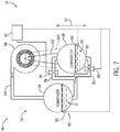
- FIG. 7 is a schematic diagram illustrating an embodiment of a free-cooling circuit 96 (e.g., a portion of the vapor compression system 14 ).
- the circuit 76 is at least part of the free-cooling circuit 96 .
- the vapor compression system 14 may utilize free-cooling to further improve an efficiency of the vapor compression system 14 .
- the free-cooling circuit 96 includes the condenser 34 fluidly coupled to the top portion 80 of the evaporator 38 via the primary conduit 78 .
- the primary conduit 78 includes the expansion valve 36 , which may adjust a flow of the refrigerant directed into the evaporator 38 via the primary conduit 78 .
- the condenser 34 has the first liquid level 90
- the evaporator 38 has the second liquid level 92
- one or both of the liquid levels 90 and 92 may be monitored by the liquid level probes 93 .
- the secondary conduit 82 is physically coupled to the bottom portion 86 of the evaporator 38 .
- the secondary conduit 82 may be physically coupled to the side portion 94 of the evaporator 38 .
- the refrigerant flowing through the secondary conduit 82 may be directed into the bottom portion 86 of the evaporator 38 .
- the secondary conduit 82 includes the valve 88 , which regulates and/or selectively enables refrigerant flow from the condenser 34 to the evaporator 38 via the secondary conduit 82 .
- the free-cooling circuit 96 also includes a compressor 98 (e.g., the compressor 32 ) fluidly coupled to the evaporator 38 via a third conduit 100 .
- the compressor 98 is configured to draw a flow 102 of refrigerant (e.g., vapor refrigerant) from the evaporator 38 and direct the flow 102 of refrigerant to the condenser 34 . While the compressor 98 is not illustrated in FIGS. 5 and 6 , it should be recognized that the circuit 76 of FIGS. 5 and 6 may also include the compressor 98 .
- the compressor 98 may be turned off or may run at a lower capacity than in normal operation (e.g., when ambient temperature is at or above the threshold value).
- the bypass line e.g., the secondary conduit 82
- the bypass line may facilitate operation of the free-cooling circuit 96 by providing a pathway for liquid refrigerant to reach the evaporator 38 without mechanical force (e.g., a pressure differential created via the compressor 98 and/or a pump).
- vapor refrigerant may flow from the evaporator 38 , through the third conduit 100 , through the compressor 98 , through a fourth conduit 104 , and into the condenser 34 via a pressure differential and/or temperature differential between the evaporator 38 and the condenser 34 .
- the vapor refrigerant then condenses to liquid and collects in the liquid collection portion 91 of the condenser 34 .
- the bypass line e.g., the secondary conduit 82
- the bypass line enables the liquid refrigerant to flow from the condenser 34 to the evaporator 38 via gravitational force (and/or pressure head from the liquid collected in the liquid collection portion 91 of the condenser 34 ).
- mechanical forces such as the compressor 98 and/or a pump, are not utilized during free cooling and power input is reduced.
- FIG. 8 is a flow chart illustrating an embodiment of a process 110 for operating the valve 36 and/or the valve 88 of the circuit 76 and/or the free-cooling circuit 96 , in accordance with aspects of the present disclosure. It is to be understood that the steps discussed herein are merely exemplary, and certain steps may be omitted or performed in a different order than the order described below. In some embodiments, the process 110 may be stored in the non-volatile memory 46 and executed by the microprocessor 44 of the control panel 40 or stored in other suitable memory and executed by other suitable processing circuitry.
- the microprocessor 44 receives feedback indicative of a pressure differential between the condenser 34 and the evaporator 38 .
- the feedback indicative of the pressure differential between the condenser 34 and the evaporator 38 may be a liquid level of refrigerant in the condenser 34 , a liquid level of refrigerant in the evaporator 38 , a liquid level of refrigerant in the primary conduit 78 , a pressure or temperature within the condenser 34 , a pressure or temperature within the evaporator 38 , an amount of power supplied to a compressor (e.g., the compressor 32 ) included in the vapor compression system 14 , a speed of the compressor (e.g., the compressor 32 ), a flow rate of refrigerant in the primary conduit 78 , a flow rate of refrigerant in another portion of the vapor compression system 14 , another suitable parameter, or any combination thereof.
- the microprocessor may be a liquid level of refrigerant in the condenser 34
- the microprocessor 44 may compare the feedback to a threshold. For example, the microprocessor 44 may determine that a liquid level of the refrigerant in the condenser 34 is above a threshold level. As such, at block 116 , the microprocessor 44 may send a control signal to actuate (e.g., partially or completely open) the valve 88 to fluidly couple the condenser 34 (and/or the primary conduit 78 ) to the evaporator 38 via the secondary conduit 82 .
- the valve 88 may be a step valve, a solenoid valve, a continuous modulating valve, or any suitable valve.
- the microprocessor 44 may regulate operation of the vapor compression system 14 based on the feedback indicative of the pressure differential between the condenser 34 and the evaporator 38 and/or another suitable operating parameter.
- the microprocessor 44 may determine a position of the expansion valve 36 before actuating the valve 88 . For example, the microprocessor 44 may determine that the expansion valve 36 is not completely open. As such, rather than the microprocessor 44 sending a control signal to open the valve 88 , the microprocessor 44 may send a control signal to continue actuating (e.g., opening or incrementally opening) the expansion valve 36 . This process may repeat until the valve 36 is in a fully open position. Once the expansion valve 36 is in the fully open position, or reaches another suitable threshold position, the microprocessor 44 may send a control signal to actuate (e.g., open) the valve 88 .
- the microprocessor 44 may send a control signal to actuate (e.g., open) the valve 88 .
- the microprocessor 44 may not send a control signal to open the valve 88 until the expansion valve 36 is completely opened or sufficiently opened (e.g., opened such that the feedback indicative of the pressure differential between the condenser 34 and the evaporator 38 is at or below a certain threshold).
- the microprocessor 44 may send a control signal to open the valve 88 before the feedback indicative of the pressure differential between the condenser 34 and the evaporator 38 reaches the threshold.
- the microprocessor 44 may send a control signal to actuate (e.g., open) the valve 88 when the feedback indicative of the pressure differential between the condenser 34 and the evaporator 38 reaches 80% of the threshold.
- the microprocessor 44 may send a control signal to actuate (e.g., close) the expansion valve 36 when the microprocessor 44 determines that the valve 88 should be opened. For example, before or after the valve 88 is actuated (e.g., adjusted toward an open position via a control signal from the microprocessor 44 ), the expansion valve 36 may be partially closed (e.g., 50%) or fully closed. The microprocessor 44 may then send a control signal to actuate (e.g., open) the valve 88 .
- the microprocessor 44 is configured to open the valve 88 incrementally based on the feedback indicative of the pressure differential between the condenser 34 and the evaporator 38 .
- the valve 88 may be a step valve having a plurality of positions between a fully open position and a fully closed position. As such, the microprocessor 44 may adjust a position of the valve 88 to incrementally increase or decrease a flow of the refrigerant through the secondary conduit 82 .
- the microprocessor 44 may receive feedback from the liquid level sensor 93 configured to monitor the liquid level 90 in the condenser 34 .
- the microprocessor 44 may receive feedback that the liquid level 90 in the condenser 34 has exceeded a threshold programmed in the non-volatile memory 46 of the control panel 40 .
- the microprocessor 44 may send a signal to the valve 88 (e.g., an actuator of the valve 88 ) to adjust the valve 88 toward an open position.
- the microprocessor 44 may determine a position of the expansion valve 36 and adjust a position of the valve 88 based on the position of the expansion valve 36 .
- the microprocessor 44 may send an additional control signal to the expansion valve 36 (e.g., an actuator of the expansion valve 36 ) to adjust the expansion valve 36 toward a closed position when the liquid level 90 in the condenser 34 exceeds the threshold.
- the microprocessor 44 may adjust the expansion valve 36 toward an open position upon opening the valve 88 in order to account for a lag time in refrigerant flow to the evaporator 38 via the secondary conduit 82 (e.g., a lag time between opening the valve 88 and a flow of refrigerant entering the evaporator 38 via the secondary conduit 82 ).
- the microprocessor 44 may modulate both the expansion valve 36 and the valve 88 based on the liquid level 90 in the condenser 34 in order to maintain the liquid level 90 at a target level. For instance, the microprocessor 44 may continuously, or substantially continuously, adjust the position of the expansion valve 36 , the valve 88 , or both, to maintain the liquid level 90 in the condenser 34 at the target level.
- the present disclosure is directed to a vapor compression system that includes a bypass line between the condenser and the evaporator.
- the bypass line may selectively fluidly couple the condenser to the evaporator via a flow path having relatively little resistance based on feedback indicative of a pressure differential between the condenser and the evaporator.
- a flow of refrigerant from the condenser to the evaporator may be facilitated because the flow path having relatively little resistance may utilize gravitational force to direct the refrigerant from the condenser to the evaporator.
- the flow path formed by the bypass line may be generally aligned in a downward direction from the condenser to the evaporator.
- the bypass line may connect to a side or a bottom portion of the evaporator. In any case, refrigerant flowing into the evaporator via the bypass line is directed toward, and accumulates in, the bottom portion of the evaporator.
Landscapes
- Engineering & Computer Science (AREA)
- Physics & Mathematics (AREA)
- Mechanical Engineering (AREA)
- Thermal Sciences (AREA)
- General Engineering & Computer Science (AREA)
- Cooling Or The Like Of Electrical Apparatus (AREA)
- Air Conditioning Control Device (AREA)
- Air-Conditioning For Vehicles (AREA)
- Compressors, Vaccum Pumps And Other Relevant Systems (AREA)
Abstract
Description
Claims (9)
Priority Applications (9)
| Application Number | Priority Date | Filing Date | Title |
|---|---|---|---|
| US16/171,145 US10697674B2 (en) | 2018-07-10 | 2018-10-25 | Bypass line for refrigerant |
| JP2021500601A JP7187659B2 (en) | 2018-07-10 | 2019-03-07 | vapor compression system |
| EP19712447.2A EP3821179B1 (en) | 2018-07-10 | 2019-03-07 | Vapor compression system |
| KR1020237032056A KR102705293B1 (en) | 2018-07-10 | 2019-03-07 | Vapor compression system |
| CN202211491863.4A CN115727555A (en) | 2018-07-10 | 2019-03-07 | vapor compression system |
| PCT/US2019/021215 WO2020013894A1 (en) | 2018-07-10 | 2019-03-07 | Vapor compression system |
| KR1020217003986A KR102581931B1 (en) | 2018-07-10 | 2019-03-07 | vapor compression system |
| CN201980055846.6A CN112639377B (en) | 2018-07-10 | 2019-03-07 | vapor compression system |
| US17/258,728 US11592212B2 (en) | 2018-07-10 | 2019-03-17 | Bypass line for refrigerant |
Applications Claiming Priority (2)
| Application Number | Priority Date | Filing Date | Title |
|---|---|---|---|
| US201862696276P | 2018-07-10 | 2018-07-10 | |
| US16/171,145 US10697674B2 (en) | 2018-07-10 | 2018-10-25 | Bypass line for refrigerant |
Related Child Applications (1)
| Application Number | Title | Priority Date | Filing Date |
|---|---|---|---|
| US17/258,728 Continuation US11592212B2 (en) | 2018-07-10 | 2019-03-17 | Bypass line for refrigerant |
Publications (2)
| Publication Number | Publication Date |
|---|---|
| US20200018529A1 US20200018529A1 (en) | 2020-01-16 |
| US10697674B2 true US10697674B2 (en) | 2020-06-30 |
Family
ID=69138720
Family Applications (2)
| Application Number | Title | Priority Date | Filing Date |
|---|---|---|---|
| US16/171,145 Active US10697674B2 (en) | 2018-07-10 | 2018-10-25 | Bypass line for refrigerant |
| US17/258,728 Active 2038-12-10 US11592212B2 (en) | 2018-07-10 | 2019-03-17 | Bypass line for refrigerant |
Family Applications After (1)
| Application Number | Title | Priority Date | Filing Date |
|---|---|---|---|
| US17/258,728 Active 2038-12-10 US11592212B2 (en) | 2018-07-10 | 2019-03-17 | Bypass line for refrigerant |
Country Status (6)
| Country | Link |
|---|---|
| US (2) | US10697674B2 (en) |
| EP (1) | EP3821179B1 (en) |
| JP (1) | JP7187659B2 (en) |
| KR (2) | KR102581931B1 (en) |
| CN (2) | CN112639377B (en) |
| WO (1) | WO2020013894A1 (en) |
Cited By (1)
| Publication number | Priority date | Publication date | Assignee | Title |
|---|---|---|---|---|
| US12429257B2 (en) | 2020-09-30 | 2025-09-30 | Tyco Fire & Security Gmbh | HVAC system with bypass conduit |
Families Citing this family (2)
| Publication number | Priority date | Publication date | Assignee | Title |
|---|---|---|---|---|
| US11079150B2 (en) * | 2018-02-20 | 2021-08-03 | Blue Star Limited | Method for controlling level of liquid within an evaporator and a system thereof |
| US11828508B2 (en) * | 2021-03-29 | 2023-11-28 | LGL France S.A.S. | Combined chiller and free cooling system for operation at high ambient temperature |
Citations (54)
| Publication number | Priority date | Publication date | Assignee | Title |
|---|---|---|---|---|
| US3141311A (en) | 1963-01-14 | 1964-07-21 | Carrier Corp | Refrigeration system and apparatus for operating at partial loads |
| US3161029A (en) | 1962-10-04 | 1964-12-15 | Carrier Corp | Refrigeration systems operable at low condenser pressures |
| US3191396A (en) * | 1963-01-14 | 1965-06-29 | Carrier Corp | Refrigeration system and apparatus for operation at low loads |
| US3210955A (en) | 1963-07-22 | 1965-10-12 | Carrier Corp | Refrigeration apparatus |
| US3238737A (en) * | 1964-03-31 | 1966-03-08 | Larkin Coils Inc | Heated receiver winter control for refrigeration systems |
| US3242689A (en) | 1964-03-13 | 1966-03-29 | Worthington Corp | Cooling system and apparatus |
| US3496992A (en) * | 1961-05-25 | 1970-02-24 | Carrier Corp | Method and apparatus for heating and cooling |
| US3680324A (en) * | 1970-12-07 | 1972-08-01 | Frick Co | Vaporator refrigerant feed modulated from a variable load |
| US3791160A (en) | 1971-09-16 | 1974-02-12 | Nat Union Electric Corp | Air conditioning system with temperature responsive controls |
| US4019337A (en) * | 1974-10-23 | 1977-04-26 | Zearfoss Jr Elmer W | Refrigeration apparatus and method |
| US4171623A (en) * | 1977-08-29 | 1979-10-23 | Carrier Corporation | Thermal economizer application for a centrifugal refrigeration machine |
| US4332136A (en) * | 1980-04-29 | 1982-06-01 | Sulzer Brothers Ltd. | Refrigerating apparatus |
| US4550574A (en) | 1983-06-02 | 1985-11-05 | Sexton-Espec, Inc. | Refrigeration system with liquid bypass line |
| US4832068A (en) | 1987-12-21 | 1989-05-23 | American Standard Inc. | Liquid/gas bypass |
| US5117645A (en) * | 1990-05-23 | 1992-06-02 | Inter-City Products Corporation (Usa) | Refrigeration system with saturation sensor |
| US5159972A (en) | 1991-03-21 | 1992-11-03 | Florida Power Corporation | Controllable heat pipes for thermal energy transfer |
| US5319945A (en) * | 1992-06-29 | 1994-06-14 | American Standard Inc. | Method and apparatus for non-atmospheric venting of evaporator over-pressure in a refrigeration system |
| US5351500A (en) * | 1993-12-03 | 1994-10-04 | Texas Medical Center Central Heating And Cooling Cooperative Association | Refrigerant leak detector system |
| US5539382A (en) * | 1995-04-21 | 1996-07-23 | Carrier Corporation | System for monitoring the operation of a condenser unit |
| US5542261A (en) * | 1995-04-17 | 1996-08-06 | Albertson; Luther D. | Refrigerant evaporator over-pressure relief system including a fluid containment vessel |
| US5546073A (en) * | 1995-04-21 | 1996-08-13 | Carrier Corporation | System for monitoring the operation of a compressor unit |
| US5638691A (en) * | 1995-05-25 | 1997-06-17 | American Standard Inc. | Falling film evaporator with refrigerant distribution system |
| US5677677A (en) * | 1995-04-21 | 1997-10-14 | Carrier Corporation | System for monitoring the operation of an evaporator unit |
| US5826433A (en) * | 1997-03-25 | 1998-10-27 | Dube; Serge | Refrigeration system with heat reclaim and efficiency control modulating valve |
| US6167713B1 (en) | 1999-03-12 | 2001-01-02 | American Standard Inc. | Falling film evaporator having two-phase distribution system |
| US6253562B1 (en) * | 1999-12-27 | 2001-07-03 | Carrier Corporation | Refrigerant subcooler for vapor compression refrigeration system |
| US6293112B1 (en) | 1999-12-17 | 2001-09-25 | American Standard International Inc. | Falling film evaporator for a vapor compression refrigeration chiller |
| US6382310B1 (en) * | 2000-08-15 | 2002-05-07 | American Standard International Inc. | Stepped heat exchanger coils |
| US6606882B1 (en) | 2002-10-23 | 2003-08-19 | Carrier Corporation | Falling film evaporator with a two-phase flow distributor |
| US20090178790A1 (en) * | 2008-01-11 | 2009-07-16 | Johnson Controls Technology Company | Vapor compression system |
| WO2009135297A1 (en) | 2008-05-08 | 2009-11-12 | Unified Corporation | Multiple mode refrigeration |
| JP2010230264A (en) | 2009-03-27 | 2010-10-14 | Sanki Eng Co Ltd | Steam compression refrigerator system |
| US20140102665A1 (en) * | 2012-10-16 | 2014-04-17 | Trane International Inc. | Fluid management in a hvac system |
| US20150345846A1 (en) * | 2013-01-15 | 2015-12-03 | Johnson Controls Technology Company | Air cooled chiller with heat recovery |
| US20160003508A1 (en) | 2013-02-19 | 2016-01-07 | Carrier Corporation | Evaporator distribution system and method |
| US9291409B1 (en) * | 2013-03-15 | 2016-03-22 | Rodney T. Heath | Compressor inter-stage temperature control |
| US20160187011A1 (en) * | 2014-11-21 | 2016-06-30 | 7Ac Technologies, Inc. | Methods and systems for mini-split liquid desiccant air conditioning |
| US9459032B2 (en) | 2008-02-29 | 2016-10-04 | Daikin Industries, Ltd. | Air conditioning apparatus and refrigerant quantity determination method |
| EP3087331A1 (en) | 2013-12-24 | 2016-11-02 | Carrier Corporation | Refrigerant riser for evaporator |
| EP3091312A1 (en) | 2013-12-30 | 2016-11-09 | Mcquay Air-conditioning & Refrigeration (Wuhan) Co. | Falling film evaporator |
| US20160341457A1 (en) | 2014-01-15 | 2016-11-24 | Carrier Corporation | Refrigerant distributor for falling film evaporator |
| US20170038110A1 (en) * | 2014-04-16 | 2017-02-09 | Johnson Controls Technology Company | Method for operating a chiller |
| US20170211868A1 (en) * | 2016-01-27 | 2017-07-27 | General Electric Company | Microchannel Condenser and Dual Evaporator Refrigeration System |
| US20170254568A1 (en) * | 2014-09-05 | 2017-09-07 | Mitsubishi Heavy Industries, Ltd. | Centrifugal chiller |
| EP3247948A2 (en) | 2015-01-08 | 2017-11-29 | Bry-Air (Asia) Pvt. Ltd. | Split level sorption refrigeration system |
| US20180010833A1 (en) * | 2016-07-07 | 2018-01-11 | Trane International Inc. | Accumulator for charge management |
| US9915451B2 (en) | 2013-02-19 | 2018-03-13 | Carrier Corporation | Level control in an evaporator |
| US9915436B1 (en) * | 2015-01-20 | 2018-03-13 | Ralph Feria | Heat source optimization system |
| US20180187931A1 (en) * | 2015-01-20 | 2018-07-05 | Ralph Feria | Heat Source Optimization System |
| US20180231280A1 (en) * | 2017-02-13 | 2018-08-16 | Daikin Applied Americas Inc. | Condenser with tube support structure |
| US20190011152A1 (en) * | 2016-03-14 | 2019-01-10 | Efficient Energy Gmbh | Heat pump system comprising two stages, method of operating a heat pump system and method of producing a heat pump system |
| WO2019023267A1 (en) | 2017-07-24 | 2019-01-31 | Johnson Controls Technology Company | Refrigerant composition measurement system |
| US20190368786A1 (en) * | 2018-06-05 | 2019-12-05 | Hill Phoenix, Inc. | Co2 refrigeration system with magnetic refrigeration system cooling |
| US20190383536A1 (en) * | 2018-06-15 | 2019-12-19 | Johnson Controls Technology Company | Adjustable duct for hvac system |
Family Cites Families (15)
| Publication number | Priority date | Publication date | Assignee | Title |
|---|---|---|---|---|
| US2986894A (en) * | 1958-02-03 | 1961-06-06 | Carrier Corp | Purge recovery arrangement for refrigeration systems |
| US3013404A (en) * | 1960-01-04 | 1961-12-19 | Carrier Corp | Purge mechanism for refrigeration system |
| US3158009A (en) * | 1963-01-23 | 1964-11-24 | Worthington Corp | Refrigeration apparatus including compressor motor cooling means |
| US3241331A (en) * | 1963-04-17 | 1966-03-22 | Carrier Corp | Apparatus for and method of motor cooling |
| US3270521A (en) * | 1965-09-08 | 1966-09-06 | Worthington Corp | Refrigerant cooled oil cooler system |
| US3299653A (en) * | 1965-10-20 | 1967-01-24 | Carrier Corp | Refrigeration system |
| US3744273A (en) * | 1972-03-27 | 1973-07-10 | Trane Co | Refrigeration apparatus and method of operating for powered and nonpowered cooling modes |
| JP3307915B2 (en) * | 1995-08-31 | 2002-07-29 | 三菱電機株式会社 | Cooling device |
| US5839294A (en) * | 1996-11-19 | 1998-11-24 | Carrier Corporation | Chiller with hybrid falling film evaporator |
| WO2006083329A2 (en) * | 2005-02-02 | 2006-08-10 | Carrier Corporation | Refrigerating system with economizing cycle |
| JP5752428B2 (en) * | 2011-01-17 | 2015-07-22 | 新日本空調株式会社 | Water refrigerant refrigeration system |
| CN203395990U (en) * | 2013-08-12 | 2014-01-15 | 北京雅驿欣科技有限公司 | Spray cooling and energy-saving function integrated multi-refrigeration-cycle air conditioning unit |
| CN203572086U (en) * | 2013-10-17 | 2014-04-30 | 南京天加空调设备有限公司 | Falling film type screw water chilling unit for achieving variable temperature difference through variable procedure |
| CN105241104A (en) * | 2014-05-29 | 2016-01-13 | 重庆美的通用制冷设备有限公司 | Refrigeration system and air conditioner |
| CN107131687B (en) * | 2016-02-29 | 2023-07-11 | 约克(无锡)空调冷冻设备有限公司 | A heat exchange device suitable for low-pressure refrigerant |
-
2018
- 2018-10-25 US US16/171,145 patent/US10697674B2/en active Active
-
2019
- 2019-03-07 KR KR1020217003986A patent/KR102581931B1/en active Active
- 2019-03-07 CN CN201980055846.6A patent/CN112639377B/en active Active
- 2019-03-07 KR KR1020237032056A patent/KR102705293B1/en active Active
- 2019-03-07 EP EP19712447.2A patent/EP3821179B1/en active Active
- 2019-03-07 WO PCT/US2019/021215 patent/WO2020013894A1/en not_active Ceased
- 2019-03-07 CN CN202211491863.4A patent/CN115727555A/en active Pending
- 2019-03-07 JP JP2021500601A patent/JP7187659B2/en active Active
- 2019-03-17 US US17/258,728 patent/US11592212B2/en active Active
Patent Citations (55)
| Publication number | Priority date | Publication date | Assignee | Title |
|---|---|---|---|---|
| US3496992A (en) * | 1961-05-25 | 1970-02-24 | Carrier Corp | Method and apparatus for heating and cooling |
| US3161029A (en) | 1962-10-04 | 1964-12-15 | Carrier Corp | Refrigeration systems operable at low condenser pressures |
| US3141311A (en) | 1963-01-14 | 1964-07-21 | Carrier Corp | Refrigeration system and apparatus for operating at partial loads |
| US3191396A (en) * | 1963-01-14 | 1965-06-29 | Carrier Corp | Refrigeration system and apparatus for operation at low loads |
| US3210955A (en) | 1963-07-22 | 1965-10-12 | Carrier Corp | Refrigeration apparatus |
| US3242689A (en) | 1964-03-13 | 1966-03-29 | Worthington Corp | Cooling system and apparatus |
| US3238737A (en) * | 1964-03-31 | 1966-03-08 | Larkin Coils Inc | Heated receiver winter control for refrigeration systems |
| US3680324A (en) * | 1970-12-07 | 1972-08-01 | Frick Co | Vaporator refrigerant feed modulated from a variable load |
| US3791160A (en) | 1971-09-16 | 1974-02-12 | Nat Union Electric Corp | Air conditioning system with temperature responsive controls |
| US4019337A (en) * | 1974-10-23 | 1977-04-26 | Zearfoss Jr Elmer W | Refrigeration apparatus and method |
| US4171623A (en) * | 1977-08-29 | 1979-10-23 | Carrier Corporation | Thermal economizer application for a centrifugal refrigeration machine |
| US4332136A (en) * | 1980-04-29 | 1982-06-01 | Sulzer Brothers Ltd. | Refrigerating apparatus |
| US4550574A (en) | 1983-06-02 | 1985-11-05 | Sexton-Espec, Inc. | Refrigeration system with liquid bypass line |
| US4832068A (en) | 1987-12-21 | 1989-05-23 | American Standard Inc. | Liquid/gas bypass |
| US5117645A (en) * | 1990-05-23 | 1992-06-02 | Inter-City Products Corporation (Usa) | Refrigeration system with saturation sensor |
| US5159972A (en) | 1991-03-21 | 1992-11-03 | Florida Power Corporation | Controllable heat pipes for thermal energy transfer |
| US5319945A (en) * | 1992-06-29 | 1994-06-14 | American Standard Inc. | Method and apparatus for non-atmospheric venting of evaporator over-pressure in a refrigeration system |
| US5351500A (en) * | 1993-12-03 | 1994-10-04 | Texas Medical Center Central Heating And Cooling Cooperative Association | Refrigerant leak detector system |
| US5542261A (en) * | 1995-04-17 | 1996-08-06 | Albertson; Luther D. | Refrigerant evaporator over-pressure relief system including a fluid containment vessel |
| US5539382A (en) * | 1995-04-21 | 1996-07-23 | Carrier Corporation | System for monitoring the operation of a condenser unit |
| US5546073A (en) * | 1995-04-21 | 1996-08-13 | Carrier Corporation | System for monitoring the operation of a compressor unit |
| US5677677A (en) * | 1995-04-21 | 1997-10-14 | Carrier Corporation | System for monitoring the operation of an evaporator unit |
| US5638691A (en) * | 1995-05-25 | 1997-06-17 | American Standard Inc. | Falling film evaporator with refrigerant distribution system |
| US5826433A (en) * | 1997-03-25 | 1998-10-27 | Dube; Serge | Refrigeration system with heat reclaim and efficiency control modulating valve |
| US6167713B1 (en) | 1999-03-12 | 2001-01-02 | American Standard Inc. | Falling film evaporator having two-phase distribution system |
| US6293112B1 (en) | 1999-12-17 | 2001-09-25 | American Standard International Inc. | Falling film evaporator for a vapor compression refrigeration chiller |
| US6253562B1 (en) * | 1999-12-27 | 2001-07-03 | Carrier Corporation | Refrigerant subcooler for vapor compression refrigeration system |
| US6382310B1 (en) * | 2000-08-15 | 2002-05-07 | American Standard International Inc. | Stepped heat exchanger coils |
| US6606882B1 (en) | 2002-10-23 | 2003-08-19 | Carrier Corporation | Falling film evaporator with a two-phase flow distributor |
| US20090178790A1 (en) * | 2008-01-11 | 2009-07-16 | Johnson Controls Technology Company | Vapor compression system |
| US9459032B2 (en) | 2008-02-29 | 2016-10-04 | Daikin Industries, Ltd. | Air conditioning apparatus and refrigerant quantity determination method |
| WO2009135297A1 (en) | 2008-05-08 | 2009-11-12 | Unified Corporation | Multiple mode refrigeration |
| JP2010230264A (en) | 2009-03-27 | 2010-10-14 | Sanki Eng Co Ltd | Steam compression refrigerator system |
| US20140102665A1 (en) * | 2012-10-16 | 2014-04-17 | Trane International Inc. | Fluid management in a hvac system |
| US9523523B2 (en) | 2012-10-16 | 2016-12-20 | Trane International Inc. | System and method for managing fluid level in a HVAC system |
| US20150345846A1 (en) * | 2013-01-15 | 2015-12-03 | Johnson Controls Technology Company | Air cooled chiller with heat recovery |
| US20160003508A1 (en) | 2013-02-19 | 2016-01-07 | Carrier Corporation | Evaporator distribution system and method |
| US9915451B2 (en) | 2013-02-19 | 2018-03-13 | Carrier Corporation | Level control in an evaporator |
| US9291409B1 (en) * | 2013-03-15 | 2016-03-22 | Rodney T. Heath | Compressor inter-stage temperature control |
| EP3087331A1 (en) | 2013-12-24 | 2016-11-02 | Carrier Corporation | Refrigerant riser for evaporator |
| EP3091312A1 (en) | 2013-12-30 | 2016-11-09 | Mcquay Air-conditioning & Refrigeration (Wuhan) Co. | Falling film evaporator |
| US20160341457A1 (en) | 2014-01-15 | 2016-11-24 | Carrier Corporation | Refrigerant distributor for falling film evaporator |
| US20170038110A1 (en) * | 2014-04-16 | 2017-02-09 | Johnson Controls Technology Company | Method for operating a chiller |
| US20170254568A1 (en) * | 2014-09-05 | 2017-09-07 | Mitsubishi Heavy Industries, Ltd. | Centrifugal chiller |
| US20160187011A1 (en) * | 2014-11-21 | 2016-06-30 | 7Ac Technologies, Inc. | Methods and systems for mini-split liquid desiccant air conditioning |
| EP3247948A2 (en) | 2015-01-08 | 2017-11-29 | Bry-Air (Asia) Pvt. Ltd. | Split level sorption refrigeration system |
| US9915436B1 (en) * | 2015-01-20 | 2018-03-13 | Ralph Feria | Heat source optimization system |
| US20180187931A1 (en) * | 2015-01-20 | 2018-07-05 | Ralph Feria | Heat Source Optimization System |
| US20170211868A1 (en) * | 2016-01-27 | 2017-07-27 | General Electric Company | Microchannel Condenser and Dual Evaporator Refrigeration System |
| US20190011152A1 (en) * | 2016-03-14 | 2019-01-10 | Efficient Energy Gmbh | Heat pump system comprising two stages, method of operating a heat pump system and method of producing a heat pump system |
| US20180010833A1 (en) * | 2016-07-07 | 2018-01-11 | Trane International Inc. | Accumulator for charge management |
| US20180231280A1 (en) * | 2017-02-13 | 2018-08-16 | Daikin Applied Americas Inc. | Condenser with tube support structure |
| WO2019023267A1 (en) | 2017-07-24 | 2019-01-31 | Johnson Controls Technology Company | Refrigerant composition measurement system |
| US20190368786A1 (en) * | 2018-06-05 | 2019-12-05 | Hill Phoenix, Inc. | Co2 refrigeration system with magnetic refrigeration system cooling |
| US20190383536A1 (en) * | 2018-06-15 | 2019-12-19 | Johnson Controls Technology Company | Adjustable duct for hvac system |
Non-Patent Citations (3)
| Title |
|---|
| Armstrong, et al., Efficient Low-Lift Cooling with Radiant Distribution, Thermal Storage and Variable-Speed Chiller Controls Part I: Component and Subsystem Models, HVAC&R Research, Mar. 2009, vol. 15, No. 2, American Society of Heating, Refrigerating and Air-Conditioning Engineers, Inc., 36 pgs. |
| Evaporator and Condenser, http://lekmin.club/evaporator-and-condenser/, accessed on Oct. 25, 2018. |
| PCT International Search Report and Written Opinion; PCT Application No. PCT/US2019/021215; dated Jun. 3, 2019. |
Cited By (1)
| Publication number | Priority date | Publication date | Assignee | Title |
|---|---|---|---|---|
| US12429257B2 (en) | 2020-09-30 | 2025-09-30 | Tyco Fire & Security Gmbh | HVAC system with bypass conduit |
Also Published As
| Publication number | Publication date |
|---|---|
| KR102705293B1 (en) | 2024-09-11 |
| US20200018529A1 (en) | 2020-01-16 |
| CN112639377A (en) | 2021-04-09 |
| KR102581931B1 (en) | 2023-09-22 |
| US20210156602A1 (en) | 2021-05-27 |
| EP3821179B1 (en) | 2023-05-03 |
| KR20230137494A (en) | 2023-10-04 |
| EP3821179A1 (en) | 2021-05-19 |
| JP7187659B2 (en) | 2022-12-12 |
| WO2020013894A1 (en) | 2020-01-16 |
| CN112639377B (en) | 2022-12-02 |
| KR20210030428A (en) | 2021-03-17 |
| US11592212B2 (en) | 2023-02-28 |
| JP2021530664A (en) | 2021-11-11 |
| CN115727555A (en) | 2023-03-03 |
Similar Documents
| Publication | Publication Date | Title |
|---|---|---|
| US11378314B2 (en) | Air cooled chiller with heat recovery | |
| CN106574812B (en) | Outdoor unit and refrigerating circulatory device | |
| US20170191718A1 (en) | Vapor compression system | |
| CN105180513A (en) | Heat Pump System With Multiple Operating Modes | |
| US10443910B2 (en) | Air conditioning apparatus | |
| US11592212B2 (en) | Bypass line for refrigerant | |
| US11976857B2 (en) | Refrigeration cycle device | |
| US20260029176A1 (en) | Hvac system with bypass conduit | |
| US20230080007A1 (en) | Free cooling system for hvac system | |
| US20230324093A1 (en) | Expansion valve control system | |
| WO2023239872A1 (en) | Systems and methods for controlling a chiller | |
| US20250383156A1 (en) | Microchannel heat exchanger with varying fin density | |
| CN120092160A (en) | Heating, ventilation, air conditioning and/or refrigeration systems with heating and cooling operations |
Legal Events
| Date | Code | Title | Description |
|---|---|---|---|
| FEPP | Fee payment procedure |
Free format text: ENTITY STATUS SET TO UNDISCOUNTED (ORIGINAL EVENT CODE: BIG.); ENTITY STATUS OF PATENT OWNER: LARGE ENTITY |
|
| AS | Assignment |
Owner name: JOHNSON CONTROLS TECHNOLOGY COMPANY, MICHIGAN Free format text: ASSIGNMENT OF ASSIGNORS INTEREST;ASSIGNORS:SCHREIBER, JEB WILLIAM;GLADFELTER, SETH KEVIN;KREBS, KEVIN DONALD;SIGNING DATES FROM 20181015 TO 20181024;REEL/FRAME:047671/0539 |
|
| STPP | Information on status: patent application and granting procedure in general |
Free format text: FINAL REJECTION MAILED |
|
| STPP | Information on status: patent application and granting procedure in general |
Free format text: NOTICE OF ALLOWANCE MAILED -- APPLICATION RECEIVED IN OFFICE OF PUBLICATIONS |
|
| AS | Assignment |
Owner name: JOHNSON CONTROLS TECHNOLOGY COMPANY, MICHIGAN Free format text: ASSIGNMENT OF ASSIGNORS INTEREST;ASSIGNOR:NELSON, CAMERON STUART;REEL/FRAME:052728/0961 Effective date: 20190730 |
|
| STCF | Information on status: patent grant |
Free format text: PATENTED CASE |
|
| AS | Assignment |
Owner name: JOHNSON CONTROLS TYCO IP HOLDINGS LLP, WISCONSIN Free format text: NUNC PRO TUNC ASSIGNMENT;ASSIGNOR:JOHNSON CONTROLS TECHNOLOGY COMPANY;REEL/FRAME:058959/0764 Effective date: 20210806 |
|
| MAFP | Maintenance fee payment |
Free format text: PAYMENT OF MAINTENANCE FEE, 4TH YEAR, LARGE ENTITY (ORIGINAL EVENT CODE: M1551); ENTITY STATUS OF PATENT OWNER: LARGE ENTITY Year of fee payment: 4 |
|
| AS | Assignment |
Owner name: TYCO FIRE & SECURITY GMBH, SWITZERLAND Free format text: ASSIGNMENT OF ASSIGNORS INTEREST;ASSIGNOR:JOHNSON CONTROLS TYCO IP HOLDINGS LLP;REEL/FRAME:072290/0853 Effective date: 20240201 |