EP3219983A1 - Véhicule de transport de pale - Google Patents
Véhicule de transport de pale Download PDFInfo
- Publication number
- EP3219983A1 EP3219983A1 EP17157041.9A EP17157041A EP3219983A1 EP 3219983 A1 EP3219983 A1 EP 3219983A1 EP 17157041 A EP17157041 A EP 17157041A EP 3219983 A1 EP3219983 A1 EP 3219983A1
- Authority
- EP
- European Patent Office
- Prior art keywords
- blade
- disposed
- plate
- base
- transport vehicle
- Prior art date
- Legal status (The legal status is an assumption and is not a legal conclusion. Google has not performed a legal analysis and makes no representation as to the accuracy of the status listed.)
- Granted
Links
- 230000032258 transport Effects 0.000 description 155
- 238000005259 measurement Methods 0.000 description 38
- 238000005096 rolling process Methods 0.000 description 38
- 238000006243 chemical reaction Methods 0.000 description 37
- 230000001133 acceleration Effects 0.000 description 36
- 229910000831 Steel Inorganic materials 0.000 description 34
- 239000010959 steel Substances 0.000 description 34
- 239000000463 material Substances 0.000 description 29
- 238000005299 abrasion Methods 0.000 description 15
- 230000008859 change Effects 0.000 description 14
- 238000003466 welding Methods 0.000 description 13
- 230000002093 peripheral effect Effects 0.000 description 12
- 230000035939 shock Effects 0.000 description 11
- 230000007423 decrease Effects 0.000 description 9
- 230000005484 gravity Effects 0.000 description 9
- 206010016256 fatigue Diseases 0.000 description 8
- 230000003993 interaction Effects 0.000 description 4
- 238000010586 diagram Methods 0.000 description 3
- 238000010248 power generation Methods 0.000 description 3
- 230000004044 response Effects 0.000 description 3
- 230000008878 coupling Effects 0.000 description 2
- 238000010168 coupling process Methods 0.000 description 2
- 238000005859 coupling reaction Methods 0.000 description 2
- 238000000034 method Methods 0.000 description 2
- 230000006866 deterioration Effects 0.000 description 1
- 230000000694 effects Effects 0.000 description 1
- 230000002708 enhancing effect Effects 0.000 description 1
- 230000007613 environmental effect Effects 0.000 description 1
- 230000005283 ground state Effects 0.000 description 1
- 238000009434 installation Methods 0.000 description 1
- 230000004048 modification Effects 0.000 description 1
- 238000012986 modification Methods 0.000 description 1
Images


Classifications
-
- F—MECHANICAL ENGINEERING; LIGHTING; HEATING; WEAPONS; BLASTING
- F03—MACHINES OR ENGINES FOR LIQUIDS; WIND, SPRING, OR WEIGHT MOTORS; PRODUCING MECHANICAL POWER OR A REACTIVE PROPULSIVE THRUST, NOT OTHERWISE PROVIDED FOR
- F03D—WIND MOTORS
- F03D13/00—Assembly, mounting or commissioning of wind motors; Arrangements specially adapted for transporting wind motor components
- F03D13/40—Arrangements or methods specially adapted for transporting wind motor components
-
- B—PERFORMING OPERATIONS; TRANSPORTING
- B60—VEHICLES IN GENERAL
- B60P—VEHICLES ADAPTED FOR LOAD TRANSPORTATION OR TO TRANSPORT, TO CARRY, OR TO COMPRISE SPECIAL LOADS OR OBJECTS
- B60P3/00—Vehicles adapted to transport, to carry or to comprise special loads or objects
- B60P3/40—Vehicles adapted to transport, to carry or to comprise special loads or objects for carrying long loads, e.g. with separate wheeled load supporting elements
-
- B—PERFORMING OPERATIONS; TRANSPORTING
- B60—VEHICLES IN GENERAL
- B60P—VEHICLES ADAPTED FOR LOAD TRANSPORTATION OR TO TRANSPORT, TO CARRY, OR TO COMPRISE SPECIAL LOADS OR OBJECTS
- B60P7/00—Securing or covering of load on vehicles
- B60P7/06—Securing of load
- B60P7/08—Securing to the vehicle floor or sides
- B60P7/12—Securing to the vehicle floor or sides the load being tree-trunks, beams, drums, tubes, or the like
-
- B—PERFORMING OPERATIONS; TRANSPORTING
- B61—RAILWAYS
- B61D—BODY DETAILS OR KINDS OF RAILWAY VEHICLES
- B61D3/00—Wagons or vans
- B61D3/16—Wagons or vans adapted for carrying special loads
-
- B—PERFORMING OPERATIONS; TRANSPORTING
- B61—RAILWAYS
- B61D—BODY DETAILS OR KINDS OF RAILWAY VEHICLES
- B61D3/00—Wagons or vans
- B61D3/16—Wagons or vans adapted for carrying special loads
- B61D3/166—Wagons or vans adapted for carrying special loads for carrying very heavy loads
-
- B—PERFORMING OPERATIONS; TRANSPORTING
- B61—RAILWAYS
- B61D—BODY DETAILS OR KINDS OF RAILWAY VEHICLES
- B61D45/00—Means or devices for securing or supporting the cargo, including protection against shocks
- B61D45/001—Devices for fixing to walls or floors
- B61D45/003—Fixing of logs, beams, barrels, pipes, or the like
-
- B—PERFORMING OPERATIONS; TRANSPORTING
- B62—LAND VEHICLES FOR TRAVELLING OTHERWISE THAN ON RAILS
- B62D—MOTOR VEHICLES; TRAILERS
- B62D33/00—Superstructures for load-carrying vehicles
- B62D33/02—Platforms; Open load compartments
- B62D33/0207—Connections of movable or detachable racks or stanchions to platforms
-
- Y—GENERAL TAGGING OF NEW TECHNOLOGICAL DEVELOPMENTS; GENERAL TAGGING OF CROSS-SECTIONAL TECHNOLOGIES SPANNING OVER SEVERAL SECTIONS OF THE IPC; TECHNICAL SUBJECTS COVERED BY FORMER USPC CROSS-REFERENCE ART COLLECTIONS [XRACs] AND DIGESTS
- Y02—TECHNOLOGIES OR APPLICATIONS FOR MITIGATION OR ADAPTATION AGAINST CLIMATE CHANGE
- Y02E—REDUCTION OF GREENHOUSE GAS [GHG] EMISSIONS, RELATED TO ENERGY GENERATION, TRANSMISSION OR DISTRIBUTION
- Y02E10/00—Energy generation through renewable energy sources
- Y02E10/70—Wind energy
- Y02E10/72—Wind turbines with rotation axis in wind direction
Definitions
- Exemplary embodiments of the present invention relate to a blade transport vehicle.
- Wind power equipment such as a wind turbine is an eco-friendly power generation facility which converts rotational energy by wind into electric energy, and is provided as a part of renewable energy projects that have been in the spotlight in these days in which the need for global environmental protection is magnified.
- the wind power equipment may be largely classified into a nacelle and a tower.
- the nacelle is configured such that a plurality of blades rotated by wind is mounted circumferentially at predetermined intervals to a hub and a drive shaft of a rotor is connected to the center of the hub.
- rotational energy is transferred to the rotor.
- a generator connected to the rotor is built in the nacelle. The generator converts rotational energy into electric energy according to the rotation of the rotor.
- the blades play a large role in the wind power generation.
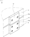
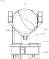
- a blade transport vehicle is used as illustrated in Fig. 1 .
- a conventional blade transport vehicle mainly includes a lower trailer 8, a hydraulic cylinder 3, a fixed frame 4, a slewing bearing unit 5, and a blade adapter 6.
- the lower trailer 8 is configured such that a plurality of wheels is arranged in multiple rows in a main body.
- the lower trailer 8 serves to distribute the load of each blade 7 and stably transport the blade 7.
- Support beams 2 are disposed at both sides of the lower trailer 8.
- the support beams 2 are extended to both sides of the lower trailer 8 in the width direction thereof by a hydraulic device and come into contact with the ground in order to move the blade 7 after the transport vehicle is stopped, thereby serving to support the load applied to the transport vehicle due to the load of the blade 7.
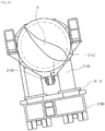
- the support beams 2 are separated from the ground by the hydraulic device while the transport vehicle is traveling.
- the fixed frame 4 is disposed at the upper end of the lower trailer 8.
- the fixed frame 4 has a pair of columns disposed at the upper end of the lower trailer 8, and the hydraulic cylinder 3 is connected by a hinge between the columns.
- the end of the rod of the hydraulic cylinder 3 is connected by a hinge to the lower end of a bearing block 5b of the slewing bearing unit 5.
- Fig. 1 illustrates the state in which the angle of the blade 7 is adjusted by the operation of the hydraulic cylinder 3 when compared to Fig. 2 .
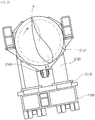
- the slewing bearing 5a is rotatably mounted to the bearing block 5b by a turning drive 5c disposed on the bearing block 5b.
- a turning drive 5c disposed on the bearing block 5b.
- the blade adapter 6 bolted to the slewing bearing 5a rotates along with the rotation of the slewing bearing 5a engaged with the turning drive 5c, thereby adjusting the angle of rotation of the blade 7.
- the conventional blade transport vehicle may not respond properly to such a situation since the user merely adjusts the vertical angle of the blade 7 using the hydraulic cylinder 3.
- unexpected incidents may occur when the blade transport vehicle 1 travels.
- the vehicle When the vehicle transports the large blade 7 having a weight of several tens of tons, the vehicle may not smoothly travel or overturn in special cases due to the motion and load of the blade 7 by the state of the ground or the effect of wind.
- the blade 7 used for wind power generation has a curved cross section. Accordingly, it is possible to obtain power by rotating the rotor while the blade rotates in one direction by wind.
- the blade 7 due to the shape of the blade, when wind is blown to the blade 7 while the vehicle travels on the road, the blade 7 is greatly affected by the direction of wind depending on the arrangement of the blade 7 toward the wind, and thus the vehicle shakes. Hence, the vehicle may lean in the direction opposite to the wind.
- the rolling of the blade 7 may be caused by wind having strong velocity, which may lead to deterioration of coupling force with the blade adapter 6 or the abrasion and damage of the blade adapter 6.
- the center of gravity of the vehicle may not be unbalanced depending on the arrangement of the blade 7 even when the vehicle travels on the slope. For this reason, since a large load is applied to the specific wheel of the lower trailer 8 by the excessive weight of the blade while the vehicle is traveling, the vehicle may also overturn.
- the blade transport vehicle 1 when the blade transport vehicle 1 travels in a sharp curve section or on a slope or passes through a tunnel or a pedestrian overpass, the blade transport vehicle may restrictively turn due to the length of the blade 7.
- the large blade 7 has a length of several tens of meters. If the curve section is very sharp, there is a risk that the large blade 7 collides with terrain features such as trees and street lights around the road since the large blade 7 is too long.
- the vehicle may be damaged due to a collision between the end of the blade and the wall of the tunnel. Accordingly, it is required to obtain the width of turning of the blade 7.
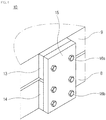
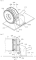
- a base 9 for supporting the fixed frame 4 must be stably fixed to the lower trailer 8 in order to stably perform the transportation and attachment/detachment of the blade.
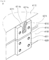
- the fixing method is performed by fastening a plurality of upper brackets 13 arranged along the side of the upper base 9 in the longitudinal direction of the vehicle and a plurality of lower brackets 14 arranged along the side of the lower trailer 8 in the longitudinal direction of the vehicle to a connection plate 15 through thread holes 13a and 14a using bolts 16a and 16b.
- the upper and lower brackets 13 and 14 each have a simple plate shape and are simply bolted to the connection plate 15 having a rectangular shape.
- the risk of fatigue failure may be increased due to the exposure of the bolts to vibration and shocks for a long time and the base 9 may not be securely fixed.
- the blade may be decoupled from the vehicle.
- Patent Document 1 Korean Patent No. 10-1564849
- the present invention has been made in view of the above-mentioned problem, and an object thereof is to provide an apparatus relating to a transport vehicle, which is capable of stably fixing a blade on a transport vehicle by changing the position of the blade in all directions on a slope.
- Another object of the present invention is to provide an apparatus capable of preventing a vehicle from overturning by adjusting an angle of arrangement of a blade and balancing a load applied to the vehicle.
- Still another object of the present invention is to provide an apparatus capable of measuring a wind direction and a wind speed applied to a blade, a rolling acceleration of the blade, and an angle of arrangement of the blade in real time, and changing the position of the blade when the measured value reaches a limit value, thereby improving safety of blade transport.
- Yet another object of the present invention is to provide an apparatus capable of minutely adjusting a blade adapter to improve a width of turning of a blade in a sharp curve section, a tunnel, a pedestrian overpass, a slope, or the like, thereby improving safety of vehicle traveling.
- a further object of the present invention is to provide a connection structure capable of enhancing stiffness by improving a fastening device for connecting upper and lower portions of a blade transport vehicle.
- a balance adjustment apparatus for a blade transport vehicle includes a base disposed at an upper end of a lower trailer of the blade transport vehicle, a blade fixing frame disposed on the base, a first moving device disposed at an upper end of the base to move the blade fixing frame in a longitudinal direction of the base, and a second moving device disposed at an upper end of the first moving device to move the blade fixing frame in a width direction of the base.
- the first moving device may include a first guide rail disposed at the upper end of the base in the longitudinal direction thereof, a first plate seated on the first guide rail, and a first drive unit disposed at the upper end of the base and connected to one end of the first plate so as to move the first plate.
- the first drive unit may be a hydraulic cylinder.
- the first drive unit may include first rack gears formed on both surfaces of the base in the longitudinal direction thereof on the first plate, first motors disposed to face the first rack gears at both sides of the base, and first pinion gears connected to shafts of the first motors and engaged with the first rack gears.
- the second moving device may include a second guide rail disposed at an upper end of the first plate in the width direction of the base, a second plate seated on the second guide rail to support the blade fixing frame, and a second drive unit disposed at an upper end of the second plate to move the second plate.
- the second drive unit may be a hydraulic cylinder.
- the second drive unit may include second rack gears formed on both surfaces of the base in the width direction thereof on the second plate, second motors disposed to face the second rack gears at both sides of the second plate, and second pinion gears connected to shafts of the second motors and engaged with the second rack gears.
- the blade transport vehicle may further include a balance block spaced apart from the blade fixing frame by a predetermined distance and disposed on the base, a third moving device disposed at the upper end of the base to move the balance block in the longitudinal direction of the base, and a fourth moving device disposed at an upper end of the third moving device to move the balance block in the width direction of the base.
- the third moving device may include a third guide rail formed at the upper end of the base in the longitudinal direction thereof, a third plate seated on the third guide rail, and a third drive unit disposed at the upper end of the base and connected to one end of the third plate so as to move the third plate.
- the third drive unit may be a hydraulic cylinder.
- the third drive unit may include third rack gears formed on both surfaces of the base in the longitudinal direction thereof on the third plate, third motors disposed to face the third rack gears at both sides of the base, and third pinion gears connected to shafts of the third motors and engaged with the third rack gears.
- the fourth moving device may include a fourth guide rail formed at an upper end of the third plate in the width direction of the base, a fourth plate seated on the fourth guide rail to support the balance block, and a fourth drive unit disposed at an upper end of the fourth plate to move the fourth plate.
- the fourth drive unit may be a hydraulic cylinder.
- the fourth drive unit may include fourth rack gears formed on both surfaces of the base in the width direction thereof on the fourth plate, fourth motors disposed to face the fourth rack gears at both sides of the fourth plate, and fourth pinion gears connected to shafts of the fourth motors and engaged with the fourth rack gears.
- an angle adjustment apparatus for a blade transport vehicle includes a base disposed at an upper end of a lower trailer of the blade transport vehicle, a blade fixing frame disposed on the base, an elevation plate disposed at an upper end of the base to support the blade fixing frame, and elevation devices disposed at both sides of the base in a width direction thereof and connected to a lower end of the elevation plate.
- the elevation devices may include internal elevation devices disposed inside both sides of the base in the width direction thereof, and each of the internal elevation devices may include a first hydraulic cylinder disposed in a first seating groove formed in the base, a first support bracket disposed at the lower end of the elevation plate and connected to a rod of the first hydraulic cylinder by a hinge, and a horizontal gyro sensor disposed on the elevation plate or the base so as to measure an angle of inclination of the blade fixing frame.
- the elevation devices may include external elevation devices disposed outside both sides of the base in the width direction thereof, and each of the external elevation devices may include a third support bracket disposed at the lower end of the elevation plate, a third hydraulic cylinder having a body disposed at an outer end of the base in the width direction thereof and a rod connected to the third support bracket by a hinge, and a horizontal gyro sensor disposed on the elevation plate or the base so as to measure an angle of inclination of the blade fixing frame.
- a safety control system for a blade transport vehicle includes a wind vane and anemometer disposed at an end of a blade so as to measure a wind direction and a wind speed applied to the blade, at least one acceleration sensor disposed in a longitudinal direction of the blade to measure rolling of the blade, and a controller configured to adjust a position of the blade, based on values obtained by measuring the wind direction and speed applied to the blade and the rolling of the blade.
- the controller may include a wind direction and speed measurement device configured to receive information on the wind direction and speed applied to the blade from the wind vane and anemometer in real time, and an acceleration measurement device configured to receive information on a rolling acceleration generated in the blade from the acceleration sensor in real time.
- the blade transport vehicle may further include a first angle sensor disposed in a slewing bearing unit of the blade transport vehicle in order to measure an angle of inclination of the blade to a rod of a hydraulic cylinder.
- the blade transport vehicle may further include a second angle sensor disposed in a base of the blade transport vehicle in order to measure an angle of inclination of the blade transport vehicle to the ground.
- the controller may further include an angle measurement device configured to receive information on the angle of inclination of the blade from the first angle sensor and information on the angle of inclination of the blade transport vehicle from the second angle sensor.
- the controller may further include a conversion device configured to receive information from the wind direction and speed measurement device, the acceleration measurement device, and the angle measurement device and to convert the information into a changed rotation value of the blade or an amount of hydraulic pressure corresponding to a changed angle value of the blade.
- a conversion device configured to receive information from the wind direction and speed measurement device, the acceleration measurement device, and the angle measurement device and to convert the information into a changed rotation value of the blade or an amount of hydraulic pressure corresponding to a changed angle value of the blade.
- the controller may further include a hydraulic drive device configured to adjust the hydraulic cylinder according to the amount of hydraulic pressure received from the conversion device, and a rotation drive device configured to rotate a slewing bearing according to the changed rotation value received from the conversion device.
- the controller may further include a limit device configured to drive the conversion device only when the measured values exceed preset limit values of wind direction and speed applied to the blade, a preset limit rolling acceleration value of the blade, and a preset limit gradient value of the blade.
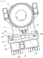
- an adapter positioning apparatus for a blade transport vehicle includes a slewing bearing unit mounted at a fixed frame disposed at an upper end of a base of the blade transport vehicle, an angle adjustment cylinder connected to the slewing bearing unit and disposed at the fixed frame so as to adjust an angle of the slewing bearing unit, a blade adapter rotatably connected to the slewing bearing unit so as to fix one end of a blade, and a positioning device disposed to interlock with the slewing bearing unit and the blade adapter so as to adjust a position of the blade adapter.
- the slewing bearing unit may include a bearing block disposed at an upper end of the fixed frame, a slewing bearing disposed at the bearing block and connected to one end of the blade adapter, and a turning drive disposed at the bearing block to rotate the slewing bearing.
- the positioning device may include a rotary plate disposed along an outer peripheral surface of the slewing bearing, a plurality of first housing brackets disposed at positions corresponding to seating grooves in the blade adapter, each having a spherical hollow formed therein, and a plurality of first hydraulic cylinders respectively having a plurality of bodies arranged circumferentially at predetermined intervals on the rotary plate and rods connected to the first housing brackets by hinge balls.
- the positioning device may include a rotary plate having a plurality of seating grooves formed circumferentially at predetermined intervals therein, the rotary plate being disposed along an outer peripheral surface of the slewing bearing, a plurality of second housing brackets disposed at positions corresponding to the seating grooves in the blade adapter, each having a spherical hollow formed therein, and a plurality of second hydraulic cylinders, each having a body disposed in the associated seating groove of the rotary plate and a rod connected to the associated second housing bracket by a hinge ball.
- the positioning device may include a rotary plate having a plurality of seating grooves formed circumferentially at predetermined intervals therein while being tapered from outside to inside, the rotary plate being disposed along an outer peripheral surface of the slewing bearing, a support bracket disposed in each of the seating grooves of the rotary plate, and having a spherical hollow formed therein, and a plurality of third hydraulic cylinders, each having a body connected to the support bracket by a hinge ball and a rod connected to the blade adapter.
- Each of the first, second, and third hydraulic cylinders may consist of four hydraulic cylinders arranged at intervals of 90 degrees on the rotary plate.
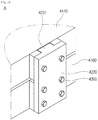
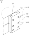
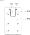
- a connection structure for a blade transport vehicle includes lower brackets arranged along the side of a lower trailer of the blade transport vehicle, upper brackets arranged along the side of a base mounted to an upper end of the lower trailer, each of the upper brackets having a seating groove formed at the center thereof, and a connection plate having a protrusion block coupled to the seating groove, the connection plate connecting each of the upper brackets and the lower bracket associated therewith.
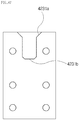
- each of the upper brackets may include a first seating portion formed at an upper side of the upper bracket and inclined from top to down, and a second seating portion formed below the first seating portion.
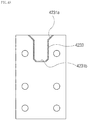
- the protrusion block of the connection plate may include a first protrusion portion having a shape corresponding to the first seating portion so as to be coupled to the first seating portion, and a second protrusion portion having a shape corresponding to the second seating portion and formed below the first protrusion portion so as to be coupled to the second seating portion.
- the blade transport vehicle may further include a buffer pad disposed between the seating groove and the protrusion block in order to reduce abrasion of a contact surface between the seating groove and the protrusion block.
- a connection structure for a blade transport vehicle includes lower brackets arranged along the side of a lower trailer of the blade transport vehicle, support slots arranged along the side of a base mounted to an upper end of the lower trailer, a fixed plate fitted into each of the support slots, and having a seating groove formed at the center thereof, and a connection plate having a protrusion block pressed against the seating groove, the connection plate connecting each of the lower brackets and the fixed plate associated therewith.
- Each of the support slots may include a pair of support beams arranged at a distance corresponding to a horizontal length of the fixed plate on the base so as to support both sides of the fixed plate, a support plate configured to connect lower portions of the support beams so as to support a lower end of the fixed plate, and first extension portions protruding outward from the support beams while facing each other.
- the fixed plate may further include second extension portions formed at both sides on a contact surface with the base and pressed against the first extension portions, and the seating groove of the fixed plate may include a first seating portion formed at an upper side of the fixed plate and having a plane shape, and a second seating portion formed below the first seating portion and having a plane shape.
- the protrusion block of the connection plate may include a first protrusion portion having a shape corresponding to the first seating portion so as to be pressed against the first seating portion, and a second protrusion portion formed below the first protrusion portion so as to be pressed against the second seating portion.
- the blade transport vehicle may further include a first elastic pad disposed on the side of the protrusion block facing the seating groove in order to reduce abrasion of a contact surface between the seating groove and the protrusion block.
- the blade transport vehicle may further include a second elastic pad disposed on the side of the fixed plate facing the connection plate in order to reduce abrasion of a contact surface between the fixed plate and the connection plate.
- the balance adjustment apparatus for a blade transport vehicle may include the following components.
- the balance adjustment apparatus for a blade transport vehicle may include a base 110 which is disposed at the upper end of a lower trailer 160 of a blade transport vehicle, a blade fixing frame 120 which is disposed on the base 110, a first moving device 200 which is disposed at the upper end of the base 110 to move the blade fixing frame 120 in the longitudinal direction of the base 110, and a second moving device 300 which is disposed at the upper end of the first moving device 200 to move the blade fixing frame 120 in the width direction of the base 110.
- the first moving device 200 may include a first guide rail 210 which is disposed at the upper end of the base 110 in the longitudinal direction of the base 110, a first plate 220 which is seated on the first guide rail 210, and a first drive unit 230 which is disposed at the upper end of the base 110 and is connected to one end of the first plate 220 so as to move the first plate 220.
- the first drive unit 230 may be a hydraulic cylinder.
- the first drive unit 230 may include first rack gears 233 which are formed on both surfaces of the base 110 in the longitudinal direction thereof on the first plate 220, first motors 234 which are disposed to face the first rack gears 233 at both sides of the base 110, and first pinion gears 235 which are connected to the shafts of the first motors 234 and are engaged with the first rack gears 233.
- the second moving device 300 may include a second guide rail 310 which is disposed at the upper end of the first plate 220 in the width direction of the base 110, a second plate 320 which is seated on the second guide rail 310 and supports the blade fixing frame 120, and a second drive unit 330 which is disposed at the upper end of the second plate 320 and moves the second plate 320.
- the second drive unit 330 may be a hydraulic cylinder.
- the second drive unit 330 may include second rack gears 333 which are formed on both surfaces of the base 110 in the width direction thereof on the second plate 320, second motors 334 which are disposed to face the second rack gears 333 at both sides of the second plate 320, and second pinion gears 335 which are connected to the shafts of the second motors 334 and are engaged with the second rack gears 333.
- the balance adjustment apparatus for a blade transport vehicle may include a balance block 130 which is spaced apart from the blade fixing frame by a predetermined distance and is disposed on the base 110, a third moving device 400 which is disposed at the upper end of the base 110 and moves the balance block 130 in the longitudinal direction of the base 110, and a fourth moving device 500 which is disposed at the upper end of the third moving device 400 and moves the balance block 130 in the width direction of the base 110.
- the third moving device 400 may include a third guide rail 410 which is formed at the upper end of the base 110 in the longitudinal direction of the base 110, a third plate 420 which is seated on the third guide rail 410, and a third drive unit 430 which is disposed at the upper end of the base 110 and is connected to one end of the third plate 420 so as to move the third plate 420.
- the third drive unit 430 may be a hydraulic cylinder.
- the third drive unit 430 may include third rack gears 433 which are formed on both surfaces of the base 110 in the longitudinal direction thereof on the third plate 420, third motors 434 which are disposed to face the third rack gears 433 at both sides of the base 110, and third pinion gears 435 which are connected to the shafts of the third motors 434 and are engaged with the third rack gears 433.
- the fourth moving device 500 may include a fourth guide rail 510 which is formed at the upper end of the third plate 420 in the width direction of the base 110, a fourth plate 520 which is seated on the fourth guide rail 510 and supports the balance block 130, and a fourth drive unit 530 which is disposed at the upper end of the fourth plate 520 and moves the fourth plate 520.
- the fourth drive unit 530 may be a hydraulic cylinder.
- the fourth drive unit 530 may include fourth rack gears 533 which are formed on both surfaces of the base 110 in the width direction thereof on the fourth plate 520, fourth motors 534 which are disposed to face the fourth rack gears 533 at both sides of the fourth plate 520, and fourth pinion gears 535 which are connected to the shafts of the fourth motors 534 and are engaged with the fourth rack gears 533.
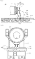
- Fig. 5 is a side view illustrating an embodiment of a balance adjustment apparatus for a blade transport vehicle according to the present invention.
- Fig. 6 is a side view illustrating a state in which the position of a blade adapter or a balance block is changed in the present invention illustrated in Fig. 5 .
- Fig. 7 is a top view illustrating a first embodiment of a position change structure of the blade adapter in the present invention illustrated in Fig. 5 .
- Fig. 8 is a top view illustrating a first embodiment of a position change structure of the balance block in the present invention illustrated in Fig. 5 .
- Fig. 9 is a top view illustrating a second embodiment of a position change structure of the blade adapter in the present invention illustrated in Fig. 5 .
- Fig. 10 is a view illustrating a rack and pinion gearing in the present invention illustrated in Fig. 9 .
- Fig. 11 is a top view illustrating a second embodiment of a position change structure of the balance block in the present invention illustrated in Fig. 5 .
- Fig. 12 is a view illustrating a rack and pinion gearing in the present invention illustrated in Fig. 11 .
- Figs. 13 and 14 are views illustrating an operation state of the blade adapter in the present invention illustrated in Fig. 5 .
- the balance adjustment apparatus for a blade transport vehicle may include a base 110, a blade fixing frame 120, a first moving device 200, and a second moving device 300.
- the base 110 may be disposed at the upper end of a lower trailer 160 of a blade transport vehicle.
- the lower trailer 160 includes a main body having a plurality of wheels arranged in multiple rows, and an upper end configured to be flat in order to transport a blade.
- the base 110 may have a flat plate shape, and be made of a steel material for improving stiffness.
- the base 110 may be coupled to the upper end of the lower trailer 160 by bolting or welding.
- the blade fixing frame 120 may be disposed on the base 110, and have a pair of columns made of a steel material.
- a slewing bearing unit 155 and a blade adapter 151 may be mounted on the upper end of the blade fixing frame 120.
- An angle adjustment cylinder 140 may be connected to the slewing bearing unit 155 between the pair of steel columns.
- the slewing bearing unit 155 may include a slewing bearing 152 and a bearing block 153.
- the slewing bearing 152 is rotatably disposed in the bearing block 153, and a turning drive 154 is mounted to one end of the bearing block 153 so as to rotate the slewing bearing 152.
- the blade adapter 151 is mounted to one side of the slewing bearing 152 and rotates along with the slewing bearing 152 by the turning drive 154.
- the blade adapter 151 serves to fix a heavy blade mounted to a wind turbine.
- the user may circumferentially adjust the angle of the blade mounted onto the blade adapter 151 by rotating the slewing bearing 152, and may vertically adjust the angle of the blade mounted onto the blade adapter 151 by operating the angle adjustment cylinder 140.
- the first moving device 200 may be disposed at the upper end of the base 110 and move the blade fixing frame 120 in the longitudinal direction of the base 110.
- the first moving device 200 may include a first guide rail 210, a first plate 220, and a first drive unit 230.
- the first guide rail 210 may be disposed at the upper end of the base 110 in the longitudinal direction of the base 110. Referring to Fig. 7 , it can be seen that the first guide rail 210 consists of a pair of guide rails in the longitudinal direction of the vehicle on the base 110. Of course, the number of first guide rails is not limited thereto. Stoppers 211 are installed to both ends of the first guide rail 210 in order to restrict the movement of the first plate 220. The first plate 220 moving along the upper end of the first guide rail 210 is not separated from the first guide rail 210 by the stoppers 211.
- the first plate 220 is seated on the first guide rail 210, and has a seating groove 223 (see Fig. 13 ) which is formed in the lower end thereof and has a shape corresponding to the first guide rail 210 so as to be seated on the first guide rail 210.
- a typical ball bearing unit may be mounted to the first plate 220 such that the first plate 220 smoothly moves on the upper end of the first guide rail 210.
- the first drive unit 230 may be disposed adjacent to the first plate 220 at the upper end of the base 110, and may be connected to one end of the first plate 220 so as to move the first plate 220. Referring to Fig. 7 , it can be seen that the first drive unit 230 is disposed on the base 110. In the embodiment of the present invention, the first drive unit 230 may be a hydraulic cylinder 231.
- the body of the hydraulic cylinder 231 may be bolted to the upper end of the base 110, and the rod of the hydraulic cylinder 231 may be coupled to one end of the first plate 220.
- the first plate 220 may move on the first guide rail 210 by the forward or rearward movement of the rod of the hydraulic cylinder 231.
- the second moving device 300 may be disposed at the upper end of the first moving device 200 and move the blade fixing frame 120 in the width direction of the base 110.
- the second moving device 300 may include a second guide rail 310, a second plate 320, and a second drive unit 330.
- the second guide rail 310 may be disposed at the upper end of the base 110 in the width direction of the base 110. Also, stoppers 311 may be installed to both ends of the second guide rail 310 in order to restrict the movement of the first plate 220.
- the second plate 320 may be seated on the second guide rail 310 and support the blade fixing frame 120. Referring to Fig. 7 again, it can be seen that the blade fixing frame 120 having a pair of columns is disposed at the upper end of the second plate 320.
- the second plate 320 has a seating groove 328 (see Fig. 5 ) which is formed in the lower end thereof so as to be seated on the second guide rail 310.
- a typical ball bearing unit may be mounted into the seating groove 328 in order to smoothly move the second plate 320.
- the second drive unit 330 may be disposed at the upper end of the second plate 320 and move the second plate 320.
- the second drive unit 330 may be a hydraulic cylinder 331.
- the hydraulic cylinder 331 may consist of a pair of hydraulic cylinders disposed at the upper end of the second plate 320.
- the body of the hydraulic cylinder 331 may be fixed to the upper end of the second plate 320 by bolting, and the rod of the hydraulic cylinder 331 may be coupled to a support block 332 disposed at the upper end of the first plate 220. Accordingly, the second plate 320 moves in such a way to be pushed or pulled by the forward or rearward movement of the rod of the hydraulic cylinder 331.
- the first drive unit 230 may include first rack gears 233, first motors 234, and first pinion gears 235, as illustrated in Figs. 9 and 10 .
- the first rack gears 233 may be formed on both surfaces of the base 110 in the longitudinal direction thereof on the first plate 220.
- the first motors 234 may be disposed to face the first rack gears 233 at both sides of the base 110. As illustrated in Fig. 10 , each of the first motors 234 may be mounted to a fixing bracket 236 by bolting, and the shaft thereof may be disposed downward.
- Each of the first pinion gears 235 may be connected to the shaft of the associated first motor 234 so as to be engaged with the associated first rack gear 233.
- the first plate 220 horizontally moves in the longitudinal direction of the base 110 by the interaction of the first rack gear 233 and the first pinion gear 235 according to the rotation direction of the shaft of the first motor 234.
- the second drive unit 330 may include second rack gears 333, second motors 334, and second pinion gears 335.
- the second rack gears 333 may be formed on both surfaces of the base 110 in the width direction thereof on the second plate 320.
- the second motors 334 may be disposed to face the second rack gears 333 at both sides of the second plate 320.
- Each of the second motors 334 may be mounted to a fixing bracket by bolting, and the shaft thereof may be disposed downward.
- Each of the second pinion gears 335 may be connected to the shaft of the associated second motor 334 so as to be engaged with the associated second rack gear 333.
- the second plate 320 horizontally moves in the width direction of the base 110 by the interaction of the second rack gear 333 and the second pinion gear 335 according to the rotation direction of the shaft of the second motor 334.
- the balance adjustment apparatus for a blade transport vehicle may further include a balance block 130, a third moving device 400, and a fourth moving device 500.
- the balance block 130 performs a balance function so as to correspond to the weight of the blade for preventing the overturn of the vehicle.
- the balance block 130 may be spaced apart from the blade fixing frame by a predetermined distance and be disposed on the base 110. Referring to Fig. 5 , it can be seen that the balance block 130 is disposed rearward of the vehicle from the blade fixing frame.
- the balance block 130 may be a weight or other devices.
- the third moving device 400 may be disposed at the upper end of the base 110 and move the balance block 130 in the longitudinal direction of the base 110.
- the third moving device 400 may include a third guide rail 410, a third plate 420, and a third drive unit 430.
- the third guide rail 410 may be disposed at the upper end of the base 110 in the longitudinal direction of the base 110. Referring to Fig. 8 , it can be seen that the third guide rail 410 consists of a pair of guide rails in the longitudinal direction of the vehicle on the base 110. Of course, the number of third guide rails is not limited thereto. Stoppers 411 are installed to both ends of the third guide rail 410 in order to restrict the movement of the third plate 420. The third plate 420 moving along the upper end of the third guide rail 410 is not separated from the third guide rail 410 by the stoppers 411.
- the third plate 420 is seated on the third guide rail 410.
- the third plate 420 may have a seating groove which is formed in the lower end thereof and has a shape corresponding to the third guide rail 410 so as to be seated on the third guide rail 410, and a typical ball bearing unit may be mounted to the third plate 420 such that the third plate 420 smoothly moves on the upper end of the third guide rail 410.
- the third drive unit 430 may be disposed adjacent to the third plate 420 at the upper end of the base 110, and may be connected to one end of the third plate 420 so as to move the third plate 420. Referring to Fig. 8 again, it can be seen that the third drive unit 430 is disposed on the base 110. In the embodiment of the present invention, the third drive unit 430 may be a hydraulic cylinder 431.
- the body of the hydraulic cylinder 431 may be bolted to the upper end of the base 110, and the rod of the hydraulic cylinder 431 may be coupled to one end of the third plate 420.
- the third plate 420 may move on the third guide rail 410 by the forward or rearward movement of the rod of the hydraulic cylinder 431.
- the fourth moving device 500 may be disposed at the upper end of the third moving device 400 and move the balance block 130 in the width direction of the base 110.
- the fourth moving device 500 may include a fourth guide rail 510, a fourth plate 520, and a fourth drive unit 530.
- the fourth guide rail 510 may be disposed at the upper end of the third plate 420 in the width direction of the base 110. Also, stoppers 511 may be installed to both ends of the fourth guide rail 510 in order to restrict the movement of the fourth plate 520.
- the fourth plate 520 may be seated on the fourth guide rail 510 and support the balance block 130. Referring to Fig. 8 again, it can be seen that the balance block 130 is disposed at the upper end of the fourth plate 520. Although not shown in the drawing, the fourth plate 520 may have a seating groove which is formed in the lower end thereof so as to be seated on the fourth guide rail 510, and a typical ball bearing unit may be mounted into the seating groove in order to smoothly move the fourth plate 520.
- the fourth drive unit 530 may be disposed at the upper end of the fourth plate 520 and move the fourth plate 520.
- the fourth drive unit 530 may be a hydraulic cylinder 531.
- the hydraulic cylinder 531 may consist of a pair of hydraulic cylinders disposed at the upper end of the fourth plate 520.
- the body of the hydraulic cylinder 531 may be fixed to the upper end of the fourth plate 520 by bolting, and the rod of the hydraulic cylinder 531 may be coupled to a support block 532 disposed at the upper end of the third plate 420. Accordingly, the fourth plate 520 moves in such a way to be pushed or pulled by the forward or rearward movement of the rod of the hydraulic cylinder 531.
- the third drive unit 430 may include third rack gears 433, third motors 434, and third pinion gears 435, as illustrated in Figs. 11 and 12 .
- the third rack gears 433 may be formed on both surfaces of the base 110 in the longitudinal direction thereof on the third plate 420.
- the third motors 434 may be disposed to face the third rack gears 433 at both sides of the base 110. As illustrated in Fig. 12 , each of the third motors 434 may be mounted to a fixing bracket 436 by bolting, and the shaft thereof may be disposed downward.
- Each of the third pinion gears 435 may be connected to the shaft of the associated third motor 434 so as to be engaged with the associated third rack gear 433.
- the third plate 420 horizontally moves in the longitudinal direction of the base 110 by the interaction of the third rack gear 433 and the third pinion gear 435 according to the rotation direction of the shaft of the third motor 434.
- the fourth drive unit 530 may include fourth rack gears 533, fourth motors 534, and fourth pinion gears 535.
- the fourth rack gears 533 may be formed on both surfaces of the base 110 in the width direction thereof on the fourth plate 520.
- the fourth motors 534 may be disposed to face the fourth rack gears 533 at both sides of the third plate 420.
- Each of the fourth motors 534 may be mounted to a fixing bracket (not shown) by bolting, and the shaft thereof may be disposed downward.
- Each of the fourth pinion gears 535 may be connected to the shaft of the associated fourth motor 534 so as to be engaged with the associated fourth rack gear 533.
- the fourth plate 520 horizontally moves in the width direction of the base 110 by the interaction of the fourth rack gear 533 and the fourth pinion gear 535 according to the rotation direction of the shaft of the fourth motor 534.
- the balance adjustment apparatus for a blade transport vehicle having the above configuration has an operation structure as illustrated in Figs. 5, 6 , 13 , and 14 .
- the user may move the blade fixing frame 120, to which the blade adapter 151 and the slewing bearing unit 155 are mounted, by driving the first drive unit 230. That is, as illustrated in Figs. 5 and 6 , when the first drive unit 230 configured as the hydraulic cylinder 231 is operated, the position of the first plate 220 is changed by the forward or rearward movement of the rod of the hydraulic cylinder 231. Since the first plate 220 moves forward or rearward along the first guide rail 210, the first plate 220 may stably move in the longitudinal direction of the base 110.
- the user may adjust the position of the balance block 130 in order to adjust the center of gravity of the vehicle in response to the movement of the blade fixing frame 120.
- the user moves the balance block 130 by driving the third drive unit 430. That is, as illustrated in Figs. 5 and 6 , when the third drive unit 430 configured as the hydraulic cylinder 431 is operated, the position of the balance block 130 is changed by the forward or rearward movement of the rod of the hydraulic cylinder 431. Since the third plate 420 moves forward or rearward along the third guide rail 410, the third plate 420 may stably move in the longitudinal direction of the base 110.
- the user adjusts the position of the second plate 320 in a direction opposite to the inclined direction by operating the second drive unit 330 configured as the hydraulic cylinder 331.
- the hydraulic cylinder 331 When the hydraulic cylinder 331 is operated in the state in which the rod of the hydraulic cylinder 331 is supported by the support block 332, the second plate 320 moves in the direction opposite to the inclined direction and the blade fixing frame 120 disposed at the upper end of the second plate 320 also moves in the direction opposite to the inclined direction.
- the center of gravity of the vehicle is moved in the direction opposite to the inclined direction by the blade, the risk that the blade transport vehicle overturns is lowered.
- the center of gravity applied to the vehicle is adjusted by the load of the blade by moving the third and fourth plates 420 and 520, which support the balance block 130, in the direction opposite to the inclined direction in the same operation manner.
- the blade since the center of gravity of the vehicle is maintained by properly changing the position of the blade depending on the state of the road or the ground, the blade may be safely transported to the region of wind power equipment.
- the angle adjustment apparatus for a blade transport vehicle may include the following components.
- the angle adjustment apparatus for a blade transport vehicle may include a base 1110 which is disposed at the upper end of a lower trailer of a blade transport vehicle, a blade fixing frame 1120 which is disposed on the base 1110, an elevation plate 1200 which is disposed at the upper end of the base 1110 and supports the blade fixing frame 1120, and elevation devices which are disposed at both sides of the base 1110 in the width direction thereof and are connected to the lower end of the elevation plate 1200.
- the elevation devices include internal elevation devices 1300 which are disposed inside both sides of the base in the width direction thereof.
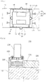
- Each of the internal elevation devices 1300 may include a first angle hydraulic cylinder 1310 which is disposed in a first seating groove formed in the base 1110, and a first support bracket 1320 which is disposed at the lower end of the elevation plate 1200 and is connected to the rod of the first angle hydraulic cylinder 1310 by a hinge.
- the internal elevation device 1300 may include a second seating groove 1340 which is formed in the base 1110 and is tapered from top to down in the width direction of the base 1110, a second angle hydraulic cylinder 1370 which has a body disposed in the second seating groove 1340 and a rod connected to the lower end of the elevation plate 1200, and a second support bracket 1350 which is disposed at the lower end in the second seating groove 1340 and is connected to the body of the second angle hydraulic cylinder 1370 by a hinge.
- a second seating groove 1340 which is formed in the base 1110 and is tapered from top to down in the width direction of the base 1110
- a second angle hydraulic cylinder 1370 which has a body disposed in the second seating groove 1340 and a rod connected to the lower end of the elevation plate 1200
- a second support bracket 1350 which is disposed at the lower end in the second seating groove 1340 and is connected to the body of the second angle hydraulic cylinder 1370 by a hinge.
- the elevation devices include external elevation devices 1400 which are disposed outside both sides of the base in the width direction thereof.
- Each of the external elevation devices 1400 may include a third support bracket 1420 which is disposed at the lower end of the elevation plate 1200, and a third angle hydraulic cylinder 1410 which has a body disposed at the outer end of the base 1110 in the width direction thereof and a rod connected to the third support bracket 1420 by a hinge.
- the external elevation device 1400 may include a fourth support bracket 1440 which is disposed on the tapered portion 1115 of the base 1110, and a fourth angle hydraulic cylinder 1460 which has a body connected to the fourth support bracket 1440 by a hinge and a rod connected to the lower end of the elevation plate 1200.
- the angle adjustment apparatus for a blade transport vehicle may further include a horizontal gyro sensor 1550 which is disposed on the elevation plate 1200 or the base 1110 so as to measure an angle of inclination of the blade fixing frame 1120.
- the angle adjustment apparatus for a blade transport vehicle may further include a controller 1500 which interlocks with the horizontal gyro sensor 1550 and adjusts an angle of arrangement of the elevation plate 1200.
- the controller 1500 may include an angle measurement device 1510 which is connected to the horizontal gyro sensor 1550 and measures the angle of inclination of the blade fixing frame 1120, an angle conversion device 1520 which converts the angle value received from the angle measurement device 1510 into an amount of hydraulic pressure, and a hydraulic drive device 1530 which adjusts the first angle hydraulic cylinder 1310 or the second angle hydraulic 1370 based on the amount of hydraulic pressure received from the angle conversion device 1520.
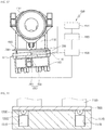
- Fig. 15 is a side view illustrating a first embodiment of an angle adjustment apparatus for a blade transport vehicle according to the present invention.
- Figs. 16 and 17 are views illustrating an operation state of the present invention illustrated in Fig. 15 .
- Figs. 18 and 19 are views illustrating an embodiment of an internal elevation device in the present invention illustrated in Fig. 15 .
- Figs. 20 and 21 are views illustrating another embodiment of an internal elevation device in the present invention illustrated in Fig. 15 .
- the angle adjustment apparatus for a blade transport vehicle may include a base 1110, a blade fixing frame 1120, an elevation plate 1200, and internal elevation devices 1300 which correspond to one of elevation devices.
- the base 1110 may be disposed at the upper end of a lower trailer 1160 of a blade transport vehicle.
- the lower trailer 1160 includes a main body having a plurality of wheels arranged in multiple rows, and an upper end configured to be flat in order to transport a blade.
- the base 1110 may have a flat plate shape, and be made of a steel material for improving stiffness.
- the base 1110 may be coupled to the upper end of the lower trailer 1160 by bolting or welding.
- the blade fixing frame 1120 may be disposed on the base 1110, and have a pair of columns made of a steel material.
- a slewing bearing unit 1155 and a blade adapter 1151 may be mounted on the upper end of the blade fixing frame 1120.
- An angle adjustment cylinder 1140 may be connected to the slewing bearing unit 1155 between the pair of steel columns.
- the slewing bearing unit 1155 may include a slewing bearing 1152 and a bearing block 1153.
- the slewing bearing 1152 is rotatably disposed in the bearing block 1153, and a turning drive 1154 is mounted to one end of the bearing block 1153 so as to rotate the slewing bearing 1152.
- the blade adapter 1151 is mounted to one side of the slewing bearing 1152 and rotates along with the slewing bearing 1152 by the turning drive 1154.
- the blade adapter 1151 serves to fix a heavy blade mounted to a wind turbine.
- the user may circumferentially adjust the angle of the blade mounted onto the blade adapter 1511 by rotating the slewing bearing 1152, and may vertically adjust the angle of the blade mounted onto the blade adapter 1151 by operating the angle adjustment cylinder 1140.
- the elevation plate 1200 may be disposed at the upper end of the base 1110 and support the blade fixing frame 1120.
- the elevation plate 1200 may have a flat shape and be made of a steel material.
- the internal elevation devices 1300 may be disposed inside both sides of the base 1110 in the width direction thereof and be connected to the lower end of the elevation plate 1200.
- each of the internal elevation devices 1300 may include a first angle hydraulic cylinder 1310 and a first support bracket 1320.
- the first angle hydraulic cylinder 1310 may be disposed in a first seating groove 1119 formed in the base 1110.
- the first support bracket 1320 may be disposed at the lower end of the elevation plate 1200.
- the rod of the first angle hydraulic cylinder 1310 may be connected to the first support bracket 1320 by a hinge 1330.
- the first seating groove 1119 may have a square shape in the base 1110 and consist of four seating grooves.
- the first angle hydraulic cylinder 1310 disposed in the first seating groove 1119 may consist of four hydraulic cylinders. This enables the first angle hydraulic cylinders to support the respective corners of the elevation plate 1200.
- the number of first angle hydraulic cylinders is not limited thereto. The number of first angle hydraulic cylinders may be six, eight, or the like in order to the intermediate portions of the elevation plate 1200 in addition to the corners thereof.
- the internal elevation device 1300 may include a second seating groove 1340, a second angle hydraulic cylinder 1370, and a second support bracket 1350, as illustrated in Figs. 20 and 21 .
- the second seating groove 1340 may be formed in the base 1110 and be tapered from top to down in the width direction of the base 1110.
- the body of the second angle hydraulic cylinder 1370 may be disposed in the second seating groove 1340, and the rod of the second angle hydraulic cylinder 1370 may be connected to the lower end of the elevation plate 1200 by bolting or welding.
- the second support bracket 1350 may be disposed at the lower end in the second seating groove 1340 and be connected to the body of the second angle hydraulic cylinder 1370 by a hinge 360.
- the user operates the second angle hydraulic cylinder 1370 to adjust the angle of the elevation plate 1200. Since the body of the second angle hydraulic cylinder 1370 is connected to the second support bracket 1350 by the hinge 360, a torsional load does not occur according to the change of the angle of the elevation plate 1200.
- the second angle hydraulic cylinder 1370 may rotate in the second seating groove 1340.
- the second seating groove 1340 may consist of four seating grooves to support the respective corners of the elevation plate 1200.
- the second angle hydraulic cylinder 1370 may also consist of four hydraulic cylinders and support the elevation plate 1200 having a square flat shape.
- the number of second angle hydraulic cylinders is not limited thereto. The number of second angle hydraulic cylinders may be six, eight, or the like in order to the intermediate portions of the elevation plate 1200 in addition to the corners thereof.
- the angle adjustment apparatus for a blade transport vehicle may further include a horizontal gyro sensor 1550 which is disposed on the elevation plate 1200 so as to measure an angle of inclination of the blade fixing frame 1120.
- the angle adjustment apparatus for a blade transport vehicle may further include a controller 1500 which interlocks with the horizontal gyro sensor 1550 and automatically adjusts an angle of arrangement of the elevation plate 1200.
- the controller 1500 may include an angle measurement device 1510, an angle conversion device 1520, and a hydraulic drive device 1530.
- a first horizontal sensor 1551 is mounted to the elevation plate 1200 and a second horizontal sensor 1553 is mounted to the base 1110. If the blade transport vehicle is stopped or travels on the slope, there is a risk that the vehicle leans in an inclined direction and overturns due to the blade having a weight of several tens of tons.
- the angle measurement device 1510 is connected to the horizontal gyro sensor 1550 and measures the angle of inclination of the blade fixing frame 1120 in real time.
- the first horizontal sensor 1551 measures a gradient of the elevation plate 1200 and the second horizontal sensor 1553 measures a gradient of the base 1110.
- the angle measurement device 1510 transmits the above information to the angle conversion device 1520, and the angle conversion device 1520 converts the angle value, which is measured by and received from the angle measurement device 1510, into an amount of hydraulic pressure.
- the hydraulic drive device 1530 drives the first or second angle hydraulic cylinder 1310 or 1370.
- the elevation plate 1200 is located horizontally again on the slope by the operation of the first angle hydraulic cylinder 1310 disposed at one side of the base 1110. Whether or not the angle adjustment of the elevation plate 1200 is completed is performed by comparing the angle values measured by the first and second horizontal sensors 1551 and 1553. That is, when the angle adjustment device 1510 compares the angle values measured by the first and second horizontal sensors 1551 and 1553 in real time and the angle value input from the first horizontal sensor 151 is "0", the elevation plate 1200 is determined to be located horizontally. Therefore, the controller transmits a signal to the hydraulic drive device 1530, and the hydraulic drive device 1530 stops the operation of the first angle hydraulic cylinder 1310. Of course, the operation of the second angle hydraulic cylinder 1370 is performed similar to the above case.
- Figs. 22 and 23 are views illustrating an operation state of a second embodiment of a blade transport vehicle according to the present invention.
- Figs. 24 and 25 are views illustrating an embodiment of an external elevation device in the present invention illustrated in Fig. 22 .
- Figs. 26 and 27 are views illustrating another embodiment of an external elevation device in the present invention illustrated in Fig. 22 .
- the angle adjustment apparatus for a blade transport vehicle may include a base 1110, a blade fixing frame 1120, an elevation plate 1200, and external elevation devices 1400 which correspond to one of elevation devices. Since a lower trailer 1160, a slewing bearing unit 1155, an angle adjustment cylinder 1140, and a blade adapter 1151 in addition to the base 1110 and the blade fixing frame 1120 are similar to those of the first embodiment of the present invention, the basic description thereof will be omitted.
- the elevation plate 1200 may be disposed at the upper end of the base 1110 and support the blade fixing frame 1120.
- the elevation plate 1200 may have a flat shape and be made of a steel material.
- each of the external elevation devices 1400 may be disposed outside both sides of the base in the width direction thereof and be connected to the lower end of the elevation plate 1200.
- each of the external elevation devices 1400 may include a third angle hydraulic cylinder 1410 and a third support bracket 1420.
- the body of the third angle hydraulic cylinder 1410 may be bolted to the outer end of the base 1110.
- the third support bracket 1420 maybe disposed at the lower end of the elevation plate 1200.
- the rod of the third angle hydraulic cylinder 1410 may be connected to the third support bracket 1420 by a hinge 1430.
- the third angle hydraulic cylinder 1410 may consist of a total of four hydraulic cylinders, in which case two hydraulic cylinders are disposed on each of both outer ends of the base 1110. This enables the third angle hydraulic cylinders to support the respective corners of the elevation plate 1200.
- the number of third angle hydraulic cylinders is not limited thereto. The number of third angle hydraulic cylinders may be six, eight, or the like in order to the intermediate portions of the elevation plate 1200 in addition to the corners thereof.
- the rod of the third angle hydraulic cylinder 1410 When the user operates one third angle hydraulic cylinder 1410 on a slope in order to stabilize the arrangement position of the blade, the rod of the third angle hydraulic cylinder 1410 is lifted and the elevation plate 1200 is inclined. In this case, since the lower end of the elevation plate 1200 is connected to the rod of the third angle hydraulic cylinder 1410 by the hinge 1430 and the third support bracket 1420, a torsional load does not occur in the rod of the third angle hydraulic cylinder 1410 even though the elevation plate 1200 is inclined.
- the external elevation device 1400 may include a fourth angle hydraulic cylinder 1460, and a fourth support bracket 1440, as illustrated in Figs. 26 and 27 .
- Each of both outer ends of the base 1110 is formed as a tapered portion 1115 which is tapered from down to top in the width direction of the base 1110.
- the fourth support bracket 1440 may be disposed on the tapered portion 1115 of the base 1110.
- the body of the fourth angle hydraulic cylinder 1460 may be connected to the fourth support bracket 1440 by a hinge 1450, and the rod of the fourth angle hydraulic cylinder 1460 may be coupled to the lower end of the elevation plate 1200 by bolting or welding.
- the user operates the fourth angle hydraulic cylinder 1460 to adjust the angle of the elevation plate 1200. Since the body of the fourth angle hydraulic cylinder 1460 is connected to the fourth support bracket 1440 by the hinge 1450, a torsional load does not occur according to the change of the angle of the elevation plate 1200.
- the fourth angle hydraulic cylinder 1460 may rotate on the side of the base 1110.
- the fourth support bracket 1440 may consist of four brackets to support the respective corners of the elevation plate 1200, as illustrated in Fig. 26 .
- the fourth angle hydraulic cylinder 1460 may also consist of four hydraulic cylinders and support the elevation plate 1200 having a square flat shape.
- the number of fourth angle hydraulic cylinders is not limited thereto.
- the number of fourth angle hydraulic cylinders may be six, eight, or the like in order to the intermediate portions of the elevation plate 1200 in addition to the corners thereof.
- the angle adjustment apparatus for a blade transport vehicle may further include a horizontal gyro sensor 1550 which is disposed on the elevation plate 1200 so as to measure an angle of inclination of the blade fixing frame 1120.
- the angle adjustment apparatus for a blade transport vehicle may further include a controller 1500 which interlocks with the horizontal gyro sensor 1550 and automatically adjusts an angle of arrangement of the elevation plate 1200.
- the controller 1500 may include an angle measurement device 1510, an angle conversion device 1520, and a hydraulic drive device 1530.
- a first horizontal sensor 1551 is mounted to the elevation plate 1200 and a second horizontal sensor 1553 is mounted to the base 1110. If the blade transport vehicle is stopped or travels on the slope, there is a risk that the vehicle leans in an inclined direction and overturns due to the blade having a weight of several tens of tons.
- the angle measurement device 1510 is connected to the horizontal gyro sensor 1550 and measures the angle of inclination of the blade fixing frame 1120 in real time.
- the first horizontal sensor 1551 measures a gradient of the elevation plate 1200 and the second horizontal sensor 1553 measures a gradient of the base 1110.
- the angle measurement device 1510 transmits the above information to the angle conversion device 1520, and the angle conversion device 1520 converts the angle value, which is measured by and received from the angle measurement device 1510, into an amount of hydraulic pressure.
- the hydraulic drive device 1530 drives the third or fourth angle hydraulic cylinder 1410 or 1460.
- the elevation plate 1200 is located horizontally again on the slope by the operation of the first angle hydraulic cylinder 1310 disposed at one side of the base 1110. Whether or not the angle adjustment of the elevation plate 1200 is completed is performed by comparing the angle values measured by the first and second horizontal sensors 1551 and 1553. That is, when the angle adjustment device 1510 compares the angle values measured by the first and second horizontal sensors 1551 and 1553 in real time and the angle value input from the first horizontal sensor 151 is "0", the elevation plate 1200 is determined to be located horizontally. Therefore, the controller transmits a signal to the hydraulic drive device 1530, and the hydraulic drive device 1530 stops the operation of the third angle hydraulic cylinder 1410. Of course, the operation of the fourth angle hydraulic cylinder 1460 is performed similar to the above case.
- the safety control system for a blade transport vehicle may include the following components.
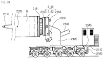
- the safety control system for a blade transport vehicle may include a wind vane and anemometer 2310 which is disposed at the end of a blade so as to measure a wind direction and a wind speed applied to the blade, at least one acceleration sensor 2320 which is disposed in the longitudinal direction of the blade to measure the rolling of the blade, and a controller 2200 which adjusts the position of the blade based on the values obtained by measuring the wind direction and speed applied to the blade and the rolling of the blade.
- the controller 2200 may include a wind direction and speed measurement device 2210 which receives information on the wind direction and speed applied to the blade from the wind vane and anemometer 2310 in real time, and an acceleration measurement device 2220 which receives information on the rolling acceleration generated in the blade from the acceleration sensor 2320 in real time.
- the safety control system for a blade transport vehicle may further include a first angle sensor 2330 which is disposed in a slewing bearing unit of a blade transport vehicle in order to measure an angle of inclination of the blade to the rod of a hydraulic cylinder 2140.
- the safety control system for a blade transport vehicle may further include a second angle sensor 2340 which is disposed in a base 2110 of the blade transport vehicle in order to measure an angle of inclination of the vehicle to the ground.
- the controller 2200 may further include an angle measurement device 2230 which receives information on the angle of inclination of the blade from the first angle sensor 2330 and information on the angle of inclination of the vehicle from the second angle sensor 2340.
- the controller 2200 may further include a conversion device 2240 which converts the information, received from the wind direction and speed measurement device 2210, the acceleration measurement device 2220, and the angle measurement device 2230, into an amount of hydraulic pressure corresponding to the changed angle value of the blade or the changed rotation value of the blade.
- a conversion device 2240 which converts the information, received from the wind direction and speed measurement device 2210, the acceleration measurement device 2220, and the angle measurement device 2230, into an amount of hydraulic pressure corresponding to the changed angle value of the blade or the changed rotation value of the blade.
- the controller 2200 may further include a hydraulic drive device 2250 which adjusts the hydraulic cylinder 2140 according to the amount of hydraulic pressure received from the conversion device 2240, and a rotation drive device 2260 which rotates a slewing bearing 2153 according to the changed rotation value received from the conversion device 2240.
- the controller 2200 may further include a limit device 2270 which drives the conversion device 2240 only when the measured values exceed the preset limit values of wind direction and speed applied to the blade, the preset limit rolling acceleration value of the blade, and the preset limit gradient value of the blade.
- a limit device 2270 which drives the conversion device 2240 only when the measured values exceed the preset limit values of wind direction and speed applied to the blade, the preset limit rolling acceleration value of the blade, and the preset limit gradient value of the blade.
- Fig. 29 is a view illustrating an embodiment of a safety control system for a blade transport vehicle according to the present invention.
- Fig. 30 is a control block diagram of the present invention illustrated in Fig. 29 .
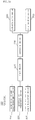
- Fig. 31 is a flowchart of the present invention illustrated in Fig. 30 .
- Figs. 32 and 33 are views illustrating a state in which a blade is rotated corresponding to a wind direction and a wind speed or the rolling of the blade by the wind direction and the wind speed.
- Figs. 34 and 35 are views illustrating a state in which a blade is rotated corresponding to a gradient of the ground or the rolling of the blade by the gradient of the ground.
- the safety control system for a blade transport vehicle may include a wind vane and anemometer 2310, an acceleration sensor 2320, a first angle sensor 2330, a second angle sensor 2340, and a controller 2200.
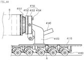
- a blade transport vehicle applied to the present invention may include a lower trailer 2160, a base 2110, a blade fixing frame 2120, a hydraulic cylinder 2140, a slewing bearing unit 2155, and a blade adapter 2151, as illustrated in Fig. 29 .
- the base 2110 may be disposed at the upper end of the lower trailer 2160 of the blade transport vehicle.
- the lower trailer 2160 includes a main body having a plurality of wheels arranged in multiple rows, and an upper end configured to be flat in order to transport a blade.
- the base 2110 may have a flat plate shape, and be made of a steel material for improving stiffness.
- the base 2110 may be coupled to the upper end of the lower trailer 2160 by bolting or welding.
- the lower trailer 2160 may be connected to a tow truck having an engine, a driver seat, etc., so as to be moved thereby.
- the blade fixing frame 2120 may be disposed on the base 2110, and have a pair of columns made of a steel material.
- a slewing bearing unit 2155 and a blade adapter 2151 may be mounted on the upper end of the blade fixing frame 2120.
- An angle adjustment cylinder 2140 may be connected to the slewing bearing unit 2155 between the pair of steel columns.
- the slewing bearing unit 2155 may include a slewing bearing 2152 and a bearing block 2153.
- the slewing bearing 2152 is rotatably disposed in the bearing block 2153, and a turning drive 2154 is mounted to one end of the bearing block 2153 so as to rotate the slewing bearing 2152.
- the blade adapter 2151 to which one end of the blade is assembled, is mounted to one side of the slewing bearing 2152 and rotates along with the slewing bearing 2152 by the turning drive 2154.
- the blade adapter 2151 serves to fix a heavy blade mounted to a wind turbine.
- the user may circumferentially adjust the angle of the blade mounted onto the blade adapter 2151 by rotating the slewing bearing 2152, and may vertically adjust the angle of the blade mounted onto the blade adapter 2151 by operating the angle adjustment cylinder 2140.
- the wind vane and anemometer 2310 may be disposed at the other end of the blade so as to measure a wind direction and a wind speed applied to the blade. Referring to Fig. 29 , it can be seen that the wind vane and anemometer 2310 is mounted to the tip of the blade. This is because the tip of the blade is largely affected by the wind direction and the wind speed.
- one end of the blade is fixedly assembled to the blade adapter 2151, it is not nearly affected by the wind direction and the wind speed.
- the other end of the blade is fixed by a belt or a wire, external force is generated in the blade by substantial wind when the specific curved surface of the blade is directed to windward. This external force acts as force that deteriorates the fixing force of the blade and changes the position of the blade.
- the strong wind speed acts as external force that pushes the blade.
- This external force consistently acts as a load that deteriorates the fixing force of the blade and separates the blade from the blade adapter 2151.
- the wind vane and anemometer 2310 is disposed at the tip of the blade to measure the wind direction and speed applied to the blade, and the controller 2200 adjusts the arrangement position of the blade by adjusting the angle of rotation of the blade adapter 2151 based on the measured wind direction and speed value, as illustrated in Figs. 32 and 33 . That is, since the blade rotated by wind has a curved shape, it is possible to reduce external force (load) due to wind by changing the surface of the blade facing the wind.
- the at least one acceleration sensor 2320 may be disposed in the longitudinal direction of the blade to measure the rolling of the blade.
- the rolling of the blade may occur due to the wind direction and speed applied to the blade while the vehicle is traveling, or may occur due to the gradient of the road and when the vehicle travels on the slope.
- the at least one acceleration sensor 2320 is disposed in the longitudinal direction of the blade to measure the rolling of the blade, and the controller 2200 adjusts the arrangement position of the blade by adjusting the angle of rotation of the blade adapter 2151 based on the measured rolling value of the blade, as illustrated in Figs. 34 and 35 .
- the first angle sensor 2330 may be disposed in the slewing bearing unit 2155 in order to measure an angle of inclination of the blade to the rod of the hydraulic cylinder 2140.
- the second angle sensor 2340 may be disposed in the base 2110 of the blade transport vehicle in order to measure an angle of inclination of the vehicle to the ground.
- the first angle sensor 2330 is disposed at the lower portion of the bearing block 2152 constituting the slewing bearing unit 2155.
- the angle of the blade adapter 2151 assembled to the slewing bearing unit 2155 is also adjusted.
- the angle of the blade mounted to the blade adapter 2151 is also determined.
- the first angle sensor 2330 measures whether the blade is located horizontally to the center line of the rod of the hydraulic cylinder 2140 or whether the blade is lifted at some angle in real time.
- the second angle sensor 2340 is mounted on the base 2110 disposed at the upper end of the lower trailer 2160.
- the second angle sensor 2340 measures an angle formed by the ground and the vehicle.
- the controller 2200 drives the hydraulic cylinder 2140 and changes an angle of arrangement of the blade so as to stably adjust the center of gravity of the blade in response to a current gradient, based on the angle values of the blade and the vehicle received from the first and second angle sensors 2330 and 2340.
- the controller 2200 performs a function that measures the values of wind direction and speed applied to the blade, the rolling value of the blade, and the gradient value of the blade and properly adjusts the position of the blade.
- the controller 2200 may include a wind direction and speed measurement device 2210, an acceleration measurement device 2220, an angle measurement device 2230, a conversion device 2240, a hydraulic drive device 2250, a rotation drive device 2260, and a limit device 2270.
- the wind direction and speed measurement device 2210 receives information on the wind direction and speed applied to the blade from the wind vane and anemometer 2310 in real time (S1).
- the acceleration measurement device 2220 receives information on the rolling acceleration generated in the blade from the acceleration sensor 2320 in real time (S3).
- the angle measurement device 2230 receives information on the angle of inclination of the blade from the first angle sensor 2330 (S7) and receives information on the angle of inclination of the vehicle from the second angle sensor 2340 (S8).
- the limit device 2270 may drive the conversion device 2240 only when the measured values exceed the preset limit values of wind direction and speed applied to the blade, the preset limit rolling acceleration value of the blade, and the preset limit gradient value of the blade (S2, S4, and S9).
- the limit device 2270 determines whether or not to give an operation signal to the conversion device 2240 such that the rotation drive device 2260 may be operated only when the values of wind direction and speed applied to the blade, which are received from the wind vane and anemometer 2310 in real time, exceed the maximum allowable wind direction and speed values of the blade while the vehicle is traveling (S2).
- the user may preset the maximum allowable wind direction and speed values of the blade as limit wind direction and speed values.
- the limit device 2270 operates the conversion device 2240 only when the measured values exceed the preset limit wind direction and speed values.
- the limit device 2270 determines whether or not to give an operation signal to the conversion device 2240 such that the rotation drive device 2260 may be operated only when the rolling acceleration value of the blade, which is received from the acceleration sensor 2320 in real time, exceeds a maximum allowable rolling acceleration value for the safety of the vehicle while the vehicle is traveling (S4).
- the user may also preset the maximum allowable rolling acceleration value of the blade as a limit rolling acceleration value.
- the limit device 2270 operates the conversion device 2240 only when the measured value exceeds the preset limit rolling acceleration value.
- the limit device 2270 determines whether or not to give an operation signal to the conversion device 2240 such that the hydraulic drive device 2250 may be operated only when the gradient value of the blade, which is received from the first and second angle sensors 2330 and 2340 in real time, exceeds a maximum allowable gradient value of the blade at which safety is not disturbed when the vehicle travels (S9).
- the user may preset the maximum allowable gradient value of the blade as a limit gradient value.
- the limit device 2270 operates the conversion device 2240 only when the measured value exceeds the preset limit gradient value.
- the conversion device 2240 converts the information, received from the wind direction and speed measurement device 2210, the acceleration measurement device 2220, and the angle measurement device 2230, into an amount of hydraulic pressure corresponding to the changed angle value of the blade or the changed rotation value of the blade (S5 and S10).
- the limit device 2270 may operate the conversion device 2240 only when the respective measured values exceed the limit values of information.
- the conversion device 2240 converts the wind direction and speed values received from the wind direction and speed measurement device 2210 into a rotation value at which the position of the blade is changed (S5). This serves to determine a rotation amount of the turning drive 2154 for rotating the slewing bearing 2153 connected to the blade adapter 2151.
- the turning drive 2154 rotates based on the rotation value converted by the conversion device 2240, the position of the blade is changed by the rotation amount of the turning drive 2154.
- Figs. 32 and 33 illustrate the state in which the arrangement position of the blade is changed by rotating the blade adapter 2151 according to the wind direction and the wind speed.
- the conversion device 2240 converts the rolling acceleration value received from the acceleration measurement device 2220 into a rotation value at which the position of the blade is changed (S5). This serves to determine a rotation amount of the turning drive 2154 for rotating the slewing bearing 2153 connected to the blade adapter 2151.
- the turning drive 2154 rotates based on the rotation value converted by the conversion device 2240, the position of the blade is changed by the rotation amount of the turning drive 2154.
- Figs. 34 and 35 illustrate the state in which the arrangement position of the blade is changed by rotating the blade adapter 2151 in order to relieve the rolling of the blade generated by the inclined ground.
- the conversion device 2240 converts the angle value received from the angle measurement device 2230 into an amount of hydraulic pressure at which the position of the blade is changed (S10). This serves to determine an amount of hydraulic pressure for operating the hydraulic cylinder 2140.
- S10 an amount of hydraulic pressure at which the position of the blade is changed
- the angle of arrangement of the blade is changed by the amount of hydraulic pressure. Referring to Fig. 29 , it is possible to determine how to operate the hydraulic cylinder 2140 according to the inclination of the ground.
- the signal is given to the hydraulic drive device 2250 and the rotation drive device 2260 (S6 and S11).
- the hydraulic drive device 2250 adjusts the hydraulic cylinder 2140 according to the amount of hydraulic pressure received from the conversion device 2240 (S6).
- the rotation drive device 2260 rotates the slewing bearing 2153 according to the changed rotation value received from the conversion device 2240 (S11). Accordingly, since the blade is properly arranged according to the wind direction and speed, the ground state, etc. when the vehicle travels or is stopped, the vehicle can stably transport the blade.
- the adapter positioning apparatus for a blade transport vehicle may include the following components.
- the adapter positioning apparatus for a blade transport vehicle may include a slewing bearing unit 3160 which is mounted at a fixed frame 3120 disposed at the upper end of a base 3110 of a blade transport vehicle 100, an angle adjustment cylinder 3140 which is connected to the slewing bearing unit 3160 and is disposed at the fixed frame 3120 so as to adjust the angle of the slewing bearing unit 3160, a blade adapter 3150 which is rotatably connected to the slewing bearing unit 3160 so as to fix one end of a blade, and a positioning device 3200 which is disposed to interlock with the slewing bearing unit 3160 and the blade adapter 3150 so as to adjust the position of the blade adapter 3150.
- the slewing bearing unit 3160 may include a bearing block 3161 which is disposed at the upper end of the fixed frame 3120, a slewing bearing 3163 which is disposed at the bearing block 3161 and is connected to one end of the blade adapter 3150, and a turning drive 3165 which is disposed at the bearing block 3161 and rotates the slewing bearing 3163.
- the positioning device 3200 may include a rotary plate 3167 which is disposed along the outer peripheral surface of the slewing bearing 3163, a plurality of first housing brackets 3211 disposed at positions corresponding to seating grooves 3231 in the blade adapter 3150, each having a spherical hollow formed therein, and a plurality of first hydraulic cylinders 3213 which has a plurality of bodies arranged circumferentially at predetermined intervals on the rotary plate 3167 and rods connected to the first housing brackets 3211 by hinge balls 3212.
- the positioning device 3200 may include a rotary plate 3167 which has a plurality of seating grooves 3231 formed circumferentially at predetermined intervals and is disposed along the outer peripheral surface of the slewing bearing 3163, a plurality of second housing brackets 3221 disposed at positions corresponding to the seating grooves 3231 in the blade adapter 3150, each having a spherical hollow formed therein, and a plurality of second hydraulic cylinders 3223, each having a body disposed in the associated seating groove 3231 of the rotary plate 3167 and a rod connected to the associated second housing bracket 3221 by a hinge ball 3212.
- the positioning device 3200 may include a rotary plate 3167 which has a plurality of seating grooves 3231 formed circumferentially at predetermined intervals while being tapered from outside to inside and is disposed along the outer peripheral surface of the slewing bearing 3163, support brackets 3235 disposed in the seating grooves 3231 of the rotary plate 3167, each having a spherical hollow formed therein, and a plurality of third hydraulic cylinders 3237, each having a body connected to the associated support bracket 3235 by a hinge ball 3212 and a rod connected to the blade adapter.
- Each of the first, second, and third hydraulic cylinders 3213, 3223, and 3237 may consist of four hydraulic cylinders arranged at the intervals of 90 degrees on the rotary plate.
- the slewing bearing 3163 is disposed to face the blade adapter 3150 in the bearing block 3161 and is connected to one end of the blade adapter 3150.
- the turning drive 3165 is disposed at the side opposite to the slewing bearing 3163 in the bearing block 3161 and is connected to the slewing bearing 3163 by a gear.
- the fixed frame 3120 has a pair of columns formed at the upper end of the base 3110.
- the body of the angle adjustment cylinder 3140 is disposed between the pair of columns so as to be rotatable by a shaft, and the rod of the angle adjustment cylinder 3140 is connected by a hinge to a bracket disposed at the lower end of the bearing block 3161.
- Fig. 36 is a perspective view illustrating a first embodiment of an adapter positioning apparatus for a blade transport vehicle according to the present invention.
- Fig. 37 is a partial side view of the present invention illustrated in Fig. 36 .
- Fig. 38 is a view illustrating a state in which the position of an adapter is adjusted in the present invention illustrated in Fig. 37 .
- Fig. 39 is a view illustrating a state in which the position of the adapter is adjusted in the present invention illustrated in Fig. 38 .
- the adapter positioning apparatus for a blade transport vehicle may include a slewing bearing unit 3160, an angle adjustment cylinder 3140, a blade adapter 3150, and a positioning device 3200.
- the slewing bearing unit 3160 may be mounted at a fixed frame 3120 disposed at the upper end of a base 3110 of a blade transport vehicle.
- the base 3110 may have a flat plate shape, and be made of a steel material.
- the base 3110 may be coupled to the upper end of a lower trainer having wheels arranged in multiple rows by bolting or welding.
- the fixed frame 3120 may be disposed at the upper end of the base 3110, and have a pair of columns made of a steel material.
- the slewing bearing unit 3160 may be disposed at the upper end of the fixed frame 3120.
- the slewing bearing unit 3160 may include a bearing block 3161, a slewing bearing 3163, and a turning drive 3165.
- the bearing block 3161 may be connected to the upper end of the fixed frame 3120 by a hinge 3162.
- the bearing block 3161 may have a plate shape and be made of a steel material.
- the bearing block 3161 may have an octagonal column in the embodiment, but the present invention is not limited thereto.
- the slewing bearing 3163 may be disposed to face the blade adapter 3150 in the bearing block 3161 and be connected to one end of the blade adapter 3150.
- the slewing bearing 3163 may have an annular shape for mounting the blade adapter 3150 thereto.
- a plurality of rolling balls may be arranged circumferentially on the inner peripheral surface of the slewing bearing 3163 so as to smoothly rotate the blade adapter 3150.
- the turning drive 3165 may be disposed on a surface opposite to the surface on which the slewing bearing 3163 is mounted in the bearing block 3161, and may be connected to the slewing bearing 3163 by a gear to rotate the slewing bearing 3163.
- the angle adjustment cylinder 3140 may be connected to the slewing bearing unit 3160 and be disposed at the fixed frame 3120 so as to adjust the angle of the slewing bearing unit 3160. Referring to Fig. 36 , it can be seen that the body of the angle adjustment cylinder 3140 is disposed between the pair of columns of the fixed frame 3120 so as to be rotatable by a shaft, and the rod of the angle adjustment cylinder 3140 is connected by a hinge 3141 to a bracket 3142 disposed at the lower end of the bearing block 3161.
- the rod of the angle adjustment cylinder 3140 When the user drives the angle adjustment cylinder 3140, the rod of the angle adjustment cylinder 3140 is extended so that the angle of the bearing block 3161 is vertically adjusted about a hinge 3162 as the rotary shaft.
- the angle adjustment cylinder 3140 vertically adjusts the angle of the blade adapter 3150, which is connected to the slewing bearing 3163 disposed at the bearing block 3161, by moving the bearing block 3161.
- the angle of the blade is vertically adjusted.
- the angle adjustment cylinder 3140 is used to adjust the angle of the blade in a relatively wide range, rather than minutely adjusting the angle of the blade.
- one end of the blade adapter 3150 is fluidly engaged to the slewing bearing 3163 by a gear such that the slewing bearing 3163 is movable, with the consequence that the blade adapter 3150 is rotatable together with the slewing bearing 3163.
- the other end of the blade adapter 3150 is fixedly coupled to the end of the blade by bolting.
- the positioning device 3200 may be disposed to interlock with the slewing bearing unit 3160 and the blade adapter 3150 so as to adjust the position of the blade adapter 3150.
- the positioning device 3200 may include a rotary plate 3167 and first hydraulic cylinders 3213.
- the rotary plate 3167 may be disposed along the outer peripheral surface of the slewing bearing 3163.
- the rotary plate 3167 may have a disk shape and be made of a steel material.
- the rotary plate 3167 may rotate along with the rotation of the slewing bearing 3163.
- the first hydraulic cylinders 3213 may have a plurality of bodies 3213a arranged circumferentially at predetermined intervals on the rotary plate 3167 and rods 3213b connected to first housing brackets 3211 mounted to the blade adapter 3150 by hinge balls 3212.
- each of the first housing brackets 3211 may have a spherical hollow formed therein so as to dispose the associated hinge ball 3212 therein, and the first housing bracket 3211 may be disposed at a position corresponding to an associated seating groove 3231 in the blade adapter 3150.
- the hinge ball 3212 may have a spherical shape such that the blade adapter 3150 is movable in various directions.
- the user may drive the first hydraulic cylinders 3213 in order to avoid obstacles or improve the turning width of the blade when the vehicle travels in a sharp curve section or on a slope or passes through a tunnel or a pedestrian overpass.
- the first hydraulic cylinders 3213 may consist of four hydraulic cylinders arranged at the intervals of 90 degrees, but the present invention is not limited thereto.
- the number of first hydraulic cylinders may be three, six, or the like.
- the user may facilitate to minutely adjust the angle of the blade adapter 3150.
- the user when the user intends to minutely adjust the blade in the left direction, the user decreases the amount of hydraulic pressure in the first hydraulic cylinder 3213 disposed to the left and increases the amount of hydraulic pressure in the first hydraulic cylinder 3213 disposed to the right. In this case, the user maintains the amount of hydraulic pressure in each of the first hydraulic cylinders 3213 disposed above and below. Consequently, the arrangement position of the blade is adjusted in the left direction.
- the user decreases the amount of hydraulic pressure in the first hydraulic cylinder 3213 disposed to the right and increases the amount of hydraulic pressure in the first hydraulic cylinder 3213 disposed to the left. In this case, the user maintains the amount of hydraulic pressure in each of the first hydraulic cylinders 3213 disposed above and below.
- the user when the user intends to minutely adjust the blade in the upward direction, the user decreases the amount of hydraulic pressure in the first hydraulic cylinder 3213 disposed above and increases the amount of hydraulic pressure in the first hydraulic cylinder 3213 disposed below. In this case, the user maintains the amount of hydraulic pressure in each of the first hydraulic cylinders 3213 disposed to the left and the right. Consequently, the arrangement position of the blade is adjusted in the upward direction.
- the user may drive the first hydraulic cylinders 3213 in order to avoid obstacles or improve the turning width of the blade when the vehicle travels in a sharp curve section or on a slope or passes through a tunnel or a pedestrian overpass.
- the arrangement position of the blade may be minutely adjusted through the above configuration while the vehicle is traveling. Therefore, it is possible to reduce the centrifugal force, the load, or the like applied to the vehicle in the sharp curve section or the slope, and to minimize the contact of the blade with various obstacles and thus damage on the blade while the vehicle is traveling. Ultimately, it is possible to stably transport the blade.
- Fig. 40 is a perspective view illustrating a second embodiment of an adapter positioning apparatus for a blade transport vehicle according to the present invention.
- the adapter positioning apparatus for a blade transport vehicle may include a slewing bearing unit 3160, an angle adjustment cylinder 3140, a blade adapter 3150, and a positioning device 3200.
- the slewing bearing unit 3160 may be mounted at a fixed frame 3120 disposed at the upper end of a base 3110 of a blade transport vehicle.
- the base 3110 may have a flat plate shape and be made of a steel material.
- the base 3110 may be coupled to the upper end of a lower trainer having wheels arranged in multiple rows by bolting or welding.
- the fixed frame 3120 may be disposed at the upper end of the base 3110, and have a pair of columns made of a steel material.
- the slewing bearing unit 3160 may be disposed at the upper end of the fixed frame 3120.
- the slewing bearing unit 3160 may include a bearing block 3161, a slewing bearing 3163, and a turning drive 3165.
- the bearing block 3161 may be connected to the upper end of the fixed frame 3120 by a hinge 3162.
- the bearing block 3161 may have a plate shape and be made of a steel material.
- the bearing block 3161 may have an octagonal column in the embodiment, but the present invention is not limited thereto.
- the slewing bearing 3163 may be disposed to face the blade adapter 3150 in the bearing block 3161 and be connected to one end of the blade adapter 3150.
- the slewing bearing 3163 may have an annular shape for mounting the blade adapter 3150 thereto.
- a plurality of rolling balls may be arranged circumferentially on the inner peripheral surface of the slewing bearing 3163 so as to smoothly rotate the blade adapter 3150.
- the turning drive 3165 may be disposed on a surface opposite to the surface on which the slewing bearing 3163 is mounted in the bearing block 3161, and may be connected to the slewing bearing 3163 by a gear to rotate the slewing bearing 3163.
- the angle adjustment cylinder 3140 may be connected to the slewing bearing unit 3160 and be disposed at the fixed frame 3120 so as to adjust the angle of the slewing bearing unit 3160.
- the body of the angle adjustment cylinder 3140 may be disposed between the pair of columns of the fixed frame 3120 so as to be rotatable by a shaft, and the rod of the angle adjustment cylinder 3140 may be connected by a hinge 3141 to a bracket 3142 disposed at the lower end of the bearing block 3161.
- the rod of the angle adjustment cylinder 3140 When the user drives the angle adjustment cylinder 3140, the rod of the angle adjustment cylinder 3140 is extended so that the angle of the bearing block 3161 is vertically adjusted about a hinge 3162 as the rotary shaft.
- the angle adjustment cylinder 3140 vertically adjusts the angle of the blade adapter 3150, which is connected to the slewing bearing 3163 disposed at the bearing block 3161, by moving the bearing block 3161.
- the angle of the blade is vertically adjusted.
- the angle adjustment cylinder 3140 is used to adjust the angle of the blade in a relatively wide range, rather than minutely adjusting the angle of the blade.
- one end of the blade adapter 3150 is fluidly engaged to the slewing bearing 3163 by a gear such that the slewing bearing 3163 is movable, with the consequence that the blade adapter 3150 is rotatable together with the slewing bearing 3163.
- the other end of the blade adapter 3150 is fixedly coupled to the end of the blade by bolting.
- the positioning device 3200 may be disposed to interlock with the slewing bearing unit 3160 and the blade adapter 3150 so as to adjust the position of the blade adapter 3150.
- the positioning device 3200 may include a rotary plate 3167 and second hydraulic cylinders 3223.
- the rotary plate 3167 may have a plurality of seating grooves 3231 formed circumferentially at predetermined intervals and be disposed along the outer peripheral surface of the slewing bearing 3163.
- the rotary plate 3167 may have a disk shape and be made of a steel material.
- the rotary plate 3167 may rotate along with the rotation of the slewing bearing 3163.
- each seating groove 3231 having a depth corresponding to the length of a body 3223a of the associated second hydraulic cylinder 3223, the thickness of the rotary plate is increased compared to that of the first embodiment.
- the second hydraulic cylinders 3223 may have a plurality of bodies 3223a arranged circumferentially at predetermined intervals in the seating grooves 3231 of the rotary plate 3167 and rods 3223b connected to second housing brackets 3221 mounted to the blade adapter 3150 by hinge balls 3222.
- each of the second housing brackets 3221 may have a spherical hollow formed therein so as to dispose the associated hinge ball 3222 therein, and the second housing bracket 3221 may be disposed at a position corresponding to the associated seating groove 3231 in the blade adapter 3150.
- the hinge ball 3222 may have a spherical shape such that the blade adapter 3150 is movable in various directions.
- the second hydraulic cylinders 3223 Since the respective bodies 3223a of the second hydraulic cylinders 3223 are inserted and coupled into the seating grooves 3231 of the rotary plate 3167 by bolting or welding, the second hydraulic cylinders 3223 are supported by the lower ends of the respective seating grooves 3231 and are connected to the blade adapter 3150. Therefore, when the arrangement position of the blade adapter 3150, connected to the rods 3223b of the second hydraulic cylinders 3223 is adjusted, it is possible to more stably change the blade adapter by reducing swing, vibration, etc.
- the user may drive the second hydraulic cylinders 3223 in order to avoid obstacles or improve the turning width of the blade when the vehicle travels in a sharp curve section or on a slope or passes through a tunnel or a pedestrian overpass.
- the second hydraulic cylinders 3223 may consist of four hydraulic cylinders arranged at the intervals of 90 degrees in the second embodiment, but the present invention is not limited thereto.
- the number of second hydraulic cylinders may be three, six, or the like.
- the user may facilitate to minutely adjust the angle of the blade adapter 3150.
- the user when the user intends to minutely adjust the blade in the left direction, the user decreases the amount of hydraulic pressure in the second hydraulic cylinder 3223 disposed to the left and increases the amount of hydraulic pressure in the second hydraulic cylinder 3223 disposed to the right. In this case, the user maintains the amount of hydraulic pressure in each of the second hydraulic cylinders 3223 disposed above and below. Consequently, the arrangement position of the blade is adjusted in the left direction.
- the user when the user intends to minutely adjust the blade in the right direction, the user decreases the amount of hydraulic pressure in the second hydraulic cylinder 3223 disposed to the right and increases the amount of hydraulic pressure in the second hydraulic cylinder 3223 disposed to the left. In this case, the user maintains the amount of hydraulic pressure in each of the second hydraulic cylinders 3223 disposed above and below.
- the user when the user intends to minutely adjust the blade in the upward direction, the user decreases the amount of hydraulic pressure in the second hydraulic cylinder 3223 disposed above and increases the amount of hydraulic pressure in the second hydraulic cylinder 3223 disposed below. In this case, the user maintains the amount of hydraulic pressure in each of the second hydraulic cylinders 3223 disposed to the left and the right. Consequently, the arrangement position of the blade is adjusted in the upward direction.
- the second hydraulic cylinders 3223 are disposed in the seating grooves 3231 of the rotary plate 3167 in the second embodiment, the second hydraulic cylinders 3223 may be more stably supported and thus it is possible to more stably fix the blade by reducing swing, vibration, etc.
- Fig. 41 is a perspective view illustrating a third embodiment of an adapter positioning apparatus for a blade transport vehicle according to the present invention.
- the adapter positioning apparatus for a blade transport vehicle may include a slewing bearing unit 3160, an angle adjustment cylinder 3140, a blade adapter 3150, and a positioning device 3200.
- the slewing bearing unit 3160 may be mounted at a fixed frame 3120 disposed at the upper end of a base 3110 of a blade transport vehicle.
- the base 3110 may have a flat plate shape and be made of a steel material.
- the base 3110 may be coupled to the upper end of a lower trainer having wheels arranged in multiple rows by bolting or welding.
- the fixed frame 3120 may be disposed at the upper end of the base 3110, and have a pair of columns made of a steel material.
- the slewing bearing unit 3160 may be disposed at the upper end of the fixed frame 3120.
- the slewing bearing unit 3160 may include a bearing block 3161, a slewing bearing 3163, and a turning drive 3165.
- the bearing block 3161 may be connected to the upper end of the fixed frame 3120 by a hinge 3162.
- the bearing block 3161 may have a plate shape and be made of a steel material.
- the bearing block 3161 may have an octagonal column in the embodiment, but the present invention is not limited thereto.
- the slewing bearing 3163 may be disposed to face the blade adapter 3150 in the bearing block 3161 and be connected to one end of the blade adapter 3150.
- the slewing bearing 3163 may have an annular shape for mounting the blade adapter 3150 thereto.
- a plurality of rolling balls may be arranged circumferentially on the inner peripheral surface of the slewing bearing 3163 so as to smoothly rotate the blade adapter 3150.
- the turning drive 3165 may be disposed on a surface opposite to the surface on which the slewing bearing 3163 is mounted in the bearing block 3161, and may be connected to the slewing bearing 3163 by a gear to rotate the slewing bearing 3163.
- the angle adjustment cylinder 3140 may be connected to the slewing bearing unit 3160 and be disposed at the fixed frame 3120 so as to adjust the angle of the slewing bearing unit 3160.
- the body of the angle adjustment cylinder 3140 may be disposed between the pair of columns of the fixed frame 3120 so as to be rotatable by a shaft, and the rod of the angle adjustment cylinder 3140 may be connected by a hinge 3141 to a bracket 3142 disposed at the lower end of the bearing block 3161.
- the rod of the angle adjustment cylinder 3140 When the user drives the angle adjustment cylinder 3140, the rod of the angle adjustment cylinder 3140 is extended so that the angle of the bearing block 3161 is vertically adjusted about a hinge 3162 as the rotary shaft.
- the angle adjustment cylinder 3140 vertically adjusts the angle of the blade adapter 3150, which is connected to the slewing bearing 3163 disposed at the bearing block 3161, by moving the bearing block 3161.
- the angle of the blade is vertically adjusted.
- the angle adjustment cylinder 3140 is used to adjust the angle of the blade in a relatively wide range, rather than minutely adjusting the angle of the blade.
- one end of the blade adapter 3150 is fluidly engaged to the slewing bearing 3163 by a gear such that the slewing bearing 3163 is movable, with the consequence that the blade adapter 3150 is rotatable together with the slewing bearing 3163.
- the other end of the blade adapter 3150 is fixedly coupled to the end of the blade by bolting.
- the positioning device 3200 may be disposed to interlock with the slewing bearing unit 3160 and the blade adapter 3150 so as to adjust the position of the blade adapter 3150.
- the positioning device 3200 may include a rotary plate 3167 and third hydraulic cylinders 3237.
- the rotary plate 3167 may have a plurality of seating grooves 3231 formed circumferentially at predetermined intervals while each having a tapered portion 3232 tapered from outside to inside, and may be disposed along the outer peripheral surface of the slewing bearing.
- the rotary plate 3167 may have a disk shape and be made of a steel material. The rotary plate 3167 may rotate along with the rotation of the slewing bearing.
- Each of the seating grooves 3231 of the rotary plate 3167 may have a circular cross section, and may have a diameter reduced from outside to inside such that each of the third hydraulic cylinders 3237 is movable in the direction of 360 degrees in the seating groove 3231.
- the third hydraulic cylinders 3237 may be arranged circumferentially at predetermined intervals in the respective seating grooves 3231 of the rotary plate 3167.
- each of the third hydraulic cylinders 3237 may have a body 3237a connected to a support bracket 3235 by a hinge ball 3234 and a rod 3237a connected to the blade adapter 3150 by bolting.
- the support bracket 3235 may have a spherical hollow formed therein such that the hinge ball 3234 is disposed therein, and the hinge ball 3234 may have a spherical shape such that the third hydraulic cylinder 3237 is freely movable therein.
- the body 3237a of each of the third hydraulic cylinders 3237 minutely moves about the hinge ball 3234 as a support axis so as to minutely adjust the position of the blade adapter 3150.
- the user may drive the third hydraulic cylinders 3237 in order to avoid obstacles or improve the turning width of the blade when the vehicle travels in a sharp curve section or on a slope or passes through a tunnel or a pedestrian overpass.
- the third hydraulic cylinders 3237 may consist of four hydraulic cylinders arranged at the intervals of 90 degrees in the third embodiment, but the present invention is not limited thereto.
- the number of third hydraulic cylinders may be three, six, or the like.
- the user may facilitate to minutely adjust the angle of the blade adapter 3150.
- the user when the user intends to minutely adjust the blade in the left direction, the user decreases the amount of hydraulic pressure in the third hydraulic cylinder 3237 disposed to the left and increases the amount of hydraulic pressure in the third hydraulic cylinder 3237 disposed to the right. In this case, the user maintains the amount of hydraulic pressure in each of the third hydraulic cylinders 3237 disposed above and below. Consequently, the arrangement position of the blade is adjusted in the left direction.
- the user decreases the amount of hydraulic pressure in the third hydraulic cylinder 3237 disposed to the right and increases the amount of hydraulic pressure in the third hydraulic cylinder 3237 disposed to the left. In this case, the user maintains the amount of hydraulic pressure in each of the third hydraulic cylinders 3237 disposed above and below.
- the user when the user intends to minutely adjust the blade in the upward direction, the user decreases the amount of hydraulic pressure in the third hydraulic cylinder 3237 disposed above and increases the amount of hydraulic pressure in the third hydraulic cylinder 3237 disposed below. In this case, the user maintains the amount of hydraulic pressure in each of the third hydraulic cylinders 3237 disposed to the left and the right. Consequently, the arrangement position of the blade is adjusted in the upward direction.
- each of the third hydraulic cylinders 3237 is connected to the support bracket 3235 by the hinge ball 3234 in the tapered seating groove 3231, the third hydraulic cylinder 3237 is driven by the user and minutely adjusts the angle of the blade adapter 3150.
- connection structure for a blade transport vehicle according to exemplary embodiments of the present invention will be described in detail with reference to the accompanying drawings.
- Fig. 44 is a view illustrating a connection structure for a blade transport vehicle according to the present invention.
- Figs. 45 and 46 are views illustrating a first embodiment of a connection structure for a blade transport vehicle (A) according to the present invention.
- Figs. 47 and 48 are views illustrating a connection plate illustrated in Fig. 46 .
- Fig. 49 is a view illustrating an embodiment of an upper bracket illustrated in Fig. 46 .
- connection structure for a blade transport vehicle may include a lower bracket 4220, an upper bracket 4210, and a connection plate 4230.
- the lower bracket 4220 may be disposed on the side of a lower trailer 4160 of a blade transport vehicle.
- the lower trailer 4160 forms the lower portion of the blade transport vehicle and has a plurality of wheels arranged in multiple rows in order to distribute the load applied to the blade and stably transport the blade.
- the lower bracket 4220 may consist of a plurality of lower brackets arranged at predetermined intervals in the longitudinal direction of the vehicle along the upper side of the lower trailer 4160.
- the lower bracket 4220 may be fixed to the lower trailer 4160 by welding, but the present invention is not limited thereto.
- the lower bracket 4220 may have a rectangular flat shape and have four thread holes 4221.
- the upper bracket 4210 may be disposed along the side of a base 4110 mounted to the upper end of the lower trailer 4160, and may have a seating groove 4211 formed at the center thereof.
- the base 4110 may have a flat plate shape and be made of a steel material.
- the base 4110 may be coupled to the upper end of the lower trainer 4160 by bolting or welding.
- a blade fixing frame 4120, an angle adjustment cylinder 4140, a slewing bearing unit 4155, and a blade adapter 4151 may be disposed at the upper end of the base 4110.
- the blade fixing frame 4120 may be disposed on the base 4110, and have a pair of columns made of a steel material.
- the slewing bearing unit 4155 and the blade adapter 4151 may be mounted on the upper end of the blade fixing frame 4120.
- the angle adjustment cylinder 4140 may be connected to the slewing bearing unit 4155 between the pair of steel columns.
- the slewing bearing unit 4155 may include a slewing bearing 4152 and a bearing block 4153.
- the slewing bearing 4152 is rotatably disposed in the bearing block 4153, and a turning drive 4154 is mounted to one end of the bearing block 4153 so as to rotate the slewing bearing 4152.
- the blade adapter 4151 is mounted to one side of the slewing bearing 4152 and rotates along with the slewing bearing 4152 by the turning drive 4154.
- the blade adapter 4151 serves to fix a heavy blade mounted to a wind turbine.
- the user may vertically adjust the angle of the blade mounted onto the blade adapter 4151 by rotating the slewing bearing 4152, and may vertically adjust the angle of the blade mounted onto the blade adapter 4151 by operating the angle adjustment cylinder 4140.
- the upper bracket 4210 may consist of a plurality of upper brackets arranged in the longitudinal direction of the vehicle along the side of the base 4110, and may be disposed at a position corresponding to the lower bracket 4220.
- the upper bracket 4210 may have a square flat shape and have two thread holes 4212 formed at both sides thereof.
- the seating groove 4211 may be formed at the center of the upper bracket 4210, and may have a first seating portion 4211a and a second seating portion 4211b.
- the first seating portion 4211a may be formed at the upper side of the upper bracket 4210 and may be inclined from top to down.
- the second seating portion 4211b may be formed below the first seating portion 4211 a and may generally have a U shape.
- connection plate 4230 may have a protrusion block 4231 coupled to the seating groove 4211 and may connect the upper and lower brackets 4210 and 4220 using bolts 4300.
- the connection plate 4230 may have the same size as the contact area of the upper and lower brackets 4210 and 4220, and may thus have a rectangular flat shape.
- the protrusion block 4231 may be formed on the side of the connection plate 4230 facing the upper bracket 4210, and may include a first protrusion portion 4231a and a second protrusion portion 4231b.
- the first protrusion portion 4231a may have a shape corresponding to the shape of the first seating portion 4211 a so as to be pressed against the first seating portion 4211 a. That is, the first protrusion portion 4231a may be inclined from top to down at the same angle as the first seating portion 4211a.
- the second protrusion portion 4231b may be formed below the first protrusion portion 4231a so as to be pressed against the second seating portion 4211b while having a shape corresponding to the second seating portion 4211b. That is, the second protrusion portion 4231b may generally have a U shape.
- connection structure for a blade transport vehicle may further include a buffer pad 4213 or 4233 disposed between the seating groove 4211 and the protrusion block 4231 in order to reduce the abrasion of the contact surface between the seating groove 4211 and the protrusion block 4231.
- the buffer pad 4233 having elastic force is disposed on the protrusion block 4231 around the coupled portion of the protrusion block 4231 and the seating groove 4211 in the embodiment of the present invention.
- the buffer pad 4233 is compressed therebetween so as to thereby improve the contact force between the protrusion block 4231 and the seating groove 4211.
- the protrusion block 4231 and the seating groove 4211 are made of a steel material.
- the buffer pad 4213 is disposed on the seating groove 4211 around the coupled portion of the protrusion block 4231 and the seating groove 4211 in the embodiment of the present invention.
- the buffer pad 4213 is compressed therebetween so as to thereby improve the contact force between the protrusion block 4231 and the seating groove 4211.
- the buffer pad 4213 or 4233 may prevent abrasion or fatigue failure of a portion of the upper or lower bracket 4210 or 4220 due to vibration or shock while the vehicle is traveling.
- Fig. 44 is a view illustrating a connection structure for a blade transport vehicle according to the present invention.
- Figs. 50 to 52 are views illustrating a second embodiment of a connection structure for a blade transport vehicle (A) according to the present invention.
- Fig. 53 is a view illustrating a connection plate illustrated in Fig. 51 .
- connection structure for a blade transport vehicle may include a support slot 4240, a lower bracket 4220, a fixed plate 4250, and a connection plate 4260.
- the lower bracket 4220 may be disposed on the side of a lower trailer 4160 of a blade transport vehicle.
- the lower trailer 4160 forms the lower portion of the blade transport vehicle and has a plurality of wheels arranged in multiple rows in order to distribute the load applied to the blade and stably transport the blade.
- the lower bracket 4220 may consist of a plurality of lower brackets arranged at predetermined intervals in the longitudinal direction of the vehicle along the upper side of the lower trailer 4160.
- the lower bracket 4220 may be fixed to the lower trailer 4160 by welding, but the present invention is not limited thereto.
- the lower bracket 4220 may have a rectangular flat shape and have four thread holes 4221.
- the support slot 4240 may be disposed along the side of a base 4110 mounted to the upper end of the lower trailer 4160, and may have a fastening groove formed at the center thereof.
- the base 4110 may have a flat plate shape and be made of a steel material.
- the base 4110 may be coupled to the upper end of the lower trainer 4160 by bolting or welding.
- a blade fixing frame 4120, an angle adjustment cylinder 4140, a slewing bearing unit 4155, and a blade adapter 4151 may be disposed at the upper end of the base 4110.
- the blade fixing frame 4120 may be disposed on the base 4110, and have a pair of columns made of a steel material.
- the slewing bearing unit 4155 and the blade adapter 4151 may be mounted on the upper end of the blade fixing frame 4120.
- the angle adjustment cylinder 4140 may be connected to the slewing bearing unit 4155 between the pair of steel columns.
- the slewing bearing unit 4155 may include a slewing bearing 4152 and a bearing block 4153.
- the slewing bearing 4152 is rotatably disposed in the bearing block 4153, and a turning drive 4154 is mounted to one end of the bearing block 4153 so as to rotate the slewing bearing 4152.
- the blade adapter 4151 is mounted to one side of the slewing bearing 4152 and rotates along with the slewing bearing 4152 by the turning drive 4154.
- the blade adapter 4151 serves to fix a heavy blade mounted to a wind turbine.
- the user may circumferentially adjust the angle of the blade mounted onto the blade adapter 4151 by rotating the slewing bearing 4152, and may vertically adjust the angle of the blade mounted onto the blade adapter 4151 by operating the angle adjustment cylinder 4140.
- the support slot 4240 may consist of a plurality of support slots arranged in the longitudinal direction of the vehicle along the side of the base 4110, and may be disposed at a position corresponding to the lower bracket 4220.
- the support slot 4240 may include support beam 4243, a support plate 4244, and first extension portions 4242.
- the support beams 4243 may consist of a pair of support beams arranged vertically at a predetermined interval on the base 4110 so as to support both sides of the fixed plate 4250.
- the distance between the support beams 4243 may correspond to the horizontal length of the fixed plate 4250.
- the support plate 4244 may connect the lower portions of the support beams 4243 so as to support the lower end of the fixed plate 4250.
- the first extension portions 4243 may protrude outward from the support beams 4243 so as to face each other, and may support the fixed plate 4250.
- the fixed plate 4250 may have a seating groove 4254 formed at the center thereof, and the support slot 4240 may be fitted to fixed plate 4250.
- the fixed plate 4250 may include second extension portions 4252 which are formed at both sides on the contact surface with the base 4110 and pressed against the first extension portions 4242.
- the seating groove 4254 of the fixed plate 4250 may include a first seating portion 4254a which is formed at the upper side of the fixed plate 4250 and has a plane shape, and a second seating portion 4254b which is formed below the first seating portion 4254a and has a plane shape. Thread holes 4257 may be formed at both sides of the seating groove 4254.
- connection plate 4260 may have a protrusion block 4261 having a shape corresponding to the seating groove 4254 and may connect the fixed plate 4250 and the lower bracket 4220.
- the connection plate 4260 may have the same size as the contact area of the support slot 4240 and the lower bracket 4220, and may thus have a rectangular flat shape.
- the protrusion block 4261 may be formed on the side of the connection plate 4260 facing the fixed plate 4250, and may include a first protrusion portion 4261a and a second protrusion portion 4261b.
- the first protrusion portion 4261a may have a shape corresponding to the shape of the first seating portion 4254a so as to be pressed against the first seating portion 4254a. That is, the first protrusion portion 4261a may have a stepped shape.
- the second protrusion portion 4261b may be formed below the first protrusion portion 4261a so as to be pressed against the second seating portion 4254b while having a shape corresponding to the second seating portion 4254b. That is, the second protrusion portion 4261b may generally have a plane shape.
- connection structure for a blade transport vehicle may further include a first elastic pad 4273 disposed between the seating groove 4254 and the protrusion block 4261 in order to reduce the abrasion of the contact surface between the seating groove 4254 and the protrusion block 4261.
- the first elastic pad 4273 having elastic force is disposed on the protrusion block 4261 around the coupled portion of the protrusion block 4261 and the seating groove 4254 in the embodiment of the present invention.
- the first elastic pad 4273 is compressed therebetween so as to thereby improve the contact force between the protrusion block 4261 and the seating groove 4254.
- the protrusion block 4261 and the seating groove 4254 are made of a steel material.
- connection structure for a blade transport vehicle may further include second elastic pads 4275 and 4276 disposed between the fixed plate 4250 and the connection plate 4260 in order to reduce the abrasion of the contact surface between the fixed plate 4250 and the connection plate 4260.
- the second elastic pads 4275 and 4276 are disposed on the surface of the fixed plate 4250 facing the connection plate 4260 in the embodiment of the present invention. Specifically, the second elastic pad 4275 having a relatively large size is disposed below the thread holes 4257 and the second elastic pad 4276 having a relatively small size is disposed above the thread holes 4257.
- connection plate 4260 When the connection plate 4260 is fastened to the fixed plate 4250 using bolts 4300, the second elastic pad 4275 is compressed between the fixed plate 4250 and the connection plate 4260.
- the contact force between the fixed plate 4250 and the connection plate 4260 is improved by the elastic restoring force of the second elastic pad 4275.
- the second elastic pads 4275 and 4276 absorb vibration or shocks caused while the transport vehicle is traveling, it is possible to reduce abrasion or fatigue failure between the fixed plate 4250 and the connection plate 4260, which are made of a steel material.
- the first and second elastic pads 4273, 4275, and 4276 may prevent abrasion or fatigue failure of a portion of the fixed plate 4250 or the lower bracket 4220 due to vibration or shock while the vehicle is traveling.
- the support slot 4240 may be separated from the fixed plate 4250. Accordingly, when abrasion or fatigue failure occurs in the seating groove 4254 of the fixed plate 4250 due to use for a long time, the user may separate only the fixed plate 4250 and replace it with a new product. Therefore, it is possible to reduce replacement costs. Since only the support slot 4240 is fixed to the side of the base 4110 and the fixed plate 4250 itself is detachably fitted thereto, it is possible to easily replace the fixed plate and reduce the work load of the operator.
- the hydraulic cylinder is disposed on a base disposed at the lower trailer of the blade transport vehicle, it is possible to properly balance the load which is partially transferred to the vehicle due to the weight of the blade by adjusting the angle of arrangement of the blade adapter according to the gradient of the road.
- the measured values are converted into an amount of hydraulic pressure or an angle value, and thus the position of the blade can be properly adjusted during transport by operating the hydraulic cylinder or the slewing bearing based on the converted values.
- a groove is formed in a bracket disposed at the upper end of the vehicle while a protrusion is formed on a connection plate connecting upper and lower ends and they are bolted to each other so as to be engaged therewith, it is possible to reinforce the connection state from the vibration, swing, or external shocks of the vehicle and to improve the stiffness of the fastening device itself, compared to conventional bolting methods.
- the buffer pad can absorb the vibration, swing, or external shocks of the vehicle.
Landscapes
- Engineering & Computer Science (AREA)
- Mechanical Engineering (AREA)
- Transportation (AREA)
- Chemical & Material Sciences (AREA)
- Combustion & Propulsion (AREA)
- Sustainable Energy (AREA)
- Life Sciences & Earth Sciences (AREA)
- Sustainable Development (AREA)
- General Engineering & Computer Science (AREA)
- Public Health (AREA)
- Health & Medical Sciences (AREA)
- Body Structure For Vehicles (AREA)
- Wind Motors (AREA)
- Vehicle Cleaning, Maintenance, Repair, Refitting, And Outriggers (AREA)
Applications Claiming Priority (5)
| Application Number | Priority Date | Filing Date | Title |
|---|---|---|---|
| KR1020160030999A KR101776470B1 (ko) | 2016-03-15 | 2016-03-15 | 블레이드 운송차량의 어댑터 위치조절장치 |
| KR1020160030986A KR101776468B1 (ko) | 2016-03-15 | 2016-03-15 | 블레이드 운송차량의 균형조절장치 |
| KR1020160030989A KR101759830B1 (ko) | 2016-03-15 | 2016-03-15 | 블레이드 운송차량의 연결구조 |
| KR1020160030995A KR101752590B1 (ko) | 2016-03-15 | 2016-03-15 | 블레이드 운송차량의 안전제어시스템 |
| KR1020160030992A KR101776469B1 (ko) | 2016-03-15 | 2016-03-15 | 블레이드 운송차량의 각도조절장치 |
Publications (2)
| Publication Number | Publication Date |
|---|---|
| EP3219983A1 true EP3219983A1 (fr) | 2017-09-20 |
| EP3219983B1 EP3219983B1 (fr) | 2019-04-10 |
Family
ID=58158836
Family Applications (1)
| Application Number | Title | Priority Date | Filing Date |
|---|---|---|---|
| EP17157041.9A Active EP3219983B1 (fr) | 2016-03-15 | 2017-02-21 | Véhicule de transport de pale |
Country Status (3)
| Country | Link |
|---|---|
| US (1) | US10961983B2 (fr) |
| EP (1) | EP3219983B1 (fr) |
| WO (1) | WO2017159985A1 (fr) |
Cited By (6)
| Publication number | Priority date | Publication date | Assignee | Title |
|---|---|---|---|---|
| CN107813756A (zh) * | 2017-10-27 | 2018-03-20 | 合肥正浩机械科技有限公司 | 一种高速运梁车用辅仰式承载架 |
| LU100809B1 (en) * | 2018-05-29 | 2019-11-29 | Faymonville Distrib Ag | Vehicle for transporting goods |
| CN113276949A (zh) * | 2021-07-14 | 2021-08-20 | 菏泽京九特种汽车有限公司 | 一种液压悬挂大直径风电叶片运输车 |
| WO2022256544A1 (fr) * | 2021-06-02 | 2022-12-08 | Mammoet Usa South, Inc. | Système et procédé de levage destinés aux mono-pieux d'éolienne et à d'autres structures |
| EP3718823B1 (fr) | 2019-04-01 | 2023-05-31 | Scheuerle Fahrzeugfabrik GmbH | Dispositif de maintien d'une extrémité d'un objet oblong, en particulier une charge autoportante ainsi que véhicule utilisant un tel dispositif |
| US11708251B2 (en) | 2020-06-03 | 2023-07-25 | Mammoet Usa South, Inc. | Lift system for heavy oversized structural element |
Families Citing this family (4)
| Publication number | Priority date | Publication date | Assignee | Title |
|---|---|---|---|---|
| US10844841B2 (en) * | 2018-08-23 | 2020-11-24 | Bnsf Logistics, Llc | Transportation fixtures for wind turbine blades |
| PL4190634T3 (pl) * | 2021-12-02 | 2024-07-29 | Scheuerle Fahrzeugfabrik Gmbh | Urządzenie do utrzymywania zakończenia podłużnego obiektu, w szczególności ładunku samonośnego, oraz pojazd, w którym zastosowano to urządzenie |
| CN114940454A (zh) * | 2022-05-30 | 2022-08-26 | 徐工集团工程机械股份有限公司建设机械分公司 | 风电运输车以及风电运输车的运输平台安装方法 |
| CN117419008B (zh) * | 2023-12-18 | 2024-03-12 | 东北电力大学 | 一种多场景再利用的退役叶片固定设备 |
Citations (4)
| Publication number | Priority date | Publication date | Assignee | Title |
|---|---|---|---|---|
| WO2010115964A2 (fr) * | 2009-04-09 | 2010-10-14 | Wobben, Aloys | Dispositif de transport |
| WO2010135737A1 (fr) * | 2009-05-22 | 2010-11-25 | Modular Wind Energy, Inc. | Systèmes et procédés permettant de transporter et d'assembler des pales d'éolienne segmentées |
| DE102012020233A1 (de) * | 2012-10-15 | 2014-04-17 | Scheuerle Fahrzeugfabrik Gmbh | Kupplungsanordnung sowie ein Schwerlast-Transportfahrzeug mit einer derartigen Kupplungsanordnung |
| KR101564849B1 (ko) | 2014-09-29 | 2015-11-06 | 임재형 | 적재물의 선회 반경이 가변되는 풍력발전기용 블레이드를 운송하기 위한 트레일러 |
Family Cites Families (13)
| Publication number | Priority date | Publication date | Assignee | Title |
|---|---|---|---|---|
| JPH0761380A (ja) * | 1993-08-27 | 1995-03-07 | Sato Seisakusho:Kk | 自走式高所作業車 |
| KR19980054159U (ko) * | 1996-12-31 | 1998-10-07 | 오상수 | 화물 적재함 수평조절장치 |
| JP4048540B2 (ja) | 2003-02-12 | 2008-02-20 | 日本通運株式会社 | 異形長尺物運搬用装置 |
| US7967536B2 (en) * | 2008-05-02 | 2011-06-28 | Gamesa Innovation & Technology, S.L. | Blade transportation |
| PT2799284T (pt) * | 2010-04-07 | 2018-04-03 | Wobben Properties Gmbh | Veículo de transporte para pás de rotor e/ou segmentos da torre de aerogeradores e suporte de transporte para um veículo de transporte |
| KR101174715B1 (ko) * | 2011-02-11 | 2012-08-17 | 국방과학연구소 | 차량의 탑재물 고정장치 |
| KR101270998B1 (ko) * | 2011-04-22 | 2013-06-04 | 김계윤 | 고가 사다리 장착 차량 |
| KR101292293B1 (ko) | 2011-09-01 | 2013-08-01 | 대명지이씨(주) | 풍력 발전 기자재 등의 대형 구조체 운송 장치 및 이를 갖는 운송 차량 |
| EP2797771B1 (fr) * | 2011-12-29 | 2020-02-12 | Vestas Wind Systems A/S | Procédé pour transporter une pale de turbine éolienne courbe, et dispositif de transport correspondant |
| KR101533724B1 (ko) * | 2013-09-16 | 2015-07-06 | 두산중공업 주식회사 | 중부하의 운송제어 시스템, 운송수단 및 운송제어 방법 |
| KR101365677B1 (ko) * | 2013-08-28 | 2014-03-12 | 위캔글로벌 주식회사 | 좌우 각도조절이 가능한 집초기 |
| KR101481946B1 (ko) * | 2014-09-29 | 2015-01-15 | 임재형 | 풍력발전기용 블레이드를 운송하기 위한 트레일러 |
| KR101593222B1 (ko) | 2015-04-06 | 2016-02-18 | 김병연 | 풍력발전기용 블레이드 역방향 운반용 트레일러 |
-
2017
- 2017-01-26 US US15/417,103 patent/US10961983B2/en active Active
- 2017-02-05 WO PCT/KR2017/001240 patent/WO2017159985A1/fr active Application Filing
- 2017-02-21 EP EP17157041.9A patent/EP3219983B1/fr active Active
Patent Citations (4)
| Publication number | Priority date | Publication date | Assignee | Title |
|---|---|---|---|---|
| WO2010115964A2 (fr) * | 2009-04-09 | 2010-10-14 | Wobben, Aloys | Dispositif de transport |
| WO2010135737A1 (fr) * | 2009-05-22 | 2010-11-25 | Modular Wind Energy, Inc. | Systèmes et procédés permettant de transporter et d'assembler des pales d'éolienne segmentées |
| DE102012020233A1 (de) * | 2012-10-15 | 2014-04-17 | Scheuerle Fahrzeugfabrik Gmbh | Kupplungsanordnung sowie ein Schwerlast-Transportfahrzeug mit einer derartigen Kupplungsanordnung |
| KR101564849B1 (ko) | 2014-09-29 | 2015-11-06 | 임재형 | 적재물의 선회 반경이 가변되는 풍력발전기용 블레이드를 운송하기 위한 트레일러 |
Cited By (8)
| Publication number | Priority date | Publication date | Assignee | Title |
|---|---|---|---|---|
| CN107813756A (zh) * | 2017-10-27 | 2018-03-20 | 合肥正浩机械科技有限公司 | 一种高速运梁车用辅仰式承载架 |
| LU100809B1 (en) * | 2018-05-29 | 2019-11-29 | Faymonville Distrib Ag | Vehicle for transporting goods |
| WO2019229668A1 (fr) * | 2018-05-29 | 2019-12-05 | Faymonville Distribution Ag | Véhicule pour transporter des marchandises |
| US11993197B2 (en) | 2018-05-29 | 2024-05-28 | Faymonville Distribution Ag | Vehicle for transporting goods |
| EP3718823B1 (fr) | 2019-04-01 | 2023-05-31 | Scheuerle Fahrzeugfabrik GmbH | Dispositif de maintien d'une extrémité d'un objet oblong, en particulier une charge autoportante ainsi que véhicule utilisant un tel dispositif |
| US11708251B2 (en) | 2020-06-03 | 2023-07-25 | Mammoet Usa South, Inc. | Lift system for heavy oversized structural element |
| WO2022256544A1 (fr) * | 2021-06-02 | 2022-12-08 | Mammoet Usa South, Inc. | Système et procédé de levage destinés aux mono-pieux d'éolienne et à d'autres structures |
| CN113276949A (zh) * | 2021-07-14 | 2021-08-20 | 菏泽京九特种汽车有限公司 | 一种液压悬挂大直径风电叶片运输车 |
Also Published As
| Publication number | Publication date |
|---|---|
| US20170267149A1 (en) | 2017-09-21 |
| WO2017159985A1 (fr) | 2017-09-21 |
| US10961983B2 (en) | 2021-03-30 |
| EP3219983B1 (fr) | 2019-04-10 |
Similar Documents
| Publication | Publication Date | Title |
|---|---|---|
| EP3219983B1 (fr) | Véhicule de transport de pale | |
| KR101046519B1 (ko) | 차량탑재용 크레인 | |
| US8171829B2 (en) | Device for lifting at least one wheel of a railbound vehicle | |
| ES2363379T3 (es) | Un vehículo para transportar un aspa de aerogenerador, un sistema de control y un procedimiento para transportar un aspa de aerogenerador. | |
| CN102490644B (zh) | 一种超长物件运输装置 | |
| CN106711823A (zh) | 一种电力巡检机器人 | |
| CN111301632A (zh) | 一种船用设备摇摆倾斜试验装置 | |
| US8777762B2 (en) | Mobile cabin and subset for the reception and the transport of at least one passenger, and recreational facility using the same | |
| CN206697808U (zh) | 一种电力巡检机器人 | |
| CN103427569A (zh) | 竖直组装风力涡轮机的发电机的方法 | |
| CN112710475B (zh) | 碰撞试验台车 | |
| CN104727360A (zh) | 清障车 | |
| JP2007505245A (ja) | 全体列車ガイドシステム(中央ローリングガイドボックス) | |
| CN210564648U (zh) | 一种地铁隧道无轨自行式平台车的重心水平调节机构 | |
| CN110090451B (zh) | 一种轮式自适应支承系统及大型观览车轿厢 | |
| KR102065689B1 (ko) | 풍력발전기의 블레이드 운송용 기립장치 | |
| KR101802712B1 (ko) | 블레이드 운송차량의 안전제어시스템 | |
| KR101776469B1 (ko) | 블레이드 운송차량의 각도조절장치 | |
| KR101752590B1 (ko) | 블레이드 운송차량의 안전제어시스템 | |
| CN102152858B (zh) | 一种航空相机的地面维修车 | |
| US20080011072A1 (en) | Dynamometer frame | |
| KR101776468B1 (ko) | 블레이드 운송차량의 균형조절장치 | |
| CN210409501U (zh) | 一种轮式自适应支承系统及大型观览车轿厢 | |
| KR101564849B1 (ko) | 적재물의 선회 반경이 가변되는 풍력발전기용 블레이드를 운송하기 위한 트레일러 | |
| KR101776470B1 (ko) | 블레이드 운송차량의 어댑터 위치조절장치 |
Legal Events
| Date | Code | Title | Description |
|---|---|---|---|
| PUAI | Public reference made under article 153(3) epc to a published international application that has entered the european phase |
Free format text: ORIGINAL CODE: 0009012 |
|
| STAA | Information on the status of an ep patent application or granted ep patent |
Free format text: STATUS: REQUEST FOR EXAMINATION WAS MADE |
|
| 17P | Request for examination filed |
Effective date: 20170221 |
|
| AK | Designated contracting states |
Kind code of ref document: A1 Designated state(s): AL AT BE BG CH CY CZ DE DK EE ES FI FR GB GR HR HU IE IS IT LI LT LU LV MC MK MT NL NO PL PT RO RS SE SI SK SM TR |
|
| AX | Request for extension of the european patent |
Extension state: BA ME |
|
| RIN1 | Information on inventor provided before grant (corrected) |
Inventor name: LEE, SUNG RAE Inventor name: LEE, KI HAK |
|
| RBV | Designated contracting states (corrected) |
Designated state(s): AL AT BE BG CH CY CZ DE DK EE ES FI FR GB GR HR HU IE IS IT LI LT LU LV MC MK MT NL NO PL PT RO RS SE SI SK SM TR |
|
| REG | Reference to a national code |
Ref country code: DE Ref legal event code: R079 Ref document number: 602017003137 Country of ref document: DE Free format text: PREVIOUS MAIN CLASS: F03D0013400000 Ipc: B60P0001300000 |
|
| RIC1 | Information provided on ipc code assigned before grant |
Ipc: B60P 3/40 20060101ALI20180723BHEP Ipc: F03D 13/40 20160101ALI20180723BHEP Ipc: B60P 1/30 20060101AFI20180723BHEP |
|
| GRAP | Despatch of communication of intention to grant a patent |
Free format text: ORIGINAL CODE: EPIDOSNIGR1 |
|
| STAA | Information on the status of an ep patent application or granted ep patent |
Free format text: STATUS: GRANT OF PATENT IS INTENDED |
|
| INTG | Intention to grant announced |
Effective date: 20180919 |
|
| GRAS | Grant fee paid |
Free format text: ORIGINAL CODE: EPIDOSNIGR3 |
|
| GRAA | (expected) grant |
Free format text: ORIGINAL CODE: 0009210 |
|
| STAA | Information on the status of an ep patent application or granted ep patent |
Free format text: STATUS: THE PATENT HAS BEEN GRANTED |
|
| AK | Designated contracting states |
Kind code of ref document: B1 Designated state(s): AL AT BE BG CH CY CZ DE DK EE ES FI FR GB GR HR HU IE IS IT LI LT LU LV MC MK MT NL NO PL PT RO RS SE SI SK SM TR |
|
| REG | Reference to a national code |
Ref country code: GB Ref legal event code: FG4D |
|
| REG | Reference to a national code |
Ref country code: CH Ref legal event code: EP Ref country code: AT Ref legal event code: REF Ref document number: 1118199 Country of ref document: AT Kind code of ref document: T Effective date: 20190415 |
|
| REG | Reference to a national code |
Ref country code: IE Ref legal event code: FG4D |
|
| REG | Reference to a national code |
Ref country code: DE Ref legal event code: R096 Ref document number: 602017003137 Country of ref document: DE |
|
| REG | Reference to a national code |
Ref country code: NL Ref legal event code: MP Effective date: 20190410 |
|
| REG | Reference to a national code |
Ref country code: LT Ref legal event code: MG4D |
|
| REG | Reference to a national code |
Ref country code: AT Ref legal event code: MK05 Ref document number: 1118199 Country of ref document: AT Kind code of ref document: T Effective date: 20190410 |
|
| PG25 | Lapsed in a contracting state [announced via postgrant information from national office to epo] |
Ref country code: NL Free format text: LAPSE BECAUSE OF FAILURE TO SUBMIT A TRANSLATION OF THE DESCRIPTION OR TO PAY THE FEE WITHIN THE PRESCRIBED TIME-LIMIT Effective date: 20190410 |
|
| PG25 | Lapsed in a contracting state [announced via postgrant information from national office to epo] |
Ref country code: ES Free format text: LAPSE BECAUSE OF FAILURE TO SUBMIT A TRANSLATION OF THE DESCRIPTION OR TO PAY THE FEE WITHIN THE PRESCRIBED TIME-LIMIT Effective date: 20190410 Ref country code: PT Free format text: LAPSE BECAUSE OF FAILURE TO SUBMIT A TRANSLATION OF THE DESCRIPTION OR TO PAY THE FEE WITHIN THE PRESCRIBED TIME-LIMIT Effective date: 20190910 Ref country code: LT Free format text: LAPSE BECAUSE OF FAILURE TO SUBMIT A TRANSLATION OF THE DESCRIPTION OR TO PAY THE FEE WITHIN THE PRESCRIBED TIME-LIMIT Effective date: 20190410 Ref country code: HR Free format text: LAPSE BECAUSE OF FAILURE TO SUBMIT A TRANSLATION OF THE DESCRIPTION OR TO PAY THE FEE WITHIN THE PRESCRIBED TIME-LIMIT Effective date: 20190410 Ref country code: FI Free format text: LAPSE BECAUSE OF FAILURE TO SUBMIT A TRANSLATION OF THE DESCRIPTION OR TO PAY THE FEE WITHIN THE PRESCRIBED TIME-LIMIT Effective date: 20190410 Ref country code: NO Free format text: LAPSE BECAUSE OF FAILURE TO SUBMIT A TRANSLATION OF THE DESCRIPTION OR TO PAY THE FEE WITHIN THE PRESCRIBED TIME-LIMIT Effective date: 20190710 Ref country code: AL Free format text: LAPSE BECAUSE OF FAILURE TO SUBMIT A TRANSLATION OF THE DESCRIPTION OR TO PAY THE FEE WITHIN THE PRESCRIBED TIME-LIMIT Effective date: 20190410 Ref country code: SE Free format text: LAPSE BECAUSE OF FAILURE TO SUBMIT A TRANSLATION OF THE DESCRIPTION OR TO PAY THE FEE WITHIN THE PRESCRIBED TIME-LIMIT Effective date: 20190410 |
|
| PG25 | Lapsed in a contracting state [announced via postgrant information from national office to epo] |
Ref country code: LV Free format text: LAPSE BECAUSE OF FAILURE TO SUBMIT A TRANSLATION OF THE DESCRIPTION OR TO PAY THE FEE WITHIN THE PRESCRIBED TIME-LIMIT Effective date: 20190410 Ref country code: GR Free format text: LAPSE BECAUSE OF FAILURE TO SUBMIT A TRANSLATION OF THE DESCRIPTION OR TO PAY THE FEE WITHIN THE PRESCRIBED TIME-LIMIT Effective date: 20190711 Ref country code: PL Free format text: LAPSE BECAUSE OF FAILURE TO SUBMIT A TRANSLATION OF THE DESCRIPTION OR TO PAY THE FEE WITHIN THE PRESCRIBED TIME-LIMIT Effective date: 20190410 Ref country code: BG Free format text: LAPSE BECAUSE OF FAILURE TO SUBMIT A TRANSLATION OF THE DESCRIPTION OR TO PAY THE FEE WITHIN THE PRESCRIBED TIME-LIMIT Effective date: 20190710 Ref country code: RS Free format text: LAPSE BECAUSE OF FAILURE TO SUBMIT A TRANSLATION OF THE DESCRIPTION OR TO PAY THE FEE WITHIN THE PRESCRIBED TIME-LIMIT Effective date: 20190410 |
|
| PG25 | Lapsed in a contracting state [announced via postgrant information from national office to epo] |
Ref country code: IS Free format text: LAPSE BECAUSE OF FAILURE TO SUBMIT A TRANSLATION OF THE DESCRIPTION OR TO PAY THE FEE WITHIN THE PRESCRIBED TIME-LIMIT Effective date: 20190810 Ref country code: AT Free format text: LAPSE BECAUSE OF FAILURE TO SUBMIT A TRANSLATION OF THE DESCRIPTION OR TO PAY THE FEE WITHIN THE PRESCRIBED TIME-LIMIT Effective date: 20190410 |
|
| REG | Reference to a national code |
Ref country code: DE Ref legal event code: R097 Ref document number: 602017003137 Country of ref document: DE |
|
| PG25 | Lapsed in a contracting state [announced via postgrant information from national office to epo] |
Ref country code: CZ Free format text: LAPSE BECAUSE OF FAILURE TO SUBMIT A TRANSLATION OF THE DESCRIPTION OR TO PAY THE FEE WITHIN THE PRESCRIBED TIME-LIMIT Effective date: 20190410 Ref country code: RO Free format text: LAPSE BECAUSE OF FAILURE TO SUBMIT A TRANSLATION OF THE DESCRIPTION OR TO PAY THE FEE WITHIN THE PRESCRIBED TIME-LIMIT Effective date: 20190410 Ref country code: EE Free format text: LAPSE BECAUSE OF FAILURE TO SUBMIT A TRANSLATION OF THE DESCRIPTION OR TO PAY THE FEE WITHIN THE PRESCRIBED TIME-LIMIT Effective date: 20190410 Ref country code: SK Free format text: LAPSE BECAUSE OF FAILURE TO SUBMIT A TRANSLATION OF THE DESCRIPTION OR TO PAY THE FEE WITHIN THE PRESCRIBED TIME-LIMIT Effective date: 20190410 Ref country code: DK Free format text: LAPSE BECAUSE OF FAILURE TO SUBMIT A TRANSLATION OF THE DESCRIPTION OR TO PAY THE FEE WITHIN THE PRESCRIBED TIME-LIMIT Effective date: 20190410 |
|
| PLBE | No opposition filed within time limit |
Free format text: ORIGINAL CODE: 0009261 |
|
| STAA | Information on the status of an ep patent application or granted ep patent |
Free format text: STATUS: NO OPPOSITION FILED WITHIN TIME LIMIT |
|
| PG25 | Lapsed in a contracting state [announced via postgrant information from national office to epo] |
Ref country code: IT Free format text: LAPSE BECAUSE OF FAILURE TO SUBMIT A TRANSLATION OF THE DESCRIPTION OR TO PAY THE FEE WITHIN THE PRESCRIBED TIME-LIMIT Effective date: 20190410 Ref country code: SM Free format text: LAPSE BECAUSE OF FAILURE TO SUBMIT A TRANSLATION OF THE DESCRIPTION OR TO PAY THE FEE WITHIN THE PRESCRIBED TIME-LIMIT Effective date: 20190410 |
|
| 26N | No opposition filed |
Effective date: 20200113 |
|
| PG25 | Lapsed in a contracting state [announced via postgrant information from national office to epo] |
Ref country code: TR Free format text: LAPSE BECAUSE OF FAILURE TO SUBMIT A TRANSLATION OF THE DESCRIPTION OR TO PAY THE FEE WITHIN THE PRESCRIBED TIME-LIMIT Effective date: 20190410 |
|
| PG25 | Lapsed in a contracting state [announced via postgrant information from national office to epo] |
Ref country code: SI Free format text: LAPSE BECAUSE OF FAILURE TO SUBMIT A TRANSLATION OF THE DESCRIPTION OR TO PAY THE FEE WITHIN THE PRESCRIBED TIME-LIMIT Effective date: 20190410 |
|
| REG | Reference to a national code |
Ref country code: CH Ref legal event code: PL |
|
| REG | Reference to a national code |
Ref country code: BE Ref legal event code: MM Effective date: 20200229 |
|
| PG25 | Lapsed in a contracting state [announced via postgrant information from national office to epo] |
Ref country code: LU Free format text: LAPSE BECAUSE OF NON-PAYMENT OF DUE FEES Effective date: 20200221 Ref country code: MC Free format text: LAPSE BECAUSE OF FAILURE TO SUBMIT A TRANSLATION OF THE DESCRIPTION OR TO PAY THE FEE WITHIN THE PRESCRIBED TIME-LIMIT Effective date: 20190410 |
|
| PG25 | Lapsed in a contracting state [announced via postgrant information from national office to epo] |
Ref country code: CH Free format text: LAPSE BECAUSE OF NON-PAYMENT OF DUE FEES Effective date: 20200229 Ref country code: LI Free format text: LAPSE BECAUSE OF NON-PAYMENT OF DUE FEES Effective date: 20200229 |
|
| PG25 | Lapsed in a contracting state [announced via postgrant information from national office to epo] |
Ref country code: IE Free format text: LAPSE BECAUSE OF NON-PAYMENT OF DUE FEES Effective date: 20200221 |
|
| PG25 | Lapsed in a contracting state [announced via postgrant information from national office to epo] |
Ref country code: BE Free format text: LAPSE BECAUSE OF NON-PAYMENT OF DUE FEES Effective date: 20200229 |
|
| PG25 | Lapsed in a contracting state [announced via postgrant information from national office to epo] |
Ref country code: MT Free format text: LAPSE BECAUSE OF FAILURE TO SUBMIT A TRANSLATION OF THE DESCRIPTION OR TO PAY THE FEE WITHIN THE PRESCRIBED TIME-LIMIT Effective date: 20190410 Ref country code: CY Free format text: LAPSE BECAUSE OF FAILURE TO SUBMIT A TRANSLATION OF THE DESCRIPTION OR TO PAY THE FEE WITHIN THE PRESCRIBED TIME-LIMIT Effective date: 20190410 |
|
| PG25 | Lapsed in a contracting state [announced via postgrant information from national office to epo] |
Ref country code: MK Free format text: LAPSE BECAUSE OF FAILURE TO SUBMIT A TRANSLATION OF THE DESCRIPTION OR TO PAY THE FEE WITHIN THE PRESCRIBED TIME-LIMIT Effective date: 20190410 |
|
| PGFP | Annual fee paid to national office [announced via postgrant information from national office to epo] |
Ref country code: DE Payment date: 20231228 Year of fee payment: 8 Ref country code: GB Payment date: 20240108 Year of fee payment: 8 |
|
| PGFP | Annual fee paid to national office [announced via postgrant information from national office to epo] |
Ref country code: FR Payment date: 20240103 Year of fee payment: 8 |