EP3217153A1 - Débitmètre d'air thermique - Google Patents
Débitmètre d'air thermique Download PDFInfo
- Publication number
- EP3217153A1 EP3217153A1 EP15856909.5A EP15856909A EP3217153A1 EP 3217153 A1 EP3217153 A1 EP 3217153A1 EP 15856909 A EP15856909 A EP 15856909A EP 3217153 A1 EP3217153 A1 EP 3217153A1
- Authority
- EP
- European Patent Office
- Prior art keywords
- substrate
- air flow
- flow meter
- filling material
- thermal air
- Prior art date
- Legal status (The legal status is an assumption and is not a legal conclusion. Google has not performed a legal analysis and makes no representation as to the accuracy of the status listed.)
- Granted
Links
Images


Classifications
-
- G—PHYSICS
- G01—MEASURING; TESTING
- G01F—MEASURING VOLUME, VOLUME FLOW, MASS FLOW OR LIQUID LEVEL; METERING BY VOLUME
- G01F1/00—Measuring the volume flow or mass flow of fluid or fluent solid material wherein the fluid passes through a meter in a continuous flow
- G01F1/68—Measuring the volume flow or mass flow of fluid or fluent solid material wherein the fluid passes through a meter in a continuous flow by using thermal effects
- G01F1/696—Circuits therefor, e.g. constant-current flow meters
-
- F—MECHANICAL ENGINEERING; LIGHTING; HEATING; WEAPONS; BLASTING
- F02—COMBUSTION ENGINES; HOT-GAS OR COMBUSTION-PRODUCT ENGINE PLANTS
- F02M—SUPPLYING COMBUSTION ENGINES IN GENERAL WITH COMBUSTIBLE MIXTURES OR CONSTITUENTS THEREOF
- F02M35/00—Combustion-air cleaners, air intakes, intake silencers, or induction systems specially adapted for, or arranged on, internal-combustion engines
- F02M35/10—Air intakes; Induction systems
- F02M35/10373—Sensors for intake systems
- F02M35/10386—Sensors for intake systems for flow rate
-
- G—PHYSICS
- G01—MEASURING; TESTING
- G01F—MEASURING VOLUME, VOLUME FLOW, MASS FLOW OR LIQUID LEVEL; METERING BY VOLUME
- G01F1/00—Measuring the volume flow or mass flow of fluid or fluent solid material wherein the fluid passes through a meter in a continuous flow
- G01F1/68—Measuring the volume flow or mass flow of fluid or fluent solid material wherein the fluid passes through a meter in a continuous flow by using thermal effects
- G01F1/684—Structural arrangements; Mounting of elements, e.g. in relation to fluid flow
- G01F1/6842—Structural arrangements; Mounting of elements, e.g. in relation to fluid flow with means for influencing the fluid flow
-
- G—PHYSICS
- G01—MEASURING; TESTING
- G01F—MEASURING VOLUME, VOLUME FLOW, MASS FLOW OR LIQUID LEVEL; METERING BY VOLUME
- G01F15/00—Details of, or accessories for, apparatus of groups G01F1/00 - G01F13/00 insofar as such details or appliances are not adapted to particular types of such apparatus
- G01F15/006—Details of, or accessories for, apparatus of groups G01F1/00 - G01F13/00 insofar as such details or appliances are not adapted to particular types of such apparatus characterised by the use of a particular material, e.g. anti-corrosive material
-
- G—PHYSICS
- G01—MEASURING; TESTING
- G01F—MEASURING VOLUME, VOLUME FLOW, MASS FLOW OR LIQUID LEVEL; METERING BY VOLUME
- G01F15/00—Details of, or accessories for, apparatus of groups G01F1/00 - G01F13/00 insofar as such details or appliances are not adapted to particular types of such apparatus
- G01F15/02—Compensating or correcting for variations in pressure, density or temperature
Definitions
- the present invention relates to flow meters for measuring flow rates of gases to be measured and, more particularly, to a thermal air flow meter that measures an intake air amount of an internal combustion engine.
- a thermal air flow meter for measuring a gas flow rate include a flow rate detection unit that measures the flow rate of gas and is configured to determine the flow rate of gas through heat transfer between the flow rate detection unit and the gas to be measured.
- the flow rate measured by the thermal air flow meter is widely used as an important control parameter in various types of devices.
- the thermal air flow meter is characterized by being capable of measuring the gas flow rate, e.g., mass flow rate, with relatively high accuracy compared with flow meters operating on other systems.
- a thermal air flow meter that measures an amount of intake air introduced into an internal combustion engine includes a sub-passage through which part of the intake air is drawn and a flow rate detection unit disposed in the sub-passage.
- the flow rate detection unit performs heat transfer with the gas to be measured to thereby determine a state of the gas to be measured flowing through the sub-passage and outputs an electric signal that represents the amount of intake air introduced into the internal combustion engine.
- Such a technique is disclosed in, for example, JP 2011-252796 A (PTL 1) .
- a housing that includes a sub-passage having therein a hole in which the flow rate detection unit is to be fitted is manufactured in advance using a resin
- a sensor assembly that includes the flow rate detection unit is manufactured separately from the housing, and, under a condition in which the flow rate detection unit is inserted in the hole in the sub-passage, the sensor assembly is fixed to the housing.
- An elastic adhesive is applied to fill a gap between the hole in the sub-passage and the flow rate detection unit and a gap in a portion in which the sensor assembly is fitted in the housing.
- a difference in coefficient of linear expansion involved between the adjoining parts is absorbed by an elastic force of the adhesive.
- the foregoing structure entails greater variations in position when the sensor assembly including the flow rate detection unit is fixed to the housing including the sub-passage.
- a state of the adhesive for example, can readily affect to vary a position and an angle of the sensor assembly with respect to the sub-passage included in the housing.
- the known thermal air flow meter finds difficulty in further improving accuracy in detecting the flow rate.
- Fixing the sensor assembly including the flow rate detection unit simultaneously with the molding of the housing is effective in accurately positioning the flow rate detection unit with respect to the sub-passage.
- the foregoing approach poses a problem of reduced measurement accuracy because of the following reason: specifically, thermal stress that occurs in a resistor in an LSI and that arises from the difference in the coefficient of linear expansion between parts is higher than that when the adhesive is used; additionally, heat generated in electronic components reduces accuracy in temperature correction.
- An object of the invention is to provide a thermal air flow meter that offers high measurement accuracy.
- the present invention provides a thermal air flow meter including: a sub-passage through which part of a fluid to be measured is drawn; a sensor chip disposed in the sub-passage, the sensor chip measuring a flow rate of the fluid to be measured; an electronic component that includes a resistor and that converts a fluid flow rate detected by the sensor chip to a corresponding electric signal; and a substrate on which the sensor chip and the electronic component are disposed, wherein the substrate has a surface, on which the electronic component is disposed, covered with a filling material.
- thermo air flow meter that offers high measurement accuracy
- a thermal air flow meter according to a first embodiment of the present invention will first be described.
- a sensor assembly 10 includes an electronic component 3 and a sensor chip 2 mounted on a substrate 1. It is noted that a ceramic substrate or a printed substrate may be used for the substrate 1.
- the electronic component 3 may, for example, be an LSI.
- a resistor 7 is disposed inside the electronic component 3 and is used, for example, as a reference oscillator (clock) or an A/D converter.
- the substrate 1 and the sensor chip 2, and the substrate 1 and the electronic component 3, are each electrically wired using a solder or a bonding wire.
- air 26 flows from a direction of the arrow in FIG. 1 or a direction opposite thereto to pass through a flow rate detection part in the sensor chip 2, so that the flow rate is measured.
- FIG. 2 is a plan view of the sensor assembly 10 mounted on a housing 5 that includes a sub-passage 12.
- the housing 5 includes the sub-passage 12 for introducing air that flows through a main passage to the sensor chip 2.
- the housing 5 formed of a first resin is integrally molded with the sensor assembly 10.
- the sensor assembly 10 is fixed to the housing 5 via a fixing zone 4 hatched in FIG. 1 .
- the first resin used for the housing 5 is, for example, a thermoplastic resin.
- the sensor chip 2 including the flow rate detection part, being intended to measure the air flow rate is disposed in the sub-passage 12.
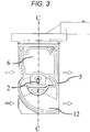
- FIG. 3 is a plan view of the thermal air flow meter that has been sealed by a filling material 6.
- FIG. 4 is a cross-sectional view taken along line C-C in FIG. 3 .
- the filling material 6 is applied to a space formed by the sensor assembly 10 and the housing 5 so as to cover the electronic component 3.
- An epoxy resin for example, is used as the filling material.
- the thermal air flow meter is applied to flow rate measurement in, for example, a vehicle in which an internal combustion engine is mounted, so that the thermal air flow meter is exposed to an environment containing, for example, exhaust gases, gasoline, and salt water.
- the covering of the electronic component 3 mounted on the sensor assembly 10 with the filling material 6 prevents the electronic component 3 from being exposed to the above environment, so that variations in characteristics of the electronic component 3 can be prevented and a thermal air flow meter offering even higher accuracy can be provided.
- FIG. 5 is a cross-sectional view of a thermal air flow meter that is subjected to a change in temperature.
- a thermal air flow meter that is subjected to a change in temperature.
- bending deformation as shown in FIG. 5 occurs in the thermal air flow meter and a substrate 1, as caused by a difference in coefficient of linear expansion or in resin contraction between the substrate 1 and the filling material 6. This results in stress (distortion) occurring also in a resistor 7 inside the electronic component 3.
- FIG. 6 represents calculations, performed through stress analysis, of variations in a flow rate characteristic caused by thermal stress encountered by the resistor 7 in the electronic component 3 with respect to a ratio of Young's modulus of the filling material 6 to Young's modulus of the substrate 1 and a ratio of a coefficient of linear expansion of the filling material 6 to a coefficient of linear expansion of the substrate 1.
- FIG. 6 plots the relations, as calculated using stress analysis, between the ratio of the Young's modulus of the filling material 6 to the Young' s modulus of the substrate 1 and the ratio of the coefficient of linear expansion of the filling material 6 to the coefficient of linear expansion of the substrate 1 when the variations in the flow rate characteristic as caused by the thermal stress encountered by the resistor 7 are ⁇ 1.0%, ⁇ 1.5%, and ⁇ 2.0%.
- the ratios of the Young's modulus and the coefficient of linear expansion of the substrate 1 to the Young' s modulus and the coefficient of linear expansion of the filling material 6 are arranged to fall within a predetermined range indicated by a hatched portion in FIG. 6 .
- x be the ratio of the coefficient of linear expansion of the substrate 1 to the coefficient of linear expansion of the filling material 6
- y the ratio of the Young's modulus of the substrate 1 to the Young's modulus of the filling material 6; then, a relation of y ⁇ 0.4 ⁇ -0.9 holds.
- FIG. 7 is a plan view of a thermal air flow meter in which a sensor assembly 10 is fixed to a housing 5.
- FIG. 8 is a bottom view.
- a configuration of the third embodiment differs from the preceding embodiments in that, as shown in FIGS. 7 and 8 , a plurality of electronic components 13 to 16 are disposed on a substrate. Examples of the electronic components include, but are not limited to, a thermistor, a microprocessor, a pressure sensor, and a humidity sensor.
- a bonding wire 20 is used to electrically connect the sensor assembly 10 with a connector 21 disposed in the housing.
- FIG. 9 is a plan view of the thermal air flow meter that has been sealed by a filling material 6. Understandably, the configuration shown in FIG. 9 achieves equivalent effects. Furthermore, protection provided for the bonding wire 20 by the filling material 6 can prevent the bonding wire 20 from being deformed from vibration, so that a highly reliable flow meter can be provided.
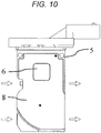
- a fourth embodiment of the present invention will be described below with reference to FIG. 10 .
- a configuration of the fourth embodiment differs from the preceding embodiments in that a cover 8 is disposed on a housing 5 for forming a sub-passage and the cover 8 has a hole formed in at least part thereof.
- a cover 8 is disposed on a housing 5 for forming a sub-passage and the cover 8 has a hole formed in at least part thereof.
- a fifth embodiment of the present invention will be described below with reference to FIG. 11 .
- the fifth embodiment differs from the preceding embodiments in that, as shown in FIG. 11 , the relation between the ratios of the Young's modulus and the coefficient of linear expansion of the substrate 1 included in the thermal air flow meter to the Young's modulus and the coefficient of linear expansion of the filling material 6 included in the thermal air flow meter falls within a range indicated by the hatched portion in FIG. 11 .
- y be the ratio of the Young's modulus of the substrate 1 to the Young's modulus of the filling material 6; then, a relation of y ⁇ 0.1 holds.
- the electronic components 3, and 13 to 16 shown in FIGS. 7 and 8 are electrically connected with a substrate 1 using a solder or a bonding wire.
- the substrate 1 and a connector 21 disposed in a housing are electrically connected with each other using the bonding wire 20.
- the difference in coefficient of linear expansion between these bonding materials and the filling material 6 is minimized. Having the relation within the range indicated by the hatched portion in FIG. 11 enables variations in the resistance value to be held within ⁇ 1% regardless of the ratio of the coefficient of linear expansion of the substrate 1 to the coefficient of linear expansion of the filling material 6. The difference in the coefficient of linear expansion between the solder or bonding wire and the filling material can thus be minimized and variations in the resistance value can be held within ⁇ 1%, so that a highly reliable flow meter offering high accuracy can be provided.
Landscapes
- Physics & Mathematics (AREA)
- Fluid Mechanics (AREA)
- General Physics & Mathematics (AREA)
- Engineering & Computer Science (AREA)
- Chemical & Material Sciences (AREA)
- Analytical Chemistry (AREA)
- Combustion & Propulsion (AREA)
- Mechanical Engineering (AREA)
- General Engineering & Computer Science (AREA)
- Measuring Volume Flow (AREA)
Applications Claiming Priority (2)
| Application Number | Priority Date | Filing Date | Title |
|---|---|---|---|
| JP2014225706A JP2016090413A (ja) | 2014-11-06 | 2014-11-06 | 熱式空気流量計 |
| PCT/JP2015/076833 WO2016072166A1 (fr) | 2014-11-06 | 2015-09-24 | Débitmètre d'air thermique |
Publications (3)
| Publication Number | Publication Date |
|---|---|
| EP3217153A1 true EP3217153A1 (fr) | 2017-09-13 |
| EP3217153A4 EP3217153A4 (fr) | 2018-08-29 |
| EP3217153B1 EP3217153B1 (fr) | 2022-03-23 |
Family
ID=55908895
Family Applications (1)
| Application Number | Title | Priority Date | Filing Date |
|---|---|---|---|
| EP15856909.5A Active EP3217153B1 (fr) | 2014-11-06 | 2015-09-24 | Débitmètre d'air thermique |
Country Status (5)
| Country | Link |
|---|---|
| US (1) | US10928232B2 (fr) |
| EP (1) | EP3217153B1 (fr) |
| JP (1) | JP2016090413A (fr) |
| CN (1) | CN107076593A (fr) |
| WO (1) | WO2016072166A1 (fr) |
Families Citing this family (6)
| Publication number | Priority date | Publication date | Assignee | Title |
|---|---|---|---|---|
| EP3358314B1 (fr) | 2015-09-30 | 2021-05-12 | Hitachi Automotive Systems, Ltd. | Dispositif de détection de quantité physique |
| JP6760253B2 (ja) * | 2017-07-24 | 2020-09-23 | 株式会社デンソー | 物理量計測装置及び物理量計測装置の製造方法 |
| JP6793107B2 (ja) * | 2017-11-27 | 2020-12-02 | 日立オートモティブシステムズ株式会社 | 流量計 |
| JP6838227B2 (ja) * | 2018-03-09 | 2021-03-03 | 日立Astemo株式会社 | 物理量測定装置 |
| JP7067531B2 (ja) | 2019-06-05 | 2022-05-16 | 株式会社デンソー | 空気流量測定装置 |
| WO2022254803A1 (fr) * | 2021-06-02 | 2022-12-08 | 日立Astemo株式会社 | Dispositif de détection de grandeur physique |
Family Cites Families (48)
| Publication number | Priority date | Publication date | Assignee | Title |
|---|---|---|---|---|
| JPS6045806B2 (ja) | 1979-08-22 | 1985-10-12 | 株式会社日立製作所 | 発熱抵抗体を用いた空気流量計 |
| JPS62152198A (ja) | 1985-12-26 | 1987-07-07 | 松下電器産業株式会社 | ハイブリツドic |
| JP2948040B2 (ja) | 1993-01-12 | 1999-09-13 | 株式会社日立製作所 | 発熱抵抗式空気流量計 |
| JP3396963B2 (ja) | 1994-08-25 | 2003-04-14 | 日産自動車株式会社 | 内燃機関の吸入空気量センサ |
| JP2790130B2 (ja) | 1996-07-22 | 1998-08-27 | 株式会社日立製作所 | エンジンルーム内に設置される電子機器 |
| JP3323745B2 (ja) | 1996-07-25 | 2002-09-09 | 株式会社日立製作所 | 物理量検出装置の特性調整手段および発熱抵抗式空気流量装置 |
| DE19741031A1 (de) | 1997-09-18 | 1999-03-25 | Bosch Gmbh Robert | Vorrichtung zur Messung der Masse eines strömenden Mediums |
| JP3336240B2 (ja) * | 1997-11-28 | 2002-10-21 | 京セラ株式会社 | 半導体素子実装基板 |
| JP2000046608A (ja) | 1998-07-29 | 2000-02-18 | Mitsui Mining & Smelting Co Ltd | 流量センサー |
| DE19927818C2 (de) | 1999-06-18 | 2003-10-23 | Bosch Gmbh Robert | Vorrichtung zur Messung der Masse eines strömenden Mediums |
| JP2001015649A (ja) * | 1999-06-29 | 2001-01-19 | Kyocera Corp | 半導体素子実装用配線基板および配線基板実装構造 |
| JP3587734B2 (ja) | 1999-06-30 | 2004-11-10 | 株式会社日立製作所 | 熱式空気流量センサ |
| JP2001244376A (ja) | 2000-02-28 | 2001-09-07 | Hitachi Ltd | 半導体装置 |
| US6516785B1 (en) | 2000-07-27 | 2003-02-11 | Hitachi, Ltd. | Air flow sensor |
| JP2002318147A (ja) | 2001-04-20 | 2002-10-31 | Denso Corp | 空気流量測定装置 |
| JP4196546B2 (ja) | 2001-04-23 | 2008-12-17 | 株式会社デンソー | 空気流量測定装置 |
| JP2003270016A (ja) | 2002-03-18 | 2003-09-25 | Hitachi Ltd | 流量計測装置 |
| DE10217883B4 (de) | 2002-04-22 | 2006-01-12 | Siemens Ag | Vorrichtung zur Messung einer Luftmasse im Ansaugtrakt einer Brennkraftmaschine |
| JP2004028631A (ja) * | 2002-06-21 | 2004-01-29 | Mitsubishi Electric Corp | 流量センサ |
| US6752015B2 (en) | 2002-09-24 | 2004-06-22 | Visteon Global Technologies, Inc. | Fluid flow device having reduced fluid ingress |
| JP4020208B2 (ja) | 2004-11-30 | 2007-12-12 | 三菱電機株式会社 | 流量測定装置 |
| US8130511B2 (en) * | 2006-05-22 | 2012-03-06 | Nec Corporation | Circuit board device, wiring board connecting method, and circuit board module device |
| JP2008182126A (ja) | 2007-01-25 | 2008-08-07 | Hitachi Ltd | エンジンルーム内に設置される電子機器 |
| JP2009031067A (ja) | 2007-07-25 | 2009-02-12 | Denso Corp | センサ装置 |
| DE102008037206B4 (de) | 2008-08-11 | 2014-07-03 | Heraeus Sensor Technology Gmbh | 300°C-Flowsensor |
| JP5125978B2 (ja) | 2008-10-16 | 2013-01-23 | 株式会社デンソー | センサ装置 |
| JP5168091B2 (ja) | 2008-11-05 | 2013-03-21 | 株式会社デンソー | 熱式フローセンサの製造方法及び熱式フローセンサ |
| JP2010133829A (ja) | 2008-12-04 | 2010-06-17 | Denso Corp | 熱式フローセンサ |
| JP5293278B2 (ja) * | 2009-03-05 | 2013-09-18 | 株式会社デンソー | 熱式流量計 |
| JP2011017491A (ja) | 2009-07-09 | 2011-01-27 | Panasonic Corp | 空気調和機 |
| JP5318737B2 (ja) | 2009-12-04 | 2013-10-16 | 株式会社デンソー | センサ装置およびその製造方法 |
| JP5208099B2 (ja) * | 2009-12-11 | 2013-06-12 | 日立オートモティブシステムズ株式会社 | 流量センサとその製造方法、及び流量センサモジュール |
| JP2011174910A (ja) | 2010-01-26 | 2011-09-08 | Panasonic Electric Works Co Ltd | 傾斜検知ユニット |
| JP5195819B2 (ja) | 2010-06-02 | 2013-05-15 | 株式会社デンソー | 空気流量測定装置 |
| JP2012015222A (ja) | 2010-06-30 | 2012-01-19 | Hitachi Ltd | 半導体装置 |
| JP5183683B2 (ja) * | 2010-07-02 | 2013-04-17 | 三菱電機株式会社 | 流量測定装置 |
| JP5445384B2 (ja) | 2010-08-02 | 2014-03-19 | 株式会社デンソー | 空気流量測定装置 |
| WO2012049742A1 (fr) | 2010-10-13 | 2012-04-19 | 日立オートモティブシステムズ株式会社 | Capteur d'écoulement et son procédé de production, et module de capteur d'écoulement et son procédé de production |
| CN102162774B (zh) | 2010-12-28 | 2013-09-11 | 北京中铁房山桥梁有限公司 | 钢结构分配梁式双线整孔箱梁静载试验装置及其施工方法 |
| JP5492834B2 (ja) | 2011-07-26 | 2014-05-14 | 日立オートモティブシステムズ株式会社 | 熱式流量計 |
| JP5870748B2 (ja) | 2012-02-22 | 2016-03-01 | 株式会社デンソー | 流量センサ |
| CN104364615B (zh) | 2012-06-15 | 2017-04-05 | 日立汽车系统株式会社 | 热式流量计 |
| JP2014001976A (ja) | 2012-06-15 | 2014-01-09 | Hitachi Automotive Systems Ltd | 熱式流量計 |
| JP2014102219A (ja) | 2012-11-22 | 2014-06-05 | Denso Corp | 流量センサ |
| JP5904959B2 (ja) | 2013-03-08 | 2016-04-20 | 日立オートモティブシステムズ株式会社 | 熱式空気流量計 |
| JP6013983B2 (ja) | 2013-06-20 | 2016-10-25 | 日立オートモティブシステムズ株式会社 | 物理量測定装置 |
| JP6043248B2 (ja) | 2013-07-24 | 2016-12-14 | 日立オートモティブシステムズ株式会社 | 熱式空気流量計 |
| EP3203195B1 (fr) | 2014-09-30 | 2021-12-08 | Hitachi Astemo, Ltd. | Débitmètre thermique |
-
2014
- 2014-11-06 JP JP2014225706A patent/JP2016090413A/ja active Pending
-
2015
- 2015-09-24 WO PCT/JP2015/076833 patent/WO2016072166A1/fr not_active Ceased
- 2015-09-24 EP EP15856909.5A patent/EP3217153B1/fr active Active
- 2015-09-24 US US15/519,452 patent/US10928232B2/en active Active
- 2015-09-24 CN CN201580057740.1A patent/CN107076593A/zh active Pending
Also Published As
| Publication number | Publication date |
|---|---|
| US20170241820A1 (en) | 2017-08-24 |
| JP2016090413A (ja) | 2016-05-23 |
| WO2016072166A1 (fr) | 2016-05-12 |
| EP3217153A4 (fr) | 2018-08-29 |
| EP3217153B1 (fr) | 2022-03-23 |
| CN107076593A (zh) | 2017-08-18 |
| US10928232B2 (en) | 2021-02-23 |
Similar Documents
| Publication | Publication Date | Title |
|---|---|---|
| US10928232B2 (en) | Thermal air flow meter | |
| JP5271997B2 (ja) | 吸気温度センサ | |
| EP2482050B1 (fr) | Capteur de température d'air d'admission et débitmètre d'air thermique l'incluant | |
| US7216546B2 (en) | Pressure sensor having integrated temperature sensor | |
| CN110672171B (zh) | 具有配置在副通路的流量检测元件的流量测定装置 | |
| CN103988056B (zh) | 热式流量计 | |
| CN111033186B (zh) | 热式流量计 | |
| US20140341255A1 (en) | Device for measuring a pressure and a temperature of a fluid medium flowing in a duct | |
| US8347707B2 (en) | Flow rate measuring apparatus | |
| US20110259097A1 (en) | Device for detecting a property of a flowing fluid medium | |
| JP6043833B2 (ja) | 熱式流量計 | |
| CN105008868B (zh) | 热式空气流量计 | |
| US12467796B2 (en) | Thermal probe assembly | |
| JP2016166895A (ja) | 熱式流量計 | |
| JP2020079808A (ja) | 熱式空気流量計 | |
| EP3064906A1 (fr) | Dispositif de mesure d'écoulement d'air | |
| CN220794505U (zh) | 传感器 | |
| JP5092887B2 (ja) | 濃度検出装置 | |
| JP2021032845A (ja) | センサ装置 | |
| JP2020079710A (ja) | 温度検出機能付き圧力検出装置 |
Legal Events
| Date | Code | Title | Description |
|---|---|---|---|
| STAA | Information on the status of an ep patent application or granted ep patent |
Free format text: STATUS: THE INTERNATIONAL PUBLICATION HAS BEEN MADE |
|
| PUAI | Public reference made under article 153(3) epc to a published international application that has entered the european phase |
Free format text: ORIGINAL CODE: 0009012 |
|
| STAA | Information on the status of an ep patent application or granted ep patent |
Free format text: STATUS: REQUEST FOR EXAMINATION WAS MADE |
|
| 17P | Request for examination filed |
Effective date: 20170606 |
|
| AK | Designated contracting states |
Kind code of ref document: A1 Designated state(s): AL AT BE BG CH CY CZ DE DK EE ES FI FR GB GR HR HU IE IS IT LI LT LU LV MC MK MT NL NO PL PT RO RS SE SI SK SM TR |
|
| AX | Request for extension of the european patent |
Extension state: BA ME |
|
| DAV | Request for validation of the european patent (deleted) | ||
| DAX | Request for extension of the european patent (deleted) | ||
| TPAC | Observations filed by third parties |
Free format text: ORIGINAL CODE: EPIDOSNTIPA |
|
| TPAC | Observations filed by third parties |
Free format text: ORIGINAL CODE: EPIDOSNTIPA |
|
| TPAC | Observations filed by third parties |
Free format text: ORIGINAL CODE: EPIDOSNTIPA |
|
| TPAC | Observations filed by third parties |
Free format text: ORIGINAL CODE: EPIDOSNTIPA |
|
| A4 | Supplementary search report drawn up and despatched |
Effective date: 20180801 |
|
| RIC1 | Information provided on ipc code assigned before grant |
Ipc: G01F 1/684 20060101AFI20180726BHEP Ipc: G01F 1/696 20060101ALI20180726BHEP Ipc: F02M 35/10 20060101ALI20180726BHEP Ipc: G01F 15/00 20060101ALI20180726BHEP |
|
| TPAC | Observations filed by third parties |
Free format text: ORIGINAL CODE: EPIDOSNTIPA |
|
| TPAC | Observations filed by third parties |
Free format text: ORIGINAL CODE: EPIDOSNTIPA |
|
| TPAC | Observations filed by third parties |
Free format text: ORIGINAL CODE: EPIDOSNTIPA |
|
| TPAC | Observations filed by third parties |
Free format text: ORIGINAL CODE: EPIDOSNTIPA |
|
| TPAC | Observations filed by third parties |
Free format text: ORIGINAL CODE: EPIDOSNTIPA |
|
| TPAC | Observations filed by third parties |
Free format text: ORIGINAL CODE: EPIDOSNTIPA |
|
| TPAC | Observations filed by third parties |
Free format text: ORIGINAL CODE: EPIDOSNTIPA |
|
| TPAC | Observations filed by third parties |
Free format text: ORIGINAL CODE: EPIDOSNTIPA |
|
| RAP3 | Party data changed (applicant data changed or rights of an application transferred) |
Owner name: HITACHI ASTEMO, LTD. |
|
| RIC1 | Information provided on ipc code assigned before grant |
Ipc: G01F 15/02 20060101ALI20211102BHEP Ipc: G01F 15/00 20060101ALI20211102BHEP Ipc: G01F 1/696 20060101ALI20211102BHEP Ipc: F02M 35/10 20060101ALI20211102BHEP Ipc: G01F 1/684 20060101AFI20211102BHEP |
|
| GRAP | Despatch of communication of intention to grant a patent |
Free format text: ORIGINAL CODE: EPIDOSNIGR1 |
|
| STAA | Information on the status of an ep patent application or granted ep patent |
Free format text: STATUS: GRANT OF PATENT IS INTENDED |
|
| INTG | Intention to grant announced |
Effective date: 20220107 |
|
| RIN1 | Information on inventor provided before grant (corrected) |
Inventor name: HOSHIKA, HIROAKI Inventor name: YOGO, TAKAYUKI Inventor name: ISHITSUKA, NORIO Inventor name: OGATA, MASATOSHI |
|
| GRAS | Grant fee paid |
Free format text: ORIGINAL CODE: EPIDOSNIGR3 |
|
| GRAA | (expected) grant |
Free format text: ORIGINAL CODE: 0009210 |
|
| STAA | Information on the status of an ep patent application or granted ep patent |
Free format text: STATUS: THE PATENT HAS BEEN GRANTED |
|
| AK | Designated contracting states |
Kind code of ref document: B1 Designated state(s): AL AT BE BG CH CY CZ DE DK EE ES FI FR GB GR HR HU IE IS IT LI LT LU LV MC MK MT NL NO PL PT RO RS SE SI SK SM TR |
|
| REG | Reference to a national code |
Ref country code: GB Ref legal event code: FG4D |
|
| REG | Reference to a national code |
Ref country code: CH Ref legal event code: EP |
|
| REG | Reference to a national code |
Ref country code: IE Ref legal event code: FG4D |
|
| REG | Reference to a national code |
Ref country code: DE Ref legal event code: R096 Ref document number: 602015077766 Country of ref document: DE |
|
| REG | Reference to a national code |
Ref country code: AT Ref legal event code: REF Ref document number: 1477741 Country of ref document: AT Kind code of ref document: T Effective date: 20220415 |
|
| REG | Reference to a national code |
Ref country code: LT Ref legal event code: MG9D |
|
| REG | Reference to a national code |
Ref country code: NL Ref legal event code: MP Effective date: 20220323 |
|
| PG25 | Lapsed in a contracting state [announced via postgrant information from national office to epo] |
Ref country code: SE Free format text: LAPSE BECAUSE OF FAILURE TO SUBMIT A TRANSLATION OF THE DESCRIPTION OR TO PAY THE FEE WITHIN THE PRESCRIBED TIME-LIMIT Effective date: 20220323 Ref country code: RS Free format text: LAPSE BECAUSE OF FAILURE TO SUBMIT A TRANSLATION OF THE DESCRIPTION OR TO PAY THE FEE WITHIN THE PRESCRIBED TIME-LIMIT Effective date: 20220323 Ref country code: NO Free format text: LAPSE BECAUSE OF FAILURE TO SUBMIT A TRANSLATION OF THE DESCRIPTION OR TO PAY THE FEE WITHIN THE PRESCRIBED TIME-LIMIT Effective date: 20220623 Ref country code: LT Free format text: LAPSE BECAUSE OF FAILURE TO SUBMIT A TRANSLATION OF THE DESCRIPTION OR TO PAY THE FEE WITHIN THE PRESCRIBED TIME-LIMIT Effective date: 20220323 Ref country code: HR Free format text: LAPSE BECAUSE OF FAILURE TO SUBMIT A TRANSLATION OF THE DESCRIPTION OR TO PAY THE FEE WITHIN THE PRESCRIBED TIME-LIMIT Effective date: 20220323 Ref country code: BG Free format text: LAPSE BECAUSE OF FAILURE TO SUBMIT A TRANSLATION OF THE DESCRIPTION OR TO PAY THE FEE WITHIN THE PRESCRIBED TIME-LIMIT Effective date: 20220623 |
|
| REG | Reference to a national code |
Ref country code: AT Ref legal event code: MK05 Ref document number: 1477741 Country of ref document: AT Kind code of ref document: T Effective date: 20220323 |
|
| PG25 | Lapsed in a contracting state [announced via postgrant information from national office to epo] |
Ref country code: LV Free format text: LAPSE BECAUSE OF FAILURE TO SUBMIT A TRANSLATION OF THE DESCRIPTION OR TO PAY THE FEE WITHIN THE PRESCRIBED TIME-LIMIT Effective date: 20220323 Ref country code: GR Free format text: LAPSE BECAUSE OF FAILURE TO SUBMIT A TRANSLATION OF THE DESCRIPTION OR TO PAY THE FEE WITHIN THE PRESCRIBED TIME-LIMIT Effective date: 20220624 Ref country code: FI Free format text: LAPSE BECAUSE OF FAILURE TO SUBMIT A TRANSLATION OF THE DESCRIPTION OR TO PAY THE FEE WITHIN THE PRESCRIBED TIME-LIMIT Effective date: 20220323 |
|
| PG25 | Lapsed in a contracting state [announced via postgrant information from national office to epo] |
Ref country code: NL Free format text: LAPSE BECAUSE OF FAILURE TO SUBMIT A TRANSLATION OF THE DESCRIPTION OR TO PAY THE FEE WITHIN THE PRESCRIBED TIME-LIMIT Effective date: 20220323 |
|
| PG25 | Lapsed in a contracting state [announced via postgrant information from national office to epo] |
Ref country code: SM Free format text: LAPSE BECAUSE OF FAILURE TO SUBMIT A TRANSLATION OF THE DESCRIPTION OR TO PAY THE FEE WITHIN THE PRESCRIBED TIME-LIMIT Effective date: 20220323 Ref country code: SK Free format text: LAPSE BECAUSE OF FAILURE TO SUBMIT A TRANSLATION OF THE DESCRIPTION OR TO PAY THE FEE WITHIN THE PRESCRIBED TIME-LIMIT Effective date: 20220323 Ref country code: RO Free format text: LAPSE BECAUSE OF FAILURE TO SUBMIT A TRANSLATION OF THE DESCRIPTION OR TO PAY THE FEE WITHIN THE PRESCRIBED TIME-LIMIT Effective date: 20220323 Ref country code: PT Free format text: LAPSE BECAUSE OF FAILURE TO SUBMIT A TRANSLATION OF THE DESCRIPTION OR TO PAY THE FEE WITHIN THE PRESCRIBED TIME-LIMIT Effective date: 20220725 Ref country code: ES Free format text: LAPSE BECAUSE OF FAILURE TO SUBMIT A TRANSLATION OF THE DESCRIPTION OR TO PAY THE FEE WITHIN THE PRESCRIBED TIME-LIMIT Effective date: 20220323 Ref country code: EE Free format text: LAPSE BECAUSE OF FAILURE TO SUBMIT A TRANSLATION OF THE DESCRIPTION OR TO PAY THE FEE WITHIN THE PRESCRIBED TIME-LIMIT Effective date: 20220323 Ref country code: CZ Free format text: LAPSE BECAUSE OF FAILURE TO SUBMIT A TRANSLATION OF THE DESCRIPTION OR TO PAY THE FEE WITHIN THE PRESCRIBED TIME-LIMIT Effective date: 20220323 Ref country code: AT Free format text: LAPSE BECAUSE OF FAILURE TO SUBMIT A TRANSLATION OF THE DESCRIPTION OR TO PAY THE FEE WITHIN THE PRESCRIBED TIME-LIMIT Effective date: 20220323 |
|
| PG25 | Lapsed in a contracting state [announced via postgrant information from national office to epo] |
Ref country code: PL Free format text: LAPSE BECAUSE OF FAILURE TO SUBMIT A TRANSLATION OF THE DESCRIPTION OR TO PAY THE FEE WITHIN THE PRESCRIBED TIME-LIMIT Effective date: 20220323 Ref country code: IS Free format text: LAPSE BECAUSE OF FAILURE TO SUBMIT A TRANSLATION OF THE DESCRIPTION OR TO PAY THE FEE WITHIN THE PRESCRIBED TIME-LIMIT Effective date: 20220723 Ref country code: AL Free format text: LAPSE BECAUSE OF FAILURE TO SUBMIT A TRANSLATION OF THE DESCRIPTION OR TO PAY THE FEE WITHIN THE PRESCRIBED TIME-LIMIT Effective date: 20220323 |
|
| REG | Reference to a national code |
Ref country code: DE Ref legal event code: R097 Ref document number: 602015077766 Country of ref document: DE |
|
| PLBE | No opposition filed within time limit |
Free format text: ORIGINAL CODE: 0009261 |
|
| STAA | Information on the status of an ep patent application or granted ep patent |
Free format text: STATUS: NO OPPOSITION FILED WITHIN TIME LIMIT |
|
| PG25 | Lapsed in a contracting state [announced via postgrant information from national office to epo] |
Ref country code: DK Free format text: LAPSE BECAUSE OF FAILURE TO SUBMIT A TRANSLATION OF THE DESCRIPTION OR TO PAY THE FEE WITHIN THE PRESCRIBED TIME-LIMIT Effective date: 20220323 |
|
| 26N | No opposition filed |
Effective date: 20230102 |
|
| PG25 | Lapsed in a contracting state [announced via postgrant information from national office to epo] |
Ref country code: MC Free format text: LAPSE BECAUSE OF FAILURE TO SUBMIT A TRANSLATION OF THE DESCRIPTION OR TO PAY THE FEE WITHIN THE PRESCRIBED TIME-LIMIT Effective date: 20220323 |
|
| REG | Reference to a national code |
Ref country code: CH Ref legal event code: PL |
|
| GBPC | Gb: european patent ceased through non-payment of renewal fee |
Effective date: 20220924 |
|
| REG | Reference to a national code |
Ref country code: BE Ref legal event code: MM Effective date: 20220930 |
|
| PG25 | Lapsed in a contracting state [announced via postgrant information from national office to epo] |
Ref country code: SI Free format text: LAPSE BECAUSE OF FAILURE TO SUBMIT A TRANSLATION OF THE DESCRIPTION OR TO PAY THE FEE WITHIN THE PRESCRIBED TIME-LIMIT Effective date: 20220323 |
|
| PG25 | Lapsed in a contracting state [announced via postgrant information from national office to epo] |
Ref country code: LU Free format text: LAPSE BECAUSE OF NON-PAYMENT OF DUE FEES Effective date: 20220924 |
|
| PG25 | Lapsed in a contracting state [announced via postgrant information from national office to epo] |
Ref country code: LI Free format text: LAPSE BECAUSE OF NON-PAYMENT OF DUE FEES Effective date: 20220930 Ref country code: IT Free format text: LAPSE BECAUSE OF FAILURE TO SUBMIT A TRANSLATION OF THE DESCRIPTION OR TO PAY THE FEE WITHIN THE PRESCRIBED TIME-LIMIT Effective date: 20220323 Ref country code: IE Free format text: LAPSE BECAUSE OF NON-PAYMENT OF DUE FEES Effective date: 20220924 Ref country code: FR Free format text: LAPSE BECAUSE OF NON-PAYMENT OF DUE FEES Effective date: 20220930 Ref country code: CH Free format text: LAPSE BECAUSE OF NON-PAYMENT OF DUE FEES Effective date: 20220930 |
|
| PG25 | Lapsed in a contracting state [announced via postgrant information from national office to epo] |
Ref country code: BE Free format text: LAPSE BECAUSE OF NON-PAYMENT OF DUE FEES Effective date: 20220930 |
|
| PG25 | Lapsed in a contracting state [announced via postgrant information from national office to epo] |
Ref country code: GB Free format text: LAPSE BECAUSE OF NON-PAYMENT OF DUE FEES Effective date: 20220924 |
|
| PG25 | Lapsed in a contracting state [announced via postgrant information from national office to epo] |
Ref country code: HU Free format text: LAPSE BECAUSE OF FAILURE TO SUBMIT A TRANSLATION OF THE DESCRIPTION OR TO PAY THE FEE WITHIN THE PRESCRIBED TIME-LIMIT; INVALID AB INITIO Effective date: 20150924 |
|
| PG25 | Lapsed in a contracting state [announced via postgrant information from national office to epo] |
Ref country code: CY Free format text: LAPSE BECAUSE OF FAILURE TO SUBMIT A TRANSLATION OF THE DESCRIPTION OR TO PAY THE FEE WITHIN THE PRESCRIBED TIME-LIMIT Effective date: 20220323 |
|
| PG25 | Lapsed in a contracting state [announced via postgrant information from national office to epo] |
Ref country code: MK Free format text: LAPSE BECAUSE OF FAILURE TO SUBMIT A TRANSLATION OF THE DESCRIPTION OR TO PAY THE FEE WITHIN THE PRESCRIBED TIME-LIMIT Effective date: 20220323 |
|
| PG25 | Lapsed in a contracting state [announced via postgrant information from national office to epo] |
Ref country code: TR Free format text: LAPSE BECAUSE OF FAILURE TO SUBMIT A TRANSLATION OF THE DESCRIPTION OR TO PAY THE FEE WITHIN THE PRESCRIBED TIME-LIMIT Effective date: 20220323 |
|
| PG25 | Lapsed in a contracting state [announced via postgrant information from national office to epo] |
Ref country code: MT Free format text: LAPSE BECAUSE OF FAILURE TO SUBMIT A TRANSLATION OF THE DESCRIPTION OR TO PAY THE FEE WITHIN THE PRESCRIBED TIME-LIMIT Effective date: 20220323 |
|
| PGFP | Annual fee paid to national office [announced via postgrant information from national office to epo] |
Ref country code: DE Payment date: 20250730 Year of fee payment: 11 |