EP3207977B1 - Abgasreinigungsvorrichtung - Google Patents
Abgasreinigungsvorrichtung Download PDFInfo
- Publication number
- EP3207977B1 EP3207977B1 EP15850326.8A EP15850326A EP3207977B1 EP 3207977 B1 EP3207977 B1 EP 3207977B1 EP 15850326 A EP15850326 A EP 15850326A EP 3207977 B1 EP3207977 B1 EP 3207977B1
- Authority
- EP
- European Patent Office
- Prior art keywords
- exhaust gas
- catalyst region
- partition
- catalyst
- purification apparatus
- Prior art date
- Legal status (The legal status is an assumption and is not a legal conclusion. Google has not performed a legal analysis and makes no representation as to the accuracy of the status listed.)
- Active
Links
Images

Classifications
-
- B—PERFORMING OPERATIONS; TRANSPORTING
- B01—PHYSICAL OR CHEMICAL PROCESSES OR APPARATUS IN GENERAL
- B01J—CHEMICAL OR PHYSICAL PROCESSES, e.g. CATALYSIS OR COLLOID CHEMISTRY; THEIR RELEVANT APPARATUS
- B01J23/00—Catalysts comprising metals or metal oxides or hydroxides, not provided for in group B01J21/00
- B01J23/38—Catalysts comprising metals or metal oxides or hydroxides, not provided for in group B01J21/00 of noble metals
- B01J23/54—Catalysts comprising metals or metal oxides or hydroxides, not provided for in group B01J21/00 of noble metals combined with metals, oxides or hydroxides provided for in groups B01J23/02 - B01J23/36
- B01J23/56—Platinum group metals
- B01J23/63—Platinum group metals with rare earths or actinides
-
- B—PERFORMING OPERATIONS; TRANSPORTING
- B01—PHYSICAL OR CHEMICAL PROCESSES OR APPARATUS IN GENERAL
- B01D—SEPARATION
- B01D53/00—Separation of gases or vapours; Recovering vapours of volatile solvents from gases; Chemical or biological purification of waste gases, e.g. engine exhaust gases, smoke, fumes, flue gases, aerosols
- B01D53/34—Chemical or biological purification of waste gases
- B01D53/92—Chemical or biological purification of waste gases of engine exhaust gases
- B01D53/94—Chemical or biological purification of waste gases of engine exhaust gases by catalytic processes
- B01D53/9445—Simultaneously removing carbon monoxide, hydrocarbons or nitrogen oxides making use of three-way catalysts [TWC] or four-way-catalysts [FWC]
- B01D53/945—Simultaneously removing carbon monoxide, hydrocarbons or nitrogen oxides making use of three-way catalysts [TWC] or four-way-catalysts [FWC] characterised by a specific catalyst
-
- B—PERFORMING OPERATIONS; TRANSPORTING
- B01—PHYSICAL OR CHEMICAL PROCESSES OR APPARATUS IN GENERAL
- B01D—SEPARATION
- B01D53/00—Separation of gases or vapours; Recovering vapours of volatile solvents from gases; Chemical or biological purification of waste gases, e.g. engine exhaust gases, smoke, fumes, flue gases, aerosols
- B01D53/34—Chemical or biological purification of waste gases
- B01D53/92—Chemical or biological purification of waste gases of engine exhaust gases
- B01D53/94—Chemical or biological purification of waste gases of engine exhaust gases by catalytic processes
- B01D53/9445—Simultaneously removing carbon monoxide, hydrocarbons or nitrogen oxides making use of three-way catalysts [TWC] or four-way-catalysts [FWC]
- B01D53/9454—Simultaneously removing carbon monoxide, hydrocarbons or nitrogen oxides making use of three-way catalysts [TWC] or four-way-catalysts [FWC] characterised by a specific device
-
- B—PERFORMING OPERATIONS; TRANSPORTING
- B01—PHYSICAL OR CHEMICAL PROCESSES OR APPARATUS IN GENERAL
- B01J—CHEMICAL OR PHYSICAL PROCESSES, e.g. CATALYSIS OR COLLOID CHEMISTRY; THEIR RELEVANT APPARATUS
- B01J21/00—Catalysts comprising the elements, oxides, or hydroxides of magnesium, boron, aluminium, carbon, silicon, titanium, zirconium, or hafnium
- B01J21/02—Boron or aluminium; Oxides or hydroxides thereof
- B01J21/04—Alumina
-
- B—PERFORMING OPERATIONS; TRANSPORTING
- B01—PHYSICAL OR CHEMICAL PROCESSES OR APPARATUS IN GENERAL
- B01J—CHEMICAL OR PHYSICAL PROCESSES, e.g. CATALYSIS OR COLLOID CHEMISTRY; THEIR RELEVANT APPARATUS
- B01J21/00—Catalysts comprising the elements, oxides, or hydroxides of magnesium, boron, aluminium, carbon, silicon, titanium, zirconium, or hafnium
- B01J21/06—Silicon, titanium, zirconium or hafnium; Oxides or hydroxides thereof
- B01J21/066—Zirconium or hafnium; Oxides or hydroxides thereof
-
- B—PERFORMING OPERATIONS; TRANSPORTING
- B01—PHYSICAL OR CHEMICAL PROCESSES OR APPARATUS IN GENERAL
- B01J—CHEMICAL OR PHYSICAL PROCESSES, e.g. CATALYSIS OR COLLOID CHEMISTRY; THEIR RELEVANT APPARATUS
- B01J23/00—Catalysts comprising metals or metal oxides or hydroxides, not provided for in group B01J21/00
- B01J23/38—Catalysts comprising metals or metal oxides or hydroxides, not provided for in group B01J21/00 of noble metals
- B01J23/40—Catalysts comprising metals or metal oxides or hydroxides, not provided for in group B01J21/00 of noble metals of the platinum group metals
- B01J23/46—Ruthenium, rhodium, osmium or iridium
- B01J23/464—Rhodium
-
- B—PERFORMING OPERATIONS; TRANSPORTING
- B01—PHYSICAL OR CHEMICAL PROCESSES OR APPARATUS IN GENERAL
- B01J—CHEMICAL OR PHYSICAL PROCESSES, e.g. CATALYSIS OR COLLOID CHEMISTRY; THEIR RELEVANT APPARATUS
- B01J35/00—Catalysts, in general, characterised by their form or physical properties
- B01J35/19—Catalysts containing parts with different compositions
-
- B—PERFORMING OPERATIONS; TRANSPORTING
- B01—PHYSICAL OR CHEMICAL PROCESSES OR APPARATUS IN GENERAL
- B01J—CHEMICAL OR PHYSICAL PROCESSES, e.g. CATALYSIS OR COLLOID CHEMISTRY; THEIR RELEVANT APPARATUS
- B01J35/00—Catalysts, in general, characterised by their form or physical properties
- B01J35/50—Catalysts, in general, characterised by their form or physical properties characterised by their shape or configuration
- B01J35/56—Foraminous structures having flow-through passages or channels, e.g. grids or three-dimensional monoliths
-
- B—PERFORMING OPERATIONS; TRANSPORTING
- B01—PHYSICAL OR CHEMICAL PROCESSES OR APPARATUS IN GENERAL
- B01J—CHEMICAL OR PHYSICAL PROCESSES, e.g. CATALYSIS OR COLLOID CHEMISTRY; THEIR RELEVANT APPARATUS
- B01J35/00—Catalysts, in general, characterised by their form or physical properties
- B01J35/60—Catalysts, in general, characterised by their form or physical properties characterised by their surface properties or porosity
- B01J35/64—Pore diameter
- B01J35/657—Pore diameter larger than 1000 nm
-
- B—PERFORMING OPERATIONS; TRANSPORTING
- B01—PHYSICAL OR CHEMICAL PROCESSES OR APPARATUS IN GENERAL
- B01J—CHEMICAL OR PHYSICAL PROCESSES, e.g. CATALYSIS OR COLLOID CHEMISTRY; THEIR RELEVANT APPARATUS
- B01J35/00—Catalysts, in general, characterised by their form or physical properties
- B01J35/60—Catalysts, in general, characterised by their form or physical properties characterised by their surface properties or porosity
- B01J35/66—Pore distribution
- B01J35/69—Pore distribution bimodal
-
- B—PERFORMING OPERATIONS; TRANSPORTING
- B01—PHYSICAL OR CHEMICAL PROCESSES OR APPARATUS IN GENERAL
- B01J—CHEMICAL OR PHYSICAL PROCESSES, e.g. CATALYSIS OR COLLOID CHEMISTRY; THEIR RELEVANT APPARATUS
- B01J37/00—Processes, in general, for preparing catalysts; Processes, in general, for activation of catalysts
- B01J37/02—Impregnation, coating or precipitation
- B01J37/0215—Coating
-
- B—PERFORMING OPERATIONS; TRANSPORTING
- B01—PHYSICAL OR CHEMICAL PROCESSES OR APPARATUS IN GENERAL
- B01J—CHEMICAL OR PHYSICAL PROCESSES, e.g. CATALYSIS OR COLLOID CHEMISTRY; THEIR RELEVANT APPARATUS
- B01J37/00—Processes, in general, for preparing catalysts; Processes, in general, for activation of catalysts
- B01J37/02—Impregnation, coating or precipitation
- B01J37/024—Multiple impregnation or coating
- B01J37/0244—Coatings comprising several layers
-
- B—PERFORMING OPERATIONS; TRANSPORTING
- B01—PHYSICAL OR CHEMICAL PROCESSES OR APPARATUS IN GENERAL
- B01J—CHEMICAL OR PHYSICAL PROCESSES, e.g. CATALYSIS OR COLLOID CHEMISTRY; THEIR RELEVANT APPARATUS
- B01J37/00—Processes, in general, for preparing catalysts; Processes, in general, for activation of catalysts
- B01J37/02—Impregnation, coating or precipitation
- B01J37/024—Multiple impregnation or coating
- B01J37/0248—Coatings comprising impregnated particles
-
- B—PERFORMING OPERATIONS; TRANSPORTING
- B01—PHYSICAL OR CHEMICAL PROCESSES OR APPARATUS IN GENERAL
- B01J—CHEMICAL OR PHYSICAL PROCESSES, e.g. CATALYSIS OR COLLOID CHEMISTRY; THEIR RELEVANT APPARATUS
- B01J37/00—Processes, in general, for preparing catalysts; Processes, in general, for activation of catalysts
- B01J37/02—Impregnation, coating or precipitation
- B01J37/03—Precipitation; Co-precipitation
- B01J37/038—Precipitation; Co-precipitation to form slurries or suspensions, e.g. a washcoat
-
- F—MECHANICAL ENGINEERING; LIGHTING; HEATING; WEAPONS; BLASTING
- F01—MACHINES OR ENGINES IN GENERAL; ENGINE PLANTS IN GENERAL; STEAM ENGINES
- F01N—GAS-FLOW SILENCERS OR EXHAUST APPARATUS FOR MACHINES OR ENGINES IN GENERAL; GAS-FLOW SILENCERS OR EXHAUST APPARATUS FOR INTERNAL-COMBUSTION ENGINES
- F01N3/00—Exhaust or silencing apparatus having means for purifying, rendering innocuous, or otherwise treating exhaust
- F01N3/02—Exhaust or silencing apparatus having means for purifying, rendering innocuous, or otherwise treating exhaust for cooling, or for removing solid constituents of, exhaust
- F01N3/021—Exhaust or silencing apparatus having means for purifying, rendering innocuous, or otherwise treating exhaust for cooling, or for removing solid constituents of, exhaust by means of filters
- F01N3/022—Exhaust or silencing apparatus having means for purifying, rendering innocuous, or otherwise treating exhaust for cooling, or for removing solid constituents of, exhaust by means of filters characterised by specially adapted filtering structure, e.g. honeycomb, mesh or fibrous
- F01N3/0222—Exhaust or silencing apparatus having means for purifying, rendering innocuous, or otherwise treating exhaust for cooling, or for removing solid constituents of, exhaust by means of filters characterised by specially adapted filtering structure, e.g. honeycomb, mesh or fibrous the structure being monolithic, e.g. honeycombs
-
- F—MECHANICAL ENGINEERING; LIGHTING; HEATING; WEAPONS; BLASTING
- F01—MACHINES OR ENGINES IN GENERAL; ENGINE PLANTS IN GENERAL; STEAM ENGINES
- F01N—GAS-FLOW SILENCERS OR EXHAUST APPARATUS FOR MACHINES OR ENGINES IN GENERAL; GAS-FLOW SILENCERS OR EXHAUST APPARATUS FOR INTERNAL-COMBUSTION ENGINES
- F01N3/00—Exhaust or silencing apparatus having means for purifying, rendering innocuous, or otherwise treating exhaust
- F01N3/02—Exhaust or silencing apparatus having means for purifying, rendering innocuous, or otherwise treating exhaust for cooling, or for removing solid constituents of, exhaust
- F01N3/021—Exhaust or silencing apparatus having means for purifying, rendering innocuous, or otherwise treating exhaust for cooling, or for removing solid constituents of, exhaust by means of filters
- F01N3/023—Exhaust or silencing apparatus having means for purifying, rendering innocuous, or otherwise treating exhaust for cooling, or for removing solid constituents of, exhaust by means of filters using means for regenerating the filters, e.g. by burning trapped particles
-
- F—MECHANICAL ENGINEERING; LIGHTING; HEATING; WEAPONS; BLASTING
- F01—MACHINES OR ENGINES IN GENERAL; ENGINE PLANTS IN GENERAL; STEAM ENGINES
- F01N—GAS-FLOW SILENCERS OR EXHAUST APPARATUS FOR MACHINES OR ENGINES IN GENERAL; GAS-FLOW SILENCERS OR EXHAUST APPARATUS FOR INTERNAL-COMBUSTION ENGINES
- F01N3/00—Exhaust or silencing apparatus having means for purifying, rendering innocuous, or otherwise treating exhaust
- F01N3/02—Exhaust or silencing apparatus having means for purifying, rendering innocuous, or otherwise treating exhaust for cooling, or for removing solid constituents of, exhaust
- F01N3/021—Exhaust or silencing apparatus having means for purifying, rendering innocuous, or otherwise treating exhaust for cooling, or for removing solid constituents of, exhaust by means of filters
- F01N3/033—Exhaust or silencing apparatus having means for purifying, rendering innocuous, or otherwise treating exhaust for cooling, or for removing solid constituents of, exhaust by means of filters in combination with other devices
- F01N3/035—Exhaust or silencing apparatus having means for purifying, rendering innocuous, or otherwise treating exhaust for cooling, or for removing solid constituents of, exhaust by means of filters in combination with other devices with catalytic reactors
-
- F—MECHANICAL ENGINEERING; LIGHTING; HEATING; WEAPONS; BLASTING
- F01—MACHINES OR ENGINES IN GENERAL; ENGINE PLANTS IN GENERAL; STEAM ENGINES
- F01N—GAS-FLOW SILENCERS OR EXHAUST APPARATUS FOR MACHINES OR ENGINES IN GENERAL; GAS-FLOW SILENCERS OR EXHAUST APPARATUS FOR INTERNAL-COMBUSTION ENGINES
- F01N3/00—Exhaust or silencing apparatus having means for purifying, rendering innocuous, or otherwise treating exhaust
- F01N3/08—Exhaust or silencing apparatus having means for purifying, rendering innocuous, or otherwise treating exhaust for rendering innocuous
- F01N3/0807—Exhaust or silencing apparatus having means for purifying, rendering innocuous, or otherwise treating exhaust for rendering innocuous by using absorbents or adsorbents
- F01N3/0828—Exhaust or silencing apparatus having means for purifying, rendering innocuous, or otherwise treating exhaust for rendering innocuous by using absorbents or adsorbents characterised by the absorbed or adsorbed substances
- F01N3/0842—Nitrogen oxides
-
- F—MECHANICAL ENGINEERING; LIGHTING; HEATING; WEAPONS; BLASTING
- F01—MACHINES OR ENGINES IN GENERAL; ENGINE PLANTS IN GENERAL; STEAM ENGINES
- F01N—GAS-FLOW SILENCERS OR EXHAUST APPARATUS FOR MACHINES OR ENGINES IN GENERAL; GAS-FLOW SILENCERS OR EXHAUST APPARATUS FOR INTERNAL-COMBUSTION ENGINES
- F01N3/00—Exhaust or silencing apparatus having means for purifying, rendering innocuous, or otherwise treating exhaust
- F01N3/08—Exhaust or silencing apparatus having means for purifying, rendering innocuous, or otherwise treating exhaust for rendering innocuous
- F01N3/0807—Exhaust or silencing apparatus having means for purifying, rendering innocuous, or otherwise treating exhaust for rendering innocuous by using absorbents or adsorbents
- F01N3/0828—Exhaust or silencing apparatus having means for purifying, rendering innocuous, or otherwise treating exhaust for rendering innocuous by using absorbents or adsorbents characterised by the absorbed or adsorbed substances
- F01N3/0864—Oxygen
-
- F—MECHANICAL ENGINEERING; LIGHTING; HEATING; WEAPONS; BLASTING
- F01—MACHINES OR ENGINES IN GENERAL; ENGINE PLANTS IN GENERAL; STEAM ENGINES
- F01N—GAS-FLOW SILENCERS OR EXHAUST APPARATUS FOR MACHINES OR ENGINES IN GENERAL; GAS-FLOW SILENCERS OR EXHAUST APPARATUS FOR INTERNAL-COMBUSTION ENGINES
- F01N3/00—Exhaust or silencing apparatus having means for purifying, rendering innocuous, or otherwise treating exhaust
- F01N3/08—Exhaust or silencing apparatus having means for purifying, rendering innocuous, or otherwise treating exhaust for rendering innocuous
- F01N3/10—Exhaust or silencing apparatus having means for purifying, rendering innocuous, or otherwise treating exhaust for rendering innocuous by thermal or catalytic conversion of noxious components of exhaust
- F01N3/24—Exhaust or silencing apparatus having means for purifying, rendering innocuous, or otherwise treating exhaust for rendering innocuous by thermal or catalytic conversion of noxious components of exhaust characterised by constructional aspects of converting apparatus
- F01N3/28—Construction of catalytic reactors
- F01N3/2839—Arrangements for mounting catalyst support in housing, e.g. with means for compensating thermal expansion or vibration
- F01N3/2878—Arrangements for mounting catalyst support in housing, e.g. with means for compensating thermal expansion or vibration by using non-elastic means for retaining catalyst body in the housing, e.g. a metal chamfer, or by corrugation or deformation of the metal housing
-
- B—PERFORMING OPERATIONS; TRANSPORTING
- B01—PHYSICAL OR CHEMICAL PROCESSES OR APPARATUS IN GENERAL
- B01D—SEPARATION
- B01D2255/00—Catalysts
- B01D2255/10—Noble metals or compounds thereof
- B01D2255/102—Platinum group metals
- B01D2255/1021—Platinum
-
- B—PERFORMING OPERATIONS; TRANSPORTING
- B01—PHYSICAL OR CHEMICAL PROCESSES OR APPARATUS IN GENERAL
- B01D—SEPARATION
- B01D2255/00—Catalysts
- B01D2255/10—Noble metals or compounds thereof
- B01D2255/102—Platinum group metals
- B01D2255/1025—Rhodium
-
- B—PERFORMING OPERATIONS; TRANSPORTING
- B01—PHYSICAL OR CHEMICAL PROCESSES OR APPARATUS IN GENERAL
- B01D—SEPARATION
- B01D2255/00—Catalysts
- B01D2255/20—Metals or compounds thereof
- B01D2255/204—Alkaline earth metals
- B01D2255/2042—Barium
-
- B—PERFORMING OPERATIONS; TRANSPORTING
- B01—PHYSICAL OR CHEMICAL PROCESSES OR APPARATUS IN GENERAL
- B01D—SEPARATION
- B01D2255/00—Catalysts
- B01D2255/20—Metals or compounds thereof
- B01D2255/206—Rare earth metals
- B01D2255/2063—Lanthanum
-
- B—PERFORMING OPERATIONS; TRANSPORTING
- B01—PHYSICAL OR CHEMICAL PROCESSES OR APPARATUS IN GENERAL
- B01D—SEPARATION
- B01D2255/00—Catalysts
- B01D2255/20—Metals or compounds thereof
- B01D2255/209—Other metals
- B01D2255/2092—Aluminium
-
- B—PERFORMING OPERATIONS; TRANSPORTING
- B01—PHYSICAL OR CHEMICAL PROCESSES OR APPARATUS IN GENERAL
- B01D—SEPARATION
- B01D2255/00—Catalysts
- B01D2255/40—Mixed oxides
- B01D2255/407—Zr-Ce mixed oxides
-
- B—PERFORMING OPERATIONS; TRANSPORTING
- B01—PHYSICAL OR CHEMICAL PROCESSES OR APPARATUS IN GENERAL
- B01D—SEPARATION
- B01D2255/00—Catalysts
- B01D2255/90—Physical characteristics of catalysts
- B01D2255/903—Multi-zoned catalysts
- B01D2255/9032—Two zones
-
- B—PERFORMING OPERATIONS; TRANSPORTING
- B01—PHYSICAL OR CHEMICAL PROCESSES OR APPARATUS IN GENERAL
- B01D—SEPARATION
- B01D2255/00—Catalysts
- B01D2255/90—Physical characteristics of catalysts
- B01D2255/908—O2-storage component incorporated in the catalyst
-
- B—PERFORMING OPERATIONS; TRANSPORTING
- B01—PHYSICAL OR CHEMICAL PROCESSES OR APPARATUS IN GENERAL
- B01D—SEPARATION
- B01D2255/00—Catalysts
- B01D2255/90—Physical characteristics of catalysts
- B01D2255/91—NOx-storage component incorporated in the catalyst
-
- B—PERFORMING OPERATIONS; TRANSPORTING
- B01—PHYSICAL OR CHEMICAL PROCESSES OR APPARATUS IN GENERAL
- B01D—SEPARATION
- B01D2255/00—Catalysts
- B01D2255/90—Physical characteristics of catalysts
- B01D2255/911—NH3-storage component incorporated in the catalyst
-
- B—PERFORMING OPERATIONS; TRANSPORTING
- B01—PHYSICAL OR CHEMICAL PROCESSES OR APPARATUS IN GENERAL
- B01D—SEPARATION
- B01D2255/00—Catalysts
- B01D2255/90—Physical characteristics of catalysts
- B01D2255/915—Catalyst supported on particulate filters
- B01D2255/9155—Wall flow filters
-
- B—PERFORMING OPERATIONS; TRANSPORTING
- B01—PHYSICAL OR CHEMICAL PROCESSES OR APPARATUS IN GENERAL
- B01D—SEPARATION
- B01D2255/00—Catalysts
- B01D2255/90—Physical characteristics of catalysts
- B01D2255/92—Dimensions
- B01D2255/9202—Linear dimensions
-
- F—MECHANICAL ENGINEERING; LIGHTING; HEATING; WEAPONS; BLASTING
- F01—MACHINES OR ENGINES IN GENERAL; ENGINE PLANTS IN GENERAL; STEAM ENGINES
- F01N—GAS-FLOW SILENCERS OR EXHAUST APPARATUS FOR MACHINES OR ENGINES IN GENERAL; GAS-FLOW SILENCERS OR EXHAUST APPARATUS FOR INTERNAL-COMBUSTION ENGINES
- F01N2330/00—Structure of catalyst support or particle filter
- F01N2330/06—Ceramic, e.g. monoliths
-
- F—MECHANICAL ENGINEERING; LIGHTING; HEATING; WEAPONS; BLASTING
- F01—MACHINES OR ENGINES IN GENERAL; ENGINE PLANTS IN GENERAL; STEAM ENGINES
- F01N—GAS-FLOW SILENCERS OR EXHAUST APPARATUS FOR MACHINES OR ENGINES IN GENERAL; GAS-FLOW SILENCERS OR EXHAUST APPARATUS FOR INTERNAL-COMBUSTION ENGINES
- F01N2330/00—Structure of catalyst support or particle filter
- F01N2330/60—Discontinuous, uneven properties of filter material, e.g. different material thickness along the longitudinal direction; Higher filter capacity upstream than downstream in same housing
-
- F—MECHANICAL ENGINEERING; LIGHTING; HEATING; WEAPONS; BLASTING
- F01—MACHINES OR ENGINES IN GENERAL; ENGINE PLANTS IN GENERAL; STEAM ENGINES
- F01N—GAS-FLOW SILENCERS OR EXHAUST APPARATUS FOR MACHINES OR ENGINES IN GENERAL; GAS-FLOW SILENCERS OR EXHAUST APPARATUS FOR INTERNAL-COMBUSTION ENGINES
- F01N2510/00—Surface coverings
- F01N2510/06—Surface coverings for exhaust purification, e.g. catalytic reaction
Definitions
- the present invention relates to an exhaust gas purification apparatus. More particularly, the present invention relates to an exhaust gas purification apparatus that purifies an exhaust gas discharged from an internal combustion engine, e.g., a gasoline engine.
- an internal combustion engine e.g., a gasoline engine.
- particulate matter which has carbon as its main component
- ash which is made of uncombusted components
- HC hydrocarbon
- CO carbon monoxide
- NOx nitrogen oxides
- a particulate filter may be disposed in the exhaust passage of an internal combustion engine in order to collect the particulate matter.
- gasoline engines do discharge a certain amount of particulate matter in their exhaust gas and as a consequence a gasoline particulate filter (GPF) is in some cases installed in their exhaust passage.
- PPF gasoline particulate filter
- Particulate filters having what is known as a wall-flow structure are known here; this structure has a substrate constituted of a large number of porous cells wherein the entrances and exits of the large number of cells are plugged in alternation (Patent Literature 1, Patent Literature 2).
- Patent Literature 3 relates to the removal of particulates from the exhaust gas of internal combustion engines operated with a predominantly stoichiometric air/fuel mixture.
- Patent Literature 1 describes a filter catalyst in which, for the precious metal catalyst, a layer of palladium (Pd) is disposed in the interior of the partition and a layer of rhodium (Rh) is layered on the surface of the partition.
- Patent Literature 2 describes a filter catalyst in which, for the precious metal catalyst, a layer of platinum (Pt) and a layer of rhodium (Rh) are separately supported within the partition.
- the present invention was achieved considering these circumstances, and the main object of the present invention is to provide an exhaust gas purification apparatus having a wall-flow structure-type filter catalyst wherein the exhaust gas purification apparatus can provide an improved exhaust gas purification performance while exhibiting reduced pressure losses.
- the average pore diameter of the small pores in which the first catalyst region is formed is not more than 10 ⁇ m and the average pore diameter of the large pores in which the second catalyst region is formed is greater than 10 ⁇ m and not more than 100 ⁇ m.
- the exhaust gas passing through the interior of the partition can be more efficiently purified by having the plurality of precious metal species be separately supported in small pores and large pores having the indicated pore diameters.
- the first catalyst region contains Pt as the precious metal and the second catalyst region contains Rh as the precious metal.
- the Pt content in the first catalyst region is 0.3 g to 1 g per 1 L of substrate volume and the Rh content in the second catalyst region is 0.1 g to 0.5 g per 1 L of substrate volume.
- the ratio between the Pt disposed in the small pores and the Rh disposed in the large pores is brought into a favorable balance with this configuration, and because of this an even more efficient purification of the harmful components in the exhaust gas can be achieved.
- the first catalyst region contains an NOx absorber that has an NOx storage capacity (for example, a barium compound).
- an NOx absorber that has an NOx storage capacity (for example, a barium compound).
- the NOx absorber is disposed within the partition in a randomly dispersed state along the exhaust gas flow direction, the NOx in the exhaust gas passing through the interior of the partition can be favorably absorbed and released. A higher purification performance can be achieved as a consequence.
- the second catalyst region contains an OSC material that has an oxygen storage capacity (for example, CeO 2 or CeO 2 -ZrO 2 composite oxide).
- an OSC material that has an oxygen storage capacity (for example, CeO 2 or CeO 2 -ZrO 2 composite oxide).
- the internal combustion engine is a gasoline engine.
- the exhaust gas temperature is relatively high and PM deposition within the partition is impeded in gasoline engines. As a consequence, the effects indicated above are more effectively exhibited when the internal combustion engine is a gasoline engine.
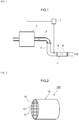
- FIG. 1 is a diagram that schematically illustrates an internal combustion engine 2 and the exhaust gas purification apparatus 1 disposed in the exhaust system of this internal combustion engine 2.
- a mixed gas containing oxygen and fuel gas is supplied to the internal combustion engine (engine) according to this embodiment.
- the internal combustion engine causes this fuel gas to undergo combustion and converts the combustion energy to mechanical energy.
- the combusted mixed gas is converted into an exhaust gas and is discharged into the exhaust system.
- the internal combustion engine 2 in the configuration shown in Fig. 1 is constructed of an automobile gasoline engine as its main unit.
- An exhaust manifold 3 is connected to an exhaust port (not shown) that connects the engine 2 to the exhaust system.
- the exhaust manifold 3 is connected to an exhaust pipe 4 through which the exhaust gas flows.
- the exhaust passage in this embodiment is formed by the exhaust manifold 3 and the exhaust pipe 4.
- the arrow in the figure shows the direction of exhaust gas through flow.
- the herein disclosed exhaust gas purification apparatus 1 is disposed in the exhaust system of the engine 2.
- This exhaust gas purification apparatus 1 is provided with a catalyst section 5, a filter section 6, and an ECU 7 and collects the particulate matter (PM) present in the exhaust gas while also purifying the harmful components (for example, carbon monoxide (CO), hydrocarbon (HC), and nitrogen oxides (NOx)) that are present in the discharged exhaust gas.
- the harmful components for example, carbon monoxide (CO), hydrocarbon (HC), and nitrogen oxides (NOx)
- the catalyst section 5 is constructed to be capable of purifying the three-way components (NOx, HC, CO) present in the exhaust gas and is disposed in the exhaust pipe 4 that communicates with the engine 2. As specifically shown in Fig. 1 , it is disposed on the downstream side of the exhaust pipe 4.
- the type of catalyst section 5 is not particularly limited.
- the catalyst section 5 may be, for example, a catalyst in which precious metal, e.g., platinum (Pt), palladium (Pd), rhodium (Rh), and so forth, is loaded.
- a downstream catalyst section may also be disposed in the exhaust pipe 4 on the downstream side of the filter section 6. The specific structure of this catalyst section 5 is not a characteristic feature of the present invention and a detailed description thereof is thus omitted here.
- the filter section 6 is disposed on the downstream side of the catalyst section 5.
- the filter section 6 is provided with a gasoline particulate filter (GPF) capable of collecting and removing the particulate matter (referred to hereafter simply as "PM") present in the exhaust gas.
- GPF gasoline particulate filter
- PM particulate matter
- Fig. 2 is a perspective diagram of a particulate filter 100.
- Fig. 3 is a schematic diagram provided by enlarging a portion of a cross section of the particulate filter 100 taken in the axial direction.
- the particulate filter 100 is provided with a substrate 10 having a wall-flow structure, a first catalyst region 20 (refer to Fig. 4 ), and a second catalyst region 30 (refer to Fig. 4 ).
- the substrate 10, the first catalyst region 20, and the second catalyst region 30 are successively described in the following.
- a substrate formed from a ceramic e.g., cordierite, silicon carbide (SiC), and so forth, or an alloy (e.g., stainless steel) can be advantageously used.
- a substrate having a cylindrical outer shape is one example.
- an elliptical cylindrical shape or a polygonal cylindrical shape may be used for the outer shape of the substrate as a whole.
- This substrate 10 has an entry-side cell 12 in which only the exhaust gas inflow-side end part is open, an exit-side cell 14 residing adjacent to an entry-side cell 12 and in which only the exhaust gas outflow-side end part is open, and a porous partition 16 that divides the entry-side cell 12 from the exit-side cell 14.
- an exit-side cell 14 resides adjacent to an entry-side cell 12 and is open only at the exhaust gas outflow-side end part.
- the exhaust gas outflow-side end part of the entry-side cell 12 is plugged by a sealed part 12a
- the exhaust gas inflow-side end part of the exit-side cell 14 is plugged by a sealed part 14a.
- a suitable shape and size may be established for the entry-side cell 12 and the exit-side cell 14 considering the components and flow rate of the exhaust gas that is supplied to the filter 100.
- the shape of the entry-side cell 12 and the exit-side cell 14 may be various geometric shapes, e.g., quadrilateral shapes such as square, parallelogram, rectangle, or trapezoid; a triangle; another polygon (for example, a hexagon or octagon); or a circle.
- a partition 16 is formed between an adjacent entry-side cell 12 and exit-side cell 14.
- the entry-side cell 12 and the exit-side cell 14 are divided from each other by this partition 16.
- the partition 16 has a porous structure through which the exhaust gas can pass.
- the pressure loss ends up increasing when the porosity of the partition 16 is too small, while the mechanical strength of the filter 100 assumes a declining trend when the porosity of the partition 16 is too large, and either is thus disadvantageous.
- the thickness of the partition 16 is not particularly limited, but is favorably from about 200 ⁇ m to 800 ⁇ m. When the thickness of the partition is in this range, a suppressing effect on pressure loss increases is obtained without impairing the PM collection efficiency.
- Fig. 4 is an enlarged schematic diagram provided by enlarging the IV region in Fig. 3 .
- the partition 16 has a small pore 18a that has a relatively small pore diameter and a large pore 18b that has a relatively large pore diameter.
- the partition 16 is constructed such that the front side of the partition 16 can communicate with the rear side through an independent large pore 18b (or a chain of many large pores 18b and/or small pores 18a).
- a complex tortuous path is formed in the partition 16 by small pores 18a that do not communicate across the partition 16 in the thickness direction.
- a first catalyst region 20 is formed in the interior of the small pore 18a.
- a second catalyst region 30 is formed in the interior of the large pore 18b.
- the first catalyst region 20 is formed at the wall surface of the small pores 18a.
- the exhaust gas tends to have a longer residence because a complex tortuous path (nontraversing detour path) is formed in the partition 16 by the small pores 18a. Due to this, the exhaust gas can be efficiently purified through the formation of the first catalyst region 20 in the small pore 18a.
- the pore diameter of the small pores 18a in which the first catalyst region 20 is formed should be smaller than the pore diameter of the large pores 18b in which the second catalyst region 30 is formed.
- the average pore diameter of the small pore 18a in which the first catalyst region 20 is formed, based on mercury intrusion is not more than approximately 10 ⁇ m (for example, at least 0.1 ⁇ m and not more than 10 ⁇ m) and is more preferably not more than 8 ⁇ m and particularly preferably not more than 5 ⁇ m.
- the harmful components purified by the first catalyst region 20 are not particularly limited, but can be exemplified by HC, CO, and NOx.
- the first catalyst region 20 is provided with a support (not shown) and with precious metal (not shown) loaded on this support.
- the first catalyst region 20 should contain any one species or two species of precious metal from platinum (Pt), palladium (Pd), and rhodium (Rh).
- the first catalyst region 20 contains Pt as the precious metal in this embodiment.
- the Pt content in the first catalyst region 20 per 1 L of substrate volume is preferably approximately 0.1 g to 2 g (preferably 0.5 g to 1 g).
- the first catalyst region 20 may contain a precious metal other than Rh, Pt, or Pd.
- ruthenium (Ru), iridium (Ir), osmium (Os) and so forth can be used as the precious metal other than Rh, Pt, or Pd.
- the first catalyst region 20 is formed by loading the Pt on the support.
- This support typically a particulate
- metal oxides such as alumina (Al 2 O 3 ), zirconia (ZrO 2 ), ceria (CeO 2 ), silica (SiO 2 ), magnesia (MgO), and titanium oxide (titania : TiO 2 ) and by their solid solutions (for example, ceria-zirconia (CeO 2 -ZrO 2 ) composite oxide).
- ceria-zirconia composite oxide is preferred. Two or more of the preceding may also be used in combination.
- rare-earth elements e.g., lanthanum (La), yttrium (Y), and so forth
- alkaline-earth elements e.g., calcium and so forth
- transition metal elements e.g., manganese, manganese, manganese, manganese, magnesium, manganese, calcium and so forth
- rare-earth elements such as lanthanum and yttrium are advantageously used as stabilizers because they can improve the specific surface area at high temperatures without poisoning the catalytic function.
- preparation can be carried out by impregnating the support with an aqueous solution containing a Pt salt (for example, the nitrate) or a Pt complex (for example, the dinitrodiamine complex), followed by drying and baking.
- a Pt salt for example, the nitrate
- a Pt complex for example, the dinitrodiamine complex
- a metal oxide not loaded with a precious metal can be added to the herein disclosed first catalyst region 20.
- Stabilized alumina is an example of this metal oxide.
- the herein disclosed first catalyst region 20 may contain an NOx absorber that has an NOx storage capacity.
- the NOx absorber should have an NOx storage capacity whereby it absorbs NOx in the exhaust gas under conditions in which the air-fuel ratio of the exhaust gas is in a lean condition of oxygen excess and it releases the absorbed NOx when the air-fuel ratio switches to the rich side.
- a basic material containing one or two or more metals capable of donating electrons to NOx is preferably used for this NOx absorber.
- the metal can be exemplified by alkali metals such as potassium (K), sodium (Na), and cesium (Cs); alkaline-earth metals such as barium (Ba) and calcium (Ca); rare earths such as the lanthanoids; and silver (Ag), copper (Cu), iron (Fe), iridium (Ir), and so forth.
- alkali metals such as potassium (K), sodium (Na), and cesium (Cs)
- alkaline-earth metals such as barium (Ba) and calcium (Ca)
- rare earths such as the lanthanoids
- silver (Ag), copper (Cu), iron (Fe), iridium (Ir), and so forth barium compounds (for example, barium sulfate) have a high NOx storage capacity and are thus advantageous as the NOx absorber used in the herein disclosed exhaust gas purification apparatus.
- the content of the NOx absorber is preferably a content that satisfies 10 mass% to 25 mass% and is particularly preferably a content that satisfies 12 mass% to 20 mass%.
- the NOx absorber is disposed within the partition 16 in a randomly dispersed state along the flow direction of the exhaust gas, and because of this the NOx in the exhaust gas passing through the interior of the partition 16 can be favorably absorbed and released. An even higher purification performance can be achieved as a consequence.
- the second catalyst region 30 is formed on the wall surface of the large pores 18b. Since the large pores 18b communicate across the partition 16 in the thickness direction, this sets up a tendency for the exhaust gas to smoothly pass through. As a consequence, through the formation of the second catalyst region 30 in the large pores 18b, the exhaust gas can be purified while pressure loss increases are restrained.
- the pore diameter of the large pores 18b in which the second catalyst region 30 is formed should be larger than the pore diameter of the small pores 18a in which the first catalyst region 20 is formed.
- the average pore diameter of the large pores 18b in which the second catalyst region 30 is formed, based on mercury intrusion, is, more than 10 ⁇ m and not more than 100 ⁇ m, more preferably is at least 15 ⁇ m, and particularly preferably is at least 20 ⁇ m.
- the exhaust gas can be purified by the second catalyst region 30 formed in the large pore 18b while restraining pressure loss increases.
- the harmful components to be purified by the second catalyst region 30 are not particularly limited, but can be exemplified by HC, CO, and NOx.
- the second catalyst region 30 is provided with a support (not shown) and with precious metal (not shown) loaded on this support.
- the second catalyst region 30 should contain any one or two species of precious metal selected from among Pt, Pd, and Rh, which, however, is not or are not the precious metal (Pt here) contained in the first catalyst region 20.
- the second catalyst region 30 contains Rh as the precious metal.
- the Rh content in the second catalyst region 30 per 1 L of substrate volume is preferably about 0.1 g to 0.5 g. When this Rh content is too low, the catalytic activity provided by the Rh is then inadequate; when, on the other hand, the Rh content is too large, Rh particle growth then easily occurs and at the same time this is also disadvantageous from a cost standpoint.
- the second catalyst region 30 may contain a precious metal other than Rh, Pt, or Pd.
- ruthenium (Ru), iridium (Ir), osmium (Os) and so forth can be used as the precious metal other than Rh, Pt, or Pd.
- the second catalyst region 30 is formed by loading the Rh on the support.
- This support typically a particulate
- metal oxides such as alumina (Al 2 O 3 ), zirconia (ZrO 2 ), ceria (CeO 2 ), silica (SiO 2 ), magnesia (MgO), and titanium oxide (titania : TiO 2 ) and by their solid solutions (for example, ceria-zirconia (CeO 2 -ZrO 2 ) composite oxide).
- alumina Al 2 O 3
- ZrO 2 zirconia
- CeO 2 ceria
- silica SiO 2
- MgO magnesia
- titanium oxide titanium oxide
- titanium oxide titanium oxide
- rare-earth elements e.g., lanthanum (La), yttrium (Y), and so forth
- alkaline-earth elements e.g., calcium and so forth
- transition metal elements e.
- preparation can be carried out by impregnating the support with an aqueous solution containing an Rh salt (for example, the nitrate) or an Rh complex (for example, the tetraammine complex), followed by drying and baking.
- an Rh salt for example, the nitrate
- an Rh complex for example, the tetraammine complex
- the herein disclosed second catalyst region 30 may contain an oxygen storage capacity (OSC) material that has an oxygen storage capacity.
- the OSC material should store the oxygen in the exhaust gas when the air-fuel ratio of the exhaust gas is lean (i.e., atmosphere on the oxygen excess side) and release the stored oxygen when the air-fuel ratio in the exhaust gas is rich (i.e., atmosphere on the fuel excess side).
- This OSC material can be exemplified by cerium oxide (ceria: CeO 2 ) and ceria-containing composite oxides (for example, ceria-zirconia composite oxide (CeO 2 -ZrO 2 composite oxide)).
- CeO 2 -ZrO 2 composite oxide has a high oxygen storage capacity and is thus advantageous as the OSC material for use in the herein disclosed exhaust gas purification apparatus.
- the content of this OSC material is preferably a content that satisfies 25 mass% to 50 mass% and is particularly preferably a content that satisfies 30 mass% to 40 mass%.
- the OSC material is disposed within the partition 16 in a randomly dispersed state along the flow direction of the exhaust gas, and because of this the oxygen in the exhaust gas passing through the interior of the partition 16 can be favorably absorbed and released. As a consequence, a more stable catalytic performance is obtained and the purification performance by the catalyst is further improved.
- the formation of the first catalyst region 20 and the second catalyst region 30 may be carried out based on different slurries for the first catalyst region 20 and the second catalyst region 30. For example, a first slurry for forming the first catalyst region 20 and a second slurry for forming the second catalyst region 30 may be prepared.
- the first slurry contains a suitable medium (for example, deionized water), an NOx absorber, stabilized alumina, and a powder provided by loading Pt on the aforementioned support.
- a suitable medium for example, deionized water
- the viscosity, solids concentration, particle diameter of the particles present in the first slurry typically a powder of the precious metal-loaded support), and so forth of the first slurry are adjusted as appropriate so as to facilitate flow into the small pore 18a of the partition 16.
- a binder is preferably incorporated in the first slurry in order to bring about a suitable adherence of the first slurry to the interior of the partition 16.
- the use of, for example, an alumina sol, silica sol, and so forth for the binder is preferred.
- the second slurry contains a suitable medium (for example, deionized water), an OSC material, and a powder provided by supporting Rh on the aforementioned support.
- a suitable medium for example, deionized water
- the viscosity, solids concentration, particle diameter of the particles present in the second slurry typically a powder of the precious metal-loaded support), and so forth of the second slurry are adjusted as appropriate so as to facilitate flow into the large pore 18b of the partition 16.
- a binder may be incorporated in the second slurry in order to bring about a suitable adherence of the second slurry to the interior of the partition 16.
- the use of, for example, an alumina sol, silica sol, and so forth for the binder is preferred.
- the interior of the partition 16 is first coated with the first slurry when the first catalyst region 20 and the second catalyst region 30 are to be formed.
- the partition 16 may be immersed for a prescribed period of time in the first slurry and may then be withdrawn. After the partition 16 has been withdrawn from the first slurry, the excess first slurry may be eliminated by blowing with compressed gas (or by suction).
- the first slurry readily flows under the effects of capillary phenomena into the small pore 18a having a relatively small pore diameter. Due to this, the first slurry preferentially flows into the small pore 18a of the partition 16 when the partition 16 is immersed in the first slurry.
- the interior of the partition 16 is then suction coated with the second slurry.
- the partition 16 may be immersed in the second slurry for a prescribed period of time followed by removal.
- the viscosity and solids concentration of the second slurry are adjusted as appropriate such that the second slurry easily flows into the large pore 18b of the partition 16.
- the small pore 18a is already coated with the first catalyst region 20.
- the second slurry preferentially flows into the large pore 18b of the partition 16.
- drying and baking may then be carried out.
- the second catalyst region 30 is thereby formed on the wall surface of the large pore 18b.
- a method can thus be provided for producing a particulate filter that has a substrate having a wall-flow structure and including an entry-side cell in which only an exhaust gas inflow-side end part is open, an exit-side cell residing adjacent to an entry-side cell and in which only an exhaust gas outflow-side end part is open, and a porous partition that divides the entry-side cell from the exit-side cell; a first catalyst region formed in small pores having relatively small pore diameters among internal pores in the partition; and a second catalyst region formed in large pores having relatively large pore diameters among the internal pores in the partition, wherein the first catalyst region contains a support and any one or two species of precious metal selected from Pt, Pd, and Rh loaded on the support, and the second catalyst region contains a support and any one or two species of precious metal selected from Pt, Pd, and Rh loaded on the support and other than at least the precious metal present in the first catalyst region.
- This production method comprises:
- the viscosity and solids concentration of the first slurry and the average particle diameter of the particles in the first slurry can be established as appropriate so as to enable the first slurry to flow into the small pores.
- the viscosity and solids concentration of the second slurry and the average particle diameter of the particles present in the second slurry can be established as appropriate so as to enable the second slurry to flow into the large pores.
- the first catalyst region formation step comprises immersing the partition in the first slurry (immersion step) and removing the partition from the first slurry and thereafter eliminating the excess first slurry by blowing with a compressed gas (slurry removal step).
- immersion step immersing the partition in the first slurry
- slurry removal step removing the partition from the first slurry and thereafter eliminating the excess first slurry by blowing with a compressed gas
- the conditions in the slurry removal step during blowing with compressed gas for example, the pressure of the gas and the impingement time
- the slurry removal step can then be carried out by blowing with the gas in accordance with the conditions thereby established.
- the particulate filter produced by this method can be advantageously used as the filter section in an exhaust gas purification apparatus.
- exhaust gas flows into this particulate filter 100 through the entry-side cell 12 in the substrate 10.
- the exhaust gas that has flowed in through the entry-side cell 12 passes through the porous partition 16 and thereby reaches the exit-side cell 14.
- the arrows in Fig. 3 show the route by which the exhaust gas that has flowed in through the entry-side cell 12 passes through the partition 16 and reaches the exit-side cell 14.
- the partition 16 has a porous structure, the particulate matter (PM) is collected at the surface of the partition 16 and within the pores in the interior of the partition 16 while the exhaust gas is passing through the partition 16.
- the harmful components in the exhaust gas are purified while the exhaust gas is passing through the interior of the partition 16.
- the exhaust gas that has passed through the partition 16 and has reached the exit-side cell 14 is discharged through the opening on the exhaust gas outflow side to the outside of the filter 100.
- the present construction can thus provide an exhaust gas purification apparatus 1 that has a markedly improved exhaust gas purification performance while supporting a reduction in pressure losses.
- test example is described in the following in relation to the present invention, but this should not be taken to mean that the present invention is limited to what is given in the following test example.
- Ceria-zirconia composite oxide was prepared as the support for the formation of the first catalyst region and was immersed in a solution of dinitrodiamine Pt as the precious metal catalyst solution; this was followed by evaporation to dryness to prepare a Pt/ceria-zirconia composite oxide support powder loaded with 1.91 mass% Pt. 62.2 mass parts of this Pt/ceria-zirconia composite oxide support powder, 36.61 mass parts of La-stabilized alumina, 18.32 mass parts of BaSO 4 , and 2.44 mass parts of an alumina binder were mixed with deionized water to prepare a first slurry.
- a wall flow-type cordierite substrate (103 mm diameter, 105 mm total length) was then immersed in this first slurry; the excess slurry was blown off by blowing with compressed gas; and drying and baking were carried out to then form a first catalyst region 20 in the interior of the partition 16.
- the mass of the first catalyst region per 1 L of substrate volume was 52.85 g and the mass of the Pt per 1 L of substrate volume was 0.5251 g.
- La-stabilized alumina was prepared as the support for formation of the second catalyst region and was immersed in an Rh nitrate solution as the precious metal catalyst solution; this was followed by evaporation to dryness to prepare an Rh/alumina support powder loaded with 0.8 mass% Rh. 36.9 mass parts of this Rh/alumina support powder, 36.61 mass parts of ceria-zirconia composite oxide, and 4.88 mass parts of an alumina binder were mixed with deionized water to prepare a second slurry. The aforementioned wall-flow substrate was then immersed in this second slurry; the excess slurry was blown off; and drying and baking were carried out to then form a second catalyst region 30 in the interior of the partition 16.
- the mass of the second catalyst region per 1 L of substrate volume was 34.65 g and the mass of the Rh per 1 L of substrate volume was 0.1313 g.
- a filter catalyst having the first catalyst region 20 and the second catalyst region 30 formed in the interior of the partition was thus produced proceeding as described above.
- FIG. 5 An SEM image of the cross section of the obtained filter catalyst is shown in Fig. 5 .
- the state of dispersion by the Pt was also observed by electron probe for microanalysis (EPMA).
- the results are shown in Fig. 6 .
- the state of dispersion by the Rh was also observed by EPMA.
- the results are shown in Fig. 7 .
- Figs. 5 and 6 by mapping the Pt using EPMA, it was confirmed that the Pt-containing first catalyst region 20 was formed mainly in the small pores 18a of the partition 16.
- FIGs. 5 and 7 by mapping the Rh using EPMA, it was confirmed that the Rh-containing second catalyst region 30 was formed mainly in the large pores 18b of the partition 16.
- a filter catalyst was prepared in which a mixed catalyst region of Pt and Rh was formed in the interior of the partition.
- 36.9 mass parts of the Rh/alumina support powder, 36.61 mass parts of ceria-zirconia composite oxide, 62.2 mass parts of the Pt/ceria-zirconia composite oxide support powder, 36.61 mass parts of alumina, and 18.32 mass parts of BaSO 4 were mixed with deionized water to prepare a slurry for the formation of a mixed catalyst region.
- a wall flow-type substrate was then immersed in this slurry; the excess slurry was blown off; and drying and baking were then carried out to form a mixed catalyst region in the interior of the partition.
- the Pt mass and Rh mass per 1 L of substrate volume were the same as in the example.
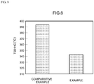
- Fig. 8 is a graph that shows the 50% purification temperature for the example and comparative example.
- the 50% purification temperature for HC exceeded 390°C with the filter catalyst according to the comparative example.
- the Pt was not separated from the Rh and it is hypothesized that sintering (alloying) between the Pt and Rh developed and that the catalytic performance declined due to this.
- the filter catalyst according to the example had a lower 50% purification temperature for HC and thus had a better catalytic activity. It is hypothesized that the catalytic performance was improved in the example as a result of an inhibition of sintering (alloying) between the Pt and Rh brought about by the separate loading of the Pt from the Rh in the small pores and large pores within the partition. It was thus confirmed based on this result that the catalytic performance could be improved by separately loading the Pt in the small pores and the Rh in the large pores within the partition.
- Pt is disposed in the small pore 18a and Rh is disposed in the large pore 18b, but there is no limitation to this.
- Pt may be disposed in the large pore 18b and Rh may be disposed in the small pore 18a. In this case, the effects indicated above can again be obtained because the Pt and Rh are supported separately within the partition.
- Pd may be present in the first catalyst region 20 in place of the Pt or together with the Pt.
- each member and position in the exhaust gas purification apparatus 1 may also be altered.
- a catalyst section is located upstream from the filter section in the example given in Fig. 1 , but the catalyst section may even be omitted.
- This exhaust gas purification apparatus 1 is particularly advantageous as an apparatus for purifying the harmful components in an exhaust gas having a relatively high exhaust temperature, for example, as in a gasoline engine.
- the exhaust gas purification apparatus 1 according to the present invention is not limited to the application of purifying the harmful components in the exhaust gases from gasoline engines and can be used in various applications for purifying the harmful components in the exhaust gases discharged from other types of engines (for example, diesel engines).
- the present invention can provide an exhaust gas purification apparatus that can provide an improved exhaust gas purification performance and that can do so while supporting a reduction in pressure losses.
Landscapes
- Chemical & Material Sciences (AREA)
- Engineering & Computer Science (AREA)
- Chemical Kinetics & Catalysis (AREA)
- Organic Chemistry (AREA)
- Materials Engineering (AREA)
- Combustion & Propulsion (AREA)
- Mechanical Engineering (AREA)
- General Engineering & Computer Science (AREA)
- Health & Medical Sciences (AREA)
- Oil, Petroleum & Natural Gas (AREA)
- Analytical Chemistry (AREA)
- General Chemical & Material Sciences (AREA)
- Environmental & Geological Engineering (AREA)
- Biomedical Technology (AREA)
- Toxicology (AREA)
- Emergency Medicine (AREA)
- Catalysts (AREA)
- Exhaust Gas After Treatment (AREA)
- Exhaust Gas Treatment By Means Of Catalyst (AREA)
- Nanotechnology (AREA)
- Processes For Solid Components From Exhaust (AREA)
Claims (5)
- Abgasreinigungsvorrichtung zur Anordnung in einem Abgaskanal eines Verbrennungsmotors und zum Reinigen eines aus dem Verbrennungsmotor ausgestoßenen Abgases, wobei die Abgasreinigungsvorrichtung umfasst:ein Substrat mit einer Wandströmungsstruktur und mit einer einlassseitigen Zelle, bei der nur ein einlassseitiger Endabschnitt des Abgases offen ist, einer auslassseitigen Zelle, die angrenzend an eine einlassseitige Zelle angeordnet ist, und bei der nur ein auslassseitiger Endabschnitt des Abgases offen ist, und einer porösen Trennwand, die die einlassseitige Zelle von der auslassseitigen Zelle trennt;einen ersten katalytischen Bereich, der in kleinen Poren mit relativ kleinen Porendurchmessern unter den inneren Poren der Trennwand gebildet ist; undeinen zweiten katalytischen Bereich, der in großen Poren mit relativ großen Porendurchmessern unter den inneren Poren der Trennwand gebildet ist, wobeider erste katalytische Bereich einen Träger und ein oder zwei Arten von Edelmetallen enthält, die ausgewählt sind aus Pt, Pd und Rh, die auf den Träger geladen sind, undder zweite katalytische Bereich einen Träger und eine oder zwei Arten von Edelmetall enthält, die ausgewählt sind aus Pt, Pd und Rh, die auf den Träger geladen sind, und sich von mindestens dem Edelmetall unterscheiden, das in dem ersten katalytischen Bereich vorhanden ist,wobei der durchschnittliche Porendurchmesser der kleinen Poren, in denen der erste katalytische Bereich gebildet ist, nicht mehr als 10 µm beträgt, undder durchschnittliche Porendurchmesser der großen Poren, in denen der zweite katalytische Bereich gebildet ist, größer als 10 µm und nicht größer als 100 µm ist,wobei der durchschnittliche Porendurchmesser durch Quecksilberintrusion gemessen wird.
- Abgasreinigungsvorrichtung nach Anspruch 1, wobei
der erste katalytische Bereich Pt als Edelmetall enthält, und
der zweite katalytische Bereich Rh als Edelmetall enthält. - Abgasreinigungsvorrichtung nach Anspruch 1 oder 2, wobei pro 1 L an Substratvolumen der Pt-Gehalt in dem ersten katalytischen Bereich 0,3 g bis 1 g beträgt, und
der Rh-Gehalt in dem zweiten katalytischen Bereich 0,1 g bis 0,5 g beträgt. - Abgasreinigungsvorrichtung nach Anspruch 2 oder 3, wobei der erste katalytische Bereich einen Stickoxid (NOx)-Absorber enthält, der eine NOx-Speicherkapazität aufweist.
- Abgasreinigungsvorrichtung nach einem der Ansprüche 2 bis 4, wobei der zweite katalytische Bereich ein Material mit Sauerstoffspeicherkapazität (OSC) enthält, das eine Sauerstoffspeicherkapazität aufweist.
Applications Claiming Priority (2)
| Application Number | Priority Date | Filing Date | Title |
|---|---|---|---|
| JP2014213110A JP6279448B2 (ja) | 2014-10-17 | 2014-10-17 | 排ガス浄化装置 |
| PCT/JP2015/078408 WO2016060029A1 (ja) | 2014-10-17 | 2015-10-06 | 排ガス浄化装置 |
Publications (3)
| Publication Number | Publication Date |
|---|---|
| EP3207977A1 EP3207977A1 (de) | 2017-08-23 |
| EP3207977A4 EP3207977A4 (de) | 2017-10-18 |
| EP3207977B1 true EP3207977B1 (de) | 2020-07-15 |
Family
ID=55746576
Family Applications (1)
| Application Number | Title | Priority Date | Filing Date |
|---|---|---|---|
| EP15850326.8A Active EP3207977B1 (de) | 2014-10-17 | 2015-10-06 | Abgasreinigungsvorrichtung |
Country Status (4)
| Country | Link |
|---|---|
| US (1) | US10201805B2 (de) |
| EP (1) | EP3207977B1 (de) |
| JP (1) | JP6279448B2 (de) |
| WO (1) | WO2016060029A1 (de) |
Families Citing this family (28)
| Publication number | Priority date | Publication date | Assignee | Title |
|---|---|---|---|---|
| CN108698028B (zh) * | 2016-03-01 | 2022-01-14 | 株式会社科特拉 | 排气净化催化剂 |
| CN110730858A (zh) * | 2017-04-04 | 2020-01-24 | 巴斯夫公司 | 集成排放控制系统 |
| EP3616791A4 (de) * | 2017-04-28 | 2021-01-06 | Umicore Shokubai Japan Co., Ltd. | Abgasreinigungskatalysator und abgasreinigungsverfahren damit |
| EP3501648B1 (de) | 2017-12-19 | 2023-10-04 | Umicore Ag & Co. Kg | Katalytisch aktives partikelfilter |
| DE202017007046U1 (de) | 2017-12-19 | 2019-04-29 | Umicore Ag & Co. Kg | Katalytisch aktives Partikelfilter |
| EP3505246B1 (de) | 2017-12-19 | 2019-10-23 | Umicore Ag & Co. Kg | Katalytisch aktives partikelfilter |
| EP3505245B1 (de) | 2017-12-19 | 2019-10-23 | Umicore Ag & Co. Kg | Katalytisch aktives partikelfilter |
| DE202017007047U1 (de) | 2017-12-19 | 2019-04-29 | Umicore Ag & Co. Kg | Katalytisch aktives Partikelfilter |
| US11161098B2 (en) * | 2018-05-18 | 2021-11-02 | Umicore Ag & Co. Kg | Three-way catalyst |
| EP3829763A1 (de) * | 2018-07-27 | 2021-06-09 | Johnson Matthey Public Limited Company | Verbesserte twc-katalysatoren mit hoher dotiermittelunterstützung |
| JP7065551B2 (ja) * | 2018-08-09 | 2022-05-12 | エヌ・イーケムキャット株式会社 | 触媒塗工ガソリンパティキュレートフィルター及びその製造方法 |
| EP3842142B1 (de) * | 2018-08-22 | 2024-11-06 | Mitsui Mining & Smelting Co., Ltd. | Abgasreinigungskatalysator |
| DE102019100107A1 (de) * | 2019-01-04 | 2020-07-09 | Umicore Ag & Co. Kg | Katalytisch aktives Filtersubstrat und Verfahren zur Herstellung sowie deren Verwendung |
| WO2020153309A1 (ja) * | 2019-01-22 | 2020-07-30 | 三井金属鉱業株式会社 | 排ガス浄化用触媒 |
| JP7195995B2 (ja) | 2019-03-27 | 2022-12-26 | 株式会社キャタラー | 排ガス浄化用触媒 |
| US12343713B2 (en) | 2019-03-29 | 2025-07-01 | Umicore Ag & Co. Kg | Catalytically active particulate filter |
| EP3737491B1 (de) | 2019-03-29 | 2022-05-11 | UMICORE AG & Co. KG | Katalytisch aktives partikelfilter |
| EP3946692A1 (de) | 2019-03-29 | 2022-02-09 | UMICORE AG & Co. KG | Katalytisch aktives partikelfilter |
| JP7120959B2 (ja) * | 2019-04-22 | 2022-08-17 | トヨタ自動車株式会社 | 構造体 |
| JP7211893B2 (ja) * | 2019-05-24 | 2023-01-24 | トヨタ自動車株式会社 | 排ガス浄化装置 |
| JP6815443B2 (ja) | 2019-06-26 | 2021-01-20 | 株式会社キャタラー | 排ガス浄化触媒装置 |
| EP3997315A4 (de) * | 2019-07-12 | 2023-07-19 | BASF Corporation | Katalysatorträger mit einer strahlenförmig abgegrenzten beschichtung |
| JP7027614B2 (ja) * | 2019-12-18 | 2022-03-01 | 三井金属鉱業株式会社 | 排ガス浄化用触媒 |
| JP7381372B2 (ja) | 2020-03-12 | 2023-11-15 | トヨタ自動車株式会社 | 排ガス浄化装置 |
| JP2021143664A (ja) * | 2020-03-13 | 2021-09-24 | トヨタ自動車株式会社 | 排ガス浄化装置 |
| EP4140567A3 (de) * | 2021-08-31 | 2023-03-29 | Johnson Matthey Public Limited Company | Mit übergangsmetall integriertes aluminiumoxid für verbesserte dreiwegkatalysatoren |
| JP2023135093A (ja) * | 2022-03-15 | 2023-09-28 | トヨタ自動車株式会社 | 排ガス浄化用触媒の製造方法 |
| DE102023132075A1 (de) * | 2023-11-17 | 2025-05-22 | Umicore Ag & Co. Kg | Katalytischer Partikelfilter |
Family Cites Families (11)
| Publication number | Priority date | Publication date | Assignee | Title |
|---|---|---|---|---|
| JP3736373B2 (ja) * | 2001-03-29 | 2006-01-18 | マツダ株式会社 | エンジンの排気浄化装置 |
| JP2007185571A (ja) * | 2006-01-11 | 2007-07-26 | Toyota Central Res & Dev Lab Inc | 排ガス浄化用触媒及びその製造方法 |
| WO2007094379A1 (ja) * | 2006-02-14 | 2007-08-23 | Ngk Insulators, Ltd. | ハニカム構造体及びハニカム触媒体 |
| DE102007046158B4 (de) * | 2007-09-27 | 2014-02-13 | Umicore Ag & Co. Kg | Verwendung eines katalytisch aktiven Partikelfilters zur Entfernung von Partikeln aus dem Abgas von mit überwiegend stöchiometrischem Luft/Kraftstoff-Gemisch betriebenen Verbrennungsmotoren |
| US8758695B2 (en) * | 2009-08-05 | 2014-06-24 | Basf Se | Treatment system for gasoline engine exhaust gas |
| CN103097021B (zh) * | 2010-06-10 | 2015-03-11 | 巴斯夫欧洲公司 | 具有降低的Rh载荷的NOx存储催化剂 |
| BR112014016404A8 (pt) * | 2012-01-23 | 2017-07-04 | N E Chemcat Corp | material de alumina, e, catalisador para purificação de gás de exaustão |
| EP2816205B1 (de) * | 2012-02-14 | 2021-08-18 | Toyota Jidosha Kabushiki Kaisha | Abgasreinigungsvorrichtung für einen verbrennungsmotor |
| JP2014094360A (ja) * | 2012-11-12 | 2014-05-22 | Cataler Corp | 排気ガス浄化用フィルター及び排気ガス浄化用フィルターの製造方法 |
| JP5619199B2 (ja) * | 2013-02-07 | 2014-11-05 | 株式会社キャタラー | スラリーの粘度調整方法およびスラリーの製造方法 |
| JP6263991B2 (ja) * | 2013-11-28 | 2018-01-24 | マツダ株式会社 | 触媒材の製造方法、並びにそれを用いた触媒付パティキュレートフィルタの製造方法及びガソリンエンジン用三元触媒の製造方法。 |
-
2014
- 2014-10-17 JP JP2014213110A patent/JP6279448B2/ja active Active
-
2015
- 2015-10-06 US US15/518,086 patent/US10201805B2/en active Active
- 2015-10-06 EP EP15850326.8A patent/EP3207977B1/de active Active
- 2015-10-06 WO PCT/JP2015/078408 patent/WO2016060029A1/ja not_active Ceased
Non-Patent Citations (1)
| Title |
|---|
| None * |
Also Published As
| Publication number | Publication date |
|---|---|
| JP6279448B2 (ja) | 2018-02-14 |
| WO2016060029A1 (ja) | 2016-04-21 |
| US20180001308A1 (en) | 2018-01-04 |
| EP3207977A1 (de) | 2017-08-23 |
| EP3207977A4 (de) | 2017-10-18 |
| US10201805B2 (en) | 2019-02-12 |
| JP2016077980A (ja) | 2016-05-16 |
Similar Documents
| Publication | Publication Date | Title |
|---|---|---|
| EP3207977B1 (de) | Abgasreinigungsvorrichtung | |
| EP3207978B1 (de) | Abgasreinigungsvorrichtung | |
| JP6346642B2 (ja) | 排ガス浄化用触媒 | |
| US10018095B2 (en) | Exhaust gas purification device | |
| CN107073463B (zh) | 废气净化用催化剂 | |
| US10159934B2 (en) | Exhaust gas purification catalyst | |
| JP6964580B2 (ja) | 排ガス浄化用触媒 | |
| CN107249737B (zh) | 排气净化用催化剂 | |
| JP4833605B2 (ja) | 排ガス浄化用触媒 | |
| JP2022514532A (ja) | 層状三元変換(twc)触媒およびその触媒を製造する方法 | |
| WO2016141142A1 (en) | LEAN NOx TRAP WITH ENHANCED HIGH AND LOW TEMPERATURE PERFORMANCE | |
| JP2019063700A (ja) | 排ガス浄化用触媒 | |
| EP4190446A1 (de) | Abgasreinigungskatalysator | |
| EP4393587A1 (de) | Abgasreinigungssystem für einen benzinmotor und abgasreinigungskatalysator | |
| WO2020255687A1 (ja) | パティキュレートフィルタ | |
| JP7130622B2 (ja) | 排ガス浄化用触媒 | |
| WO2020262623A1 (ja) | パティキュレートフィルタ | |
| JP7798799B2 (ja) | 微粒子フィルタ、内燃機関の排ガスから粒子状物質を除去する方法、及び微粒子フィルタの製造方法 | |
| JP6542690B2 (ja) | フィルタ触媒の製造方法 | |
| US11918986B2 (en) | Exhaust gas purification device | |
| CN111790270A (zh) | 过滤器催化剂、废气净化装置和过滤器催化剂的制造方法 | |
| JP7178432B2 (ja) | 排気浄化フィルタ | |
| JP2025101761A (ja) | パティキュレートフィルタおよび内部コート用スラリー |
Legal Events
| Date | Code | Title | Description |
|---|---|---|---|
| STAA | Information on the status of an ep patent application or granted ep patent |
Free format text: STATUS: THE INTERNATIONAL PUBLICATION HAS BEEN MADE |
|
| PUAI | Public reference made under article 153(3) epc to a published international application that has entered the european phase |
Free format text: ORIGINAL CODE: 0009012 |
|
| STAA | Information on the status of an ep patent application or granted ep patent |
Free format text: STATUS: REQUEST FOR EXAMINATION WAS MADE |
|
| 17P | Request for examination filed |
Effective date: 20170427 |
|
| AK | Designated contracting states |
Kind code of ref document: A1 Designated state(s): AL AT BE BG CH CY CZ DE DK EE ES FI FR GB GR HR HU IE IS IT LI LT LU LV MC MK MT NL NO PL PT RO RS SE SI SK SM TR |
|
| AX | Request for extension of the european patent |
Extension state: BA ME |
|
| A4 | Supplementary search report drawn up and despatched |
Effective date: 20170919 |
|
| RIC1 | Information provided on ipc code assigned before grant |
Ipc: F01N 3/023 20060101ALI20170913BHEP Ipc: B01J 23/63 20060101ALI20170913BHEP Ipc: F01N 3/035 20060101ALI20170913BHEP Ipc: F01N 3/10 20060101ALI20170913BHEP Ipc: F01N 3/022 20060101ALI20170913BHEP Ipc: F01N 3/02 20060101ALI20170913BHEP Ipc: B01J 35/04 20060101ALI20170913BHEP Ipc: F01N 3/28 20060101ALI20170913BHEP Ipc: B01D 53/94 20060101AFI20170913BHEP |
|
| DAV | Request for validation of the european patent (deleted) | ||
| DAX | Request for extension of the european patent (deleted) | ||
| GRAP | Despatch of communication of intention to grant a patent |
Free format text: ORIGINAL CODE: EPIDOSNIGR1 |
|
| STAA | Information on the status of an ep patent application or granted ep patent |
Free format text: STATUS: GRANT OF PATENT IS INTENDED |
|
| INTG | Intention to grant announced |
Effective date: 20200207 |
|
| GRAS | Grant fee paid |
Free format text: ORIGINAL CODE: EPIDOSNIGR3 |
|
| GRAA | (expected) grant |
Free format text: ORIGINAL CODE: 0009210 |
|
| STAA | Information on the status of an ep patent application or granted ep patent |
Free format text: STATUS: THE PATENT HAS BEEN GRANTED |
|
| AK | Designated contracting states |
Kind code of ref document: B1 Designated state(s): AL AT BE BG CH CY CZ DE DK EE ES FI FR GB GR HR HU IE IS IT LI LT LU LV MC MK MT NL NO PL PT RO RS SE SI SK SM TR |
|
| REG | Reference to a national code |
Ref country code: CH Ref legal event code: EP Ref country code: GB Ref legal event code: FG4D |
|
| REG | Reference to a national code |
Ref country code: IE Ref legal event code: FG4D |
|
| REG | Reference to a national code |
Ref country code: DE Ref legal event code: R096 Ref document number: 602015055939 Country of ref document: DE |
|
| REG | Reference to a national code |
Ref country code: AT Ref legal event code: REF Ref document number: 1290359 Country of ref document: AT Kind code of ref document: T Effective date: 20200815 |
|
| REG | Reference to a national code |
Ref country code: LT Ref legal event code: MG4D |
|
| REG | Reference to a national code |
Ref country code: AT Ref legal event code: MK05 Ref document number: 1290359 Country of ref document: AT Kind code of ref document: T Effective date: 20200715 |
|
| REG | Reference to a national code |
Ref country code: NL Ref legal event code: MP Effective date: 20200715 |
|
| PG25 | Lapsed in a contracting state [announced via postgrant information from national office to epo] |
Ref country code: SE Free format text: LAPSE BECAUSE OF FAILURE TO SUBMIT A TRANSLATION OF THE DESCRIPTION OR TO PAY THE FEE WITHIN THE PRESCRIBED TIME-LIMIT Effective date: 20200715 Ref country code: AT Free format text: LAPSE BECAUSE OF FAILURE TO SUBMIT A TRANSLATION OF THE DESCRIPTION OR TO PAY THE FEE WITHIN THE PRESCRIBED TIME-LIMIT Effective date: 20200715 Ref country code: NO Free format text: LAPSE BECAUSE OF FAILURE TO SUBMIT A TRANSLATION OF THE DESCRIPTION OR TO PAY THE FEE WITHIN THE PRESCRIBED TIME-LIMIT Effective date: 20201015 Ref country code: FI Free format text: LAPSE BECAUSE OF FAILURE TO SUBMIT A TRANSLATION OF THE DESCRIPTION OR TO PAY THE FEE WITHIN THE PRESCRIBED TIME-LIMIT Effective date: 20200715 Ref country code: GR Free format text: LAPSE BECAUSE OF FAILURE TO SUBMIT A TRANSLATION OF THE DESCRIPTION OR TO PAY THE FEE WITHIN THE PRESCRIBED TIME-LIMIT Effective date: 20201016 Ref country code: HR Free format text: LAPSE BECAUSE OF FAILURE TO SUBMIT A TRANSLATION OF THE DESCRIPTION OR TO PAY THE FEE WITHIN THE PRESCRIBED TIME-LIMIT Effective date: 20200715 Ref country code: BG Free format text: LAPSE BECAUSE OF FAILURE TO SUBMIT A TRANSLATION OF THE DESCRIPTION OR TO PAY THE FEE WITHIN THE PRESCRIBED TIME-LIMIT Effective date: 20201015 Ref country code: PT Free format text: LAPSE BECAUSE OF FAILURE TO SUBMIT A TRANSLATION OF THE DESCRIPTION OR TO PAY THE FEE WITHIN THE PRESCRIBED TIME-LIMIT Effective date: 20201116 Ref country code: ES Free format text: LAPSE BECAUSE OF FAILURE TO SUBMIT A TRANSLATION OF THE DESCRIPTION OR TO PAY THE FEE WITHIN THE PRESCRIBED TIME-LIMIT Effective date: 20200715 Ref country code: LT Free format text: LAPSE BECAUSE OF FAILURE TO SUBMIT A TRANSLATION OF THE DESCRIPTION OR TO PAY THE FEE WITHIN THE PRESCRIBED TIME-LIMIT Effective date: 20200715 |
|
| PG25 | Lapsed in a contracting state [announced via postgrant information from national office to epo] |
Ref country code: PL Free format text: LAPSE BECAUSE OF FAILURE TO SUBMIT A TRANSLATION OF THE DESCRIPTION OR TO PAY THE FEE WITHIN THE PRESCRIBED TIME-LIMIT Effective date: 20200715 Ref country code: RS Free format text: LAPSE BECAUSE OF FAILURE TO SUBMIT A TRANSLATION OF THE DESCRIPTION OR TO PAY THE FEE WITHIN THE PRESCRIBED TIME-LIMIT Effective date: 20200715 Ref country code: LV Free format text: LAPSE BECAUSE OF FAILURE TO SUBMIT A TRANSLATION OF THE DESCRIPTION OR TO PAY THE FEE WITHIN THE PRESCRIBED TIME-LIMIT Effective date: 20200715 Ref country code: IS Free format text: LAPSE BECAUSE OF FAILURE TO SUBMIT A TRANSLATION OF THE DESCRIPTION OR TO PAY THE FEE WITHIN THE PRESCRIBED TIME-LIMIT Effective date: 20201115 |
|
| PG25 | Lapsed in a contracting state [announced via postgrant information from national office to epo] |
Ref country code: NL Free format text: LAPSE BECAUSE OF FAILURE TO SUBMIT A TRANSLATION OF THE DESCRIPTION OR TO PAY THE FEE WITHIN THE PRESCRIBED TIME-LIMIT Effective date: 20200715 |
|
| REG | Reference to a national code |
Ref country code: DE Ref legal event code: R097 Ref document number: 602015055939 Country of ref document: DE |
|
| PG25 | Lapsed in a contracting state [announced via postgrant information from national office to epo] |
Ref country code: EE Free format text: LAPSE BECAUSE OF FAILURE TO SUBMIT A TRANSLATION OF THE DESCRIPTION OR TO PAY THE FEE WITHIN THE PRESCRIBED TIME-LIMIT Effective date: 20200715 Ref country code: RO Free format text: LAPSE BECAUSE OF FAILURE TO SUBMIT A TRANSLATION OF THE DESCRIPTION OR TO PAY THE FEE WITHIN THE PRESCRIBED TIME-LIMIT Effective date: 20200715 Ref country code: SM Free format text: LAPSE BECAUSE OF FAILURE TO SUBMIT A TRANSLATION OF THE DESCRIPTION OR TO PAY THE FEE WITHIN THE PRESCRIBED TIME-LIMIT Effective date: 20200715 Ref country code: IT Free format text: LAPSE BECAUSE OF FAILURE TO SUBMIT A TRANSLATION OF THE DESCRIPTION OR TO PAY THE FEE WITHIN THE PRESCRIBED TIME-LIMIT Effective date: 20200715 Ref country code: DK Free format text: LAPSE BECAUSE OF FAILURE TO SUBMIT A TRANSLATION OF THE DESCRIPTION OR TO PAY THE FEE WITHIN THE PRESCRIBED TIME-LIMIT Effective date: 20200715 Ref country code: CZ Free format text: LAPSE BECAUSE OF FAILURE TO SUBMIT A TRANSLATION OF THE DESCRIPTION OR TO PAY THE FEE WITHIN THE PRESCRIBED TIME-LIMIT Effective date: 20200715 |
|
| PLBE | No opposition filed within time limit |
Free format text: ORIGINAL CODE: 0009261 |
|
| STAA | Information on the status of an ep patent application or granted ep patent |
Free format text: STATUS: NO OPPOSITION FILED WITHIN TIME LIMIT |
|
| PG25 | Lapsed in a contracting state [announced via postgrant information from national office to epo] |
Ref country code: AL Free format text: LAPSE BECAUSE OF FAILURE TO SUBMIT A TRANSLATION OF THE DESCRIPTION OR TO PAY THE FEE WITHIN THE PRESCRIBED TIME-LIMIT Effective date: 20200715 |
|
| REG | Reference to a national code |
Ref country code: CH Ref legal event code: PL |
|
| 26N | No opposition filed |
Effective date: 20210416 |
|
| PG25 | Lapsed in a contracting state [announced via postgrant information from national office to epo] |
Ref country code: LU Free format text: LAPSE BECAUSE OF NON-PAYMENT OF DUE FEES Effective date: 20201006 Ref country code: SK Free format text: LAPSE BECAUSE OF FAILURE TO SUBMIT A TRANSLATION OF THE DESCRIPTION OR TO PAY THE FEE WITHIN THE PRESCRIBED TIME-LIMIT Effective date: 20200715 Ref country code: MC Free format text: LAPSE BECAUSE OF FAILURE TO SUBMIT A TRANSLATION OF THE DESCRIPTION OR TO PAY THE FEE WITHIN THE PRESCRIBED TIME-LIMIT Effective date: 20200715 |
|
| REG | Reference to a national code |
Ref country code: BE Ref legal event code: MM Effective date: 20201031 |
|
| PG25 | Lapsed in a contracting state [announced via postgrant information from national office to epo] |
Ref country code: LI Free format text: LAPSE BECAUSE OF NON-PAYMENT OF DUE FEES Effective date: 20201031 Ref country code: SI Free format text: LAPSE BECAUSE OF FAILURE TO SUBMIT A TRANSLATION OF THE DESCRIPTION OR TO PAY THE FEE WITHIN THE PRESCRIBED TIME-LIMIT Effective date: 20200715 Ref country code: BE Free format text: LAPSE BECAUSE OF NON-PAYMENT OF DUE FEES Effective date: 20201031 Ref country code: CH Free format text: LAPSE BECAUSE OF NON-PAYMENT OF DUE FEES Effective date: 20201031 |
|
| PG25 | Lapsed in a contracting state [announced via postgrant information from national office to epo] |
Ref country code: IE Free format text: LAPSE BECAUSE OF NON-PAYMENT OF DUE FEES Effective date: 20201006 |
|
| PG25 | Lapsed in a contracting state [announced via postgrant information from national office to epo] |
Ref country code: TR Free format text: LAPSE BECAUSE OF FAILURE TO SUBMIT A TRANSLATION OF THE DESCRIPTION OR TO PAY THE FEE WITHIN THE PRESCRIBED TIME-LIMIT Effective date: 20200715 Ref country code: MT Free format text: LAPSE BECAUSE OF FAILURE TO SUBMIT A TRANSLATION OF THE DESCRIPTION OR TO PAY THE FEE WITHIN THE PRESCRIBED TIME-LIMIT Effective date: 20200715 Ref country code: CY Free format text: LAPSE BECAUSE OF FAILURE TO SUBMIT A TRANSLATION OF THE DESCRIPTION OR TO PAY THE FEE WITHIN THE PRESCRIBED TIME-LIMIT Effective date: 20200715 |
|
| PG25 | Lapsed in a contracting state [announced via postgrant information from national office to epo] |
Ref country code: MK Free format text: LAPSE BECAUSE OF FAILURE TO SUBMIT A TRANSLATION OF THE DESCRIPTION OR TO PAY THE FEE WITHIN THE PRESCRIBED TIME-LIMIT Effective date: 20200715 |
|
| PGFP | Annual fee paid to national office [announced via postgrant information from national office to epo] |
Ref country code: DE Payment date: 20251020 Year of fee payment: 11 |
|
| PGFP | Annual fee paid to national office [announced via postgrant information from national office to epo] |
Ref country code: GB Payment date: 20251024 Year of fee payment: 11 |
|
| PGFP | Annual fee paid to national office [announced via postgrant information from national office to epo] |
Ref country code: FR Payment date: 20251029 Year of fee payment: 11 |