EP3203166B1 - Klimaanlage und verfahren zur steuerung davon - Google Patents
Klimaanlage und verfahren zur steuerung davon Download PDFInfo
- Publication number
- EP3203166B1 EP3203166B1 EP16199986.7A EP16199986A EP3203166B1 EP 3203166 B1 EP3203166 B1 EP 3203166B1 EP 16199986 A EP16199986 A EP 16199986A EP 3203166 B1 EP3203166 B1 EP 3203166B1
- Authority
- EP
- European Patent Office
- Prior art keywords
- load
- compressor
- operating frequency
- increase rate
- determined
- Prior art date
- Legal status (The legal status is an assumption and is not a legal conclusion. Google has not performed a legal analysis and makes no representation as to the accuracy of the status listed.)
- Active
Links
- 238000000034 method Methods 0.000 title claims description 26
- 238000001816 cooling Methods 0.000 claims description 29
- 239000003507 refrigerant Substances 0.000 claims description 27
- 238000005057 refrigeration Methods 0.000 claims description 24
- 238000012423 maintenance Methods 0.000 claims description 8
- 230000003213 activating effect Effects 0.000 claims description 2
- 230000004913 activation Effects 0.000 claims 1
- 230000007423 decrease Effects 0.000 description 24
- 238000010438 heat treatment Methods 0.000 description 23
- 239000007788 liquid Substances 0.000 description 15
- 230000003247 decreasing effect Effects 0.000 description 5
- 238000010586 diagram Methods 0.000 description 4
- 238000001704 evaporation Methods 0.000 description 4
- 238000009413 insulation Methods 0.000 description 4
- 238000001514 detection method Methods 0.000 description 3
- 238000004378 air conditioning Methods 0.000 description 2
- 238000013507 mapping Methods 0.000 description 2
- 238000007664 blowing Methods 0.000 description 1
- 238000005516 engineering process Methods 0.000 description 1
- 230000008020 evaporation Effects 0.000 description 1
- 230000006870 function Effects 0.000 description 1
Images



Classifications
-
- F—MECHANICAL ENGINEERING; LIGHTING; HEATING; WEAPONS; BLASTING
- F24—HEATING; RANGES; VENTILATING
- F24F—AIR-CONDITIONING; AIR-HUMIDIFICATION; VENTILATION; USE OF AIR CURRENTS FOR SCREENING
- F24F2110/00—Control inputs relating to air properties
- F24F2110/10—Temperature
-
- F—MECHANICAL ENGINEERING; LIGHTING; HEATING; WEAPONS; BLASTING
- F25—REFRIGERATION OR COOLING; COMBINED HEATING AND REFRIGERATION SYSTEMS; HEAT PUMP SYSTEMS; MANUFACTURE OR STORAGE OF ICE; LIQUEFACTION SOLIDIFICATION OF GASES
- F25B—REFRIGERATION MACHINES, PLANTS OR SYSTEMS; COMBINED HEATING AND REFRIGERATION SYSTEMS; HEAT PUMP SYSTEMS
- F25B49/00—Arrangement or mounting of control or safety devices
- F25B49/02—Arrangement or mounting of control or safety devices for compression type machines, plants or systems
-
- F—MECHANICAL ENGINEERING; LIGHTING; HEATING; WEAPONS; BLASTING
- F25—REFRIGERATION OR COOLING; COMBINED HEATING AND REFRIGERATION SYSTEMS; HEAT PUMP SYSTEMS; MANUFACTURE OR STORAGE OF ICE; LIQUEFACTION SOLIDIFICATION OF GASES
- F25B—REFRIGERATION MACHINES, PLANTS OR SYSTEMS; COMBINED HEATING AND REFRIGERATION SYSTEMS; HEAT PUMP SYSTEMS
- F25B49/00—Arrangement or mounting of control or safety devices
- F25B49/02—Arrangement or mounting of control or safety devices for compression type machines, plants or systems
- F25B49/025—Motor control arrangements
-
- F—MECHANICAL ENGINEERING; LIGHTING; HEATING; WEAPONS; BLASTING
- F24—HEATING; RANGES; VENTILATING
- F24F—AIR-CONDITIONING; AIR-HUMIDIFICATION; VENTILATION; USE OF AIR CURRENTS FOR SCREENING
- F24F1/00—Room units for air-conditioning, e.g. separate or self-contained units or units receiving primary air from a central station
- F24F1/0003—Room units for air-conditioning, e.g. separate or self-contained units or units receiving primary air from a central station characterised by a split arrangement, wherein parts of the air-conditioning system, e.g. evaporator and condenser, are in separately located units
-
- F—MECHANICAL ENGINEERING; LIGHTING; HEATING; WEAPONS; BLASTING
- F24—HEATING; RANGES; VENTILATING
- F24F—AIR-CONDITIONING; AIR-HUMIDIFICATION; VENTILATION; USE OF AIR CURRENTS FOR SCREENING
- F24F11/00—Control or safety arrangements
- F24F11/30—Control or safety arrangements for purposes related to the operation of the system, e.g. for safety or monitoring
-
- F—MECHANICAL ENGINEERING; LIGHTING; HEATING; WEAPONS; BLASTING
- F24—HEATING; RANGES; VENTILATING
- F24F—AIR-CONDITIONING; AIR-HUMIDIFICATION; VENTILATION; USE OF AIR CURRENTS FOR SCREENING
- F24F11/00—Control or safety arrangements
- F24F11/62—Control or safety arrangements characterised by the type of control or by internal processing, e.g. using fuzzy logic, adaptive control or estimation of values
-
- F—MECHANICAL ENGINEERING; LIGHTING; HEATING; WEAPONS; BLASTING
- F24—HEATING; RANGES; VENTILATING
- F24F—AIR-CONDITIONING; AIR-HUMIDIFICATION; VENTILATION; USE OF AIR CURRENTS FOR SCREENING
- F24F2110/00—Control inputs relating to air properties
-
- F—MECHANICAL ENGINEERING; LIGHTING; HEATING; WEAPONS; BLASTING
- F24—HEATING; RANGES; VENTILATING
- F24F—AIR-CONDITIONING; AIR-HUMIDIFICATION; VENTILATION; USE OF AIR CURRENTS FOR SCREENING
- F24F5/00—Air-conditioning systems or apparatus not covered by F24F1/00 or F24F3/00, e.g. using solar heat or combined with household units such as an oven or water heater
- F24F5/0007—Air-conditioning systems or apparatus not covered by F24F1/00 or F24F3/00, e.g. using solar heat or combined with household units such as an oven or water heater cooling apparatus specially adapted for use in air-conditioning
- F24F5/001—Compression cycle type
-
- F—MECHANICAL ENGINEERING; LIGHTING; HEATING; WEAPONS; BLASTING
- F25—REFRIGERATION OR COOLING; COMBINED HEATING AND REFRIGERATION SYSTEMS; HEAT PUMP SYSTEMS; MANUFACTURE OR STORAGE OF ICE; LIQUEFACTION SOLIDIFICATION OF GASES
- F25B—REFRIGERATION MACHINES, PLANTS OR SYSTEMS; COMBINED HEATING AND REFRIGERATION SYSTEMS; HEAT PUMP SYSTEMS
- F25B13/00—Compression machines, plants or systems, with reversible cycle
-
- F—MECHANICAL ENGINEERING; LIGHTING; HEATING; WEAPONS; BLASTING
- F25—REFRIGERATION OR COOLING; COMBINED HEATING AND REFRIGERATION SYSTEMS; HEAT PUMP SYSTEMS; MANUFACTURE OR STORAGE OF ICE; LIQUEFACTION SOLIDIFICATION OF GASES
- F25B—REFRIGERATION MACHINES, PLANTS OR SYSTEMS; COMBINED HEATING AND REFRIGERATION SYSTEMS; HEAT PUMP SYSTEMS
- F25B49/00—Arrangement or mounting of control or safety devices
- F25B49/02—Arrangement or mounting of control or safety devices for compression type machines, plants or systems
- F25B49/022—Compressor control arrangements
-
- F—MECHANICAL ENGINEERING; LIGHTING; HEATING; WEAPONS; BLASTING
- F24—HEATING; RANGES; VENTILATING
- F24F—AIR-CONDITIONING; AIR-HUMIDIFICATION; VENTILATION; USE OF AIR CURRENTS FOR SCREENING
- F24F11/00—Control or safety arrangements
- F24F11/62—Control or safety arrangements characterised by the type of control or by internal processing, e.g. using fuzzy logic, adaptive control or estimation of values
- F24F11/63—Electronic processing
- F24F11/64—Electronic processing using pre-stored data
-
- F—MECHANICAL ENGINEERING; LIGHTING; HEATING; WEAPONS; BLASTING
- F24—HEATING; RANGES; VENTILATING
- F24F—AIR-CONDITIONING; AIR-HUMIDIFICATION; VENTILATION; USE OF AIR CURRENTS FOR SCREENING
- F24F2140/00—Control inputs relating to system states
- F24F2140/10—Pressure
- F24F2140/12—Heat-exchange fluid pressure
-
- F—MECHANICAL ENGINEERING; LIGHTING; HEATING; WEAPONS; BLASTING
- F24—HEATING; RANGES; VENTILATING
- F24F—AIR-CONDITIONING; AIR-HUMIDIFICATION; VENTILATION; USE OF AIR CURRENTS FOR SCREENING
- F24F2140/00—Control inputs relating to system states
- F24F2140/50—Load
-
- F—MECHANICAL ENGINEERING; LIGHTING; HEATING; WEAPONS; BLASTING
- F25—REFRIGERATION OR COOLING; COMBINED HEATING AND REFRIGERATION SYSTEMS; HEAT PUMP SYSTEMS; MANUFACTURE OR STORAGE OF ICE; LIQUEFACTION SOLIDIFICATION OF GASES
- F25B—REFRIGERATION MACHINES, PLANTS OR SYSTEMS; COMBINED HEATING AND REFRIGERATION SYSTEMS; HEAT PUMP SYSTEMS
- F25B2313/00—Compression machines, plants or systems with reversible cycle not otherwise provided for
- F25B2313/029—Control issues
- F25B2313/0294—Control issues related to the outdoor fan, e.g. controlling speed
-
- F—MECHANICAL ENGINEERING; LIGHTING; HEATING; WEAPONS; BLASTING
- F25—REFRIGERATION OR COOLING; COMBINED HEATING AND REFRIGERATION SYSTEMS; HEAT PUMP SYSTEMS; MANUFACTURE OR STORAGE OF ICE; LIQUEFACTION SOLIDIFICATION OF GASES
- F25B—REFRIGERATION MACHINES, PLANTS OR SYSTEMS; COMBINED HEATING AND REFRIGERATION SYSTEMS; HEAT PUMP SYSTEMS
- F25B2313/00—Compression machines, plants or systems with reversible cycle not otherwise provided for
- F25B2313/031—Sensor arrangements
- F25B2313/0314—Temperature sensors near the indoor heat exchanger
-
- F—MECHANICAL ENGINEERING; LIGHTING; HEATING; WEAPONS; BLASTING
- F25—REFRIGERATION OR COOLING; COMBINED HEATING AND REFRIGERATION SYSTEMS; HEAT PUMP SYSTEMS; MANUFACTURE OR STORAGE OF ICE; LIQUEFACTION SOLIDIFICATION OF GASES
- F25B—REFRIGERATION MACHINES, PLANTS OR SYSTEMS; COMBINED HEATING AND REFRIGERATION SYSTEMS; HEAT PUMP SYSTEMS
- F25B2500/00—Problems to be solved
- F25B2500/19—Calculation of parameters
-
- F—MECHANICAL ENGINEERING; LIGHTING; HEATING; WEAPONS; BLASTING
- F25—REFRIGERATION OR COOLING; COMBINED HEATING AND REFRIGERATION SYSTEMS; HEAT PUMP SYSTEMS; MANUFACTURE OR STORAGE OF ICE; LIQUEFACTION SOLIDIFICATION OF GASES
- F25B—REFRIGERATION MACHINES, PLANTS OR SYSTEMS; COMBINED HEATING AND REFRIGERATION SYSTEMS; HEAT PUMP SYSTEMS
- F25B2500/00—Problems to be solved
- F25B2500/26—Problems to be solved characterised by the startup of the refrigeration cycle
-
- F—MECHANICAL ENGINEERING; LIGHTING; HEATING; WEAPONS; BLASTING
- F25—REFRIGERATION OR COOLING; COMBINED HEATING AND REFRIGERATION SYSTEMS; HEAT PUMP SYSTEMS; MANUFACTURE OR STORAGE OF ICE; LIQUEFACTION SOLIDIFICATION OF GASES
- F25B—REFRIGERATION MACHINES, PLANTS OR SYSTEMS; COMBINED HEATING AND REFRIGERATION SYSTEMS; HEAT PUMP SYSTEMS
- F25B2600/00—Control issues
- F25B2600/02—Compressor control
- F25B2600/021—Inverters therefor
-
- F—MECHANICAL ENGINEERING; LIGHTING; HEATING; WEAPONS; BLASTING
- F25—REFRIGERATION OR COOLING; COMBINED HEATING AND REFRIGERATION SYSTEMS; HEAT PUMP SYSTEMS; MANUFACTURE OR STORAGE OF ICE; LIQUEFACTION SOLIDIFICATION OF GASES
- F25B—REFRIGERATION MACHINES, PLANTS OR SYSTEMS; COMBINED HEATING AND REFRIGERATION SYSTEMS; HEAT PUMP SYSTEMS
- F25B2600/00—Control issues
- F25B2600/02—Compressor control
- F25B2600/025—Compressor control by controlling speed
- F25B2600/0253—Compressor control by controlling speed with variable speed
-
- F—MECHANICAL ENGINEERING; LIGHTING; HEATING; WEAPONS; BLASTING
- F25—REFRIGERATION OR COOLING; COMBINED HEATING AND REFRIGERATION SYSTEMS; HEAT PUMP SYSTEMS; MANUFACTURE OR STORAGE OF ICE; LIQUEFACTION SOLIDIFICATION OF GASES
- F25B—REFRIGERATION MACHINES, PLANTS OR SYSTEMS; COMBINED HEATING AND REFRIGERATION SYSTEMS; HEAT PUMP SYSTEMS
- F25B2600/00—Control issues
- F25B2600/25—Control of valves
- F25B2600/2513—Expansion valves
-
- F—MECHANICAL ENGINEERING; LIGHTING; HEATING; WEAPONS; BLASTING
- F25—REFRIGERATION OR COOLING; COMBINED HEATING AND REFRIGERATION SYSTEMS; HEAT PUMP SYSTEMS; MANUFACTURE OR STORAGE OF ICE; LIQUEFACTION SOLIDIFICATION OF GASES
- F25B—REFRIGERATION MACHINES, PLANTS OR SYSTEMS; COMBINED HEATING AND REFRIGERATION SYSTEMS; HEAT PUMP SYSTEMS
- F25B2700/00—Sensing or detecting of parameters; Sensors therefor
- F25B2700/04—Refrigerant level
-
- F—MECHANICAL ENGINEERING; LIGHTING; HEATING; WEAPONS; BLASTING
- F25—REFRIGERATION OR COOLING; COMBINED HEATING AND REFRIGERATION SYSTEMS; HEAT PUMP SYSTEMS; MANUFACTURE OR STORAGE OF ICE; LIQUEFACTION SOLIDIFICATION OF GASES
- F25B—REFRIGERATION MACHINES, PLANTS OR SYSTEMS; COMBINED HEATING AND REFRIGERATION SYSTEMS; HEAT PUMP SYSTEMS
- F25B2700/00—Sensing or detecting of parameters; Sensors therefor
- F25B2700/15—Power, e.g. by voltage or current
- F25B2700/151—Power, e.g. by voltage or current of the compressor motor
-
- F—MECHANICAL ENGINEERING; LIGHTING; HEATING; WEAPONS; BLASTING
- F25—REFRIGERATION OR COOLING; COMBINED HEATING AND REFRIGERATION SYSTEMS; HEAT PUMP SYSTEMS; MANUFACTURE OR STORAGE OF ICE; LIQUEFACTION SOLIDIFICATION OF GASES
- F25B—REFRIGERATION MACHINES, PLANTS OR SYSTEMS; COMBINED HEATING AND REFRIGERATION SYSTEMS; HEAT PUMP SYSTEMS
- F25B2700/00—Sensing or detecting of parameters; Sensors therefor
- F25B2700/17—Speeds
- F25B2700/171—Speeds of the compressor
-
- F—MECHANICAL ENGINEERING; LIGHTING; HEATING; WEAPONS; BLASTING
- F25—REFRIGERATION OR COOLING; COMBINED HEATING AND REFRIGERATION SYSTEMS; HEAT PUMP SYSTEMS; MANUFACTURE OR STORAGE OF ICE; LIQUEFACTION SOLIDIFICATION OF GASES
- F25B—REFRIGERATION MACHINES, PLANTS OR SYSTEMS; COMBINED HEATING AND REFRIGERATION SYSTEMS; HEAT PUMP SYSTEMS
- F25B2700/00—Sensing or detecting of parameters; Sensors therefor
- F25B2700/19—Pressures
- F25B2700/193—Pressures of the compressor
-
- F—MECHANICAL ENGINEERING; LIGHTING; HEATING; WEAPONS; BLASTING
- F25—REFRIGERATION OR COOLING; COMBINED HEATING AND REFRIGERATION SYSTEMS; HEAT PUMP SYSTEMS; MANUFACTURE OR STORAGE OF ICE; LIQUEFACTION SOLIDIFICATION OF GASES
- F25B—REFRIGERATION MACHINES, PLANTS OR SYSTEMS; COMBINED HEATING AND REFRIGERATION SYSTEMS; HEAT PUMP SYSTEMS
- F25B2700/00—Sensing or detecting of parameters; Sensors therefor
- F25B2700/19—Pressures
- F25B2700/193—Pressures of the compressor
- F25B2700/1931—Discharge pressures
-
- F—MECHANICAL ENGINEERING; LIGHTING; HEATING; WEAPONS; BLASTING
- F25—REFRIGERATION OR COOLING; COMBINED HEATING AND REFRIGERATION SYSTEMS; HEAT PUMP SYSTEMS; MANUFACTURE OR STORAGE OF ICE; LIQUEFACTION SOLIDIFICATION OF GASES
- F25B—REFRIGERATION MACHINES, PLANTS OR SYSTEMS; COMBINED HEATING AND REFRIGERATION SYSTEMS; HEAT PUMP SYSTEMS
- F25B2700/00—Sensing or detecting of parameters; Sensors therefor
- F25B2700/19—Pressures
- F25B2700/193—Pressures of the compressor
- F25B2700/1933—Suction pressures
-
- F—MECHANICAL ENGINEERING; LIGHTING; HEATING; WEAPONS; BLASTING
- F25—REFRIGERATION OR COOLING; COMBINED HEATING AND REFRIGERATION SYSTEMS; HEAT PUMP SYSTEMS; MANUFACTURE OR STORAGE OF ICE; LIQUEFACTION SOLIDIFICATION OF GASES
- F25B—REFRIGERATION MACHINES, PLANTS OR SYSTEMS; COMBINED HEATING AND REFRIGERATION SYSTEMS; HEAT PUMP SYSTEMS
- F25B2700/00—Sensing or detecting of parameters; Sensors therefor
- F25B2700/19—Pressures
- F25B2700/195—Pressures of the condenser
-
- F—MECHANICAL ENGINEERING; LIGHTING; HEATING; WEAPONS; BLASTING
- F25—REFRIGERATION OR COOLING; COMBINED HEATING AND REFRIGERATION SYSTEMS; HEAT PUMP SYSTEMS; MANUFACTURE OR STORAGE OF ICE; LIQUEFACTION SOLIDIFICATION OF GASES
- F25B—REFRIGERATION MACHINES, PLANTS OR SYSTEMS; COMBINED HEATING AND REFRIGERATION SYSTEMS; HEAT PUMP SYSTEMS
- F25B2700/00—Sensing or detecting of parameters; Sensors therefor
- F25B2700/19—Pressures
- F25B2700/197—Pressures of the evaporator
-
- F—MECHANICAL ENGINEERING; LIGHTING; HEATING; WEAPONS; BLASTING
- F25—REFRIGERATION OR COOLING; COMBINED HEATING AND REFRIGERATION SYSTEMS; HEAT PUMP SYSTEMS; MANUFACTURE OR STORAGE OF ICE; LIQUEFACTION SOLIDIFICATION OF GASES
- F25B—REFRIGERATION MACHINES, PLANTS OR SYSTEMS; COMBINED HEATING AND REFRIGERATION SYSTEMS; HEAT PUMP SYSTEMS
- F25B2700/00—Sensing or detecting of parameters; Sensors therefor
- F25B2700/21—Temperatures
- F25B2700/2104—Temperatures of an indoor room or compartment
-
- F—MECHANICAL ENGINEERING; LIGHTING; HEATING; WEAPONS; BLASTING
- F25—REFRIGERATION OR COOLING; COMBINED HEATING AND REFRIGERATION SYSTEMS; HEAT PUMP SYSTEMS; MANUFACTURE OR STORAGE OF ICE; LIQUEFACTION SOLIDIFICATION OF GASES
- F25B—REFRIGERATION MACHINES, PLANTS OR SYSTEMS; COMBINED HEATING AND REFRIGERATION SYSTEMS; HEAT PUMP SYSTEMS
- F25B2700/00—Sensing or detecting of parameters; Sensors therefor
- F25B2700/21—Temperatures
- F25B2700/2115—Temperatures of a compressor or the drive means therefor
- F25B2700/21152—Temperatures of a compressor or the drive means therefor at the discharge side of the compressor
-
- Y—GENERAL TAGGING OF NEW TECHNOLOGICAL DEVELOPMENTS; GENERAL TAGGING OF CROSS-SECTIONAL TECHNOLOGIES SPANNING OVER SEVERAL SECTIONS OF THE IPC; TECHNICAL SUBJECTS COVERED BY FORMER USPC CROSS-REFERENCE ART COLLECTIONS [XRACs] AND DIGESTS
- Y02—TECHNOLOGIES OR APPLICATIONS FOR MITIGATION OR ADAPTATION AGAINST CLIMATE CHANGE
- Y02B—CLIMATE CHANGE MITIGATION TECHNOLOGIES RELATED TO BUILDINGS, e.g. HOUSING, HOUSE APPLIANCES OR RELATED END-USER APPLICATIONS
- Y02B30/00—Energy efficient heating, ventilation or air conditioning [HVAC]
- Y02B30/70—Efficient control or regulation technologies, e.g. for control of refrigerant flow, motor or heating
Definitions
- an air conditioner refers to a device that adjusts an indoor temperature in order to make indoor air environment comfortable.
- the air conditioner includes an indoor unit disposed in an indoor space and an outdoor unit that supplies refrigerant to the indoor unit.
- the outdoor unit may be connected to one or more indoor units.
- the air conditioner may be controlled to operate in an air cooling operation mode or an air heating operation mode by supplying the refrigerant to the indoor unit.
- the air cooling operation or the air heating operation is determined depending on a flow of circulating refrigerant. That is, the air conditioner operate in the air cooling operation mode or the air heating operation mode depending on the flow of refrigerant.
- a compressor drives at a previously-set operating frequency without a load of the indoor space so that the temperature of the indoor space adjusts to a set temperature.
- the load of the indoor space may thus be determined based on the size of the indoor space or the thermal insulation of a building. For example, when the size of the indoor space is large or the thermal insulation of the building is low, the load of the indoor is high, and when the size of the indoor space is small or the thermal insulation of the building is high, the load of the indoor space is low.
- An example of a conventional air conditioner is described in Korean Patent Application No. 10-2011-0009927 .
- the application discloses a technology which provides an operation unit for enabling input of capability distribution of indoor units with respect to a plurality of indoor units, and allows the user to change the capability of each of the indoor units, thus preventing weak air cooling or strong air cooling in a specific indoor space and achieving rapid air cooling or slow air cooling according to desires of the user.
- an air conditioner that detects an indoor load by the air conditioner itself and performs appropriate control based on information about the detected load, without determination of user with respect to the indoor load.
- US 2014/180483 A1 describes an intelligent thermostatic method for an air conditioner blowing cold and hot air that has the steps of calculating an estimated thermal load according to an indoor temperature, an outdoor temperature, a configured temperature, a sunlight intensity, and a cooling/heating capacity corresponding to the estimated thermal load; adjusting the air conditioner according to the estimated thermal load and providing an estimated cooling/heating capacity; and determining a difference value between an actual cooling/heating capacity and the estimated cooling/heating capacity and adjusting the air conditioner according to the difference value for thermostatic control.
- US 2015/292777 A1 describes an air-conditioning apparatus.
- a target condensing temperature and a target evaporating temperature are changed in accordance with a load of each load side unit obtained by using load detection means, and an operating frequency of a compressor and a rotation speed of a fan are controlled such that a condensing temperature obtained by using temperature detection means coincides with the target condensing temperature and an evaporating temperature obtained by using the temperature detection means coincides with the target evaporating temperature.
- the disclosed embodiments provide an air conditioner that detects a load of an indoor space and actively perform control and a method of controlling the same.
- a method of controlling an air conditioner is provided according to claim 1.
- the load level includes a high load in which the current load is equal to or greater than the reference load; and a low load in which the current load is less than the reference load.
- the reference load is a load corresponding to a case where an increase rate of the operating frequency of the compressor is a first set increase rate or a case where an increase rate of the power consumption or current consumption is a second set increase rate.
- the current load is determined as a high load.
- the operating frequency of the compressor may be set to a first operating frequency, based on information mapped to the operating frequency of the compressor.
- the first operating frequency may include the maximum operating frequency of the compressor.
- the method may further include determining an opening degree of a main expansion device based on the determined load level, wherein, when the current load is determined as the high load, the opening degree of the main expansion device may be set to a full opening degree.
- the method may further include determining the number of rotations of an outdoor fan based on the determined load level, wherein, when the current load is determined as the high load, the number of rotations of the main expansion device may be set to the maximum number of rotations.
- the method may further include performing a temperature maintenance operation mode for maintaining the temperature of the indoor space when the temperature of the indoor space reaches a set temperature.
- the compressor may be driven at an operating frequency lower than the determined operating frequency of the compressor.
- the operating frequency of the compressor may be controlled in different manners depending on whether the current load is the high load, the low load, or the intermediate load.
- an air conditioner is provided according to claim 9.
- the load detecting unit includes a frequency detecting unit configured to detect a rate of change in the operating frequency of the compressor; and a power detecting unit configured to detect current consumption and power consumption occurring upon an operation of the air conditioner.
- the operating frequency of the compressor may be set to a first operating frequency when the load detected by the load detecting unit is equal to or greater than a reference load, and the operating frequency of the compressor may be set to a second operating frequency lower than the first operating frequency when the load detected by the load detecting unit is less than the reference load.
- a method of controlling an air conditioner includes: activating a refrigeration cycle by driving a compressor; detecting a high pressure and a low pressure when the refrigeration cycle is activated; adjusting an operating frequency of the compressor based on the detected high pressure or low pressure of the refrigeration cycle; determining a current load of an indoor space through a load detecting unit; determining a load level of the indoor space by comparing the current load with a reference load; and determining the operating frequency of the compressor based on the determined load level, wherein the reference load is a load corresponding a case where an increase rate of the operating frequency of the compressor is a first set increase rate, and when the increase rate of the operating frequency of the compressor is greater than the first set increase rate, the current load is determined as a high load, and when the increase rate of the operating frequency of the compressor is less than the first set increase rate or the operating frequency of the compressor remains the same or decreases, the current load is determined as a low load.
- the method may further include setting the operating frequency of the compressor to the maximum operating frequency when the current load is determined as the high load.
- the method may further include setting an opening degree of the main expansion device to a full opening degree when the current load is determined as the high load.
- the method may further include setting the number of rotations of the outdoor fan to the maximum number of rotations when the current load is determined as the high load.
- the operating frequency of the compressor is determined through the load detecting unit, the indoor load is determined by using the power consumption or current consumption value of the air conditioner, and a plurality of control modes with different operating frequencies of the compressor are determined based on the indoor load, thus achieving a rapid air cooling or heating operation.
- the temperature of the indoor space is maintained close to the set temperature, the frequent thermo on/off is prevented and the stable operation is continuously performed, thus reducing power consumption.
- the compressor may be driven at a predetermined frequency such that the temperature of the indoor space is maintained, thus reducing a change in the temperature of the indoor space and therefore, reducing the uncomfortable feeling of the user and improving product reliability.
- FIG. 1 is a circuit diagram showing a refrigeration cycle of an air conditioner according to a first embodiment
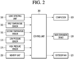
- FIG. 2 is a block diagram of a configuration of an air conditioner according to the first embodiment.
- the air conditioner 10 includes a compressor 100 configured to compress refrigerant.
- the compressor 100 includes an inverter compressor capable of adjusting an operating frequency.
- the air conditioner 10 includes a discharge pipe 101 provided in an outlet of the compressor 100 to guide a liquid of the refrigerant compressed by the compressor 100.
- the discharge pipe 101 may include a first temperature sensor 161 configured to detect a temperature of the refrigerant compressed by the compressor 100.
- the first temperature sensor 161 may be referred to as a "discharge temperature sensor.”
- a temperature value detected by the first temperature sensor 161 may be used to control an opening degree of a main expansion device 130.
- the air conditioner 10 may further include a high pressure sensor 175 disposed in the discharge pipe 101 to detect a pressure of the refrigerant compressed by the compressor 100, that is, a high pressure of the refrigeration cycle.
- the pressure value detected by the high pressure sensor 175 may be used to perform control according to a target high pressure in an air heating operation.
- the air conditioner 10 may further include a liquid changing valve 110 disposed in the discharge pipe 101 to change a liquid direction of the compressed refrigerant.
- the liquid changing valve 110 may include a four-way valve.
- the air conditioner 10 may include an outside heat exchanger 120 (outdoor and outside may be used synonymously herein) disposed in an outside unit and an inside heat exchanger 140 (indoor and inside may be used synonymously herein) disposed in an inside unit.
- the outside unit may be located outside and the inside unit may be located in an inside space.
- the refrigerant compressed by the compressor 100 is introduced into the outside heat exchanger 120 through the liquid changing valve 110.
- the refrigerant condensed by the outside heat exchanger 120 is decompressed by an inside expansion device (not illustrated) provided in the inside unit and is introduced into the inside heat exchanger 140.
- the refrigerant evaporated by the inside heat exchanger 140 is introduced into a gas liquid separator 150 through the liquid changing valve 110. Gas refrigerant separated by the gas liquid separator 150 is again sucked into the compressor 100.
- the refrigerant compressed by the compressor 100 flows into the inside heat exchanger 140 through the liquid changing valve 110.
- the refrigerant condensed by the inside heat exchanger 140 is decompressed by the main expansion device 130 and is introduced into the outside heat exchanger 120.
- the refrigerant evaporated by the outside heat exchanger 120 is introduced into the gas liquid separator 150 through the liquid changing valve 110. Gas refrigerant separated by the gas liquid separator 150 is again sucked into the compressor 100.
- the main expansion device 130 may be disposed in a pipe connecting the outside heat exchanger 120 and the inside heat exchanger 140.
- the main expansion device 130 may include an electronic expansion valve capable of adjusting an opening degree.
- the gas liquid separator 150 may be disposed on the side of a suction inlet of the compressor 100 to separate gas refrigerant from the evaporated refrigerant and provide the gas refrigerant to the compressor 100.
- the air conditioner 10 may further include an outside fan 125 disposed on one side of the outside heat exchanger 120 to provide air flow so as to allow external air to flow toward the outside heat exchanger 120.
- the air conditioner 10 may further include an inside fan 145 disposed on one side of the inside heat exchanger 140 to allow air in the inside space 5 to flow toward the inside heat exchanger 140.
- the air conditioner 10 may further include a second temperature sensor 165 that detects a temperature of the inside space 5. For example, a temperature value detected by the second temperature sensor 165 may be used to determine whether the temperature of the inside space 5 reaches a set temperature during the air cooling operation or the air heating operation of the air conditioner 10 to determine whether an inside load is resolved.
- the air conditioner 10 may further include a low pressure sensor 170 that detects a low pressure of the refrigeration cycle.
- the low pressure sensor 170 may be disposed in a path through which the evaporated refrigerant is sucked into the compressor 100.
- the low pressure sensor 170 may be disposed in a "low pressure pipe" extending from the gas liquid separator 150 to the compressor 100 to guide the gas refrigerant separated by the gas liquid separator 150 to the compressor 100.
- the air conditioner 10 further includes a load detecting unit 180 that detects a load of the inside space 5.
- the load of the inside space 5 may be determined based on information about the size of the inside space 5 or the thermal insulation of a building.
- the load detecting unit 180 includes a frequency detecting unit for detecting an operating frequency of the compressor 100.
- a required cycle pressure that is, a high pressure or a low pressure to be formed in a stable pressure range
- the operating frequency of the compressor 100 may be increased or decreased.
- the frequency detecting unit may detect the rate of change in the operating frequency of the compressor 100.
- the operating frequency of the compressor 100 may be controlled to be increased to more quickly achieve the required cycle pressure.
- a control may be performed to increase the increase rate of the operating frequency of the compressor 100 in order to decrease the low pressure of the refrigeration cycle.
- an inside load is determined as being large.
- the low pressure of the refrigeration cycle typically decreases and therefore, controls may be performed to decrease the operating frequency of the compressor 100 or decrease the increase rate thereof to maintain the low pressure or decrease the low pressure of the refrigeration cycle.
- the inside load is determined as being small.
- the load detecting unit includes a power detecting unit that detects current consumption or power consumption in the air conditioner 10.
- an inside load may be detected by using the current or power value detected through the current detecting unit or the power detecting unit.
- an increase rate of the current or power value is large, it may be recognized that the inside load is large.
- the increase rate of the current or power value is small, it may be recognized that the inside load is small.
- the air conditioner 10 further includes a control unit 200 configured to control an operation of the compressor 100, the main expansion device 130, and/or the outside fan 125 based on information detected by the load detecting unit 180, the first temperature sensor 161, the second temperature sensor 165, the low pressure sensor 170, and/or the high pressure sensor 175.
- a control unit 200 configured to control an operation of the compressor 100, the main expansion device 130, and/or the outside fan 125 based on information detected by the load detecting unit 180, the first temperature sensor 161, the second temperature sensor 165, the low pressure sensor 170, and/or the high pressure sensor 175.
- the control unit 200 may be electrically connected to the load detecting unit 180, the temperature sensors 161 and 165, the low pressure sensor 170, the high pressure sensor 175, the load detecting unit 180, the compressor 100, the main expansion device 130, and/or the outside fan 125.
- the air conditioner 10 may further include a memory unit 210 configured to store information about the operating frequency of the compressor 100 with respect to the operation modes of the air conditioner 10 in a mapping scheme.
- the memory unit 210 may store information about the opening degree of the main expansion device or information about the number of rotations of the outside fan 125, with respect to the operation modes of the air conditioner 10 in a mapping scheme.
- FIG. 3 is a flowchart of a method of controlling an air conditioner, according to the first embodiment.
- the compressor 100 When the air conditioner 10 is turned on, the compressor 100 is driven, and an air cooling operation or an air heating operation is initiated.
- the compressor 100 when the air conditioner 10 operates in the air heating operation mode, the compressor 100 may be controlled under what may be referred to as a "target high pressure control".
- the operating frequency of the compressor 100 may be determined such that the high pressure is formed in a set pressure range.
- the high pressure When the operating frequency of the compressor 100 increases, the high pressure may increase, and when the operating frequency of the compressor 100 decreases, the high pressure may decrease.
- an increase rate of the high pressure is less than a predetermined increase rate, and the operating frequency of the compressor 100 may increase.
- the increase rate of the high pressure is less than a predetermined increase rate in a case where the operating frequency of the compressor 100 increases, the increase rate of the operating frequency of the compressor 100 may increase over time. In this case, an increase rate of the power consumption or current consumption of the air conditioner 10 may be relatively high.
- an increase rate of the high pressure is greater than a predetermined increase rate, and the operating frequency of the compressor 100 may be maintained or decrease.
- the increase rate of the power consumption or current consumption of the air conditioner 10 may be relatively low.
- the compressor 100 when the air conditioner 10 operates in the air cooling operation mode, the compressor 100 may be controlled under what may be referred to as a "target low pressure control".
- target low pressure control since the low pressure of the refrigeration cycle impacts cooling performance, the operating frequency of the compressor 100 may be determined such that the low pressure is formed in a set pressure range.
- the low pressure may decrease, and when the operating frequency of the compressor 100 decreases, the low pressure may increase.
- a decrease rate of the low pressure is less than a predetermined decrease rate, and the operating frequency of the compressor 100 may increase.
- the increase rate of the operating frequency of the compressor 100 may increase over time.
- the increase rate of the power consumption or current consumption of the air conditioner 10 may be relatively high.
- the increase rate of the power consumption or current consumption of the air conditioner 10 may be relatively low (S11 and S12).
- the current load of the inside space is determined through the load detecting unit 180.
- the current load of the inside space is determined based on a rate of change in the operating frequency of the compressor 100 or an increase rate of the power consumption or current consumption of the air conditioner 10.
- the determined current load is compared with a reference load to determine a level of the current load.
- the reference load corresponds to a case where the increase rate of the operating frequency of the compressor 100 is a first set increase rate or a case where the increase rate of the power consumption or current consumption is a second set increase rate (S13 and S14).
- the determined current load is greater than or equal to the reference load, that is, when the increase rate of the operating frequency of the compressor 100 is greater than the first set increase rate, or when the increase rate of the power consumption or current consumption is greater than the second set increase rate, the determined current load is referred to as a "high load".
- the determined current load is less than the reference load, that is, when the increase rate of the operating frequency of the compressor 100 is less than the first set increase rate or the operating frequency of the compressor 100 is maintained or decreases, or when the increase rate of the power consumption or current consumption is less than the second set increase rate, the determined current load is referred to as a "low load".
- the air conditioner 10 may be controlled in different manners or control modes depending on whether the current load is determined as the "high load” or the "low load”.
- the air conditioner 10 when the current load is determined as the "high load", the air conditioner 10 may be controlled to operate in a "high load operation mode".
- Table 1 Mode Compressor Main expansion device Outside fan High load operation mode First operating frequency First set opening degree First set number of rotations
- the operating frequency of the compressor 100 may be set to the first operating frequency.
- the first operating frequency may be set to an operating frequency that is close to the maximum operating frequency of the compressor 100.
- the first operating frequency may be determined to be in a range from an operating frequency, which is 70% of the maximum operating frequency, to the maximum operating frequency.
- the opening degree of the main expansion device 130 may be set to a first set opening degree.
- the first set opening degree may be a relatively large opening degree as compared to when the air conditioner 10 is controlled to operate in the low load operation mode.
- the first set opening degree may be set to a full opening degree. Since the first set opening degree is set to the relatively large opening degree, the amount of the refrigerant circulating through the refrigeration cycle increases, thus improving air conditioning performance.
- the number of rotations of the outside fan 125 may be set to a first set number of rotations.
- the first set number of rotations may be a relatively large number of rotations as compared to when the air conditioner 10 is controlled to operate in the low load operation mode.
- the first set number of rotations may be set to the maximum number of rotations. Since the first set number of rotations is set to the relatively large number of rotations, the amount of heat exchanged in the outside heat exchanger increases, thus improving condensing performance or evaporation performance (S15, S16, and S17).
- the air conditioner 10 when the current load is determined as the "low load", the air conditioner 10 may be controlled to operate in a "low load operation mode".
- Table 2 Mode Compressor Main expansion device Outside fan Low load operation mode Second operating frequency Second set opening degree Second set number of rotations
- the operating frequency of the compressor 100 may be set to the second operating frequency.
- the second operating frequency is understood as being a frequency value less than the first operating frequency.
- the second operating frequency may be set to a value less than an operating frequency which is 70% of the maximum operating frequency.
- the opening degree of the main expansion device 130 may be set to the second set opening degree.
- the second set opening degree may be an opening degree less than the first set opening degree.
- the second set opening degree may be set to an opening degree that is in a range of 50 to 80% of the full opening degree. Since the second set opening degree is set to the relatively small opening degree as compared to when the air conditioner 10 is controlled to operate in the high load operation mode, the amount of the refrigerant circulating through the refrigeration cycle slightly decreases, thus achieving the operation optimized to the low load.
- the number of rotations of the outside fan 125 may be set to the second set number of rotations.
- the second set number of rotations may be less than the first set number of rotations.
- the second set number of rotations may be set to the number of rotations that is in a range of 50 to 70% of the maximum number of rotations. Since the second set number of rotations is set to the relatively small number of rotations, the outside heat exchanger may achieve heat exchange performance optimized to the low load (S18 and S19).
- the air conditioner 10 When the air conditioner 10 operates in the high load operation mode or the low load operation mode, it may be determined whether the temperature of the inside space reaches a set temperature.
- the temperature of the inside space may be detected by the second temperature sensor 165 (S20) .
- This operation mode may be referred to herein as a "temperature maintenance operation mode".
- control may be performed to decrease a frequency of the compressor in a case where the air conditioner 10 operates in the high load operation mode or the low load operation mode.
- the operating frequency of the compressor 100 may be set to a frequency that is 1/2 of the first operating frequency.
- the operating frequency of the compressor 100 may be set to a frequency that is 1/2 of the second operating frequency.
- the opening degree of the main expansion device 130 and the number of rotations of the outside fan 125 may be maintained (S21 and S22).
- control method it is possible to improve air cooling and air heating performance and prevent frequent thermo on/off by determining a load of the inside space through the load detecting unit and performing the high load operation mode and the low load operation mode based on the determined load of the inside space.
- the temperature of the inside space reaches the set temperature, it is possible to perform an operation of maintaining the temperature of the inside space by decreasing the frequency of the compressor 100, thus allowing a user to continuously feel comfortable.
- FIG. 4 is a flowchart of a method of controlling an air conditioner, according to a second embodiment. Since the second embodiment is different from the first embodiment in a partial configuration, a description will be given focusing on the difference and the same elements as the first embodiment quote the description and reference numerals of the first embodiment.
- the compressor 100 when the air conditioner 10 is turned on, the compressor 100 is driven and an air cooling operation or an air heating operation is initiated.
- the compressor 100 When the air conditioner 10 operates in an air heating operation mode, the compressor 100 is controlled under what is referred to as a "target high pressure control”.
- the compressor 100 When the air conditioner 10 operates in an air cooling operation mode, the compressor 100 is controlled under what is referred to as a "target low pressure control”.
- the current load of the inside space is determined through the load detecting unit 180. That is, the current load of the inside space may be determined based on a rate of change in the operating frequency of the compressor 100 or an increase rate of the power consumption or current consumption of the air conditioner 10. The determined current load may be compared with first and second reference loads.
- the first reference load may correspond to a case where the increase rate of the operating frequency of the compressor 100 is a first set increase rate or a case where the increase rate of the power consumption or current consumption is a second set increase rate.
- the second reference load may correspond to a case where the increase rate of the operating frequency of the compressor 100 is a third set increase rate or a case where the increase rate of the power consumption or current consumption is a fourth set increase rate.
- the third set increase rate may be lower than the first set increase rate, and the fourth set increase rate may be lower than the third set increase rate (S33 and S34).
- the determined current load When the determined current load is equal to or greater than the first reference load, that is, when the increase rate of the operating frequency of the compressor 100 is greater than the first set increase rate or when the increase rate of the power consumption or current consumption is greater than the second set increase rate, the determined current load may be referred to as a "high load".
- the determined current load when the determined current load is less than the second reference load, that is, when the increase rate of the operating frequency of the compressor 100 is less than the third set increase rate or the operating frequency of the compressor 100 remains the same or decreases or when the increase rate of the power consumption or current consumption is less than the fourth set increase rate, the determined current load may be referred to as a "low load".
- the determined current load when the determined current load is equal to or greater than the second reference load and is less than the first reference load, that is, when the increase rate of the operating frequency of the compressor 100 is equal to or greater than the third set increase rate and is less than the first set increase rate or when the increase rate of the power consumption or current consumption is equal to or greater than the fourth set increase rate and is less than the second set increase rate, the determined current load may be referred to as an "intermediate load".
- the air conditioner 10 may be controlled in different manners or control modes depending on whether the current load is determined as the "high load”, the "low load", or the "intermediate load”.
- the air conditioner 10 may be controlled to operate in a "high load operation mode", such as described above in Table 1.
- the first operating frequency of the compressor 100 is set to be equal to or higher than a value that is 70% of the maximum operating frequency
- the opening degree of the main expansion device 130 is set to a full opening degree
- the number of rotations of the outside fan 125 may be set to the maximum number of rotations.
- the air conditioner 10 may be controlled to operate in the "low load operation mode", such as described above in Table 2.
- the second operating frequency of the compressor 100 is set to be equal to or less than a value that is 40% of the maximum operating frequency
- the opening degree of the main expansion device 130 is set to be equal to or less than an opening degree that is 60% of the full opening degree
- the number of rotations of the outside fan 125 may be set to be equal to or less than a value that is 60% of the maximum number of rotations.
- the air conditioner 10 may be controlled to operate in a "general operation mode".
- the compressor 100 may be controlled to be driven at a third operating frequency, and the third operating frequency may be determined in a range of 40 to 70% of the maximum operating frequency.
- the opening degree of the main expansion device 130 may be determined in a range of 60 to 100% of the full opening degree and the number of rotations of the outside fan 125 may be determined in a range of 60 to 100% of the maximum number of rotations (S35 to S41).
- the air conditioner 10 When the air conditioner 10 operates in the high load operation mode, the low load operation mode, or the general operation mode, it is determined whether the temperature of the inside space reaches a set temperature.
- the temperature of the inside space may be detected by the second temperature sensor 165 (S42).
- This operation mode may be referred to as a "temperature maintenance operation mode".
- control may be performed to decrease a frequency of the compressor in a case where the air conditioner 10 operates in the high load operation mode, the low load operation mode, or the general operation mode.
- control may be performed to decrease the operating frequency of the compressor 100, which has been determined in each operation mode, by 1/2.
- the opening degree of the main expansion device 130 and the number of rotations of the outside fan 125 may be maintained (S43 and S44).
- control method it is possible to improve air cooling or heating performance and prevent frequent thermo on/off by determining a load of the inside space through the load detecting unit and performing the high load operation mode, the low load operation mode, or the general operation mode based on the determined load of the inside space.
- the temperature of the inside space reaches the set temperature, an operation of maintaining the temperature of the inside space by decreasing the frequency of the compressor 100 may be performed, thus allowing a user to continuously feel comfortable.
Landscapes
- Engineering & Computer Science (AREA)
- Mechanical Engineering (AREA)
- General Engineering & Computer Science (AREA)
- Chemical & Material Sciences (AREA)
- Combustion & Propulsion (AREA)
- Physics & Mathematics (AREA)
- Thermal Sciences (AREA)
- Life Sciences & Earth Sciences (AREA)
- Atmospheric Sciences (AREA)
- Signal Processing (AREA)
- Fuzzy Systems (AREA)
- Mathematical Physics (AREA)
- Sustainable Development (AREA)
- Air Conditioning Control Device (AREA)
- Human Computer Interaction (AREA)
Claims (9)
- Verfahren zum Steuern einer Klimaanlage (10), wobei das Verfahren die folgenden Schritte umfasst:Aktivieren (S11, S12; S31, S32) eines Kühlkreislaufs durch Antreiben eines Kompressors (100) mittels einer Steuerung (200);Detektieren durch einen Drucksensor (175, 170) eines hohen Drucks und eines niedrigen Drucks des Kühlkreislaufs, wenn der Kühlkreislauf aktiviert worden ist;Anpassen einer Betriebsfrequenz des Kompressors (100) durch die Steuerung (200) auf der Basis des detektierten hohen Drucks oder des detektierten niedrigen Drucks des Kühlkreislaufs;Feststellen (S13; S33) einer aktuellen Auslastung eines Innenraums (5) durch eine Auslastungsdetektionseinheit (180), wobei eine Auslastungsstufe des Innenraums (5) durch Vergleichen (S14, S15; S34, S35, S38) der aktuellen Auslastung mit einer Referenzauslastung festgestellt wird; undFeststellen (S17, S19; S37, S40, S42) der Betriebsfrequenz des Kompressors (100) durch die Auslastungsdetektionseinheit (180) auf der Basis der festgestellten Auslastungsstufe,wobei die Auslastungsdetektionseinheit (180) Folgendes umfasst:einen Frequenzdetektor, um die Betriebsfrequenz des Kompressors (100) zu detektieren, undeinen Energiedetektor, um den Stromverbrauch und den Energieverbrauch zu detektieren, die bei der Aktivierung des Kühlkreislaufs auftreten,wobei die Auslastungsstufe Folgendes umfasst:eine hohe Auslastung, bei der die aktuelle Auslastung größer oder gleich der Referenzauslastung ist; undeine niedrige Auslastung, bei der die aktuelle Auslastung niedriger als die Referenzauslastung ist,wobei die Referenzauslastung eine Auslastung ist, die einem Zustand entspricht, wenn eine Anstiegsrate der Betriebsfrequenz des Kompressors (100) einer ersten eingestellten Anstiegsrate entspricht, oder eine Auslastung ist, die einem Zustand entspricht, wenn eine Anstiegsrate des Energieverbrauchs oder des Stromverbrauchs einer zweiten eingestellten Anstiegsrate entspricht, undwobei dann, wenn festgestellt wird, dass die Anstiegsrate der Betriebsfrequenz des Kompressors (100) größer als die erste eingestellte Anstiegsrate ist, oder wenn die Anstiegsrate des Energieverbrauchs oder des Stromverbrauchs größer als die zweite eingestellte Anstiegsrate ist, die aktuelle Auslastung als die hohe Auslastung festgestellt wird.
- Verfahren nach Anspruch 1, wobei der hohe Druck und der niedrige Druck des Kühlkreislaufs detektiert werden, wenn der Kühlkreislauf aktiviert worden ist.
- Verfahren nach Anspruch 1, wobei dann, wenn festgestellt wird, dass die aktuelle Auslastung der hohen Auslastung entspricht, die Betriebsfrequenz des Kompressors (100) auf der Basis von Informationen, die der Betriebsfrequenz des Kompressors (100) zugeordnet sind, auf eine erste Betriebsfrequenz eingestellt wird.
- Verfahren nach Anspruch 3, wobei die erste Betriebsfrequenz die maximale Betriebsfrequenz des Kompressors (100) umfasst.
- Verfahren nach einem der Ansprüche 1 bis 4, das ferner das Feststellen eines Öffnungsgrads einer Hauptexpansionsvorrichtung (130) durch die Steuerung (200) auf der Basis der ermittelten Auslastungsstufe umfasst,
wobei dann, wenn festgestellt wird, dass die aktuelle Auslastung die hohe Auslastung ist, der Öffnungsgrad der Hauptexpansionsvorrichtung (130) auf einen vollständigen Öffnungsgrad eingestellt wird. - Verfahren nach einem der Ansprüche 1 bis 5, das ferner das Feststellen einer Drehzahl eines Außengebläses (125) auf der Basis der festgestellten Auslastungsstufe umfasst,
wobei dann, wenn festgestellt wird, dass die aktuelle Auslastung die hohe Auslastung ist, die Drehzahl des Außengebläses (125) auf die maximale Drehzahl eingestellt wird. - Verfahren nach einem der Ansprüche 1 bis 6, das ferner das Durchführen eines Betriebs zum Aufrechterhalten einer Temperatur durch die Steuerung (200) umfasst, um die Temperatur des Innenraums (5) aufrechtzuerhalten, wenn die Temperatur des Innenraums (5) eine eingestellte Temperatur erreicht hat.
- Verfahren nach Anspruch 7, wobei dann, wenn der Betrieb zum Aufrechterhalten der Temperatur ausgeführt wird, der Kompressor (100) mit einer Betriebsfrequenz angetrieben wird, die niedriger als die festgelegte Betriebsfrequenz des Kompressors (100) ist.
- Klimaanlage (10), die Folgendes umfasst:einen Kompressor (100) mit einer einstellbaren Betriebsfrequenz;einen äußeren Wärmetauscher (120), der Kühlmittel kondensiert, das durch den Kompressor (100) in einem Betrieb zum Kühlen von Luft komprimiert wird;eine Hauptexpansionsvorrichtung (130), die das Kühlmittel dekomprimiert, das durch den äußeren Wärmetauscher (120) kondensiert worden ist;einen Drucksensor (175, 170) zum Detektieren eines hohen Drucks und eines niedrigen Drucks des Kühlkreislaufs;einen inneren Wärmetauscher (140), der das Kühlmittel verdampft, das durch die Hauptexpansionsvorrichtung (130) dekomprimiert wurde, und Luft in einen Innenraum (5) abführt;eine Auslastungsdetektionseinheit (180), die eine Auslastung des Innenraums (5) detektiert, wobei die Auslastungsdetektionseinheit (180) eine Frequenzdetektionseinheit, die eine Änderungsrate der Betriebsfrequenz des Kompressors (100) detektiert, und eine Energiedetektionseinheit, die einen Stromverbrauch und einen Energieverbrauch detektiert, die bei einem Betrieb der Klimaanlage (10) auftreten, umfasst;eine Speichereinheit (210), die Informationen bezüglich der Betriebsfrequenz des Kompressors (100) speichert, wobei die gespeicherten Informationen der Auslastung zugeordnet werden, die durch die Auslastungsdetektionseinheit (180) detektiert wird; undeine Steuerung (200), die konfiguriert ist, eine Betriebsfrequenz des Kompressors (100) auf der Basis des detektierten hohen Drucks oder des detektierten niedrigen Drucks des Kühlkreislaufs einzustellen,wobei die Auslastungsdetektionseinheit (180) konfiguriert ist, eine aktuelle Auslastung des Innenraums (5) festzustellen, wobei eine Auslastungsstufe des Innenraums (5) durch Vergleichen (S14, S15; S34, S35, S38) der aktuellen Auslastung mit einer Referenzauslastung festgestellt wird,wobei die Auslastungsdetektionseinheit (180) konfiguriert ist, die Betriebsfrequenz des Kompressors (100) auf der Basis der festgestellten Auslastungsstufe festzulegen,wobei die Auslastungsstufe Folgendes umfasst:eine hohe Auslastung, bei der die aktuelle Auslastung größer oder gleich einer Referenzauslastung ist; undeine niedrige Auslastung, bei der die aktuelle Auslastung niedriger als die Referenzauslastung ist,wobei die Referenzauslastung eine Auslastung ist, die einem Zustand entspricht, wenn eine Anstiegsrate der Betriebsfrequenz des Kompressors (100) einer ersten eingestellten Anstiegsrate entspricht, oder eine Auslastung ist, die einem Zustand entspricht, wenn eine Anstiegsrate des Energieverbrauchs oder des Stromverbrauchs einer zweiten eingestellten Anstiegsrate entspricht, undwobei dann, wenn festgestellt wird, dass die Anstiegsrate der Betriebsfrequenz des Kompressors (100) größer als die erste eingestellte Anstiegsrate ist, oder wenn die Anstiegsrate des Energieverbrauchs oder des Stromverbrauchs größer als die zweite eingestellte Anstiegsrate ist, festgestellt wird, dass die aktuelle Auslastung der hohen Auslastung entspricht.
Applications Claiming Priority (1)
| Application Number | Priority Date | Filing Date | Title |
|---|---|---|---|
| KR1020160014108A KR102460483B1 (ko) | 2016-02-04 | 2016-02-04 | 인공지능 기능을 수반하는 공기 조화기 및 그 제어방법 |
Publications (2)
| Publication Number | Publication Date |
|---|---|
| EP3203166A1 EP3203166A1 (de) | 2017-08-09 |
| EP3203166B1 true EP3203166B1 (de) | 2020-09-02 |
Family
ID=57389311
Family Applications (1)
| Application Number | Title | Priority Date | Filing Date |
|---|---|---|---|
| EP16199986.7A Active EP3203166B1 (de) | 2016-02-04 | 2016-11-22 | Klimaanlage und verfahren zur steuerung davon |
Country Status (4)
| Country | Link |
|---|---|
| US (1) | US20170227272A1 (de) |
| EP (1) | EP3203166B1 (de) |
| KR (1) | KR102460483B1 (de) |
| CN (1) | CN107036230B (de) |
Families Citing this family (9)
| Publication number | Priority date | Publication date | Assignee | Title |
|---|---|---|---|---|
| CN108518806B (zh) * | 2018-05-21 | 2021-03-30 | 广东美的暖通设备有限公司 | 运行控制方法、装置、压缩机、空调器和可读存储介质 |
| CN108758965B (zh) * | 2018-06-19 | 2020-07-03 | 宁波奥克斯电气股份有限公司 | 一种过负荷保护控制方法、装置及空调 |
| KR102183484B1 (ko) * | 2018-09-18 | 2020-11-26 | 엘지전자 주식회사 | 인공지능을 이용하여 공조 부하를 예측하는 공기조화기, 클라우드 서버, 공기조화기의 구동방법 |
| KR102029250B1 (ko) * | 2018-10-02 | 2019-11-29 | 엘지전자 주식회사 | 인공지능에 기반하여 공조 부하를 예측하는 공기조화기, 클라우드 서버, 공기조화기의 구동방법 |
| JP6897652B2 (ja) * | 2018-10-31 | 2021-07-07 | ダイキン工業株式会社 | 空気調和機 |
| CN113375306B (zh) * | 2021-06-04 | 2022-10-28 | 青岛海尔空调器有限总公司 | 用于空调的控制方法及装置、空调 |
| DE102021213591A1 (de) * | 2021-12-01 | 2023-06-01 | BSH Hausgeräte GmbH | Kältegerät und Verfahren zum Betreiben eines Kältegeräts |
| GB2619730B (en) * | 2022-06-14 | 2024-07-24 | Sunswap Ltd | Control system for vapour compression cycle and related methods |
| CN116817419B (zh) * | 2023-06-26 | 2026-04-21 | 珠海格力电器股份有限公司 | 空调器的运行控制方法、运行控制装置和空调器 |
Family Cites Families (30)
| Publication number | Priority date | Publication date | Assignee | Title |
|---|---|---|---|---|
| JPS6196347A (ja) * | 1984-10-15 | 1986-05-15 | Sanyo Electric Co Ltd | 空気調和機 |
| JP2845981B2 (ja) * | 1989-09-19 | 1999-01-13 | 株式会社ゼクセル | 車両用空調装置 |
| US5301514A (en) * | 1992-12-02 | 1994-04-12 | General Electric Company | Low refrigerant charge detection by monitoring thermal expansion valve oscillation |
| JPH1193694A (ja) * | 1997-09-18 | 1999-04-06 | Toshiba Corp | ガスタービンプラント |
| US6244057B1 (en) * | 1998-09-08 | 2001-06-12 | Hitachi, Ltd. | Air conditioner |
| JP2002079828A (ja) * | 2000-09-07 | 2002-03-19 | Suzuki Motor Corp | 電気自動車用空調装置 |
| CN100398927C (zh) * | 2002-11-26 | 2008-07-02 | 乐金电子(天津)电器有限公司 | 空调的电力控制装置及方法 |
| KR100517600B1 (ko) * | 2002-12-05 | 2005-09-28 | 엘지전자 주식회사 | 공기조화기의 난방 운전 방법 |
| CN1247945C (zh) * | 2003-07-08 | 2006-03-29 | 浙江大学 | 低温热源热泵系统 |
| JP2005331203A (ja) * | 2004-05-21 | 2005-12-02 | Hitachi Ltd | 空気調和機 |
| JP2006266635A (ja) * | 2005-03-25 | 2006-10-05 | Saginomiya Seisakusho Inc | 冷却システム用制御装置 |
| KR20070017269A (ko) * | 2005-08-06 | 2007-02-09 | 삼성전자주식회사 | 멀티 에어컨시스템의 배관점검운전방법 및 배관점검방법 |
| JP2008030740A (ja) * | 2006-07-06 | 2008-02-14 | Denso Corp | 車両用冷凍サイクル装置 |
| KR100863303B1 (ko) * | 2007-02-07 | 2008-10-15 | 위니아만도 주식회사 | 에어컨 운전 제어 방법 |
| KR101488390B1 (ko) * | 2008-02-05 | 2015-01-30 | 엘지전자 주식회사 | 공기조화장치의 냉매량 판단 방법 |
| KR101622619B1 (ko) | 2009-07-23 | 2016-05-31 | 엘지전자 주식회사 | 공기조화기 및 그 운전 방법 |
| JP2011052873A (ja) * | 2009-08-31 | 2011-03-17 | Fujitsu General Ltd | ヒートポンプサイクル装置 |
| NZ601090A (en) * | 2009-12-08 | 2014-05-30 | Fusion Hvac Pty Ltd | A system and method for delivering air |
| US20110259041A1 (en) * | 2010-04-21 | 2011-10-27 | Whirlpool Corporation | High efficiency condenser |
| JP5132757B2 (ja) * | 2010-11-19 | 2013-01-30 | 三菱電機株式会社 | 制御装置、制御方法及びプログラム |
| JP2013011219A (ja) * | 2011-06-29 | 2013-01-17 | Panasonic Corp | 圧縮機の制御装置 |
| WO2013005260A1 (ja) * | 2011-07-07 | 2013-01-10 | 三菱電機株式会社 | 冷凍空調装置及び冷凍空調装置の制御方法 |
| JP2013088087A (ja) * | 2011-10-21 | 2013-05-13 | Hitachi Appliances Inc | 空気調和機 |
| JP5452659B2 (ja) * | 2012-05-16 | 2014-03-26 | 三菱電機株式会社 | 空気調和装置 |
| US9417638B2 (en) * | 2012-12-20 | 2016-08-16 | Automotive Research & Testing Center | Intelligent thermostatic control method and device for an air conditioner blowing cold and hot air |
| US10323862B2 (en) * | 2012-12-28 | 2019-06-18 | Mitsubishi Electric Corporation | Air conditioning unit having dynamic target condensing and evaporating values based on load requirements |
| CN103486692B (zh) * | 2013-09-17 | 2015-10-28 | 青岛海信日立空调系统有限公司 | 负荷自适应变频多联式热泵系统及控制压缩机频率的方法 |
| JP6327558B2 (ja) * | 2014-06-04 | 2018-05-23 | パナソニックIpマネジメント株式会社 | 空気調和装置 |
| JP6007965B2 (ja) * | 2014-12-15 | 2016-10-19 | ダイキン工業株式会社 | 空気調和装置 |
| CN104680340A (zh) * | 2015-03-30 | 2015-06-03 | 国家电网公司 | 配电网规划方法及系统 |
-
2016
- 2016-02-04 KR KR1020160014108A patent/KR102460483B1/ko active Active
- 2016-11-09 US US15/347,456 patent/US20170227272A1/en not_active Abandoned
- 2016-11-22 EP EP16199986.7A patent/EP3203166B1/de active Active
- 2016-12-23 CN CN201611206621.0A patent/CN107036230B/zh active Active
Non-Patent Citations (1)
| Title |
|---|
| None * |
Also Published As
| Publication number | Publication date |
|---|---|
| CN107036230B (zh) | 2022-04-15 |
| KR20170092879A (ko) | 2017-08-14 |
| EP3203166A1 (de) | 2017-08-09 |
| CN107036230A (zh) | 2017-08-11 |
| US20170227272A1 (en) | 2017-08-10 |
| KR102460483B1 (ko) | 2022-10-31 |
Similar Documents
| Publication | Publication Date | Title |
|---|---|---|
| EP3203166A1 (de) | Klimaanlage und verfahren zur steuerung davon | |
| JP5045524B2 (ja) | 冷凍装置 | |
| JP4613526B2 (ja) | 超臨界式ヒートポンプサイクル装置 | |
| EP2587193B1 (de) | Klimaanlage | |
| US10955160B2 (en) | Air conditioner including a plurality of utilization units connected in parallel to a heat source unit | |
| WO2008032559A1 (en) | Air conditioner | |
| US9726408B2 (en) | Air conditioner | |
| KR20100123729A (ko) | 냉동장치 | |
| KR20190115892A (ko) | 공기조화시스템의 제어방법 | |
| KR20170095616A (ko) | 공기 조화기 및 그 제어방법 | |
| JP2009243832A (ja) | 空気調和装置 | |
| EP1972861B1 (de) | Mehrzonenklimaanlage zum gleichzeitigen Heizen und Kühlen sowie Steuerverfahren dafür | |
| KR100798781B1 (ko) | 공기조화기의 운전제어방법 | |
| KR20080089967A (ko) | 공기조화기의 제어방법 | |
| JP7068537B1 (ja) | 空気調和装置および制御方法 | |
| KR101995583B1 (ko) | 공기조화기 및 그 제어방법 | |
| KR20140112681A (ko) | 공기 조화기의 제어방법 | |
| JP6049324B2 (ja) | 空気調和機 | |
| KR101153422B1 (ko) | 에어컨 운전 제어 방법 | |
| KR20140091794A (ko) | 공기 조화기 및 그 제어 방법 | |
| KR101622619B1 (ko) | 공기조화기 및 그 운전 방법 | |
| JP2023100176A (ja) | 空気調和機 | |
| KR100304553B1 (ko) | 히트펌프공기조화기와그난방운전을위한제어방법 | |
| KR102339547B1 (ko) | 공기조화기의 제어방법 | |
| CN112283897A (zh) | 一种空调器及控制方法 |
Legal Events
| Date | Code | Title | Description |
|---|---|---|---|
| PUAI | Public reference made under article 153(3) epc to a published international application that has entered the european phase |
Free format text: ORIGINAL CODE: 0009012 |
|
| STAA | Information on the status of an ep patent application or granted ep patent |
Free format text: STATUS: THE APPLICATION HAS BEEN PUBLISHED |
|
| AK | Designated contracting states |
Kind code of ref document: A1 Designated state(s): AL AT BE BG CH CY CZ DE DK EE ES FI FR GB GR HR HU IE IS IT LI LT LU LV MC MK MT NL NO PL PT RO RS SE SI SK SM TR |
|
| AX | Request for extension of the european patent |
Extension state: BA ME |
|
| STAA | Information on the status of an ep patent application or granted ep patent |
Free format text: STATUS: REQUEST FOR EXAMINATION WAS MADE |
|
| 17P | Request for examination filed |
Effective date: 20170925 |
|
| RBV | Designated contracting states (corrected) |
Designated state(s): AL AT BE BG CH CY CZ DE DK EE ES FI FR GB GR HR HU IE IS IT LI LT LU LV MC MK MT NL NO PL PT RO RS SE SI SK SM TR |
|
| GRAP | Despatch of communication of intention to grant a patent |
Free format text: ORIGINAL CODE: EPIDOSNIGR1 |
|
| STAA | Information on the status of an ep patent application or granted ep patent |
Free format text: STATUS: GRANT OF PATENT IS INTENDED |
|
| INTG | Intention to grant announced |
Effective date: 20200428 |
|
| GRAS | Grant fee paid |
Free format text: ORIGINAL CODE: EPIDOSNIGR3 |
|
| GRAA | (expected) grant |
Free format text: ORIGINAL CODE: 0009210 |
|
| STAA | Information on the status of an ep patent application or granted ep patent |
Free format text: STATUS: THE PATENT HAS BEEN GRANTED |
|
| AK | Designated contracting states |
Kind code of ref document: B1 Designated state(s): AL AT BE BG CH CY CZ DE DK EE ES FI FR GB GR HR HU IE IS IT LI LT LU LV MC MK MT NL NO PL PT RO RS SE SI SK SM TR |
|
| REG | Reference to a national code |
Ref country code: GB Ref legal event code: FG4D |
|
| REG | Reference to a national code |
Ref country code: AT Ref legal event code: REF Ref document number: 1309305 Country of ref document: AT Kind code of ref document: T Effective date: 20200915 Ref country code: CH Ref legal event code: EP |
|
| REG | Reference to a national code |
Ref country code: DE Ref legal event code: R096 Ref document number: 602016043104 Country of ref document: DE |
|
| REG | Reference to a national code |
Ref country code: IE Ref legal event code: FG4D |
|
| REG | Reference to a national code |
Ref country code: LT Ref legal event code: MG4D |
|
| PG25 | Lapsed in a contracting state [announced via postgrant information from national office to epo] |
Ref country code: HR Free format text: LAPSE BECAUSE OF FAILURE TO SUBMIT A TRANSLATION OF THE DESCRIPTION OR TO PAY THE FEE WITHIN THE PRESCRIBED TIME-LIMIT Effective date: 20200902 Ref country code: BG Free format text: LAPSE BECAUSE OF FAILURE TO SUBMIT A TRANSLATION OF THE DESCRIPTION OR TO PAY THE FEE WITHIN THE PRESCRIBED TIME-LIMIT Effective date: 20201202 Ref country code: LT Free format text: LAPSE BECAUSE OF FAILURE TO SUBMIT A TRANSLATION OF THE DESCRIPTION OR TO PAY THE FEE WITHIN THE PRESCRIBED TIME-LIMIT Effective date: 20200902 Ref country code: NO Free format text: LAPSE BECAUSE OF FAILURE TO SUBMIT A TRANSLATION OF THE DESCRIPTION OR TO PAY THE FEE WITHIN THE PRESCRIBED TIME-LIMIT Effective date: 20201202 Ref country code: SE Free format text: LAPSE BECAUSE OF FAILURE TO SUBMIT A TRANSLATION OF THE DESCRIPTION OR TO PAY THE FEE WITHIN THE PRESCRIBED TIME-LIMIT Effective date: 20200902 Ref country code: GR Free format text: LAPSE BECAUSE OF FAILURE TO SUBMIT A TRANSLATION OF THE DESCRIPTION OR TO PAY THE FEE WITHIN THE PRESCRIBED TIME-LIMIT Effective date: 20201203 Ref country code: FI Free format text: LAPSE BECAUSE OF FAILURE TO SUBMIT A TRANSLATION OF THE DESCRIPTION OR TO PAY THE FEE WITHIN THE PRESCRIBED TIME-LIMIT Effective date: 20200902 |
|
| REG | Reference to a national code |
Ref country code: NL Ref legal event code: MP Effective date: 20200902 |
|
| REG | Reference to a national code |
Ref country code: AT Ref legal event code: MK05 Ref document number: 1309305 Country of ref document: AT Kind code of ref document: T Effective date: 20200902 |
|
| PG25 | Lapsed in a contracting state [announced via postgrant information from national office to epo] |
Ref country code: PL Free format text: LAPSE BECAUSE OF FAILURE TO SUBMIT A TRANSLATION OF THE DESCRIPTION OR TO PAY THE FEE WITHIN THE PRESCRIBED TIME-LIMIT Effective date: 20200902 Ref country code: LV Free format text: LAPSE BECAUSE OF FAILURE TO SUBMIT A TRANSLATION OF THE DESCRIPTION OR TO PAY THE FEE WITHIN THE PRESCRIBED TIME-LIMIT Effective date: 20200902 Ref country code: RS Free format text: LAPSE BECAUSE OF FAILURE TO SUBMIT A TRANSLATION OF THE DESCRIPTION OR TO PAY THE FEE WITHIN THE PRESCRIBED TIME-LIMIT Effective date: 20200902 |
|
| PG25 | Lapsed in a contracting state [announced via postgrant information from national office to epo] |
Ref country code: RO Free format text: LAPSE BECAUSE OF FAILURE TO SUBMIT A TRANSLATION OF THE DESCRIPTION OR TO PAY THE FEE WITHIN THE PRESCRIBED TIME-LIMIT Effective date: 20200902 Ref country code: PT Free format text: LAPSE BECAUSE OF FAILURE TO SUBMIT A TRANSLATION OF THE DESCRIPTION OR TO PAY THE FEE WITHIN THE PRESCRIBED TIME-LIMIT Effective date: 20210104 Ref country code: SM Free format text: LAPSE BECAUSE OF FAILURE TO SUBMIT A TRANSLATION OF THE DESCRIPTION OR TO PAY THE FEE WITHIN THE PRESCRIBED TIME-LIMIT Effective date: 20200902 Ref country code: CZ Free format text: LAPSE BECAUSE OF FAILURE TO SUBMIT A TRANSLATION OF THE DESCRIPTION OR TO PAY THE FEE WITHIN THE PRESCRIBED TIME-LIMIT Effective date: 20200902 Ref country code: EE Free format text: LAPSE BECAUSE OF FAILURE TO SUBMIT A TRANSLATION OF THE DESCRIPTION OR TO PAY THE FEE WITHIN THE PRESCRIBED TIME-LIMIT Effective date: 20200902 |
|
| PG25 | Lapsed in a contracting state [announced via postgrant information from national office to epo] |
Ref country code: AL Free format text: LAPSE BECAUSE OF FAILURE TO SUBMIT A TRANSLATION OF THE DESCRIPTION OR TO PAY THE FEE WITHIN THE PRESCRIBED TIME-LIMIT Effective date: 20200902 Ref country code: AT Free format text: LAPSE BECAUSE OF FAILURE TO SUBMIT A TRANSLATION OF THE DESCRIPTION OR TO PAY THE FEE WITHIN THE PRESCRIBED TIME-LIMIT Effective date: 20200902 Ref country code: ES Free format text: LAPSE BECAUSE OF FAILURE TO SUBMIT A TRANSLATION OF THE DESCRIPTION OR TO PAY THE FEE WITHIN THE PRESCRIBED TIME-LIMIT Effective date: 20200902 Ref country code: IS Free format text: LAPSE BECAUSE OF FAILURE TO SUBMIT A TRANSLATION OF THE DESCRIPTION OR TO PAY THE FEE WITHIN THE PRESCRIBED TIME-LIMIT Effective date: 20210102 |
|
| REG | Reference to a national code |
Ref country code: DE Ref legal event code: R097 Ref document number: 602016043104 Country of ref document: DE |
|
| PG25 | Lapsed in a contracting state [announced via postgrant information from national office to epo] |
Ref country code: SK Free format text: LAPSE BECAUSE OF FAILURE TO SUBMIT A TRANSLATION OF THE DESCRIPTION OR TO PAY THE FEE WITHIN THE PRESCRIBED TIME-LIMIT Effective date: 20200902 Ref country code: MC Free format text: LAPSE BECAUSE OF FAILURE TO SUBMIT A TRANSLATION OF THE DESCRIPTION OR TO PAY THE FEE WITHIN THE PRESCRIBED TIME-LIMIT Effective date: 20200902 |
|
| REG | Reference to a national code |
Ref country code: CH Ref legal event code: PL |
|
| PLBE | No opposition filed within time limit |
Free format text: ORIGINAL CODE: 0009261 |
|
| STAA | Information on the status of an ep patent application or granted ep patent |
Free format text: STATUS: NO OPPOSITION FILED WITHIN TIME LIMIT |
|
| PG25 | Lapsed in a contracting state [announced via postgrant information from national office to epo] |
Ref country code: LU Free format text: LAPSE BECAUSE OF NON-PAYMENT OF DUE FEES Effective date: 20201122 |
|
| 26N | No opposition filed |
Effective date: 20210603 |
|
| REG | Reference to a national code |
Ref country code: BE Ref legal event code: MM Effective date: 20201130 |
|
| GBPC | Gb: european patent ceased through non-payment of renewal fee |
Effective date: 20201202 |
|
| PG25 | Lapsed in a contracting state [announced via postgrant information from national office to epo] |
Ref country code: CH Free format text: LAPSE BECAUSE OF NON-PAYMENT OF DUE FEES Effective date: 20201130 Ref country code: DK Free format text: LAPSE BECAUSE OF FAILURE TO SUBMIT A TRANSLATION OF THE DESCRIPTION OR TO PAY THE FEE WITHIN THE PRESCRIBED TIME-LIMIT Effective date: 20200902 Ref country code: SI Free format text: LAPSE BECAUSE OF FAILURE TO SUBMIT A TRANSLATION OF THE DESCRIPTION OR TO PAY THE FEE WITHIN THE PRESCRIBED TIME-LIMIT Effective date: 20200902 Ref country code: LI Free format text: LAPSE BECAUSE OF NON-PAYMENT OF DUE FEES Effective date: 20201130 |
|
| PG25 | Lapsed in a contracting state [announced via postgrant information from national office to epo] |
Ref country code: FR Free format text: LAPSE BECAUSE OF NON-PAYMENT OF DUE FEES Effective date: 20201130 Ref country code: IE Free format text: LAPSE BECAUSE OF NON-PAYMENT OF DUE FEES Effective date: 20201122 |
|
| PG25 | Lapsed in a contracting state [announced via postgrant information from national office to epo] |
Ref country code: GB Free format text: LAPSE BECAUSE OF NON-PAYMENT OF DUE FEES Effective date: 20201202 |
|
| PG25 | Lapsed in a contracting state [announced via postgrant information from national office to epo] |
Ref country code: IS Free format text: LAPSE BECAUSE OF FAILURE TO SUBMIT A TRANSLATION OF THE DESCRIPTION OR TO PAY THE FEE WITHIN THE PRESCRIBED TIME-LIMIT Effective date: 20210102 Ref country code: TR Free format text: LAPSE BECAUSE OF FAILURE TO SUBMIT A TRANSLATION OF THE DESCRIPTION OR TO PAY THE FEE WITHIN THE PRESCRIBED TIME-LIMIT Effective date: 20200902 Ref country code: MT Free format text: LAPSE BECAUSE OF FAILURE TO SUBMIT A TRANSLATION OF THE DESCRIPTION OR TO PAY THE FEE WITHIN THE PRESCRIBED TIME-LIMIT Effective date: 20200902 Ref country code: CY Free format text: LAPSE BECAUSE OF FAILURE TO SUBMIT A TRANSLATION OF THE DESCRIPTION OR TO PAY THE FEE WITHIN THE PRESCRIBED TIME-LIMIT Effective date: 20200902 |
|
| PG25 | Lapsed in a contracting state [announced via postgrant information from national office to epo] |
Ref country code: MK Free format text: LAPSE BECAUSE OF FAILURE TO SUBMIT A TRANSLATION OF THE DESCRIPTION OR TO PAY THE FEE WITHIN THE PRESCRIBED TIME-LIMIT Effective date: 20200902 |
|
| PG25 | Lapsed in a contracting state [announced via postgrant information from national office to epo] |
Ref country code: BE Free format text: LAPSE BECAUSE OF NON-PAYMENT OF DUE FEES Effective date: 20201130 |
|
| PG25 | Lapsed in a contracting state [announced via postgrant information from national office to epo] |
Ref country code: NL Free format text: LAPSE BECAUSE OF NON-PAYMENT OF DUE FEES Effective date: 20200923 |
|
| PGFP | Annual fee paid to national office [announced via postgrant information from national office to epo] |
Ref country code: DE Payment date: 20241007 Year of fee payment: 9 |
|
| PGFP | Annual fee paid to national office [announced via postgrant information from national office to epo] |
Ref country code: IT Payment date: 20241008 Year of fee payment: 9 |