EP3199715A2 - Trop-plein pour un bac, en particulier évier - Google Patents
Trop-plein pour un bac, en particulier évier Download PDFInfo
- Publication number
- EP3199715A2 EP3199715A2 EP16197956.2A EP16197956A EP3199715A2 EP 3199715 A2 EP3199715 A2 EP 3199715A2 EP 16197956 A EP16197956 A EP 16197956A EP 3199715 A2 EP3199715 A2 EP 3199715A2
- Authority
- EP
- European Patent Office
- Prior art keywords
- overflow
- sink
- flow channel
- section
- opening
- Prior art date
- Legal status (The legal status is an assumption and is not a legal conclusion. Google has not performed a legal analysis and makes no representation as to the accuracy of the status listed.)
- Granted
Links
Images
Classifications
-
- E—FIXED CONSTRUCTIONS
- E03—WATER SUPPLY; SEWERAGE
- E03C—DOMESTIC PLUMBING INSTALLATIONS FOR FRESH WATER OR WASTE WATER; SINKS
- E03C1/00—Domestic plumbing installations for fresh water or waste water; Sinks
- E03C1/12—Plumbing installations for waste water; Basins or fountains connected thereto; Sinks
- E03C1/22—Outlet devices mounted in basins, baths, or sinks
- E03C1/23—Outlet devices mounted in basins, baths, or sinks with mechanical closure mechanisms
- E03C1/232—Outlet devices mounted in basins, baths, or sinks with mechanical closure mechanisms combined with overflow devices
-
- E—FIXED CONSTRUCTIONS
- E03—WATER SUPPLY; SEWERAGE
- E03C—DOMESTIC PLUMBING INSTALLATIONS FOR FRESH WATER OR WASTE WATER; SINKS
- E03C1/00—Domestic plumbing installations for fresh water or waste water; Sinks
- E03C1/12—Plumbing installations for waste water; Basins or fountains connected thereto; Sinks
- E03C1/24—Overflow devices for basins or baths
-
- E—FIXED CONSTRUCTIONS
- E03—WATER SUPPLY; SEWERAGE
- E03C—DOMESTIC PLUMBING INSTALLATIONS FOR FRESH WATER OR WASTE WATER; SINKS
- E03C1/00—Domestic plumbing installations for fresh water or waste water; Sinks
- E03C1/12—Plumbing installations for waste water; Basins or fountains connected thereto; Sinks
- E03C1/18—Sinks, whether or not connected to the waste-pipe
-
- E—FIXED CONSTRUCTIONS
- E03—WATER SUPPLY; SEWERAGE
- E03C—DOMESTIC PLUMBING INSTALLATIONS FOR FRESH WATER OR WASTE WATER; SINKS
- E03C1/00—Domestic plumbing installations for fresh water or waste water; Sinks
- E03C1/12—Plumbing installations for waste water; Basins or fountains connected thereto; Sinks
- E03C1/24—Overflow devices for basins or baths
- E03C1/244—Separate devices to be placed on the outlet opening
Definitions
- the invention relates to an overflow for a sink according to the preamble of claim 1, with at least one inlet opening, which is intended for mounting on a sink of the sink or on an overflow well or a separate spout, and with an outlet opening for mounting on a Drain or vent valve of the basin or the sink is determined, wherein between the inlet opening and outlet opening a flow channel for a fluid or water is arranged.
- the invention also relates to a sink with at least one overflow, which sink comprises an opening in a side wall of a sink or an opening in a horizontal surface of the sink, preferably in the region of an overflow well or a separate spout, which opening fluidly with an overflow Drain of the sink is connected, according to the preamble of claim 13.
- the invention relates to a retrofit element for such a sink with overflow, which retrofit element is adapted to be fitted into the existing overflow of the sink.
- Rinsing known type especially kitchen sinks, regularly have an overflow, as defined above, so that at a closure of the actual rinse cycle excess water from the sink or an overflow tray can run when the water level has reached a certain level or if water in the overflow trough or reaches the spout, eg from a drainer of the sink. This should avoid flooding and corresponding damage.
- the invention has for its object to provide an improved overflow in a simple and cost-effective manner, so that from the basin and / or the overflow trough or the separate spout overflowing water can be optimally and safely dissipated.
- this solution should be retrofitted even with existing sinks without major construction effort (retrofitted).
- an overflow for a sink preferably a kitchen sink with at least one sink and an overflow well or a separate spout, with at least one inlet opening, which is intended for mounting on the basin or on the overflow well or the separate spout, and with an outlet opening , which is intended for mounting on a drain or vent valve of the sink or the basin, wherein between the inlet opening and outlet opening a flow channel for a fluid is arranged, characterized in that in the flow channel at least a portion (flow channel section) is provided in the flow channel has a substantially circular cross-section.
- the overflow may in particular also have two or more inlet openings, one of which is present on the basin and another on the overflow recess or the separate spout or a further basin if so mounted or mountable.
- the realization of several separate inventive overflows is possible, for example, for each sink or sink sink and overflow trough or spout.
- a sink according to the invention with at least one overflow which sink comprises an opening in a side wall of a sink or an opening in a horizontal surface of the sink, preferably in the region of an overflow well or a separate spout, which opening via a Overflow fluidly connected to a drain of the sink, characterized in that the sink has an overflow according to the invention or a further development thereof.
- the invention provides a retrofit element for a sink with overflow, which sink comprises an opening in a side wall of a sink or an opening in a horizontal surface of the sink, preferably in the region of an overflow trough or a separate spout, which opening fluidly with the overflow an outlet of the sink is connected, which retrofit element is adapted to be fitted into the overflow, wherein an outer contour of the retrofit element substantially corresponds to an inner contour of the overflow in a region, and wherein the retrofit element has at least one opening, the inner contour of a substantially has circular cross-section.
- At least one section is provided in the flow channel defined between the at least one inlet opening and the outlet opening of the overflow, in which the flow channel has a substantially circular cross section, even if the flow channel itself - which is the rule - a thereof has a different cross-sectional geometry.
- Said flow channel section of circular cross-section as fluid drains through the weir, provides vortex formation similar to that of an upturned bottle when set in motion about its longitudinal axis.
- This has a particularly beneficial effect, especially with overflow wells and separate spouts, because a back pressure can not really build up in this arrangement.
- the flow channel has a constant cross section in the section, which can have a positive effect on the vortex formation. This can apply to at least a major part of the mentioned section.
- the flow channel has at least one, for example conical, taper in its cross section in the section, viewed in the flow direction of the fluid. This may for example be the case in the region of the inlet opening.
- the flow channel in the section can also have an extension of its cross section, preferably in the region or in the direction of the outlet opening.
- the section has a certain length L, which may be numerically linked to a diameter D of the section.
- L f ⁇ D.
- another embodiment of the overflow according to the invention provides that a sum of the cross sections of the sections, if several such sections are present, or the cross sections of the one existing section in the range of about 175 mm 2 , most preferably between about 150 mm 2 and about 200 mm 2 .
- the overflow provides that the (several) sections are arranged next to one another, on a line, in the manner of a triangle, offset in zigzag or in another relative position to one another , preferably in each case based on the location of their centers.
- the at least one section or at least one of the plurality of sections may be arranged in the region of the inlet opening of the overflow, for example in the region of a so-called overflow head.
- the overflow head is that part of the overflow which is physically mounted directly in the region of an overflow opening of the sink or of the sink at this or on this. The same applies to the inlet opening in the region of an overflow trough or a separate spout.
- the at least one section or one of the several sections is arranged in the region of the outlet opening of the overflow, that is to say rather in the direction of the rinsing outlet.
- the circular flow channel section can also be arranged at any other point of the overflow or the overflow flow channel.
- the at least one section or at least one of the plurality of sections is arranged in the region of an elbow of the flow channel, which angle piece a first, when mounted vertical portion of the flow channel in a second, horizontal in assembly section the flow channel transferred.
- the at least one flow channel section may be arranged in the region of the first section (ie vertically) and / or in the region of the second section (ie horizontally).
- the retrofit element is designed to be fitted into an existing overflow.
- an outer contour of the retrofit element substantially correspond to an inner contour of the overflow in a region.
- the retrofit element can be used inside, as a kind of use, in an existing overflow. This can basically be done at any point of the overflow, so for example in the overflow head.
- the above mentioned can be Overflow head, if this includes the said circular flow channel section, even consider themselves as a retrofit element, because he can replace an existing overflow head of an existing overflow.
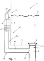
- FIG. 1 is a schematic and partially in section a sink, in particular a kitchen sink, shown, which is generally designated by the reference numeral 1.
- the sink 1 comprises at least one sink 2, of which only a lower corner area is shown, which comprises a pool wall 3 and a pool floor 4.
- a drain opening is provided at the reference numeral 5, which fluidly communicates with a sink drain 6, which is known per se.
- a sealing plug or valve plug 7 is arranged, which closes the drain opening 5 in a fluid-tight manner in the exemplary embodiment shown, so that no water can flow out of the sink basin 2 through the drain opening 5.
- flushing water 2 is contained in the sink tank 2 up to a water level 9 shown schematically.
- the water level 9 is at the height of an opening 10 in the pool wall 3, which opening 10 can also be referred to as an overflow opening. Due to the selected representation, the opening 10 in Figure 1 is not visible.
- the so-called overflow head 11 of a known overflow 12 is mounted on the outside of the pool wall 3, via which overflow 12 water 8 can flow from the sink 2 to the sink drain 6, when the water level 9 within the sink 2 a certain level reaches or exceeds.
- the overflow 12 comprises, in addition to the already mentioned overflow head 11, an inlet opening 13 in the region of the overflow head 11, which inlet opening 13 communicates with the aforementioned opening 10 in the basin wall 3 of the sink 2.
- Around the inlet opening 13 around a seal is regularly arranged to seal the overflow head 11 fluid-tight against the pool wall 3. This seal is in FIG. 1 not visible.
- At the overflow head 11 closes according to FIG.
- overflow pipe 14 which defines an outlet opening 15 at its end facing away from the overflow head 11, via which the overflow 12 opens into the flushing outlet 6.
- Inlet opening 13, overflow head 11, overflow pipe 14 and outlet opening 15 define in this way a flow channel 14a from the opening 10 in the pool wall 3 of the sink 2 to the sink 6, so that water 8 can flow from the sink 2 through the overflow 12 when the water level 9 - as already stated was - reaches or exceeds a certain level (a certain level).
- FIG. 1 The so far by means of FIG. 1 described embodiment is known per se and comes in commercial (kitchen) sinks, such as the sink 1 shown, used regularly.
- the present invention now relates to improvements in the area of the overflow 12, in particular of the overflow head 11, which will be discussed in more detail with reference to the following figures.
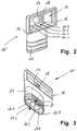
- FIG. 2 shows in perspective overall view of an overflow head 11 of an overflow according to the invention, the in FIG. 2 not shown.
- the overflow head 11 ' also includes the already mentioned, approximately rectangular inlet opening 13, which is surrounded by a correspondingly shaped sealing surface 16.
- Approximately in the center of the otherwise slightly funnel-shaped inwardly tapering inlet opening 13 is centrally approximately circular-cylindrical reinforced structure 17 which has a mounting hole 18 for attachment of the overflow head 11 in the region of the pool wall 3 (see. FIG. 1 ) trains.
- In a lower boundary surface 19 of the inlet opening 13 four openings or holes 20.1 to 20.4 are present side by side in a row, which extend parallel to each other through a connecting piece 21 of the overflow head 11. These openings or holes 20.1 to 20.4 each define a flow channel section of the overflow 12 (see. FIG.
- the connecting piece 21 of the overflow head 11 has on the outside protruding formations, which can serve for the attachment of a deferred tube or hose (not shown) or for reinforcing purposes.
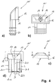
- FIG. 3 shows the overflow head 11 in a further perspective view obliquely from below, so that the formation and arrangement of the openings / holes or flow channel sections 20.1 to 20.4 can be clearly seen.
- These are - as already stated - side by side on a line (relative to their virtual centers, not shown) and each have approximately the same diameter D.
- the invention is by no means limited to the arrangement, number or size configuration of the openings / bores 20.1 to 20.4 shown here.
- the apertures / bores 20.1 - 20.4 may also have different diameters D, and there may be more or less than the four apertures / holes 20.1 - 20.4 shown.
- these may be arranged relative to each other in a different geometry, for example offset, in zigzag, in the manner of a square, triangle or the like, or, for example, only a single such breakthrough may be present. It is essential in any case that the opening or the openings have or have an approximately circular diameter, although the connecting piece 21 of the overflow head 11 or its inlet opening 13 has a deviating geometry (oval or rectangular). Applicant has found that the presence of circular flow channel sections significantly improves the overflow water flow behavior in the overflow area, comparable to the improved leakage of water from an over-the-top bottle as it rotates about the longitudinal axis of the bottle becomes.
- the openings / bores 20.1 - 20.4 can have a terminal widening in the region of the inlet opening 13 and / or in the area of a free (lower) end of the connecting piece 21, as in FIG FIG. 3 at reference 22.4 for the bore 20.4 is shown as an example.
- FIG. 4 shows further views of the overflow head 11 'according to the FIGS. 2 and 3 .
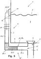
- FIG. 5 schematically shows an alternative embodiment of the overflow according to the invention (in FIG. 5 denoted by reference numeral 12 '), in which, alternatively or in addition to the flow channel sections with a circular cross section formed in the region of the overflow head 11, 11', a (further) such flow channel section is provided in the region of the overflow pipe 14.
- said further flow channel section is designated by reference numeral 20.5 and arranged in the region of an angle 14.1, which connects a first pipe part 14.2, which is connected in extension thereof to the connecting piece 21 of the overflow head 11, 11 ', with a second pipe part 14.3, which is connected to the sink outlet 6 and defines the outlet opening 15 of the overflow 12 '.
- the elbow or angle part 14.1 is in FIG. 5 hatched shown.
- the at least one flow channel section 20.5 could alternatively also be arranged in the region of the first pipe part 14.2 and / or of the second pipe part 14.3.
- the present proposed improvement in the field of (scavenging) overflow can also be realized by retrofitting an already existing overflow in an existing sink, for example by a corresponding pipe or elbow 14.1 - 14.3 installed later or a corresponding use is used in an existing overflow.
- the same also applies to the overflow head 11 ', which can replace an existing, known overflow head 11.
- said diameter D of the openings / holes in the range of 2 to 35 mm, with smaller diameters D a corresponding plurality of openings is to be provided.
- a minimum cross-section summed over all apertures or bores should be in the range of about 150 mm 2 to about 200 mm 2 , preferably about 175 mm 2 .
- the invention is not limited to the application in the area of a sink, but it can alternatively or additionally be used in the area of a so-called. Overflow well or a separate spout.
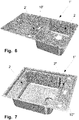
- FIG. 6 shows a flushing 1 'with overflow well 2'.
- This overflow well 2 ' has a (in the installed state) horizontally disposed opening 10', below which an inventive overflow (not shown here) is mounted or mounted to make its benefits for such flushing 1 'usable.
- FIG. 7 shows a rinse 1 "with a separate spout 2".
- This spout 2 " also has a (in the installed state) horizontally disposed opening 10", below which an inventive overflow (not shown here) is mounted or mounted to make its benefits even for such rinsing 1 "usable.
- an inventive overflow in the sinks 1 ', 1 "according to FIG. 6 or 7 additionally be provided in the area of the basin 2, as described above.
Applications Claiming Priority (1)
| Application Number | Priority Date | Filing Date | Title |
|---|---|---|---|
| DE102016100338.7A DE102016100338A1 (de) | 2016-01-11 | 2016-01-11 | Überlauf für ein Becken, insbesondere Spülenbecken |
Publications (3)
| Publication Number | Publication Date |
|---|---|
| EP3199715A2 true EP3199715A2 (fr) | 2017-08-02 |
| EP3199715A3 EP3199715A3 (fr) | 2017-10-18 |
| EP3199715B1 EP3199715B1 (fr) | 2020-03-25 |
Family
ID=57286283
Family Applications (1)
| Application Number | Title | Priority Date | Filing Date |
|---|---|---|---|
| EP16197956.2A Active EP3199715B1 (fr) | 2016-01-11 | 2016-11-09 | Trop-plein pour un bac, en particulier évier |
Country Status (4)
| Country | Link |
|---|---|
| EP (1) | EP3199715B1 (fr) |
| CN (1) | CN106958274B (fr) |
| CH (1) | CH711775B1 (fr) |
| DE (1) | DE102016100338A1 (fr) |
Cited By (1)
| Publication number | Priority date | Publication date | Assignee | Title |
|---|---|---|---|---|
| KR20200044938A (ko) * | 2017-09-12 | 2020-04-29 | 요시모토 트레이딩 컴퍼니 리미티드 | 세면기 |
Families Citing this family (1)
| Publication number | Priority date | Publication date | Assignee | Title |
|---|---|---|---|---|
| CN111677060A (zh) * | 2020-07-07 | 2020-09-18 | 临海市朵纳卫浴有限公司 | 一种岩板台面拼接水槽 |
Family Cites Families (11)
| Publication number | Priority date | Publication date | Assignee | Title |
|---|---|---|---|---|
| US746419A (en) * | 1902-10-13 | 1903-12-08 | James J Wade | Basin or bath fitting. |
| DE1961497U (de) * | 1967-01-07 | 1967-06-01 | Franz Scheffer Fa | Bauseitig anpassbare ablaufarmatur. |
| BE795796A (fr) * | 1972-03-27 | 1973-06-18 | Gebert & Cie | Dispositif d'ecoulement pour baignoires |
| DE9202872U1 (fr) * | 1992-03-05 | 1992-05-21 | Fa. Franz Viegener Ii, 5952 Attendorn, De | |
| CN2312256Y (zh) * | 1997-11-03 | 1999-03-31 | 和宏实业有限公司 | 盥洗盆的溢水装置 |
| US6249920B1 (en) * | 1998-05-07 | 2001-06-26 | Mcguire Manufacturing Co., Inc. | Grid drain |
| US20080196161A1 (en) * | 2004-10-22 | 2008-08-21 | Wcm Industries, Inc. | Flexible Bathtub Waste Pipe Assembly for Bathtubs and the Like |
| DE102007014839A1 (de) * | 2007-03-28 | 2008-10-02 | Niro-Plan Ag | Spüle |
| JP5756937B2 (ja) * | 2009-09-30 | 2015-07-29 | 丸一株式会社 | 遠隔操作式排水栓装置 |
| CN101824844A (zh) * | 2010-04-01 | 2010-09-08 | 宁波搏盛阀门管件有限公司 | 一种水槽及水槽溢水装置 |
| CN202018306U (zh) * | 2011-03-29 | 2011-10-26 | 温州市捷达石化仪表有限公司 | 一种多孔平衡流量计 |
-
2016
- 2016-01-11 DE DE102016100338.7A patent/DE102016100338A1/de not_active Withdrawn
- 2016-01-15 CH CH00058/16A patent/CH711775B1/de not_active IP Right Cessation
- 2016-11-09 EP EP16197956.2A patent/EP3199715B1/fr active Active
- 2016-12-09 CN CN201611129358.XA patent/CN106958274B/zh not_active Expired - Fee Related
Non-Patent Citations (1)
| Title |
|---|
| None |
Cited By (1)
| Publication number | Priority date | Publication date | Assignee | Title |
|---|---|---|---|---|
| KR20200044938A (ko) * | 2017-09-12 | 2020-04-29 | 요시모토 트레이딩 컴퍼니 리미티드 | 세면기 |
Also Published As
| Publication number | Publication date |
|---|---|
| CN106958274A (zh) | 2017-07-18 |
| EP3199715A3 (fr) | 2017-10-18 |
| DE102016100338A1 (de) | 2017-07-13 |
| CH711775B1 (de) | 2017-05-15 |
| CN106958274B (zh) | 2020-12-04 |
| EP3199715B1 (fr) | 2020-03-25 |
Similar Documents
| Publication | Publication Date | Title |
|---|---|---|
| EP2045403B1 (fr) | Garniture d'ecoulement avec trop-plein intégré | |
| DE3242945A1 (de) | Ventilanordnung | |
| DE1684800A1 (de) | Wasserverteilungssystem fuer Schwimmbecken | |
| DE202014007392U1 (de) | Wasserablauf mit Mehrfachsiphon-Geruchsverschluss | |
| EP2508686B1 (fr) | Installation de retenue pour l'eau de précipitation et les eaux usées | |
| EP3222357B2 (fr) | Separateur de boue | |
| EP3199715B1 (fr) | Trop-plein pour un bac, en particulier évier | |
| DE10360310A1 (de) | Ablaufvorrichtung | |
| EP3469158B1 (fr) | Soupape de vidange | |
| DE10348280A1 (de) | Drainage-Tank mit Spülrohr | |
| DE202021106357U1 (de) | Toilette mit Wasserspülung | |
| EP2995731B1 (fr) | Dispositif d'écoulement d'eau doté d'un système de blocage d'odeur à siphons multiples | |
| EP3775415B1 (fr) | Ensemble de vidange pour un lavabo | |
| DE3636328C2 (de) | Vorrichtung zum Einbau in das Abflußsystem von Badewannen | |
| DE10204683B4 (de) | Becken | |
| DE102016101528A1 (de) | Schwimmstoffabzug | |
| DE4291643C2 (de) | Vorrichtung zum Verhindern des Eindringens von Tieren, insbesondere Ratten, in ein Rohrnetzwerk | |
| DE202014007356U1 (de) | Wasserablauf mit Einsatz | |
| DE102013102379A1 (de) | Ablaufanordnung | |
| EP3421676B1 (fr) | Élément de siphon à installer dans un écoulement, en particulier dans un écoulement d'un urinoir sans eau | |
| DE202015107000U1 (de) | Ablaufsystem | |
| EP3321434B1 (fr) | Raccord fileté d'évacuation | |
| DE102014012288A1 (de) | Regenwasserfilter | |
| DE102020100235A1 (de) | Sanitäreinrichtung umfassend ein Urinal und einen an das Urinal anzuschließenden oder angeschlossenen Absaugsiphon | |
| DE202011004004U1 (de) | Ablaufanordnung |
Legal Events
| Date | Code | Title | Description |
|---|---|---|---|
| PUAI | Public reference made under article 153(3) epc to a published international application that has entered the european phase |
Free format text: ORIGINAL CODE: 0009012 |
|
| STAA | Information on the status of an ep patent application or granted ep patent |
Free format text: STATUS: THE APPLICATION HAS BEEN PUBLISHED |
|
| AK | Designated contracting states |
Kind code of ref document: A2 Designated state(s): AL AT BE BG CH CY CZ DE DK EE ES FI FR GB GR HR HU IE IS IT LI LT LU LV MC MK MT NL NO PL PT RO RS SE SI SK SM TR |
|
| AX | Request for extension of the european patent |
Extension state: BA ME |
|
| PUAL | Search report despatched |
Free format text: ORIGINAL CODE: 0009013 |
|
| AK | Designated contracting states |
Kind code of ref document: A3 Designated state(s): AL AT BE BG CH CY CZ DE DK EE ES FI FR GB GR HR HU IE IS IT LI LT LU LV MC MK MT NL NO PL PT RO RS SE SI SK SM TR |
|
| AX | Request for extension of the european patent |
Extension state: BA ME |
|
| RIC1 | Information provided on ipc code assigned before grant |
Ipc: E03C 1/232 20060101ALI20170914BHEP Ipc: E03C 1/18 20060101AFI20170914BHEP Ipc: E03C 1/24 20060101ALI20170914BHEP |
|
| STAA | Information on the status of an ep patent application or granted ep patent |
Free format text: STATUS: REQUEST FOR EXAMINATION WAS MADE |
|
| 17P | Request for examination filed |
Effective date: 20180418 |
|
| RBV | Designated contracting states (corrected) |
Designated state(s): AL AT BE BG CH CY CZ DE DK EE ES FI FR GB GR HR HU IE IS IT LI LT LU LV MC MK MT NL NO PL PT RO RS SE SI SK SM TR |
|
| GRAP | Despatch of communication of intention to grant a patent |
Free format text: ORIGINAL CODE: EPIDOSNIGR1 |
|
| STAA | Information on the status of an ep patent application or granted ep patent |
Free format text: STATUS: GRANT OF PATENT IS INTENDED |
|
| INTG | Intention to grant announced |
Effective date: 20190712 |
|
| GRAJ | Information related to disapproval of communication of intention to grant by the applicant or resumption of examination proceedings by the epo deleted |
Free format text: ORIGINAL CODE: EPIDOSDIGR1 |
|
| STAA | Information on the status of an ep patent application or granted ep patent |
Free format text: STATUS: REQUEST FOR EXAMINATION WAS MADE |
|
| GRAS | Grant fee paid |
Free format text: ORIGINAL CODE: EPIDOSNIGR3 |
|
| STAA | Information on the status of an ep patent application or granted ep patent |
Free format text: STATUS: GRANT OF PATENT IS INTENDED |
|
| INTC | Intention to grant announced (deleted) | ||
| GRAP | Despatch of communication of intention to grant a patent |
Free format text: ORIGINAL CODE: EPIDOSNIGR1 |
|
| GRAJ | Information related to disapproval of communication of intention to grant by the applicant or resumption of examination proceedings by the epo deleted |
Free format text: ORIGINAL CODE: EPIDOSDIGR1 |
|
| GRAL | Information related to payment of fee for publishing/printing deleted |
Free format text: ORIGINAL CODE: EPIDOSDIGR3 |
|
| STAA | Information on the status of an ep patent application or granted ep patent |
Free format text: STATUS: REQUEST FOR EXAMINATION WAS MADE |
|
| INTG | Intention to grant announced |
Effective date: 20200103 |
|
| GRAP | Despatch of communication of intention to grant a patent |
Free format text: ORIGINAL CODE: EPIDOSNIGR1 |
|
| STAA | Information on the status of an ep patent application or granted ep patent |
Free format text: STATUS: GRANT OF PATENT IS INTENDED |
|
| INTC | Intention to grant announced (deleted) | ||
| GRAA | (expected) grant |
Free format text: ORIGINAL CODE: 0009210 |
|
| STAA | Information on the status of an ep patent application or granted ep patent |
Free format text: STATUS: THE PATENT HAS BEEN GRANTED |
|
| INTG | Intention to grant announced |
Effective date: 20200207 |
|
| AK | Designated contracting states |
Kind code of ref document: B1 Designated state(s): AL AT BE BG CH CY CZ DE DK EE ES FI FR GB GR HR HU IE IS IT LI LT LU LV MC MK MT NL NO PL PT RO RS SE SI SK SM TR |
|
| REG | Reference to a national code |
Ref country code: GB Ref legal event code: FG4D Free format text: NOT ENGLISH |
|
| REG | Reference to a national code |
Ref country code: DE Ref legal event code: R096 Ref document number: 502016009253 Country of ref document: DE |
|
| REG | Reference to a national code |
Ref country code: AT Ref legal event code: REF Ref document number: 1248706 Country of ref document: AT Kind code of ref document: T Effective date: 20200415 Ref country code: IE Ref legal event code: FG4D Free format text: LANGUAGE OF EP DOCUMENT: GERMAN |
|
| REG | Reference to a national code |
Ref country code: CH Ref legal event code: NV Representative=s name: VALIPAT S.A. C/O BOVARD SA NEUCHATEL, CH |
|
| PG25 | Lapsed in a contracting state [announced via postgrant information from national office to epo] |
Ref country code: NO Free format text: LAPSE BECAUSE OF FAILURE TO SUBMIT A TRANSLATION OF THE DESCRIPTION OR TO PAY THE FEE WITHIN THE PRESCRIBED TIME-LIMIT Effective date: 20200625 Ref country code: FI Free format text: LAPSE BECAUSE OF FAILURE TO SUBMIT A TRANSLATION OF THE DESCRIPTION OR TO PAY THE FEE WITHIN THE PRESCRIBED TIME-LIMIT Effective date: 20200325 Ref country code: RS Free format text: LAPSE BECAUSE OF FAILURE TO SUBMIT A TRANSLATION OF THE DESCRIPTION OR TO PAY THE FEE WITHIN THE PRESCRIBED TIME-LIMIT Effective date: 20200325 |
|
| PG25 | Lapsed in a contracting state [announced via postgrant information from national office to epo] |
Ref country code: BG Free format text: LAPSE BECAUSE OF FAILURE TO SUBMIT A TRANSLATION OF THE DESCRIPTION OR TO PAY THE FEE WITHIN THE PRESCRIBED TIME-LIMIT Effective date: 20200625 Ref country code: SE Free format text: LAPSE BECAUSE OF FAILURE TO SUBMIT A TRANSLATION OF THE DESCRIPTION OR TO PAY THE FEE WITHIN THE PRESCRIBED TIME-LIMIT Effective date: 20200325 Ref country code: LV Free format text: LAPSE BECAUSE OF FAILURE TO SUBMIT A TRANSLATION OF THE DESCRIPTION OR TO PAY THE FEE WITHIN THE PRESCRIBED TIME-LIMIT Effective date: 20200325 Ref country code: HR Free format text: LAPSE BECAUSE OF FAILURE TO SUBMIT A TRANSLATION OF THE DESCRIPTION OR TO PAY THE FEE WITHIN THE PRESCRIBED TIME-LIMIT Effective date: 20200325 |
|
| REG | Reference to a national code |
Ref country code: NL Ref legal event code: MP Effective date: 20200325 |
|
| REG | Reference to a national code |
Ref country code: LT Ref legal event code: MG4D |
|
| PG25 | Lapsed in a contracting state [announced via postgrant information from national office to epo] |
Ref country code: NL Free format text: LAPSE BECAUSE OF FAILURE TO SUBMIT A TRANSLATION OF THE DESCRIPTION OR TO PAY THE FEE WITHIN THE PRESCRIBED TIME-LIMIT Effective date: 20200325 |
|
| PG25 | Lapsed in a contracting state [announced via postgrant information from national office to epo] |
Ref country code: CZ Free format text: LAPSE BECAUSE OF FAILURE TO SUBMIT A TRANSLATION OF THE DESCRIPTION OR TO PAY THE FEE WITHIN THE PRESCRIBED TIME-LIMIT Effective date: 20200325 Ref country code: RO Free format text: LAPSE BECAUSE OF FAILURE TO SUBMIT A TRANSLATION OF THE DESCRIPTION OR TO PAY THE FEE WITHIN THE PRESCRIBED TIME-LIMIT Effective date: 20200325 Ref country code: IS Free format text: LAPSE BECAUSE OF FAILURE TO SUBMIT A TRANSLATION OF THE DESCRIPTION OR TO PAY THE FEE WITHIN THE PRESCRIBED TIME-LIMIT Effective date: 20200725 Ref country code: EE Free format text: LAPSE BECAUSE OF FAILURE TO SUBMIT A TRANSLATION OF THE DESCRIPTION OR TO PAY THE FEE WITHIN THE PRESCRIBED TIME-LIMIT Effective date: 20200325 Ref country code: LT Free format text: LAPSE BECAUSE OF FAILURE TO SUBMIT A TRANSLATION OF THE DESCRIPTION OR TO PAY THE FEE WITHIN THE PRESCRIBED TIME-LIMIT Effective date: 20200325 Ref country code: SM Free format text: LAPSE BECAUSE OF FAILURE TO SUBMIT A TRANSLATION OF THE DESCRIPTION OR TO PAY THE FEE WITHIN THE PRESCRIBED TIME-LIMIT Effective date: 20200325 Ref country code: SK Free format text: LAPSE BECAUSE OF FAILURE TO SUBMIT A TRANSLATION OF THE DESCRIPTION OR TO PAY THE FEE WITHIN THE PRESCRIBED TIME-LIMIT Effective date: 20200325 Ref country code: PT Free format text: LAPSE BECAUSE OF FAILURE TO SUBMIT A TRANSLATION OF THE DESCRIPTION OR TO PAY THE FEE WITHIN THE PRESCRIBED TIME-LIMIT Effective date: 20200818 |
|
| REG | Reference to a national code |
Ref country code: DE Ref legal event code: R097 Ref document number: 502016009253 Country of ref document: DE |
|
| PG25 | Lapsed in a contracting state [announced via postgrant information from national office to epo] |
Ref country code: DK Free format text: LAPSE BECAUSE OF FAILURE TO SUBMIT A TRANSLATION OF THE DESCRIPTION OR TO PAY THE FEE WITHIN THE PRESCRIBED TIME-LIMIT Effective date: 20200325 Ref country code: IT Free format text: LAPSE BECAUSE OF FAILURE TO SUBMIT A TRANSLATION OF THE DESCRIPTION OR TO PAY THE FEE WITHIN THE PRESCRIBED TIME-LIMIT Effective date: 20200325 Ref country code: ES Free format text: LAPSE BECAUSE OF FAILURE TO SUBMIT A TRANSLATION OF THE DESCRIPTION OR TO PAY THE FEE WITHIN THE PRESCRIBED TIME-LIMIT Effective date: 20200325 |
|
| PLBE | No opposition filed within time limit |
Free format text: ORIGINAL CODE: 0009261 |
|
| STAA | Information on the status of an ep patent application or granted ep patent |
Free format text: STATUS: NO OPPOSITION FILED WITHIN TIME LIMIT |
|
| PG25 | Lapsed in a contracting state [announced via postgrant information from national office to epo] |
Ref country code: PL Free format text: LAPSE BECAUSE OF FAILURE TO SUBMIT A TRANSLATION OF THE DESCRIPTION OR TO PAY THE FEE WITHIN THE PRESCRIBED TIME-LIMIT Effective date: 20200325 |
|
| 26N | No opposition filed |
Effective date: 20210112 |
|
| PG25 | Lapsed in a contracting state [announced via postgrant information from national office to epo] |
Ref country code: SI Free format text: LAPSE BECAUSE OF FAILURE TO SUBMIT A TRANSLATION OF THE DESCRIPTION OR TO PAY THE FEE WITHIN THE PRESCRIBED TIME-LIMIT Effective date: 20200325 |
|
| REG | Reference to a national code |
Ref country code: DE Ref legal event code: R119 Ref document number: 502016009253 Country of ref document: DE |
|
| PG25 | Lapsed in a contracting state [announced via postgrant information from national office to epo] |
Ref country code: MC Free format text: LAPSE BECAUSE OF FAILURE TO SUBMIT A TRANSLATION OF THE DESCRIPTION OR TO PAY THE FEE WITHIN THE PRESCRIBED TIME-LIMIT Effective date: 20200325 |
|
| REG | Reference to a national code |
Ref country code: CH Ref legal event code: PL |
|
| GBPC | Gb: european patent ceased through non-payment of renewal fee |
Effective date: 20201109 |
|
| PG25 | Lapsed in a contracting state [announced via postgrant information from national office to epo] |
Ref country code: LU Free format text: LAPSE BECAUSE OF NON-PAYMENT OF DUE FEES Effective date: 20201109 |
|
| REG | Reference to a national code |
Ref country code: BE Ref legal event code: MM Effective date: 20201130 |
|
| PG25 | Lapsed in a contracting state [announced via postgrant information from national office to epo] |
Ref country code: CH Free format text: LAPSE BECAUSE OF NON-PAYMENT OF DUE FEES Effective date: 20201130 Ref country code: LI Free format text: LAPSE BECAUSE OF NON-PAYMENT OF DUE FEES Effective date: 20201130 |
|
| PG25 | Lapsed in a contracting state [announced via postgrant information from national office to epo] |
Ref country code: FR Free format text: LAPSE BECAUSE OF NON-PAYMENT OF DUE FEES Effective date: 20201130 Ref country code: IE Free format text: LAPSE BECAUSE OF NON-PAYMENT OF DUE FEES Effective date: 20201109 |
|
| PG25 | Lapsed in a contracting state [announced via postgrant information from national office to epo] |
Ref country code: DE Free format text: LAPSE BECAUSE OF NON-PAYMENT OF DUE FEES Effective date: 20210601 Ref country code: GB Free format text: LAPSE BECAUSE OF NON-PAYMENT OF DUE FEES Effective date: 20201109 |
|
| PG25 | Lapsed in a contracting state [announced via postgrant information from national office to epo] |
Ref country code: TR Free format text: LAPSE BECAUSE OF FAILURE TO SUBMIT A TRANSLATION OF THE DESCRIPTION OR TO PAY THE FEE WITHIN THE PRESCRIBED TIME-LIMIT Effective date: 20200325 Ref country code: MT Free format text: LAPSE BECAUSE OF FAILURE TO SUBMIT A TRANSLATION OF THE DESCRIPTION OR TO PAY THE FEE WITHIN THE PRESCRIBED TIME-LIMIT Effective date: 20200325 Ref country code: CY Free format text: LAPSE BECAUSE OF FAILURE TO SUBMIT A TRANSLATION OF THE DESCRIPTION OR TO PAY THE FEE WITHIN THE PRESCRIBED TIME-LIMIT Effective date: 20200325 |
|
| PG25 | Lapsed in a contracting state [announced via postgrant information from national office to epo] |
Ref country code: MK Free format text: LAPSE BECAUSE OF FAILURE TO SUBMIT A TRANSLATION OF THE DESCRIPTION OR TO PAY THE FEE WITHIN THE PRESCRIBED TIME-LIMIT Effective date: 20200325 Ref country code: AL Free format text: LAPSE BECAUSE OF FAILURE TO SUBMIT A TRANSLATION OF THE DESCRIPTION OR TO PAY THE FEE WITHIN THE PRESCRIBED TIME-LIMIT Effective date: 20200325 |
|
| PG25 | Lapsed in a contracting state [announced via postgrant information from national office to epo] |
Ref country code: GR Free format text: LAPSE BECAUSE OF FAILURE TO SUBMIT A TRANSLATION OF THE DESCRIPTION OR TO PAY THE FEE WITHIN THE PRESCRIBED TIME-LIMIT Effective date: 20200325 Ref country code: BE Free format text: LAPSE BECAUSE OF NON-PAYMENT OF DUE FEES Effective date: 20201130 |
|
| REG | Reference to a national code |
Ref country code: AT Ref legal event code: MM01 Ref document number: 1248706 Country of ref document: AT Kind code of ref document: T Effective date: 20211109 |
|
| PG25 | Lapsed in a contracting state [announced via postgrant information from national office to epo] |
Ref country code: AT Free format text: LAPSE BECAUSE OF NON-PAYMENT OF DUE FEES Effective date: 20211109 |