EP2995731B1 - Dispositif d'écoulement d'eau doté d'un système de blocage d'odeur à siphons multiples - Google Patents
Dispositif d'écoulement d'eau doté d'un système de blocage d'odeur à siphons multiples Download PDFInfo
- Publication number
- EP2995731B1 EP2995731B1 EP14003132.9A EP14003132A EP2995731B1 EP 2995731 B1 EP2995731 B1 EP 2995731B1 EP 14003132 A EP14003132 A EP 14003132A EP 2995731 B1 EP2995731 B1 EP 2995731B1
- Authority
- EP
- European Patent Office
- Prior art keywords
- siphon
- water outlet
- water
- trap
- odour
- Prior art date
- Legal status (The legal status is an assumption and is not a legal conclusion. Google has not performed a legal analysis and makes no representation as to the accuracy of the status listed.)
- Active
Links
- XLYOFNOQVPJJNP-UHFFFAOYSA-N water Substances O XLYOFNOQVPJJNP-UHFFFAOYSA-N 0.000 title claims description 106
- 229920002994 synthetic fiber Polymers 0.000 claims 1
- 235000019645 odor Nutrition 0.000 description 16
- 238000007789 sealing Methods 0.000 description 13
- 210000003127 knee Anatomy 0.000 description 7
- 230000000694 effects Effects 0.000 description 3
- 230000008020 evaporation Effects 0.000 description 3
- 238000001704 evaporation Methods 0.000 description 3
- 238000009434 installation Methods 0.000 description 3
- 230000002349 favourable effect Effects 0.000 description 2
- 239000007789 gas Substances 0.000 description 2
- 238000000034 method Methods 0.000 description 2
- 230000007704 transition Effects 0.000 description 2
- 238000011144 upstream manufacturing Methods 0.000 description 2
- 230000033228 biological regulation Effects 0.000 description 1
- 230000015572 biosynthetic process Effects 0.000 description 1
- 238000010276 construction Methods 0.000 description 1
- 238000011109 contamination Methods 0.000 description 1
- 230000007423 decrease Effects 0.000 description 1
- 230000001419 dependent effect Effects 0.000 description 1
- 230000008021 deposition Effects 0.000 description 1
- DNJIEGIFACGWOD-UHFFFAOYSA-N ethanethiol Chemical compound CCS DNJIEGIFACGWOD-UHFFFAOYSA-N 0.000 description 1
- 238000011010 flushing procedure Methods 0.000 description 1
- 230000002706 hydrostatic effect Effects 0.000 description 1
- 230000001771 impaired effect Effects 0.000 description 1
- 239000012535 impurity Substances 0.000 description 1
- 238000012423 maintenance Methods 0.000 description 1
- 230000002093 peripheral effect Effects 0.000 description 1
- 238000009418 renovation Methods 0.000 description 1
- 230000000717 retained effect Effects 0.000 description 1
- 230000000630 rising effect Effects 0.000 description 1
- 238000000926 separation method Methods 0.000 description 1
- 239000010865 sewage Substances 0.000 description 1
- 230000035939 shock Effects 0.000 description 1
- 239000002351 wastewater Substances 0.000 description 1
Images
Classifications
-
- E—FIXED CONSTRUCTIONS
- E03—WATER SUPPLY; SEWERAGE
- E03F—SEWERS; CESSPOOLS
- E03F5/00—Sewerage structures
- E03F5/04—Gullies inlets, road sinks, floor drains with or without odour seals or sediment traps
- E03F5/0407—Floor drains for indoor use
- E03F5/0408—Floor drains for indoor use specially adapted for showers
-
- E—FIXED CONSTRUCTIONS
- E03—WATER SUPPLY; SEWERAGE
- E03C—DOMESTIC PLUMBING INSTALLATIONS FOR FRESH WATER OR WASTE WATER; SINKS
- E03C1/00—Domestic plumbing installations for fresh water or waste water; Sinks
- E03C1/12—Plumbing installations for waste water; Basins or fountains connected thereto; Sinks
- E03C1/28—Odour seals
- E03C1/284—Odour seals having U-shaped trap
-
- E—FIXED CONSTRUCTIONS
- E03—WATER SUPPLY; SEWERAGE
- E03C—DOMESTIC PLUMBING INSTALLATIONS FOR FRESH WATER OR WASTE WATER; SINKS
- E03C1/00—Domestic plumbing installations for fresh water or waste water; Sinks
- E03C1/12—Plumbing installations for waste water; Basins or fountains connected thereto; Sinks
- E03C1/28—Odour seals
- E03C1/294—Odour seals with provisions against loss of water lock
Definitions
- the present invention relates to a water drain, for example, for the sanitary area, such as a floor drain for a shower.
- Such water drains are already known for a long time, in particular floor drains for showers.
- water from an area such as the shower tray or a floor
- dissipate and divert into a sewer network they have in most cases the task of providing an odor trap.
- unpleasant odors are expected, which can be shut off by a so-called siphon, so a water pipe in a correspondingly curved wiring.
- This odor trap function requires certain safety margins in relation to expected evaporation from the siphon and in relation to pressure fluctuations in the pipeline network, which shift the two water levels in the siphon against each other and thus in principle can push gases from the sewer network through the siphon into the room the water drain is mounted.
- EN 1253 which requires, taking into account a certain evaporation loss, the maintenance of an odor trap in a series of vacuum conditions in the sewer network with a pressure of 400 Pa and a subsequent overpressure at the same level.
- the sealing water level in the siphon so the height difference between the water level in the siphon and the highest possible gas passage point, has a certain minimum size, z. B. at least 50 mm.
- double siphon odor closures have already been proposed and introduced into practice, which (in the sense of the water flow through the water outlet) have, so to speak, two siphon structures in series connection one behind the other.
- the effective sealing water level one divides the sealing water level, in simple terms in two parts. The corresponding water drains can thus be carried out with a comparatively reduced overall height, which is of great advantage in various situations. For example.
- the invention is based on the problem of specifying an improved with regard to the reliability of the function of the odor trap water drain with multiple siphon trap.
- a water outlet with an inlet-side drain pot, a drain line connected thereto and a multiple siphon trap which has an internal air area and an edge air area, characterized in that between the internal air area and the edge air area in the water outlet at an inlet side and / or an outflow side of the water drain, an air duct is provided which connects the internal air area with the peripheral air area, wherein preferred Embodiments are given in the dependent claims.
- the internal air area is the air area enclosed between the two siphon structures, which of course refers to an idle state without external pressure difference along the water drain and when the individual siphon structures are completely filled.
- the marginal air area is either the air area upstream of the inlet (first) siphon or the air area in the sewage pipe system behind the drain (last) siphon.
- the invention relates to a double siphon, which is why in the following without loss of generality of a first and second siphon and the air area between them is mentioned.
- the invention also applies to three or more siphons in series and then relates as an internal air region (at least) to an air region adjoining the first or the last siphon (on the inside).
- a corresponding plurality of air ducts are also possible, with a siphon structure basically being to be retained as a completely effective odor trap and therefore not being "short-circuited" with an (albeit small) air duct.
- a siphon structure basically being to be retained as a completely effective odor trap and therefore not being "short-circuited" with an (albeit small) air duct.
- This air channel comes v. a. then to the function, if it comes in the operation of the water drain after some time to a partial or complete flushing of the air cushion from said air area, so to an approximate or actual full filling of the double siphon trap.
- Practice shows that in such cases there is a risk that the entire double siphon odor trap completely or very largely emptied and thus its function is restricted or canceled.
- This can z. B. happen when the drain side relatively sudden a certain negative pressure, so that the water column not only sucked something, but it is also provided with a significant impulse. Then the water column can migrate further due to the inertia, as can be explained by the (hydrostatic) pressure amplitude, and thus leak the odor trap.
- the air cushion can regenerate in the aforementioned internal area and the described effect of the extensive or actual Fullfilling rarely or never has the feared effects.
- the air channel in the already mentioned rest state without external pressure difference and full filling of the siphon structures and, of course, in the correct mounting position opens only slightly above the water level of the affected siphon, so only slightly above this water level has access.
- the entrances to the air duct open within a maximum of 5 mm, and in the following order increasingly preferably 4 mm, 3 mm, 2 mm, 1 mm above the equilibrium water level at rest.
- the air duct is preferably of a small cross-section, because there is enough time for its function according to the invention.
- it is just a small flow cross-section desirable, firstly for the reasons mentioned above, namely, because a small flow cross-section is connected to a small height of the air duct relative to the water level.
- a relatively large air flow resistance through the air duct is desired, so that in the case of pressure fluctuations in the sewer line, the air duct does not lead to shorting of the corresponding siphon stage. Instead, due to the flow resistance caused by the pressure difference, a shift in the water level at the siphon, resulting in the air duct closes.
- the invention can be used in multiple siphon trap valves of different types. Preference is given to "horizontal" odor traps, in which therefore the individual siphon structures are adjacent to one another. This is understood to mean that they are in horizontal projection (in installation position) have an overlap of the nominal water levels (ie when fully filled at rest and in the intended installation position). These stench traps are advantageous for the already mentioned area of limited height water drains.
- the air duct according to the invention may in principle be provided between the internal air area and either the inlet side or the outlet side; However, an air duct between the internal air area and the outlet side is preferred. In particular, this speaks in favor of the fact that the access opening of the air duct at the input-side drain pot in the construction then does not conflict with there also necessary assembly or sealing devices, the v. a. With a limited overall height already in the area directly above the nominal water level can be provided. For the sake of illustration, reference is made to the exemplary embodiment.
- the odor trap according to the invention is preferably in one piece, at least in terms of its outer walls, so apart from operations.
- it may be a plastic blower, which shows the embodiment.
- the air duct itself d. H. its limitation does not necessarily belong to the one-piece part; In particular, it is conceivable that one part has connection possibilities for a piece of tubing or a piece of pipe which limits the air duct and, if necessary, can also be removed. However, an integrated design of the air duct in the one-piece odor trap is preferred.
- no siphon insert ie for the separation of the two water columns of a siphon stage
- the inlet-side siphon is defined by the one part, that is by the one-piece part containing the outer walls.
- the air duct in particular in integrated design, to the nominal water level of the respective siphon is open at the bottom. It is, so to speak, a "covered breakthrough" open at the bottom between the two nominal air areas of the affected siphon stage, cf. the embodiment.
- This design has the advantage that any dirt can fall down and the air duct is also flushed regularly.
- This embodiment is even more favorable if this structure widens downwards to the nominal water level. This is preferably true not only for the air duct itself, but for the structure defining it below the nominal water level.
- an arrangement of the air duct between the internal air area and the drain side is preferred in the invention, ie at the second or last siphon stage.
- a smaller sealing water level provided and thus the formation of the air duct in the just described downwardly open variant with a smaller engagement.
- this forms a short circuit of the sealing water height in a certain way , so it is preferable to arrange this at the siphon stage with the smaller sealing water level (defined without air duct). That is also the case with the exemplary embodiment.
- the first (inlet side) siphon provides a sufficient volume of water on its other side, this means that beyond the per se intended sealing water level, the water level can rise relatively high at a drain-side overpressure in the inlet region, z. B. up to an inlet grill a shower drainage channel.
- relatively large overpressure events can be absorbed in the drainage system without air passage.
- the water volume of the input-side siphon outside the input-side drain pot is relatively large.
- the volume of water outside the drain pot is preferably at least 1.4 times the volume in the drain pot, ie inlet side.
- the following lower limits are increasingly preferred: 1.5 times, 1.6 times, 1.7 times or even 1.8 times.
- the volume is about twice as large. However, values over 3 times or 4 times affect the size and are less preferred.
- Such a storage volume can be achieved by appropriate broadening of the cross section. If then z. B. decreases due to an external pressure difference of the water level in the inlet side drain pot and accordingly (apart from previous evaporation losses) of the associated water level increases in the increased storage volume and overflows to the subsequent siphon, relatively less is lost sealing water of the first siphon. This is because, because of the large cross-section, the water level increases by correspondingly smaller distances or, in an alternative image, the volume displaced in the inlet side drain pot and volume lost by overflowing accounts for a smaller proportion in relation to the large storage volume. In particular, a favorable stock still remains if, due to a strong negative pressure in the sewer network through the entire odor trap air is sucked in, so the water level in the inlet side drain pot drops there to the entire height of the sealing water.
- the existence of further siphon stages ensures that the water overflowing from the first siphon stage is not lost. Furthermore, the air-dynamic effects (wave shock) are weaker, because by dividing the pressure difference to a plurality of stages per stage less violent air flow occurs. The total odor trap, so to speak, has a greater total flow resistance for the air.
- connection between the inlet-side drain pot and the other part of this siphon outside the drain pot is preferably relatively narrow and is at most 10 cm 2 and in the following order increasingly preferred even only at most 9 cm 2 , 8 cm 2 or even only 7 cm 2 Alternatively, values of at most 70%, preferably at most 65% or even only at most 60% of the largest cross-sectional area in the drain pot itself are preferred.
- the flow area of this narrowest point in the embodiment is about 50% of the cross-sectional area in the drain pot, namely 700 mm 2 compared to about 1,400 mm 2 (with an inside diameter of 42 mm.) Values below about 20% or 30% increase the flow resistance unfavorably
- a preferred field of application of a water drain according to the invention relates to floor drains in the sanitary area, in particular shower floor drains.
- Particular advantages can be achieved here by a good reliability at the same time low overall height, which is preferably at most 7.5 cm, in the following order increasingly preferred even only at most 7.0 cm or 6.5 cm. In the exemplary embodiment, this value is 6.2 cm. At much smaller values, more than two siphon stages will be needed, which is possible but not preferred within the scope of this invention.
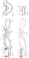
- Fig. 1 an inventive water drain is shown as an embodiment in longitudinal section.
- the main flow direction of the water runs from left to right and corresponds to the representation of the nominal installation position, wherein a provided with the reference numeral 1 nominal water level is located.
- a pipe socket 2 can be seen, for example, can be connected to the underside of a conventional shower drainage channel and waste water from the bottom drain formed by the gutter down flow when the shower is used.
- the pipe socket 2 is inserted into a flared end of a drain-pot-like cylindrical part 3 of the water outlet and sealed and held by a seal 4 and a clamp-like locking ring 5.
- the structures described so far are rotationally symmetric and known per se.
- the cylindrical part 3 of the drain pot continues downwards in a no longer rotationally symmetrical section 6 of the drain pot, which has an inclined surface 6 to the left and a knee-like transition 7 to the right, wherein the inclined surface 6 approximately from the central axis of the cylindrical part 3 of the drain pot continues horizontally and the non-rotationally symmetrical parts of the drain pot with respect to the diameter of the cylindrical part 3 in the direction perpendicular to the plane slightly taper, as in Fig. 3 indicated.
- the knee 7 forms a bottleneck and connects the drain pot 3, 6 with an outer part 8 of a first siphon stage of the water drain.
- This outer part has a to the right initially only slightly and without edges rising bottom, in contrast to the upper wall right of the knee 7 increases significantly and thus in the outer part 8, a relatively large volume of water, in this case 210 cm 3 , can be maintained, which corresponds to about twice the volume of water in the drain pot.
- first maximum point 9 in height
- second maximum point 11 determines the nominal water level 1 and thus also the sealing water level of the first siphon stage opposite the knee 7 (ie the lowest point of the upper wall of the water outlet there).
- a second knee 10 is drawn much less deeply down than the knee 7 of the first siphon stage.
- the upper wall is drawn less deep down in the region of the present here second siphon as in the area of the first knee 7. Accordingly, the second siphon between the two maximum points 9 and 11 has a much smaller sealing water level.
- the upper wall maintains apart between the two maximum points 9 and 11 by their distance from the bottom wall of the air duct still to be discussed below a substantially constant flow cross section within the second siphon, which is also significantly smaller than the upstream flow cross sections, only the first knee 7 has an approximately comparable flow cross-section. It should be added that the water drain between the non-cylindrical part 6 of the drain pot and the second maximum point 11 has substantially the same width in the direction perpendicular to the plane of the drawing.
- the typical for the invention air duct namely in the form of an approximately triangular and downwardly open extension 13 of the actually substantially rectangular (with rounded corners) water channel of the process below.
- the air duct is a topmost small area 14 which increases in size Fig. 2
- the extension 13 is filled with water at a nominal water level.
- the nominal water level 1 remains slight, in this case only about 0.2 mm, below the inner upper edge of the extension 13, so that the second siphon stage is shorted to a quantitatively small extent at nominal water level and without external pressure difference.
- the function of the air channel 14 is to restore the internal air cushion between the two siphon stages, ie above the water level 1 of the storage part 8, above the first maximum point 9 and above the water level 1 on the inside of the second siphon stage, if there is a full filling in a drain operation has, because this air cushion has been rinsed out over time.
- This restoration of the internal air cushion significantly reduces in the experience of the inventors, the risk that the entire water flow unintentionally completely or largely idle and its function is lost or impaired in its function.
- an air duct could in principle also be provided in non-integrated form and / or as a pipe section separated from the water channel and / or in the first siphon stage, in the latter case because of the necessity of the seal 4 and the securing ring 5, these higher would have to be laid, which would worsen the overall height.
- the water drain strictly speaking without the pipe socket 2, but in many cases more parts, for example, the floor drain are provided on the locking ring 5, to take into account.
- double siphon shown here could also have more than two siphon stages with a similar logic of the invention, in which case the air channel would short-circuit an outer siphon stage, possibly both. In many cases, however, the distribution of a desired total sealing water level is sufficient, as here, two siphon stages.
- the entire water drain can be designed as a one-piece Kunststoffblasteil, in the present case including the extension 13 and thus the air duct 14th
- the lower main section which is filled with water in the nominal water level, flows through the extension 13 at each drainage process and hardly impurities settle there due to lack of ground and the drainage floor between the cylindrical part 3 of the drain pot and the first maximum point 9 is very smooth and flat and despite the considerable storage volume in the storage part 8 does not provide any contamination-critical points, in particular is flushed well.
Claims (14)
- Dispositif d'évacuation d'eau, comportant:un bac d'évacuation côté entrée (3, 6),une conduite d'évacuation (12) raccordée à ce dernier, etun système de blocage d'odeur à siphons multiples (3, 6-11) comportant une pluralité de structures de siphon montées consécutivement en série présentant une zone d'air intérieure et une zone d'air marginale,caractérisé en ce qu'il est prévu un canal d'air (13, 14) entre la zone d'air intérieure et la zone d'air marginale, dans le dispositif d'évacuation d'eau, au niveau d'un côté admission et/ou évacuation du dispositif d'évacuation, lequel relie la zone d'air intérieure à la zone d'air marginale,les termes de zone d'air intérieure, zone d'air marginale et canal d'air se rapportant à un état de repos du dispositif d'évacuation sans différence de pression extérieure le long du dispositif d'évacuation et avec remplissage total des diverses structures de siphon.
- Dispositif d'évacuation d'eau selon la revendication 1, dans lequel le système de blocage d'odeur à siphons multiples (3, 6-11) est un système de blocage d'odeur à double siphon.
- Dispositif d'évacuation d'eau selon la revendication 1 ou 2, dans lequel les niveaux d'eau (1) nominaux des diverses structures de siphon (3-8, 9-11) du système de blocage d'odeur (3, 6-11) sont juxtaposés, en présentant donc un chevauchement selon une projection horizontale.
- Dispositif d'évacuation d'eau selon l'une quelconque des revendications précédentes, dans lequel le canal d'air (13, 14) est prévu entre la zone d'air marginale du côté évacuation et la zone d'air intérieure.
- Dispositif d'évacuation d'eau selon l'une quelconque des revendications précédentes, dans lequel le système de blocage d'odeur à siphons multiples (3, 6-11) est constitué d'un seul tenant eu égard aux parois extérieures de la partie servant à conduire l'eau, en s'agissant de préférence d'une pièce en plastique soufflée.
- Dispositif d'évacuation d'eau selon la revendication 5, dans lequel le siphon côté admission (3-8) du système de blocage d'odeur à siphons multiples (3, 6-11) est défini par ladite pièce.
- Dispositif d'évacuation d'eau selon la revendication 5 ou 6, dans lequel le canal d'air est intégré dans ladite pièce.
- Dispositif d'évacuation d'eau selon l'une quelconque des revendications précédentes, dans lequel le canal d'air (13, 14) est ouvert vers le bas, vers le niveau d'eau nominal (1) du système de blocage d'odeur à siphons multiples (3, 6-11).
- Dispositif d'évacuation d'eau selon la revendication 8, dans lequel le canal d'air (13, 14) va en s'élargissant vers le bas, vers le niveau d'eau nominal (1) du système de blocage d'odeur à siphons multiples (3, 6-11).
- Dispositif d'évacuation d'eau selon l'une quelconque des revendications précédentes, dans lequel le volume d'eau nominal du siphon côté entrée (6-8), en dehors (8) du bac d'évacuation côté entrée (3, 6) est d'au moins 1,4 fois celui présent à l'intérieur du bac d'évacuation côté entrée (3, 6).
- Dispositif d'évacuation d'eau selon l'une quelconque des revendications précédentes, dans lequel la section transversale du point le plus étroit (7) entre le bac d'évacuation (3, 6) et la partie du siphon côté entrée qui est située à l'extérieur du bac d'évacuation correspond au maximum à 70 % de la section transversale maximale située à l'intérieur du bac d'évacuation (3, 6), mesurée perpendiculairement au sens d'écoulement principal.
- Dispositif d'évacuation d'eau selon l'une quelconque des revendications précédentes, présentant une hauteur d'installation totale maximale de 7,5 cm.
- Utilisation d'un système d'évacuation d'eau selon l'une quelconque des revendications précédentes en tant qu'évacuation de sanitaire au sol.
- Utilisation selon la revendication 13, dans laquelle l'évacuation de sanitaire au sol est une évacuation de receveur de douche.
Priority Applications (2)
| Application Number | Priority Date | Filing Date | Title |
|---|---|---|---|
| EP14003132.9A EP2995731B1 (fr) | 2014-09-10 | 2014-09-10 | Dispositif d'écoulement d'eau doté d'un système de blocage d'odeur à siphons multiples |
| PL14003132T PL2995731T3 (pl) | 2014-09-10 | 2014-09-10 | Odpływ wody z wielosyfonowym zamknięciem antyzapachowym |
Applications Claiming Priority (1)
| Application Number | Priority Date | Filing Date | Title |
|---|---|---|---|
| EP14003132.9A EP2995731B1 (fr) | 2014-09-10 | 2014-09-10 | Dispositif d'écoulement d'eau doté d'un système de blocage d'odeur à siphons multiples |
Publications (2)
| Publication Number | Publication Date |
|---|---|
| EP2995731A1 EP2995731A1 (fr) | 2016-03-16 |
| EP2995731B1 true EP2995731B1 (fr) | 2017-01-11 |
Family
ID=51542127
Family Applications (1)
| Application Number | Title | Priority Date | Filing Date |
|---|---|---|---|
| EP14003132.9A Active EP2995731B1 (fr) | 2014-09-10 | 2014-09-10 | Dispositif d'écoulement d'eau doté d'un système de blocage d'odeur à siphons multiples |
Country Status (2)
| Country | Link |
|---|---|
| EP (1) | EP2995731B1 (fr) |
| PL (1) | PL2995731T3 (fr) |
Families Citing this family (2)
| Publication number | Priority date | Publication date | Assignee | Title |
|---|---|---|---|---|
| CN107514034A (zh) * | 2017-08-24 | 2017-12-26 | 俞如 | 一种排水管下游设置存水弯的排除废水系统 |
| CN109138128B (zh) * | 2018-09-29 | 2024-05-03 | 日丰企业(佛山)有限公司 | 地漏排水结构 |
Citations (3)
| Publication number | Priority date | Publication date | Assignee | Title |
|---|---|---|---|---|
| US180859A (en) * | 1876-08-08 | Improvement in sewer-gas traps | ||
| US260563A (en) * | 1882-07-04 | Sewer-trap | ||
| DE20017967U1 (de) * | 2000-10-20 | 2001-01-25 | Torras Pique Jorge | Kombisiphon |
Family Cites Families (1)
| Publication number | Priority date | Publication date | Assignee | Title |
|---|---|---|---|---|
| IT1394289B1 (it) * | 2009-03-05 | 2012-06-06 | Valsir Spa | Dispositivo di scarico d'acqua con sifone, in particolare per docce a pavimento e piatti doccia |
-
2014
- 2014-09-10 PL PL14003132T patent/PL2995731T3/pl unknown
- 2014-09-10 EP EP14003132.9A patent/EP2995731B1/fr active Active
Patent Citations (3)
| Publication number | Priority date | Publication date | Assignee | Title |
|---|---|---|---|---|
| US180859A (en) * | 1876-08-08 | Improvement in sewer-gas traps | ||
| US260563A (en) * | 1882-07-04 | Sewer-trap | ||
| DE20017967U1 (de) * | 2000-10-20 | 2001-01-25 | Torras Pique Jorge | Kombisiphon |
Also Published As
| Publication number | Publication date |
|---|---|
| PL2995731T3 (pl) | 2017-07-31 |
| EP2995731A1 (fr) | 2016-03-16 |
Similar Documents
| Publication | Publication Date | Title |
|---|---|---|
| DE202014007392U1 (de) | Wasserablauf mit Mehrfachsiphon-Geruchsverschluss | |
| EP3309310B1 (fr) | Trop-plein d'eaux pluviales destiné à les collecter et stocker | |
| DE102015119821A1 (de) | Versickerungsrinnenelement | |
| EP2581508B1 (fr) | Installation de relèvement des eaux usées | |
| EP2508686B1 (fr) | Installation de retenue pour l'eau de précipitation et les eaux usées | |
| DE102005012439A1 (de) | Wasserabführvorrichtung | |
| EP2995731B1 (fr) | Dispositif d'écoulement d'eau doté d'un système de blocage d'odeur à siphons multiples | |
| DE202008012099U1 (de) | Verbesserter Schmutzwassereinlauf | |
| DE10201347B4 (de) | Einlaufvorrichtung für die Abführung von Regenwasser von einem Dach | |
| EP1484453B1 (fr) | Dispositif de vidange et de trop-plein pour appareils sanitaires | |
| EP2977516A1 (fr) | Élément de rainure de substrat de filtration | |
| EP2871296B1 (fr) | Élément de rainure de substrat de filtration et système de rainure de substrat de filtration | |
| EP3199715B1 (fr) | Trop-plein pour un bac, en particulier évier | |
| EP1548193B1 (fr) | Dispositif pour empêcher l'eau d'entrer dans un puit de regard | |
| DE69728562T2 (de) | Dränagerinne | |
| DE19916964C2 (de) | Rückhalteanlage für Niederschlagswasser und Abwasser | |
| EP2636812A1 (fr) | Procédé et dispositif de drainage des eaux pluviales de toit sous la forme d'un drainage principal et d'un drainage de secours | |
| DE102007042527A1 (de) | Notablauf zur Entwässerung einer Fläche | |
| DE102016110694A1 (de) | Ablaufventil | |
| DE202007011126U1 (de) | Sedimentationsanlage | |
| EP3421676B1 (fr) | Élément de siphon à installer dans un écoulement, en particulier dans un écoulement d'un urinoir sans eau | |
| EP2405063B1 (fr) | Agencement de traitement d'eaux usées | |
| DE102013102379A1 (de) | Ablaufanordnung | |
| DE202014011094U1 (de) | Filtersubstratrinnenelement | |
| AT523236B1 (de) | Ablaufvorrichtung |
Legal Events
| Date | Code | Title | Description |
|---|---|---|---|
| PUAI | Public reference made under article 153(3) epc to a published international application that has entered the european phase |
Free format text: ORIGINAL CODE: 0009012 |
|
| 17P | Request for examination filed |
Effective date: 20150311 |
|
| AK | Designated contracting states |
Kind code of ref document: A1 Designated state(s): AL AT BE BG CH CY CZ DE DK EE ES FI FR GB GR HR HU IE IS IT LI LT LU LV MC MK MT NL NO PL PT RO RS SE SI SK SM TR |
|
| AX | Request for extension of the european patent |
Extension state: BA ME |
|
| RBV | Designated contracting states (corrected) |
Designated state(s): AL AT BE BG CH CY CZ DE DK EE ES FI FR GB GR HR HU IE IS IT LI LT LU LV MC MK MT NL NO PL PT RO RS SE SI SK SM TR |
|
| GRAP | Despatch of communication of intention to grant a patent |
Free format text: ORIGINAL CODE: EPIDOSNIGR1 |
|
| INTG | Intention to grant announced |
Effective date: 20160715 |
|
| GRAS | Grant fee paid |
Free format text: ORIGINAL CODE: EPIDOSNIGR3 |
|
| STAA | Information on the status of an ep patent application or granted ep patent |
Free format text: STATUS: GRANT OF PATENT IS INTENDED |
|
| GRAA | (expected) grant |
Free format text: ORIGINAL CODE: 0009210 |
|
| STAA | Information on the status of an ep patent application or granted ep patent |
Free format text: STATUS: THE PATENT HAS BEEN GRANTED |
|
| AK | Designated contracting states |
Kind code of ref document: B1 Designated state(s): AL AT BE BG CH CY CZ DE DK EE ES FI FR GB GR HR HU IE IS IT LI LT LU LV MC MK MT NL NO PL PT RO RS SE SI SK SM TR |
|
| REG | Reference to a national code |
Ref country code: GB Ref legal event code: FG4D Free format text: NOT ENGLISH |
|
| REG | Reference to a national code |
Ref country code: CH Ref legal event code: EP |
|
| REG | Reference to a national code |
Ref country code: AT Ref legal event code: REF Ref document number: 861429 Country of ref document: AT Kind code of ref document: T Effective date: 20170115 |
|
| REG | Reference to a national code |
Ref country code: IE Ref legal event code: FG4D Free format text: LANGUAGE OF EP DOCUMENT: GERMAN |
|
| REG | Reference to a national code |
Ref country code: CH Ref legal event code: NV Representative=s name: E. BLUM AND CO. AG PATENT- UND MARKENANWAELTE , CH |
|
| REG | Reference to a national code |
Ref country code: DE Ref legal event code: R096 Ref document number: 502014002429 Country of ref document: DE |
|
| REG | Reference to a national code |
Ref country code: SE Ref legal event code: TRGR |
|
| REG | Reference to a national code |
Ref country code: NL Ref legal event code: FP |
|
| REG | Reference to a national code |
Ref country code: LT Ref legal event code: MG4D |
|
| PG25 | Lapsed in a contracting state [announced via postgrant information from national office to epo] |
Ref country code: LT Free format text: LAPSE BECAUSE OF FAILURE TO SUBMIT A TRANSLATION OF THE DESCRIPTION OR TO PAY THE FEE WITHIN THE PRESCRIBED TIME-LIMIT Effective date: 20170111 Ref country code: FI Free format text: LAPSE BECAUSE OF FAILURE TO SUBMIT A TRANSLATION OF THE DESCRIPTION OR TO PAY THE FEE WITHIN THE PRESCRIBED TIME-LIMIT Effective date: 20170111 Ref country code: IS Free format text: LAPSE BECAUSE OF FAILURE TO SUBMIT A TRANSLATION OF THE DESCRIPTION OR TO PAY THE FEE WITHIN THE PRESCRIBED TIME-LIMIT Effective date: 20170511 Ref country code: GR Free format text: LAPSE BECAUSE OF FAILURE TO SUBMIT A TRANSLATION OF THE DESCRIPTION OR TO PAY THE FEE WITHIN THE PRESCRIBED TIME-LIMIT Effective date: 20170412 Ref country code: HR Free format text: LAPSE BECAUSE OF FAILURE TO SUBMIT A TRANSLATION OF THE DESCRIPTION OR TO PAY THE FEE WITHIN THE PRESCRIBED TIME-LIMIT Effective date: 20170111 Ref country code: NO Free format text: LAPSE BECAUSE OF FAILURE TO SUBMIT A TRANSLATION OF THE DESCRIPTION OR TO PAY THE FEE WITHIN THE PRESCRIBED TIME-LIMIT Effective date: 20170411 |
|
| PG25 | Lapsed in a contracting state [announced via postgrant information from national office to epo] |
Ref country code: BG Free format text: LAPSE BECAUSE OF FAILURE TO SUBMIT A TRANSLATION OF THE DESCRIPTION OR TO PAY THE FEE WITHIN THE PRESCRIBED TIME-LIMIT Effective date: 20170411 Ref country code: ES Free format text: LAPSE BECAUSE OF FAILURE TO SUBMIT A TRANSLATION OF THE DESCRIPTION OR TO PAY THE FEE WITHIN THE PRESCRIBED TIME-LIMIT Effective date: 20170111 Ref country code: PT Free format text: LAPSE BECAUSE OF FAILURE TO SUBMIT A TRANSLATION OF THE DESCRIPTION OR TO PAY THE FEE WITHIN THE PRESCRIBED TIME-LIMIT Effective date: 20170511 Ref country code: LV Free format text: LAPSE BECAUSE OF FAILURE TO SUBMIT A TRANSLATION OF THE DESCRIPTION OR TO PAY THE FEE WITHIN THE PRESCRIBED TIME-LIMIT Effective date: 20170111 Ref country code: RS Free format text: LAPSE BECAUSE OF FAILURE TO SUBMIT A TRANSLATION OF THE DESCRIPTION OR TO PAY THE FEE WITHIN THE PRESCRIBED TIME-LIMIT Effective date: 20170111 |
|
| REG | Reference to a national code |
Ref country code: FR Ref legal event code: PLFP Year of fee payment: 4 |
|
| REG | Reference to a national code |
Ref country code: DE Ref legal event code: R097 Ref document number: 502014002429 Country of ref document: DE |
|
| PG25 | Lapsed in a contracting state [announced via postgrant information from national office to epo] |
Ref country code: EE Free format text: LAPSE BECAUSE OF FAILURE TO SUBMIT A TRANSLATION OF THE DESCRIPTION OR TO PAY THE FEE WITHIN THE PRESCRIBED TIME-LIMIT Effective date: 20170111 Ref country code: RO Free format text: LAPSE BECAUSE OF FAILURE TO SUBMIT A TRANSLATION OF THE DESCRIPTION OR TO PAY THE FEE WITHIN THE PRESCRIBED TIME-LIMIT Effective date: 20170111 Ref country code: SK Free format text: LAPSE BECAUSE OF FAILURE TO SUBMIT A TRANSLATION OF THE DESCRIPTION OR TO PAY THE FEE WITHIN THE PRESCRIBED TIME-LIMIT Effective date: 20170111 |
|
| PLBE | No opposition filed within time limit |
Free format text: ORIGINAL CODE: 0009261 |
|
| STAA | Information on the status of an ep patent application or granted ep patent |
Free format text: STATUS: NO OPPOSITION FILED WITHIN TIME LIMIT |
|
| PG25 | Lapsed in a contracting state [announced via postgrant information from national office to epo] |
Ref country code: SM Free format text: LAPSE BECAUSE OF FAILURE TO SUBMIT A TRANSLATION OF THE DESCRIPTION OR TO PAY THE FEE WITHIN THE PRESCRIBED TIME-LIMIT Effective date: 20170111 Ref country code: DK Free format text: LAPSE BECAUSE OF FAILURE TO SUBMIT A TRANSLATION OF THE DESCRIPTION OR TO PAY THE FEE WITHIN THE PRESCRIBED TIME-LIMIT Effective date: 20170111 |
|
| 26N | No opposition filed |
Effective date: 20171012 |
|
| PG25 | Lapsed in a contracting state [announced via postgrant information from national office to epo] |
Ref country code: SI Free format text: LAPSE BECAUSE OF FAILURE TO SUBMIT A TRANSLATION OF THE DESCRIPTION OR TO PAY THE FEE WITHIN THE PRESCRIBED TIME-LIMIT Effective date: 20170111 |
|
| PG25 | Lapsed in a contracting state [announced via postgrant information from national office to epo] |
Ref country code: MC Free format text: LAPSE BECAUSE OF FAILURE TO SUBMIT A TRANSLATION OF THE DESCRIPTION OR TO PAY THE FEE WITHIN THE PRESCRIBED TIME-LIMIT Effective date: 20170111 |
|
| REG | Reference to a national code |
Ref country code: IE Ref legal event code: MM4A |
|
| PG25 | Lapsed in a contracting state [announced via postgrant information from national office to epo] |
Ref country code: LU Free format text: LAPSE BECAUSE OF NON-PAYMENT OF DUE FEES Effective date: 20170910 |
|
| PG25 | Lapsed in a contracting state [announced via postgrant information from national office to epo] |
Ref country code: IE Free format text: LAPSE BECAUSE OF NON-PAYMENT OF DUE FEES Effective date: 20170910 |
|
| REG | Reference to a national code |
Ref country code: FR Ref legal event code: PLFP Year of fee payment: 5 |
|
| PG25 | Lapsed in a contracting state [announced via postgrant information from national office to epo] |
Ref country code: MT Free format text: LAPSE BECAUSE OF FAILURE TO SUBMIT A TRANSLATION OF THE DESCRIPTION OR TO PAY THE FEE WITHIN THE PRESCRIBED TIME-LIMIT Effective date: 20170111 |
|
| GBPC | Gb: european patent ceased through non-payment of renewal fee |
Effective date: 20180910 |
|
| PG25 | Lapsed in a contracting state [announced via postgrant information from national office to epo] |
Ref country code: HU Free format text: LAPSE BECAUSE OF FAILURE TO SUBMIT A TRANSLATION OF THE DESCRIPTION OR TO PAY THE FEE WITHIN THE PRESCRIBED TIME-LIMIT; INVALID AB INITIO Effective date: 20140910 |
|
| PG25 | Lapsed in a contracting state [announced via postgrant information from national office to epo] |
Ref country code: CY Free format text: LAPSE BECAUSE OF FAILURE TO SUBMIT A TRANSLATION OF THE DESCRIPTION OR TO PAY THE FEE WITHIN THE PRESCRIBED TIME-LIMIT Effective date: 20170111 Ref country code: GB Free format text: LAPSE BECAUSE OF NON-PAYMENT OF DUE FEES Effective date: 20180910 |
|
| PG25 | Lapsed in a contracting state [announced via postgrant information from national office to epo] |
Ref country code: MK Free format text: LAPSE BECAUSE OF FAILURE TO SUBMIT A TRANSLATION OF THE DESCRIPTION OR TO PAY THE FEE WITHIN THE PRESCRIBED TIME-LIMIT Effective date: 20170111 |
|
| PG25 | Lapsed in a contracting state [announced via postgrant information from national office to epo] |
Ref country code: TR Free format text: LAPSE BECAUSE OF FAILURE TO SUBMIT A TRANSLATION OF THE DESCRIPTION OR TO PAY THE FEE WITHIN THE PRESCRIBED TIME-LIMIT Effective date: 20170111 |
|
| PG25 | Lapsed in a contracting state [announced via postgrant information from national office to epo] |
Ref country code: AL Free format text: LAPSE BECAUSE OF FAILURE TO SUBMIT A TRANSLATION OF THE DESCRIPTION OR TO PAY THE FEE WITHIN THE PRESCRIBED TIME-LIMIT Effective date: 20170111 |
|
| P01 | Opt-out of the competence of the unified patent court (upc) registered |
Effective date: 20230507 |
|
| PGFP | Annual fee paid to national office [announced via postgrant information from national office to epo] |
Ref country code: NL Payment date: 20230921 Year of fee payment: 10 Ref country code: CZ Payment date: 20230828 Year of fee payment: 10 Ref country code: AT Payment date: 20230921 Year of fee payment: 10 |
|
| PGFP | Annual fee paid to national office [announced via postgrant information from national office to epo] |
Ref country code: SE Payment date: 20230921 Year of fee payment: 10 Ref country code: PL Payment date: 20230825 Year of fee payment: 10 Ref country code: FR Payment date: 20230920 Year of fee payment: 10 Ref country code: DE Payment date: 20230919 Year of fee payment: 10 Ref country code: BE Payment date: 20230921 Year of fee payment: 10 |
|
| PGFP | Annual fee paid to national office [announced via postgrant information from national office to epo] |
Ref country code: IT Payment date: 20230922 Year of fee payment: 10 Ref country code: CH Payment date: 20231001 Year of fee payment: 10 |