EP3199715A2 - Overflow for a basin, in particular rinsing basin - Google Patents
Overflow for a basin, in particular rinsing basin Download PDFInfo
- Publication number
- EP3199715A2 EP3199715A2 EP16197956.2A EP16197956A EP3199715A2 EP 3199715 A2 EP3199715 A2 EP 3199715A2 EP 16197956 A EP16197956 A EP 16197956A EP 3199715 A2 EP3199715 A2 EP 3199715A2
- Authority
- EP
- European Patent Office
- Prior art keywords
- overflow
- sink
- flow channel
- section
- opening
- Prior art date
- Legal status (The legal status is an assumption and is not a legal conclusion. Google has not performed a legal analysis and makes no representation as to the accuracy of the status listed.)
- Granted
Links
Images
Classifications
-
- E—FIXED CONSTRUCTIONS
- E03—WATER SUPPLY; SEWERAGE
- E03C—DOMESTIC PLUMBING INSTALLATIONS FOR FRESH WATER OR WASTE WATER; SINKS
- E03C1/00—Domestic plumbing installations for fresh water or waste water; Sinks
- E03C1/12—Plumbing installations for waste water; Basins or fountains connected thereto; Sinks
- E03C1/22—Outlet devices mounted in basins, baths, or sinks
- E03C1/23—Outlet devices mounted in basins, baths, or sinks with mechanical closure mechanisms
- E03C1/232—Outlet devices mounted in basins, baths, or sinks with mechanical closure mechanisms combined with overflow devices
-
- E—FIXED CONSTRUCTIONS
- E03—WATER SUPPLY; SEWERAGE
- E03C—DOMESTIC PLUMBING INSTALLATIONS FOR FRESH WATER OR WASTE WATER; SINKS
- E03C1/00—Domestic plumbing installations for fresh water or waste water; Sinks
- E03C1/12—Plumbing installations for waste water; Basins or fountains connected thereto; Sinks
- E03C1/24—Overflow devices for basins or baths
-
- E—FIXED CONSTRUCTIONS
- E03—WATER SUPPLY; SEWERAGE
- E03C—DOMESTIC PLUMBING INSTALLATIONS FOR FRESH WATER OR WASTE WATER; SINKS
- E03C1/00—Domestic plumbing installations for fresh water or waste water; Sinks
- E03C1/12—Plumbing installations for waste water; Basins or fountains connected thereto; Sinks
- E03C1/18—Sinks, whether or not connected to the waste-pipe
-
- E—FIXED CONSTRUCTIONS
- E03—WATER SUPPLY; SEWERAGE
- E03C—DOMESTIC PLUMBING INSTALLATIONS FOR FRESH WATER OR WASTE WATER; SINKS
- E03C1/00—Domestic plumbing installations for fresh water or waste water; Sinks
- E03C1/12—Plumbing installations for waste water; Basins or fountains connected thereto; Sinks
- E03C1/24—Overflow devices for basins or baths
- E03C1/244—Separate devices to be placed on the outlet opening
Definitions
- the invention relates to an overflow for a sink according to the preamble of claim 1, with at least one inlet opening, which is intended for mounting on a sink of the sink or on an overflow well or a separate spout, and with an outlet opening for mounting on a Drain or vent valve of the basin or the sink is determined, wherein between the inlet opening and outlet opening a flow channel for a fluid or water is arranged.
- the invention also relates to a sink with at least one overflow, which sink comprises an opening in a side wall of a sink or an opening in a horizontal surface of the sink, preferably in the region of an overflow well or a separate spout, which opening fluidly with an overflow Drain of the sink is connected, according to the preamble of claim 13.
- the invention relates to a retrofit element for such a sink with overflow, which retrofit element is adapted to be fitted into the existing overflow of the sink.
- Rinsing known type especially kitchen sinks, regularly have an overflow, as defined above, so that at a closure of the actual rinse cycle excess water from the sink or an overflow tray can run when the water level has reached a certain level or if water in the overflow trough or reaches the spout, eg from a drainer of the sink. This should avoid flooding and corresponding damage.
- the invention has for its object to provide an improved overflow in a simple and cost-effective manner, so that from the basin and / or the overflow trough or the separate spout overflowing water can be optimally and safely dissipated.
- this solution should be retrofitted even with existing sinks without major construction effort (retrofitted).
- an overflow for a sink preferably a kitchen sink with at least one sink and an overflow well or a separate spout, with at least one inlet opening, which is intended for mounting on the basin or on the overflow well or the separate spout, and with an outlet opening , which is intended for mounting on a drain or vent valve of the sink or the basin, wherein between the inlet opening and outlet opening a flow channel for a fluid is arranged, characterized in that in the flow channel at least a portion (flow channel section) is provided in the flow channel has a substantially circular cross-section.
- the overflow may in particular also have two or more inlet openings, one of which is present on the basin and another on the overflow recess or the separate spout or a further basin if so mounted or mountable.
- the realization of several separate inventive overflows is possible, for example, for each sink or sink sink and overflow trough or spout.
- a sink according to the invention with at least one overflow which sink comprises an opening in a side wall of a sink or an opening in a horizontal surface of the sink, preferably in the region of an overflow well or a separate spout, which opening via a Overflow fluidly connected to a drain of the sink, characterized in that the sink has an overflow according to the invention or a further development thereof.
- the invention provides a retrofit element for a sink with overflow, which sink comprises an opening in a side wall of a sink or an opening in a horizontal surface of the sink, preferably in the region of an overflow trough or a separate spout, which opening fluidly with the overflow an outlet of the sink is connected, which retrofit element is adapted to be fitted into the overflow, wherein an outer contour of the retrofit element substantially corresponds to an inner contour of the overflow in a region, and wherein the retrofit element has at least one opening, the inner contour of a substantially has circular cross-section.
- At least one section is provided in the flow channel defined between the at least one inlet opening and the outlet opening of the overflow, in which the flow channel has a substantially circular cross section, even if the flow channel itself - which is the rule - a thereof has a different cross-sectional geometry.
- Said flow channel section of circular cross-section as fluid drains through the weir, provides vortex formation similar to that of an upturned bottle when set in motion about its longitudinal axis.
- This has a particularly beneficial effect, especially with overflow wells and separate spouts, because a back pressure can not really build up in this arrangement.
- the flow channel has a constant cross section in the section, which can have a positive effect on the vortex formation. This can apply to at least a major part of the mentioned section.
- the flow channel has at least one, for example conical, taper in its cross section in the section, viewed in the flow direction of the fluid. This may for example be the case in the region of the inlet opening.
- the flow channel in the section can also have an extension of its cross section, preferably in the region or in the direction of the outlet opening.
- the section has a certain length L, which may be numerically linked to a diameter D of the section.
- L f ⁇ D.
- another embodiment of the overflow according to the invention provides that a sum of the cross sections of the sections, if several such sections are present, or the cross sections of the one existing section in the range of about 175 mm 2 , most preferably between about 150 mm 2 and about 200 mm 2 .
- the overflow provides that the (several) sections are arranged next to one another, on a line, in the manner of a triangle, offset in zigzag or in another relative position to one another , preferably in each case based on the location of their centers.
- the at least one section or at least one of the plurality of sections may be arranged in the region of the inlet opening of the overflow, for example in the region of a so-called overflow head.
- the overflow head is that part of the overflow which is physically mounted directly in the region of an overflow opening of the sink or of the sink at this or on this. The same applies to the inlet opening in the region of an overflow trough or a separate spout.
- the at least one section or one of the several sections is arranged in the region of the outlet opening of the overflow, that is to say rather in the direction of the rinsing outlet.
- the circular flow channel section can also be arranged at any other point of the overflow or the overflow flow channel.
- the at least one section or at least one of the plurality of sections is arranged in the region of an elbow of the flow channel, which angle piece a first, when mounted vertical portion of the flow channel in a second, horizontal in assembly section the flow channel transferred.
- the at least one flow channel section may be arranged in the region of the first section (ie vertically) and / or in the region of the second section (ie horizontally).
- the retrofit element is designed to be fitted into an existing overflow.
- an outer contour of the retrofit element substantially correspond to an inner contour of the overflow in a region.
- the retrofit element can be used inside, as a kind of use, in an existing overflow. This can basically be done at any point of the overflow, so for example in the overflow head.
- the above mentioned can be Overflow head, if this includes the said circular flow channel section, even consider themselves as a retrofit element, because he can replace an existing overflow head of an existing overflow.
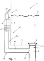
- FIG. 1 is a schematic and partially in section a sink, in particular a kitchen sink, shown, which is generally designated by the reference numeral 1.
- the sink 1 comprises at least one sink 2, of which only a lower corner area is shown, which comprises a pool wall 3 and a pool floor 4.
- a drain opening is provided at the reference numeral 5, which fluidly communicates with a sink drain 6, which is known per se.
- a sealing plug or valve plug 7 is arranged, which closes the drain opening 5 in a fluid-tight manner in the exemplary embodiment shown, so that no water can flow out of the sink basin 2 through the drain opening 5.
- flushing water 2 is contained in the sink tank 2 up to a water level 9 shown schematically.
- the water level 9 is at the height of an opening 10 in the pool wall 3, which opening 10 can also be referred to as an overflow opening. Due to the selected representation, the opening 10 in Figure 1 is not visible.
- the so-called overflow head 11 of a known overflow 12 is mounted on the outside of the pool wall 3, via which overflow 12 water 8 can flow from the sink 2 to the sink drain 6, when the water level 9 within the sink 2 a certain level reaches or exceeds.
- the overflow 12 comprises, in addition to the already mentioned overflow head 11, an inlet opening 13 in the region of the overflow head 11, which inlet opening 13 communicates with the aforementioned opening 10 in the basin wall 3 of the sink 2.
- Around the inlet opening 13 around a seal is regularly arranged to seal the overflow head 11 fluid-tight against the pool wall 3. This seal is in FIG. 1 not visible.
- At the overflow head 11 closes according to FIG.
- overflow pipe 14 which defines an outlet opening 15 at its end facing away from the overflow head 11, via which the overflow 12 opens into the flushing outlet 6.
- Inlet opening 13, overflow head 11, overflow pipe 14 and outlet opening 15 define in this way a flow channel 14a from the opening 10 in the pool wall 3 of the sink 2 to the sink 6, so that water 8 can flow from the sink 2 through the overflow 12 when the water level 9 - as already stated was - reaches or exceeds a certain level (a certain level).
- FIG. 1 The so far by means of FIG. 1 described embodiment is known per se and comes in commercial (kitchen) sinks, such as the sink 1 shown, used regularly.
- the present invention now relates to improvements in the area of the overflow 12, in particular of the overflow head 11, which will be discussed in more detail with reference to the following figures.
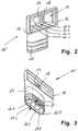
- FIG. 2 shows in perspective overall view of an overflow head 11 of an overflow according to the invention, the in FIG. 2 not shown.
- the overflow head 11 ' also includes the already mentioned, approximately rectangular inlet opening 13, which is surrounded by a correspondingly shaped sealing surface 16.
- Approximately in the center of the otherwise slightly funnel-shaped inwardly tapering inlet opening 13 is centrally approximately circular-cylindrical reinforced structure 17 which has a mounting hole 18 for attachment of the overflow head 11 in the region of the pool wall 3 (see. FIG. 1 ) trains.
- In a lower boundary surface 19 of the inlet opening 13 four openings or holes 20.1 to 20.4 are present side by side in a row, which extend parallel to each other through a connecting piece 21 of the overflow head 11. These openings or holes 20.1 to 20.4 each define a flow channel section of the overflow 12 (see. FIG.
- the connecting piece 21 of the overflow head 11 has on the outside protruding formations, which can serve for the attachment of a deferred tube or hose (not shown) or for reinforcing purposes.
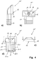
- FIG. 3 shows the overflow head 11 in a further perspective view obliquely from below, so that the formation and arrangement of the openings / holes or flow channel sections 20.1 to 20.4 can be clearly seen.
- These are - as already stated - side by side on a line (relative to their virtual centers, not shown) and each have approximately the same diameter D.
- the invention is by no means limited to the arrangement, number or size configuration of the openings / bores 20.1 to 20.4 shown here.
- the apertures / bores 20.1 - 20.4 may also have different diameters D, and there may be more or less than the four apertures / holes 20.1 - 20.4 shown.
- these may be arranged relative to each other in a different geometry, for example offset, in zigzag, in the manner of a square, triangle or the like, or, for example, only a single such breakthrough may be present. It is essential in any case that the opening or the openings have or have an approximately circular diameter, although the connecting piece 21 of the overflow head 11 or its inlet opening 13 has a deviating geometry (oval or rectangular). Applicant has found that the presence of circular flow channel sections significantly improves the overflow water flow behavior in the overflow area, comparable to the improved leakage of water from an over-the-top bottle as it rotates about the longitudinal axis of the bottle becomes.
- the openings / bores 20.1 - 20.4 can have a terminal widening in the region of the inlet opening 13 and / or in the area of a free (lower) end of the connecting piece 21, as in FIG FIG. 3 at reference 22.4 for the bore 20.4 is shown as an example.
- FIG. 4 shows further views of the overflow head 11 'according to the FIGS. 2 and 3 .
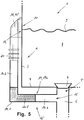
- FIG. 5 schematically shows an alternative embodiment of the overflow according to the invention (in FIG. 5 denoted by reference numeral 12 '), in which, alternatively or in addition to the flow channel sections with a circular cross section formed in the region of the overflow head 11, 11', a (further) such flow channel section is provided in the region of the overflow pipe 14.
- said further flow channel section is designated by reference numeral 20.5 and arranged in the region of an angle 14.1, which connects a first pipe part 14.2, which is connected in extension thereof to the connecting piece 21 of the overflow head 11, 11 ', with a second pipe part 14.3, which is connected to the sink outlet 6 and defines the outlet opening 15 of the overflow 12 '.
- the elbow or angle part 14.1 is in FIG. 5 hatched shown.
- the at least one flow channel section 20.5 could alternatively also be arranged in the region of the first pipe part 14.2 and / or of the second pipe part 14.3.
- the present proposed improvement in the field of (scavenging) overflow can also be realized by retrofitting an already existing overflow in an existing sink, for example by a corresponding pipe or elbow 14.1 - 14.3 installed later or a corresponding use is used in an existing overflow.
- the same also applies to the overflow head 11 ', which can replace an existing, known overflow head 11.
- said diameter D of the openings / holes in the range of 2 to 35 mm, with smaller diameters D a corresponding plurality of openings is to be provided.
- a minimum cross-section summed over all apertures or bores should be in the range of about 150 mm 2 to about 200 mm 2 , preferably about 175 mm 2 .
- the invention is not limited to the application in the area of a sink, but it can alternatively or additionally be used in the area of a so-called. Overflow well or a separate spout.
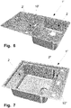
- FIG. 6 shows a flushing 1 'with overflow well 2'.
- This overflow well 2 ' has a (in the installed state) horizontally disposed opening 10', below which an inventive overflow (not shown here) is mounted or mounted to make its benefits for such flushing 1 'usable.
- FIG. 7 shows a rinse 1 "with a separate spout 2".
- This spout 2 " also has a (in the installed state) horizontally disposed opening 10", below which an inventive overflow (not shown here) is mounted or mounted to make its benefits even for such rinsing 1 "usable.
- an inventive overflow in the sinks 1 ', 1 "according to FIG. 6 or 7 additionally be provided in the area of the basin 2, as described above.
Abstract
Vorgeschlagen wird ein Überlauf für eine Spüle, mit wenigstens einer Einlauföffnung (13), die zur Montage an einem Becken oder einer Überlaufmulde oder einem separaten Ausguss der Spüle bestimmt ist, und mit einer Auslauföffnung, die zur Montage an einem Ablauf oder Lüftungsventil der Spüle bzw. des Beckens bestimmt ist, wobei zwischen Einlauföffnung (13) und Auslauföffnung ein Strömungskanal für ein Fluid angeordnet ist, dadurch gekennzeichnet, dass in dem Strömungskanal wenigstens ein Abschnitt (20.1-20.4) vorgesehen ist, in dem der Strömungskanal einen im Wesentlichen kreisrunden Querschnitt aufweist.It proposes an overflow for a sink, with at least one inlet opening (13), which is intended for installation on a basin or an overflow recess or a separate spout of the sink, and with an outlet opening for mounting on a drain or vent valve of the sink or is arranged between the inlet opening (13) and outlet opening a flow channel for a fluid, characterized in that in the flow channel at least a portion (20.1-20.4) is provided, in which the flow channel has a substantially circular cross-section ,
Description
Die Erfindung betrifft einen Überlauf für eine Spüle gemäß dem Oberbegriff des Anspruchs 1, mit wenigstens einer Einlauföffnung, die zur Montage an einem Becken der Spüle oder an einer Überlaufmulde bzw. einem separaten Ausguss bestimmt ist, und mit einer Auslauföffnung, die zur Montage an einem Ablauf oder Lüftungsventil des Beckens bzw. der Spüle bestimmt ist, wobei zwischen Einlauföffnung und Auslauföffnung ein Strömungskanal für ein Fluid bzw. Wasser angeordnet ist.The invention relates to an overflow for a sink according to the preamble of
Die Erfindung betrifft auch eine Spüle mit wenigstens einem Überlauf, welche Spüle eine Öffnung in einer Seitenwand eines Spülenbeckens oder eine Öffnung in einer horizontalen Fläche der Spüle, vorzugsweise im Bereich einer Überlaufmulde oder eines separaten Ausgusses, umfasst, welche Öffnung über einen Überlauf fluidtechnisch mit dem Ablauf der Spüle verbunden ist, gemäß dem Oberbegriff des Anspruchs 13.The invention also relates to a sink with at least one overflow, which sink comprises an opening in a side wall of a sink or an opening in a horizontal surface of the sink, preferably in the region of an overflow well or a separate spout, which opening fluidly with an overflow Drain of the sink is connected, according to the preamble of
Weiterhin betrifft die Erfindung ein Nachrüstelement für eine derartige Spüle mit Überlauf, welches Nachrüstelement dazu ausgebildet ist, in den bestehenden Überlauf der Spüle eingepasst zu werden.Furthermore, the invention relates to a retrofit element for such a sink with overflow, which retrofit element is adapted to be fitted into the existing overflow of the sink.
Spülen bekannter Art, insbesondere Küchenspülen, weisen regelmäßig einen Überlauf auf, wie oben definiert, damit bei einem Verschluss des eigentlichen Spülenablaufs überschüssiges Wasser aus dem Spülenbecken oder einer Überlaufmulde ablaufen kann, wenn der Wasserstand ein bestimmtes Niveau erreicht hat bzw. wenn Wasser in die Überlaufmulde oder den Ausguss gelangt, z.B. von einer Abtropffläche der Spüle. Dadurch sollen Überschwemmungen und entsprechende Schäden vermieden werden.Rinsing known type, especially kitchen sinks, regularly have an overflow, as defined above, so that at a closure of the actual rinse cycle excess water from the sink or an overflow tray can run when the water level has reached a certain level or if water in the overflow trough or reaches the spout, eg from a drainer of the sink. This should avoid flooding and corresponding damage.
In der Vergangenheit hat es sich zuweilen als schwierig herausgestellt, eine ordnungsgemäße Funktion des Überlaufs zu gewährleisten, der regelmäßig in der Lage sein muss, eine relativ große Wassermenge von bis zu 12 l/min aus dem Spülenbecken abzuleiten. Beispielsweise wurden zu diesem Zweck aufwändige und entsprechend kostenträchtige Entlüftungen für den Überlauf vorgesehen, damit dieser seine Sicherheitsfunktion jederzeit uneingeschränkt erfüllen kann. Insbesondere bei der Entwässerung von Überlaufmulden oder separaten Ausgüssen hat sich gezeigt, dass der für eine ordnungsgemäße Funktion erforderliche Staudruck nur schwer zu erreichen ist.In the past, it has sometimes proved difficult to ensure the proper function of the overflow, which must regularly be able to drain a relatively large amount of water of up to 12 l / min from the sink. For example, elaborate and correspondingly costly vents for the overflow have been provided for this purpose, so that this can fulfill its security function at any time without restriction. In particular, in the drainage of overflow wells or separate spouts has been shown that the necessary for proper functioning dynamic pressure is difficult to achieve.
Der Erfindung liegt die Aufgabe zugrunde, in einfacher und kostengünstiger Weise einen verbesserten Überlauf zu schaffen, damit aus dem Becken und/oder der Überlaufmulde bzw. dem separaten Ausguss überlaufendes Wasser optimal und sicher abgeleitet werden kann. Vorzugsweise soll diese Lösung auch bei bereits bestehenden Spülen ohne großen baulichen Aufwand nachträglich realisierbar (nachrüstbar) sein.The invention has for its object to provide an improved overflow in a simple and cost-effective manner, so that from the basin and / or the overflow trough or the separate spout overflowing water can be optimally and safely dissipated. Preferably, this solution should be retrofitted even with existing sinks without major construction effort (retrofitted).
Die Aufgabe wird gelöst durch einen Überlauf mit den Merkmalen des Anspruchs 1, durch eine Spüle mit den Merkmalen des Anspruchs 13 sowie durch ein Nachrüstelement mit den Merkmalen des Anspruchs 14. Vorteilhafte Weiterbildungen der jeweiligen Erfindungsgegenstände sind in den entsprechenden Unteransprüchen definiert.The object is achieved by an overflow with the features of
Erfindungsgemäß ist ein Überlauf für eine Spüle, vorzugsweise eine Küchenspüle mit wenigstens einem Spülenbecken und einer Überlaufmulde oder einem separaten Ausguss, mit wenigstens einer Einlauföffnung, die zur Montage an dem Becken oder an der Überlaufmulde bzw. dem separaten Ausguss bestimmt ist, und mit einer Auslauföffnung, die zur Montage an einem Ablauf oder Lüftungsventil der Spüle bzw. des Beckens bestimmt ist, wobei zwischen Einlauföffnung und Auslauföffnung ein Strömungskanal für ein Fluid angeordnet ist, dadurch gekennzeichnet, dass in dem Strömungskanal wenigstens ein Abschnitt (Strömungskanal-Abschnitt) vorgesehen ist, in dem der Strömungskanal einen im Wesentlichen kreisrunden Querschnitt aufweist.According to the invention, an overflow for a sink, preferably a kitchen sink with at least one sink and an overflow well or a separate spout, with at least one inlet opening, which is intended for mounting on the basin or on the overflow well or the separate spout, and with an outlet opening , which is intended for mounting on a drain or vent valve of the sink or the basin, wherein between the inlet opening and outlet opening a flow channel for a fluid is arranged, characterized in that in the flow channel at least a portion (flow channel section) is provided in the flow channel has a substantially circular cross-section.
Der Überlauf kann insbesondere auch zwei oder mehr Einlauföffnungen aufweisen, von denen eine an dem Becken und eine andere an der Überlaufmulde bzw. dem separaten Ausguss oder einem weiteren Becken -sofern vorhanden - montiert oder montierbar ist. Darüber hinaus ist auch die Realisierung mehrerer separater erfindungsgemäßer Überläufe möglich, z.B. für jedes Spülenbecken oder für Spülenbecken und Überlaufmulde bzw. Ausguss.The overflow may in particular also have two or more inlet openings, one of which is present on the basin and another on the overflow recess or the separate spout or a further basin if so mounted or mountable. In addition, the realization of several separate inventive overflows is possible, for example, for each sink or sink sink and overflow trough or spout.
Gemäß einem anderen Aspekt der Erfindung ist eine erfindungsgemäße Spüle mit wenigstens einem Überlauf, welche Spüle eine Öffnung in einer Seitenwand eines Spülenbeckens oder eine Öffnung in einer horizontalen Fläche der Spüle, vorzugsweise im Bereich einer Überlaufmulde oder eines separaten Ausgusses, umfasst, welche Öffnung über einen Überlauf fluidtechnisch mit einem Ablauf der Spüle verbunden ist, dadurch gekennzeichnet, dass die Spüle einen erfindungsgemäßen Überlauf oder eine Weiterbildung hiervon aufweist.According to another aspect of the invention, a sink according to the invention with at least one overflow, which sink comprises an opening in a side wall of a sink or an opening in a horizontal surface of the sink, preferably in the region of an overflow well or a separate spout, which opening via a Overflow fluidly connected to a drain of the sink, characterized in that the sink has an overflow according to the invention or a further development thereof.
Weiterhin schafft die Erfindung ein Nachrüstelement für eine Spüle mit Überlauf, welche Spüle eine Öffnung in einer Seitenwand eines Spülenbeckens oder eine Öffnung in einer horizontalen Fläche der Spüle, vorzugsweise im Bereich einer Überlaufmulde oder eines separaten Ausgusses, umfasst, welche Öffnung über den Überlauf fluidtechnisch mit einem Ablauf der Spüle verbunden ist, welches Nachrüstelement dazu ausgebildet ist, in den Überlauf eingepasst zu werden, wobei eine Außenkontur des Nachrüstelements im Wesentlichen einer Innenkontur des Überlaufs in einem Bereich entspricht, und wobei das Nachrüstelement wenigstens einen Durchbruch aufweist, dessen Innenkontur einen im Wesentlichen kreisrunden Querschnitt aufweist.Furthermore, the invention provides a retrofit element for a sink with overflow, which sink comprises an opening in a side wall of a sink or an opening in a horizontal surface of the sink, preferably in the region of an overflow trough or a separate spout, which opening fluidly with the overflow an outlet of the sink is connected, which retrofit element is adapted to be fitted into the overflow, wherein an outer contour of the retrofit element substantially corresponds to an inner contour of the overflow in a region, and wherein the retrofit element has at least one opening, the inner contour of a substantially has circular cross-section.
Erfindungsgemäß ist demnach vorgesehen, dass in dem zwischen der wenigstens einen Einlauföffnung und der Auslauföffnung des Überlaufs definierten Strömungskanal wenigstens ein Abschnitt vorgesehen ist, in dem der Strömungskanal einen im Wesentlichen kreisrunden Querschnitt aufweist, auch wenn der Strömungskanal an sich - was die Regel ist - eine hiervon abweichende Querschnittsgeometrie besitzt. Der genannte Strömungskanal-Abschnitt mit kreisrundem Querschnitt sorgt beim Ablaufen von Flüssigkeit durch den Überlauf für eine Wirbelbildung ähnlich wie bei einer umgedrehten Flasche, wenn diese um ihre Längsachse in Bewegung versetzt wird. Dadurch befindet sich weniger gestaute Luft im System, und das Ablaufen von Flüssigkeit durch den Überlauf wird verbessert. Dies wirkt sich vor allem bei Überlaufmulden und separaten Ausgüssen besonders vorteilhaft auf, weil sich bei dieser Anordnung ein Staudruck nicht wirklich aufbauen kann.According to the invention, it is therefore provided that at least one section is provided in the flow channel defined between the at least one inlet opening and the outlet opening of the overflow, in which the flow channel has a substantially circular cross section, even if the flow channel itself - which is the rule - a thereof has a different cross-sectional geometry. Said flow channel section of circular cross-section, as fluid drains through the weir, provides vortex formation similar to that of an upturned bottle when set in motion about its longitudinal axis. As a result, there is less jammed air in the system, and drainage of fluid through the overflow is improved. This has a particularly beneficial effect, especially with overflow wells and separate spouts, because a back pressure can not really build up in this arrangement.
In Weiterbildung des erfindungsgemäßen Überlaufs kann vorgesehen sein, dass der Strömungskanal in dem Abschnitt einen konstanten Querschnitt aufweist, was sich günstig auf die Wirbelbildung auswirken kann. Dies kann zumindest für einen größten Teil des genannten Abschnitts gelten.In a further development of the overflow according to the invention, it can be provided that the flow channel has a constant cross section in the section, which can have a positive effect on the vortex formation. This can apply to at least a major part of the mentioned section.
Alternativ oder zusätzlich kann vorgesehen sein, dass der Strömungskanal in dem Abschnitt, in Strömungsrichtung des Fluids gesehen, wenigstens eine beispielsweise konische Verjüngung seines Querschnitts aufweist. Dies kann beispielsweise im Bereich der Einlauföffnung der Fall sein. Weiterhin kann der Strömungskanal in dem Abschnitt auch eine Erweiterung seines Querschnitts aufweisen, vorzugsweise im Bereich oder in Richtung der Auslauföffnung.Alternatively or additionally, it may be provided that the flow channel has at least one, for example conical, taper in its cross section in the section, viewed in the flow direction of the fluid. This may for example be the case in the region of the inlet opening. Furthermore, the flow channel in the section can also have an extension of its cross section, preferably in the region or in the direction of the outlet opening.
Um die angesprochene Wirbelbildung weiter zu optimieren, zeichnet sich eine andere Weiterbildung des erfindungsgemäßen Überlaufs dadurch aus, dass der Abschnitt eine bestimmte Länge L aufweist, die zahlenmäßig mit einem Durchmesser D des Abschnitts verknüpft sein kann. Dabei kann gelten: L = f · D. Der Faktor f kann zwischen etwa 2 und etwa 5 liegen, und er kann seinerseits von dem Durchmesser D abhängen, f = f(D).In order to further optimize the aforementioned vortex formation, another development of the overflow according to the invention is characterized in that the section has a certain length L, which may be numerically linked to a diameter D of the section. The following may hold: L = f · D. The factor f may be between about 2 and about 5, and in turn may depend on the diameter D, f = f (D).
Als besonders vorteilhaft für das Strömungsverhalten im Überlauf hat sich herausgestellt, wenn in dem Strömungskanal mehrere der genannten Abschnitte parallel angeordnet sind.As particularly advantageous for the flow behavior in the overflow has been found, if in the flow channel a plurality of said sections are arranged in parallel.
Um einen hinreichenden Überlauf von bis zu 12 l/min zu ermöglichen, sieht eine andere Weiterbildung des erfindungsgemäßen Überlaufs vor, dass eine Summe der Querschnitte der Abschnitte, falls mehrere solcher Abschnitte vorhanden sind, oder der Querschnitte des einen vorhandenen Abschnitts im Bereich von etwa 175 mm2 liegt, höchst vorzugsweise zwischen etwa 150 mm2 und etwa 200 mm2.In order to allow a sufficient overflow of up to 12 l / min, another embodiment of the overflow according to the invention provides that a sum of the cross sections of the sections, if several such sections are present, or the cross sections of the one existing section in the range of about 175 mm 2 , most preferably between about 150 mm 2 and about 200 mm 2 .
Um eine Bauteilgeometrie des Überlaufs möglichst flexibel anpassen zu können, sieht eine andere Weiterbildung des erfindungsgemäßen Überlaufs vor, dass die (mehreren) Abschnitte nebeneinander, auf einer Linie, nach Art eines Dreiecks, versetzt, im Zickzack oder in einer anderen relativen Position zueinander angeordnet sind, vorzugsweise jeweils bezogen auf die Lage ihrer Mittelpunkte.In order to be able to adapt a component geometry of the overflow as flexibly as possible, another development of the overflow according to the invention provides that the (several) sections are arranged next to one another, on a line, in the manner of a triangle, offset in zigzag or in another relative position to one another , preferably in each case based on the location of their centers.
Weiterhin kann vorteilhaft sein, wenn die (mehreren) Abschnitte zueinander im Wesentlichen identisch ausgebildet sind, ohne dass die Erfindung jedoch hierauf beschränkt wäre.Furthermore, it may be advantageous if the (multiple) sections are formed substantially identical to each other, but without the invention being limited thereto.
Der wenigstens eine Abschnitt oder wenigstens einer der genannten mehreren Abschnitte kann im Bereich der Einlauföffnung des Überlaufs angeordnet sein, beispielsweise im Bereich eines sogenannten Überlaufkopfes. Bei dem Überlaufkopf handelt es sich um denjenigen Teil des Überlaufs, der unmittelbar im Bereich einer Überlauföffnung der Spüle bzw. des Spülenbeckens an dieser bzw. an diesem physikalisch montiert wird. Entsprechendes gilt für die Einlauföffnung im Bereich einer Überlaufmulde oder eines separaten Ausgusses.The at least one section or at least one of the plurality of sections may be arranged in the region of the inlet opening of the overflow, for example in the region of a so-called overflow head. The overflow head is that part of the overflow which is physically mounted directly in the region of an overflow opening of the sink or of the sink at this or on this. The same applies to the inlet opening in the region of an overflow trough or a separate spout.
Alternativ oder zusätzlich kann jedoch vorgesehen sein, dass der wenigstens eine Abschnitt bzw. einer der genannten mehreren Abschnitte im Bereich der Auslauföffnung des Überlaufs, also eher in Richtung Spülen-Ablauf, angeordnet ist.Alternatively or additionally, however, it can be provided that the at least one section or one of the several sections is arranged in the region of the outlet opening of the overflow, that is to say rather in the direction of the rinsing outlet.
Grundsätzlich kann der kreisrunde Strömungskanal-Abschnitt jedoch auch an einer beliebig anderen Stelle des Überlaufs bzw. des Überlauf-Strömungskanals angeordnet sein. Entsprechend sieht eine andere Weiterbildung des erfindungsgemäßen Überlaufs vor, dass der wenigstens eine Abschnitt oder wenigstens einer der genannten mehreren Abschnitte im Bereich eines Winkelstücks des Strömungskanals angeordnet ist, welches Winkelstück einen ersten, bei Montage vertikalen Abschnitt des Strömungskanals in einen zweiten, bei Montage horizontalen Abschnitt des Strömungskanals überführt. Dabei kann der wenigstens eine Strömungskanal-Abschnitt im Bereich des ersten Abschnitts (also vertikal) und/oder im Bereich des zweiten Abschnitts (also horizontal) angeordnet sein.In principle, however, the circular flow channel section can also be arranged at any other point of the overflow or the overflow flow channel. Accordingly, another development of the overflow according to the invention provides that the at least one section or at least one of the plurality of sections is arranged in the region of an elbow of the flow channel, which angle piece a first, when mounted vertical portion of the flow channel in a second, horizontal in assembly section the flow channel transferred. In this case, the at least one flow channel section may be arranged in the region of the first section (ie vertically) and / or in the region of the second section (ie horizontally).
Hinsichtlich des erfindungsgemäßen Nachrüstelements wurde bereits darauf hingewiesen, dass dieses dazu ausgebildet ist, in einen bestehenden Überlauf eingepasst zu werden. Dabei kann - wie bereits ausgeführt wurde - eine Außenkontur des Nachrüstelements im Wesentlichen einer Innenkontur des Überlaufs in einem Bereich entsprechen. Auf diese Weise lässt sich das Nachrüstelement innen, als eine Art Einsatz, in einen bestehenden Überlauf einsetzen. Dies kann grundsätzlich an einer beliebigen Stelle des Überlaufs geschehen, also z.B. auch im Überlaufkopf. Allerdings lässt sich der weiter oben angesprochene Überlaufkopf, wenn dieser den genannten kreisrunden StrömungskanalAbschnitt umfasst, selbst bereits als ein Nachrüstelement auffassen, weil er einen bestehenden Überlaufkopf eines bestehenden Überlaufs ersetzen kann. Gleiches gilt für das angesprochene Winkelstück oder Winkelteil oder auch für einen beliebigen anderen Abschnitt eines bestehenden Überlauf-Strömungskanals: Dieser kann erfindungsgemäß nachgerüstet werden, indem er gegen ein entsprechendes Teil ausgetauscht wird, welches wenigstens einen kreisrunden Strömungskanal-Abschnitt aufweist. Entsprechend bildet das Nachrüstelement dann wenigstens einen Teil-Abschnitt oder Segment des Überlauf-Strömungskanals.With regard to the retrofit element according to the invention, it has already been pointed out that this is designed to be fitted into an existing overflow. In this case - as already stated - an outer contour of the retrofit element substantially correspond to an inner contour of the overflow in a region. In this way, the retrofit element can be used inside, as a kind of use, in an existing overflow. This can basically be done at any point of the overflow, so for example in the overflow head. However, the above mentioned can be Overflow head, if this includes the said circular flow channel section, even consider themselves as a retrofit element, because he can replace an existing overflow head of an existing overflow. The same applies to the addressed angle piece or angle part or any other portion of an existing overflow flow channel: this can be retrofitted according to the invention by being exchanged for a corresponding part, which has at least one circular flow channel section. Accordingly, the retrofit element then forms at least a partial section or segment of the overflow flow channel.
Auf diese Weise lassen sich quasi alle bestehenden Überläufe in einfacher und kostengünstiger Weise im Sinne der vorliegenden Erfindung strömungsoptimiert nachrüsten.In this way, virtually all existing overflows can be retrofitted in a simple and cost-effective manner in terms of flow according to the present invention.
Weitere Eigenschaften und Vorteile der Erfindung ergeben sich aus der nachfolgenden Beschreibung von Ausführungsbeispielen anhand der Zeichnungen.
Figur 1- zeigt schematisch, teilweise im Schnitt, eine erfindungsgemäße Spüle mit einem erfindungsgemäßen Überlauf;
Figur 2- zeigt den Überlaufkopf eines erfindungsgemäßen Überlaufs in perspektivischer Darstellung.
Figur 3- zeigt den Überlaufkopf aus
Figur 2 Figur 4- zeigt verschiedene weitere Ansichten des Überlaufkopfs aus
Figur 2 und 3 Figur 5- zeigt schematisch eine alternative Ausgestaltung der Spüle aus
Figur 1, teilweise im Schnitt; Figur 6- zeigt eine alternative Spülenform mit Überlaufmulde; und
Figur 7- zeigt eine weitere alternative Spülenform mit separatem Ausguss.
- FIG. 1
- shows schematically, partially in section, a sink according to the invention with an overflow according to the invention;
- FIG. 2
- shows the overflow head of an overflow according to the invention in a perspective view.
- FIG. 3
- shows the overflow head
FIG. 2 in another perspective view. - FIG. 4
- shows various other views of the overflow head
FIGS. 2 and 3 ; - FIG. 5
- shows schematically an alternative embodiment of the sink of Figure 1, partly in section;
- FIG. 6
- shows an alternative Spülenform with overflow trough; and
- FIG. 7
- shows another alternative sink shape with a separate spout.
In
Im Bereich der Öffnung 10 ist außen an der Beckenwand 3 der sogenannte Überlaufkopf 11 eines an sich bekannten Überlaufs 12 montiert, über welchen Überlauf 12 Wasser 8 aus dem Spülenbecken 2 zum Spülenablauf 6 fließen kann, wenn der Wasserspiegel 9 innerhalb des Spülenbeckens 2 einen gewissen Pegelstand erreicht bzw. überschreitet. Der Überlauf 12 umfasst, neben dem bereits erwähnten Überlaufkopf 11, eine Einlauföffnung 13 im Bereich des Überlaufkopfes 11, welche Einlauföffnung 13 mit der bereits erwähnten Öffnung 10 in der Beckenwand 3 des Spülenbeckens 2 kommuniziert. Um die Einlauföffnung 13 herum ist regelmäßig eine Dichtung angeordnet, um den Überlaufkopf 11 fluiddicht gegenüber der Beckenwand 3 abzudichten. Diese Dichtung ist in
Die bislang anhand von
Der Überlaufkopf 11' gemäß
Beispielsweise können die Durchbrüche/Bohrungen 20.1 - 20.4 auch unterschiedliche Durchmesser D aufweisen, und es können mehr oder weniger als die vier dargestellten Durchbrüche/Bohrungen 20.1 - 20.4 vorhanden sein. Außerdem können diese relativ zueinander in einer anderen Geometrie angeordnet sein, beispielsweise versetzt, im Zickzack, nach Art eines Quadrats, Dreiecks oder dergleichen, oder es kann beispielsweise nur ein einziger derartiger Durchbruch vorhanden sein. Wesentlich ist in jedem Fall, dass der Durchbruch oder die Durchbrüche einen in etwa kreisrunden Durchmesser aufweist bzw. aufweisen, obwohl der Anschlussstutzen 21 des Überlaufkopfes 11 bzw. dessen Einlauföffnung 13 eine hiervon abweichende Geometrie (oval bzw. rechteckig) aufweist. Die Anmelderin hat herausgefunden, dass durch das Vorhandensein von kreisrunden Strömungskanal-Abschnitten ein deutlich verbessertes Fließverhalten des überlaufenden Wassers im Bereich des Überlaufs auftritt, vergleichbar mit dem verbesserten Auslaufen von Wasser aus einer über Kopf gehaltenen Flasche, wenn diese zugleich in Rotation um die Flaschenlängsachse versetzt wird.For example, the apertures / bores 20.1 - 20.4 may also have different diameters D, and there may be more or less than the four apertures / holes 20.1 - 20.4 shown. In addition, these may be arranged relative to each other in a different geometry, for example offset, in zigzag, in the manner of a square, triangle or the like, or, for example, only a single such breakthrough may be present. It is essential in any case that the opening or the openings have or have an approximately circular diameter, although the connecting
Die Durchbrüche/Bohrungen 20.1 - 20.4 können im Bereich der Einlauföffnung 13 und/oder im Bereich eines freien (unteren) Endes des Anschlussstutzens 21 eine endständige Aufweitung aufweisen, wie in
In Teilabbildung 4a) ist der Überlaufkopf 11' in einer seitlichen Ansicht entsprechend
In Teilabbildung 4b) ist der der Überlaufkopf 11' in einer Ansicht von vorne gezeigt. Gut erkennbar ist die verstärkte Struktur 17 mit Montagebohrung 18 sowie die umlaufende Dichtfläche 16.In figure 4b) of the overflow head 11 'is shown in a view from the front. Clearly visible is the reinforced
Teilabbildung 4c) verdeutlicht die Lage einer Schnittlinie B-B, welcher entsprechend der Überlaufkopf 11' in der Schnittansicht gemäß Teilabbildung 4d) dargestellt ist. Gut erkennbar ist in
Wie der Fachmann erkennt, könnte der wenigstens eine Strömungskanal-Abschnitt 20.5 alternativ auch im Bereich des ersten Rohrteils 14.2 und/oder des zweiten Rohrteils 14.3 angeordnet sein. In allen diesen Fällen lässt sich die vorliegend vorgeschlagene Verbesserung im Bereich eines (Spülen-)Überlaufs auch durch entsprechende Nachrüstung eines bereits bestehenden Überlaufs bei einer bereits bestehenden Spüle realisieren, indem beispielsweise ein entsprechendes Rohr- oder Winkelteil 14.1 - 14.3 nachträglich eingebaut oder ein entsprechender Einsatz bei einem bestehenden Überlauf eingesetzt wird. Gleiches gilt auch hinsichtlich des Überlaufkopfes 11', der einen bestehenden, vorbekannten Überlaufkopf 11 ersetzen kann.As the person skilled in the art realizes, the at least one flow channel section 20.5 could alternatively also be arranged in the region of the first pipe part 14.2 and / or of the second pipe part 14.3. In all these cases, the present proposed improvement in the field of (scavenging) overflow can also be realized by retrofitting an already existing overflow in an existing sink, for example by a corresponding pipe or elbow 14.1 - 14.3 installed later or a corresponding use is used in an existing overflow. The same also applies to the overflow head 11 ', which can replace an existing, known overflow head 11.
Ohne Beschränkung hat es sich als besonders günstig erwiesen, wenn der genannte Durchmesser D der Durchbrüche/Bohrungen im Bereich von 2 bis 35 mm liegt, wobei bei kleineren Durchmessern D eine entsprechende Mehrzahl an Durchbrüchen vorzusehen sein wird. Die Anmelderin hat herausgefunden, dass ein über alle Durchbrüche bzw. Bohrungen summierter Mindestquerschnitt im Bereich von etwa 150 mm2 bis etwa 200 mm2, vorzugsweise etwa 175 mm2, liegen sollte. Eine bevorzugte Länge L der Durchbrüche/Bohrungen beträgt etwa 5 bis 150 mm und kann vom gewählten Durchmesser D abhängig sein: L = f· D, wobei f = f(D) einen Wert zwischen etwa 2 und etwa 5 annehmen kann.Without limitation, it has proved to be particularly advantageous if said diameter D of the openings / holes in the range of 2 to 35 mm, with smaller diameters D a corresponding plurality of openings is to be provided. Applicant has found that a minimum cross-section summed over all apertures or bores should be in the range of about 150 mm 2 to about 200 mm 2 , preferably about 175 mm 2 . A preferred length L of the apertures / holes is about 5 to 150 mm and may be dependent on the selected diameter D: L = f × D, where f = f (D) may have a value between about 2 and about. 5
Die Erfindung ist nicht auf die Anwendung im Bereich eines Spülenbeckens beschränkt, sondern sie kann alternativ oder zusätzlich im Bereich einer sog. Überlaufmulde bzw. eines separaten Ausgusses Verwendung finden.The invention is not limited to the application in the area of a sink, but it can alternatively or additionally be used in the area of a so-called. Overflow well or a separate spout.
Selbstverständlich kann ein erfindungsgemäßer Überlauf bei den Spülen 1', 1" gemäß
Claims (15)
dadurch gekennzeichnet, dass
in dem Strömungskanal (14a) wenigstens ein Abschnitt (20.1-20.4; 20.5) vorgesehen ist, in dem der Strömungskanal (14a) einen im Wesentlichen kreisrunden Querschnitt aufweist.Overflow (12, 12 ') for a sink (1, 1' 1 "), with at least one inlet opening (13) for mounting on a basin (2) or an overflow trough (2 ') or a separate spout (2"). ) of the sink (1, 1 ', 1 ") is determined, and with an outlet opening (15), which is intended for mounting on a drain (6) or vent valve of the sink (1, 1', 1"), wherein between Inlet opening (13) and outlet opening (15) a flow channel (14a) for a fluid (8) is arranged,
characterized in that
at least one portion (20.1-20.4, 20.5) is provided in the flow channel (14a), in which the flow channel (14a) has a substantially circular cross-section.
dadurch gekennzeichnet, dass
der Überlauf (12, 12') gemäß einem der Ansprüche 1 bis 12 ausgebildet ist.Sink (1, 1 '1 ") having at least one overflow (12, 12') having an opening (10) in a side wall (3) of a sink (2) or an opening in a horizontal surface of the sink, preferably in the area an overflow well (2 ') or a separate spout (2 "), which opening (10) is fluidly connected to a drain of the sink (1) via the overflow (12, 12'),
characterized in that
the overflow (12, 12 ') according to one of claims 1 to 12 is formed.
Applications Claiming Priority (1)
| Application Number | Priority Date | Filing Date | Title |
|---|---|---|---|
| DE102016100338.7A DE102016100338A1 (en) | 2016-01-11 | 2016-01-11 | Overflow for a pool, especially sinks |
Publications (3)
| Publication Number | Publication Date |
|---|---|
| EP3199715A2 true EP3199715A2 (en) | 2017-08-02 |
| EP3199715A3 EP3199715A3 (en) | 2017-10-18 |
| EP3199715B1 EP3199715B1 (en) | 2020-03-25 |
Family
ID=57286283
Family Applications (1)
| Application Number | Title | Priority Date | Filing Date |
|---|---|---|---|
| EP16197956.2A Active EP3199715B1 (en) | 2016-01-11 | 2016-11-09 | Overflow for a basin, in particular rinsing basin |
Country Status (4)
| Country | Link |
|---|---|
| EP (1) | EP3199715B1 (en) |
| CN (1) | CN106958274B (en) |
| CH (1) | CH711775B1 (en) |
| DE (1) | DE102016100338A1 (en) |
Cited By (1)
| Publication number | Priority date | Publication date | Assignee | Title |
|---|---|---|---|---|
| KR20200044938A (en) * | 2017-09-12 | 2020-04-29 | 요시모토 트레이딩 컴퍼니 리미티드 | washbasin |
Families Citing this family (1)
| Publication number | Priority date | Publication date | Assignee | Title |
|---|---|---|---|---|
| CN111677060A (en) * | 2020-07-07 | 2020-09-18 | 临海市朵纳卫浴有限公司 | Water tank for splicing rock plate table top |
Family Cites Families (11)
| Publication number | Priority date | Publication date | Assignee | Title |
|---|---|---|---|---|
| US746419A (en) * | 1902-10-13 | 1903-12-08 | James J Wade | Basin or bath fitting. |
| DE1961497U (en) * | 1967-01-07 | 1967-06-01 | Franz Scheffer Fa | ON-SITE ADAPTABLE DRAIN FITTING. |
| BE795796A (en) * | 1972-03-27 | 1973-06-18 | Gebert & Cie | DISCHARGE DEVICE FOR TUBS |
| DE9202872U1 (en) * | 1992-03-05 | 1992-05-21 | Fa. Franz Viegener Ii, 5952 Attendorn, De | |
| CN2312256Y (en) * | 1997-11-03 | 1999-03-31 | 和宏实业有限公司 | Water overflow means for washbasin |
| US6249920B1 (en) * | 1998-05-07 | 2001-06-26 | Mcguire Manufacturing Co., Inc. | Grid drain |
| US20080196161A1 (en) * | 2004-10-22 | 2008-08-21 | Wcm Industries, Inc. | Flexible Bathtub Waste Pipe Assembly for Bathtubs and the Like |
| DE102007014839A1 (en) * | 2007-03-28 | 2008-10-02 | Niro-Plan Ag | kitchen sink |
| JP5756937B2 (en) * | 2009-09-30 | 2015-07-29 | 丸一株式会社 | Remote-controlled drain plug device |
| CN101824844A (en) * | 2010-04-01 | 2010-09-08 | 宁波搏盛阀门管件有限公司 | Sink and sink overflow device |
| CN202018306U (en) * | 2011-03-29 | 2011-10-26 | 温州市捷达石化仪表有限公司 | Porous balance flow meter |
-
2016
- 2016-01-11 DE DE102016100338.7A patent/DE102016100338A1/en not_active Withdrawn
- 2016-01-15 CH CH00058/16A patent/CH711775B1/en not_active IP Right Cessation
- 2016-11-09 EP EP16197956.2A patent/EP3199715B1/en active Active
- 2016-12-09 CN CN201611129358.XA patent/CN106958274B/en not_active Expired - Fee Related
Non-Patent Citations (1)
| Title |
|---|
| None |
Cited By (1)
| Publication number | Priority date | Publication date | Assignee | Title |
|---|---|---|---|---|
| KR20200044938A (en) * | 2017-09-12 | 2020-04-29 | 요시모토 트레이딩 컴퍼니 리미티드 | washbasin |
Also Published As
| Publication number | Publication date |
|---|---|
| CH711775B1 (en) | 2017-05-15 |
| DE102016100338A1 (en) | 2017-07-13 |
| EP3199715B1 (en) | 2020-03-25 |
| CN106958274B (en) | 2020-12-04 |
| EP3199715A3 (en) | 2017-10-18 |
| CN106958274A (en) | 2017-07-18 |
Similar Documents
| Publication | Publication Date | Title |
|---|---|---|
| EP2045403B1 (en) | Outlet fitting with integrated overflow | |
| DE3242945A1 (en) | VALVE ARRANGEMENT | |
| DE1684800A1 (en) | Water distribution system for swimming pools | |
| DE202014007392U1 (en) | Water outlet with multiple siphon trap | |
| EP2508686B1 (en) | Retention assembly for precipitation and waste water | |
| EP3222357B2 (en) | Sludge separator | |
| EP3199715B1 (en) | Overflow for a basin, in particular rinsing basin | |
| DE10360310A1 (en) | draining device | |
| EP3469158B1 (en) | Discharge valve | |
| DE10348280A1 (en) | Drainage tank with flushing pipe | |
| DE202021106357U1 (en) | Flush toilet | |
| EP2995731B1 (en) | Water outlet with multiple siphon odour trap | |
| EP3775415B1 (en) | Drain arrangement for a washstand | |
| DE3636328C2 (en) | Device for installation in the drainage system of bathtubs | |
| DE10204683B4 (en) | pool | |
| DE102016101528A1 (en) | Scum deduction | |
| DE4291643C2 (en) | Device for preventing the intrusion of animals, especially rats, into a pipe network | |
| DE202014007356U1 (en) | Water drain with insert | |
| EP2405063B1 (en) | Waste water treatment assembly | |
| DE3312654C1 (en) | Floor gulley | |
| DE202015107000U1 (en) | drainage system | |
| EP3321434B1 (en) | Drainage fitting | |
| DE102014012288A1 (en) | Rainwater filter | |
| DE102013102379A1 (en) | drain arrangement | |
| DE102020100235A1 (en) | Sanitary installation comprising a urinal and a suction siphon to be connected or connected to the urinal |
Legal Events
| Date | Code | Title | Description |
|---|---|---|---|
| PUAI | Public reference made under article 153(3) epc to a published international application that has entered the european phase |
Free format text: ORIGINAL CODE: 0009012 |
|
| STAA | Information on the status of an ep patent application or granted ep patent |
Free format text: STATUS: THE APPLICATION HAS BEEN PUBLISHED |
|
| AK | Designated contracting states |
Kind code of ref document: A2 Designated state(s): AL AT BE BG CH CY CZ DE DK EE ES FI FR GB GR HR HU IE IS IT LI LT LU LV MC MK MT NL NO PL PT RO RS SE SI SK SM TR |
|
| AX | Request for extension of the european patent |
Extension state: BA ME |
|
| PUAL | Search report despatched |
Free format text: ORIGINAL CODE: 0009013 |
|
| AK | Designated contracting states |
Kind code of ref document: A3 Designated state(s): AL AT BE BG CH CY CZ DE DK EE ES FI FR GB GR HR HU IE IS IT LI LT LU LV MC MK MT NL NO PL PT RO RS SE SI SK SM TR |
|
| AX | Request for extension of the european patent |
Extension state: BA ME |
|
| RIC1 | Information provided on ipc code assigned before grant |
Ipc: E03C 1/232 20060101ALI20170914BHEP Ipc: E03C 1/18 20060101AFI20170914BHEP Ipc: E03C 1/24 20060101ALI20170914BHEP |
|
| STAA | Information on the status of an ep patent application or granted ep patent |
Free format text: STATUS: REQUEST FOR EXAMINATION WAS MADE |
|
| 17P | Request for examination filed |
Effective date: 20180418 |
|
| RBV | Designated contracting states (corrected) |
Designated state(s): AL AT BE BG CH CY CZ DE DK EE ES FI FR GB GR HR HU IE IS IT LI LT LU LV MC MK MT NL NO PL PT RO RS SE SI SK SM TR |
|
| GRAP | Despatch of communication of intention to grant a patent |
Free format text: ORIGINAL CODE: EPIDOSNIGR1 |
|
| STAA | Information on the status of an ep patent application or granted ep patent |
Free format text: STATUS: GRANT OF PATENT IS INTENDED |
|
| INTG | Intention to grant announced |
Effective date: 20190712 |
|
| GRAJ | Information related to disapproval of communication of intention to grant by the applicant or resumption of examination proceedings by the epo deleted |
Free format text: ORIGINAL CODE: EPIDOSDIGR1 |
|
| STAA | Information on the status of an ep patent application or granted ep patent |
Free format text: STATUS: REQUEST FOR EXAMINATION WAS MADE |
|
| GRAS | Grant fee paid |
Free format text: ORIGINAL CODE: EPIDOSNIGR3 |
|
| STAA | Information on the status of an ep patent application or granted ep patent |
Free format text: STATUS: GRANT OF PATENT IS INTENDED |
|
| INTC | Intention to grant announced (deleted) | ||
| GRAP | Despatch of communication of intention to grant a patent |
Free format text: ORIGINAL CODE: EPIDOSNIGR1 |
|
| GRAJ | Information related to disapproval of communication of intention to grant by the applicant or resumption of examination proceedings by the epo deleted |
Free format text: ORIGINAL CODE: EPIDOSDIGR1 |
|
| GRAL | Information related to payment of fee for publishing/printing deleted |
Free format text: ORIGINAL CODE: EPIDOSDIGR3 |
|
| STAA | Information on the status of an ep patent application or granted ep patent |
Free format text: STATUS: REQUEST FOR EXAMINATION WAS MADE |
|
| INTG | Intention to grant announced |
Effective date: 20200103 |
|
| GRAP | Despatch of communication of intention to grant a patent |
Free format text: ORIGINAL CODE: EPIDOSNIGR1 |
|
| STAA | Information on the status of an ep patent application or granted ep patent |
Free format text: STATUS: GRANT OF PATENT IS INTENDED |
|
| INTC | Intention to grant announced (deleted) | ||
| GRAA | (expected) grant |
Free format text: ORIGINAL CODE: 0009210 |
|
| STAA | Information on the status of an ep patent application or granted ep patent |
Free format text: STATUS: THE PATENT HAS BEEN GRANTED |
|
| INTG | Intention to grant announced |
Effective date: 20200207 |
|
| AK | Designated contracting states |
Kind code of ref document: B1 Designated state(s): AL AT BE BG CH CY CZ DE DK EE ES FI FR GB GR HR HU IE IS IT LI LT LU LV MC MK MT NL NO PL PT RO RS SE SI SK SM TR |
|
| REG | Reference to a national code |
Ref country code: GB Ref legal event code: FG4D Free format text: NOT ENGLISH |
|
| REG | Reference to a national code |
Ref country code: DE Ref legal event code: R096 Ref document number: 502016009253 Country of ref document: DE |
|
| REG | Reference to a national code |
Ref country code: AT Ref legal event code: REF Ref document number: 1248706 Country of ref document: AT Kind code of ref document: T Effective date: 20200415 Ref country code: IE Ref legal event code: FG4D Free format text: LANGUAGE OF EP DOCUMENT: GERMAN |
|
| REG | Reference to a national code |
Ref country code: CH Ref legal event code: NV Representative=s name: VALIPAT S.A. C/O BOVARD SA NEUCHATEL, CH |
|
| PG25 | Lapsed in a contracting state [announced via postgrant information from national office to epo] |
Ref country code: NO Free format text: LAPSE BECAUSE OF FAILURE TO SUBMIT A TRANSLATION OF THE DESCRIPTION OR TO PAY THE FEE WITHIN THE PRESCRIBED TIME-LIMIT Effective date: 20200625 Ref country code: FI Free format text: LAPSE BECAUSE OF FAILURE TO SUBMIT A TRANSLATION OF THE DESCRIPTION OR TO PAY THE FEE WITHIN THE PRESCRIBED TIME-LIMIT Effective date: 20200325 Ref country code: RS Free format text: LAPSE BECAUSE OF FAILURE TO SUBMIT A TRANSLATION OF THE DESCRIPTION OR TO PAY THE FEE WITHIN THE PRESCRIBED TIME-LIMIT Effective date: 20200325 |
|
| PG25 | Lapsed in a contracting state [announced via postgrant information from national office to epo] |
Ref country code: BG Free format text: LAPSE BECAUSE OF FAILURE TO SUBMIT A TRANSLATION OF THE DESCRIPTION OR TO PAY THE FEE WITHIN THE PRESCRIBED TIME-LIMIT Effective date: 20200625 Ref country code: SE Free format text: LAPSE BECAUSE OF FAILURE TO SUBMIT A TRANSLATION OF THE DESCRIPTION OR TO PAY THE FEE WITHIN THE PRESCRIBED TIME-LIMIT Effective date: 20200325 Ref country code: LV Free format text: LAPSE BECAUSE OF FAILURE TO SUBMIT A TRANSLATION OF THE DESCRIPTION OR TO PAY THE FEE WITHIN THE PRESCRIBED TIME-LIMIT Effective date: 20200325 Ref country code: HR Free format text: LAPSE BECAUSE OF FAILURE TO SUBMIT A TRANSLATION OF THE DESCRIPTION OR TO PAY THE FEE WITHIN THE PRESCRIBED TIME-LIMIT Effective date: 20200325 |
|
| REG | Reference to a national code |
Ref country code: NL Ref legal event code: MP Effective date: 20200325 |
|
| REG | Reference to a national code |
Ref country code: LT Ref legal event code: MG4D |
|
| PG25 | Lapsed in a contracting state [announced via postgrant information from national office to epo] |
Ref country code: NL Free format text: LAPSE BECAUSE OF FAILURE TO SUBMIT A TRANSLATION OF THE DESCRIPTION OR TO PAY THE FEE WITHIN THE PRESCRIBED TIME-LIMIT Effective date: 20200325 |
|
| PG25 | Lapsed in a contracting state [announced via postgrant information from national office to epo] |
Ref country code: CZ Free format text: LAPSE BECAUSE OF FAILURE TO SUBMIT A TRANSLATION OF THE DESCRIPTION OR TO PAY THE FEE WITHIN THE PRESCRIBED TIME-LIMIT Effective date: 20200325 Ref country code: RO Free format text: LAPSE BECAUSE OF FAILURE TO SUBMIT A TRANSLATION OF THE DESCRIPTION OR TO PAY THE FEE WITHIN THE PRESCRIBED TIME-LIMIT Effective date: 20200325 Ref country code: IS Free format text: LAPSE BECAUSE OF FAILURE TO SUBMIT A TRANSLATION OF THE DESCRIPTION OR TO PAY THE FEE WITHIN THE PRESCRIBED TIME-LIMIT Effective date: 20200725 Ref country code: EE Free format text: LAPSE BECAUSE OF FAILURE TO SUBMIT A TRANSLATION OF THE DESCRIPTION OR TO PAY THE FEE WITHIN THE PRESCRIBED TIME-LIMIT Effective date: 20200325 Ref country code: LT Free format text: LAPSE BECAUSE OF FAILURE TO SUBMIT A TRANSLATION OF THE DESCRIPTION OR TO PAY THE FEE WITHIN THE PRESCRIBED TIME-LIMIT Effective date: 20200325 Ref country code: SM Free format text: LAPSE BECAUSE OF FAILURE TO SUBMIT A TRANSLATION OF THE DESCRIPTION OR TO PAY THE FEE WITHIN THE PRESCRIBED TIME-LIMIT Effective date: 20200325 Ref country code: SK Free format text: LAPSE BECAUSE OF FAILURE TO SUBMIT A TRANSLATION OF THE DESCRIPTION OR TO PAY THE FEE WITHIN THE PRESCRIBED TIME-LIMIT Effective date: 20200325 Ref country code: PT Free format text: LAPSE BECAUSE OF FAILURE TO SUBMIT A TRANSLATION OF THE DESCRIPTION OR TO PAY THE FEE WITHIN THE PRESCRIBED TIME-LIMIT Effective date: 20200818 |
|
| REG | Reference to a national code |
Ref country code: DE Ref legal event code: R097 Ref document number: 502016009253 Country of ref document: DE |
|
| PG25 | Lapsed in a contracting state [announced via postgrant information from national office to epo] |
Ref country code: DK Free format text: LAPSE BECAUSE OF FAILURE TO SUBMIT A TRANSLATION OF THE DESCRIPTION OR TO PAY THE FEE WITHIN THE PRESCRIBED TIME-LIMIT Effective date: 20200325 Ref country code: IT Free format text: LAPSE BECAUSE OF FAILURE TO SUBMIT A TRANSLATION OF THE DESCRIPTION OR TO PAY THE FEE WITHIN THE PRESCRIBED TIME-LIMIT Effective date: 20200325 Ref country code: ES Free format text: LAPSE BECAUSE OF FAILURE TO SUBMIT A TRANSLATION OF THE DESCRIPTION OR TO PAY THE FEE WITHIN THE PRESCRIBED TIME-LIMIT Effective date: 20200325 |
|
| PLBE | No opposition filed within time limit |
Free format text: ORIGINAL CODE: 0009261 |
|
| STAA | Information on the status of an ep patent application or granted ep patent |
Free format text: STATUS: NO OPPOSITION FILED WITHIN TIME LIMIT |
|
| PG25 | Lapsed in a contracting state [announced via postgrant information from national office to epo] |
Ref country code: PL Free format text: LAPSE BECAUSE OF FAILURE TO SUBMIT A TRANSLATION OF THE DESCRIPTION OR TO PAY THE FEE WITHIN THE PRESCRIBED TIME-LIMIT Effective date: 20200325 |
|
| 26N | No opposition filed |
Effective date: 20210112 |
|
| PG25 | Lapsed in a contracting state [announced via postgrant information from national office to epo] |
Ref country code: SI Free format text: LAPSE BECAUSE OF FAILURE TO SUBMIT A TRANSLATION OF THE DESCRIPTION OR TO PAY THE FEE WITHIN THE PRESCRIBED TIME-LIMIT Effective date: 20200325 |
|
| REG | Reference to a national code |
Ref country code: DE Ref legal event code: R119 Ref document number: 502016009253 Country of ref document: DE |
|
| PG25 | Lapsed in a contracting state [announced via postgrant information from national office to epo] |
Ref country code: MC Free format text: LAPSE BECAUSE OF FAILURE TO SUBMIT A TRANSLATION OF THE DESCRIPTION OR TO PAY THE FEE WITHIN THE PRESCRIBED TIME-LIMIT Effective date: 20200325 |
|
| REG | Reference to a national code |
Ref country code: CH Ref legal event code: PL |
|
| GBPC | Gb: european patent ceased through non-payment of renewal fee |
Effective date: 20201109 |
|
| PG25 | Lapsed in a contracting state [announced via postgrant information from national office to epo] |
Ref country code: LU Free format text: LAPSE BECAUSE OF NON-PAYMENT OF DUE FEES Effective date: 20201109 |
|
| REG | Reference to a national code |
Ref country code: BE Ref legal event code: MM Effective date: 20201130 |
|
| PG25 | Lapsed in a contracting state [announced via postgrant information from national office to epo] |
Ref country code: CH Free format text: LAPSE BECAUSE OF NON-PAYMENT OF DUE FEES Effective date: 20201130 Ref country code: LI Free format text: LAPSE BECAUSE OF NON-PAYMENT OF DUE FEES Effective date: 20201130 |
|
| PG25 | Lapsed in a contracting state [announced via postgrant information from national office to epo] |
Ref country code: FR Free format text: LAPSE BECAUSE OF NON-PAYMENT OF DUE FEES Effective date: 20201130 Ref country code: IE Free format text: LAPSE BECAUSE OF NON-PAYMENT OF DUE FEES Effective date: 20201109 |
|
| PG25 | Lapsed in a contracting state [announced via postgrant information from national office to epo] |
Ref country code: DE Free format text: LAPSE BECAUSE OF NON-PAYMENT OF DUE FEES Effective date: 20210601 Ref country code: GB Free format text: LAPSE BECAUSE OF NON-PAYMENT OF DUE FEES Effective date: 20201109 |
|
| PG25 | Lapsed in a contracting state [announced via postgrant information from national office to epo] |
Ref country code: TR Free format text: LAPSE BECAUSE OF FAILURE TO SUBMIT A TRANSLATION OF THE DESCRIPTION OR TO PAY THE FEE WITHIN THE PRESCRIBED TIME-LIMIT Effective date: 20200325 Ref country code: MT Free format text: LAPSE BECAUSE OF FAILURE TO SUBMIT A TRANSLATION OF THE DESCRIPTION OR TO PAY THE FEE WITHIN THE PRESCRIBED TIME-LIMIT Effective date: 20200325 Ref country code: CY Free format text: LAPSE BECAUSE OF FAILURE TO SUBMIT A TRANSLATION OF THE DESCRIPTION OR TO PAY THE FEE WITHIN THE PRESCRIBED TIME-LIMIT Effective date: 20200325 |
|
| PG25 | Lapsed in a contracting state [announced via postgrant information from national office to epo] |
Ref country code: MK Free format text: LAPSE BECAUSE OF FAILURE TO SUBMIT A TRANSLATION OF THE DESCRIPTION OR TO PAY THE FEE WITHIN THE PRESCRIBED TIME-LIMIT Effective date: 20200325 Ref country code: AL Free format text: LAPSE BECAUSE OF FAILURE TO SUBMIT A TRANSLATION OF THE DESCRIPTION OR TO PAY THE FEE WITHIN THE PRESCRIBED TIME-LIMIT Effective date: 20200325 |
|
| PG25 | Lapsed in a contracting state [announced via postgrant information from national office to epo] |
Ref country code: GR Free format text: LAPSE BECAUSE OF FAILURE TO SUBMIT A TRANSLATION OF THE DESCRIPTION OR TO PAY THE FEE WITHIN THE PRESCRIBED TIME-LIMIT Effective date: 20200325 Ref country code: BE Free format text: LAPSE BECAUSE OF NON-PAYMENT OF DUE FEES Effective date: 20201130 |
|
| REG | Reference to a national code |
Ref country code: AT Ref legal event code: MM01 Ref document number: 1248706 Country of ref document: AT Kind code of ref document: T Effective date: 20211109 |
|
| PG25 | Lapsed in a contracting state [announced via postgrant information from national office to epo] |
Ref country code: AT Free format text: LAPSE BECAUSE OF NON-PAYMENT OF DUE FEES Effective date: 20211109 |