CN106958274B - Overflow mechanism for sink basin, especially sink - Google Patents
Overflow mechanism for sink basin, especially sink Download PDFInfo
- Publication number
- CN106958274B CN106958274B CN201611129358.XA CN201611129358A CN106958274B CN 106958274 B CN106958274 B CN 106958274B CN 201611129358 A CN201611129358 A CN 201611129358A CN 106958274 B CN106958274 B CN 106958274B
- Authority
- CN
- China
- Prior art keywords
- overflow
- section
- opening
- flow channel
- sink
- Prior art date
- Legal status (The legal status is an assumption and is not a legal conclusion. Google has not performed a legal analysis and makes no representation as to the accuracy of the status listed.)
- Expired - Fee Related
Links
Images


Classifications
-
- E—FIXED CONSTRUCTIONS
- E03—WATER SUPPLY; SEWERAGE
- E03C—DOMESTIC PLUMBING INSTALLATIONS FOR FRESH WATER OR WASTE WATER; SINKS
- E03C1/00—Domestic plumbing installations for fresh water or waste water; Sinks
- E03C1/12—Plumbing installations for waste water; Basins or fountains connected thereto; Sinks
- E03C1/22—Outlet devices mounted in basins, baths, or sinks
- E03C1/23—Outlet devices mounted in basins, baths, or sinks with mechanical closure mechanisms
- E03C1/232—Outlet devices mounted in basins, baths, or sinks with mechanical closure mechanisms combined with overflow devices
-
- E—FIXED CONSTRUCTIONS
- E03—WATER SUPPLY; SEWERAGE
- E03C—DOMESTIC PLUMBING INSTALLATIONS FOR FRESH WATER OR WASTE WATER; SINKS
- E03C1/00—Domestic plumbing installations for fresh water or waste water; Sinks
- E03C1/12—Plumbing installations for waste water; Basins or fountains connected thereto; Sinks
- E03C1/18—Sinks, whether or not connected to the waste-pipe
-
- E—FIXED CONSTRUCTIONS
- E03—WATER SUPPLY; SEWERAGE
- E03C—DOMESTIC PLUMBING INSTALLATIONS FOR FRESH WATER OR WASTE WATER; SINKS
- E03C1/00—Domestic plumbing installations for fresh water or waste water; Sinks
- E03C1/12—Plumbing installations for waste water; Basins or fountains connected thereto; Sinks
- E03C1/24—Overflow devices for basins or baths
- E03C1/244—Separate devices to be placed on the outlet opening
Abstract
An overflow mechanism for a sink is proposed, having at least one inlet opening (13) intended for mounting on a basin or an overflow pocket or a separate drain opening of the sink and one outlet opening intended for mounting on a water outlet or a ventilation valve of the sink, wherein a flow channel for a fluid is provided between the inlet opening (13) and the outlet opening, characterized in that at least one section (20.1-20.4) is provided in the flow channel, said flow channel having a substantially circular cross section in said section.
Description
Technical Field
The invention relates to an overflow mechanism for a sink, having at least one inlet opening intended for mounting on a sink basin or an overflow recess or a separate outlet opening, and an outlet opening intended for mounting on a sink or a sink outlet or a ventilation valve, wherein a flow channel for fluid or water is provided between the inlet opening and the outlet opening.
The invention also relates to a sink with at least one overflow mechanism, which comprises an opening in the side wall of the washer tub or in the level of the sink, preferably in the area of an overflow recess or a separate lower water outlet, which is in flow connection with the sink outlet via an overflow opening.
The invention also relates to a retrofit for such a sink with an overflow mechanism, which is configured to be fitted into an existing overflow mechanism.
Background
Sinks of the known type, and especially kitchen sinks, typically have an overflow mechanism as defined above, so that when the water level has reached a certain level or when water enters the overflow recess or drain, for example from a drip surface of the sink, excess water can flow out of the sink or overflow recess in the event of a true sink outlet blockage. Flooding and the corresponding hazards should thus be avoided.
In the past, it has sometimes proven difficult to ensure the regular functioning of an overflow mechanism, which generally must be able to drain a considerable amount of water from the washer tub, up to 12 litres/minute. For example, a costly and correspondingly expensive ventilation for the overflow is provided for this purpose, so that the overflow can fulfill its safety function at any time without restriction. Especially when draining water from the overflow sump or a separate drain opening, it has been shown that the back pressure required for proper function can only be obtained with difficulty.
Disclosure of Invention
The invention is based on the object of providing an improved overflow mechanism in a simple and inexpensive manner, by means of which water overflowing from the sump and/or the overflow sump or the separate drain opening can be reliably and optimally drained. This solution should also preferably be possible to implement (retrofit) afterwards in existing sinks without major constructional costs.
This object is achieved by an overflow mechanism according to the invention, a water trough according to the invention and a retrofit according to the invention.
According to the invention, an overflow mechanism for a sink, preferably a kitchen sink, is proposed, which sink has at least one wash bowl and an overflow sump or a separate sewer opening, which overflow mechanism has at least one inlet opening, which is intended for mounting on the sink or the overflow sump or the separate sewer opening, and an outlet opening, which is intended for mounting on a water outlet or a ventilation valve of the sink or the sink, wherein a flow channel for fluid is provided between the inlet opening and the outlet opening, characterized in that at least one section (channel section) is provided in the flow channel, which flow channel has a substantially circular cross section in said section.
The overflow means may in particular also have two or more inlets, one of which is mounted or mountable on the bowl and the other of which is mounted or mountable on the overflow sump or a separate drain or on the other bowl (if present). In addition, it is also possible to implement a plurality of individual overflow mechanisms according to the invention, for example for each wash bowl or wash bowl and overflow sump or drain.
According to a further aspect of the invention there is provided a sink according to the invention having at least one overflow mechanism, the sink comprising an opening in the side wall of the washer tub or an opening in the horizontal plane of the sink, preferably in the region of an overflow recess or a separate drain opening, the opening being in fluid communication with a drain outlet of the sink via the overflow mechanism, characterised in that the sink has an overflow mechanism according to the invention or a modification thereof.
The invention also provides a retrofit for a sink with an overflow mechanism, the sink having an opening in a side wall of the washer sink or an opening in the horizontal plane of the sink, preferably in the region of an overflow recess or a separate drain opening, which opening is in fluid communication with a water outlet of the sink via the overflow mechanism, the retrofit being configured for fitting into the overflow mechanism, wherein the outer contour of the retrofit substantially corresponds to the inner contour of the overflow mechanism in a section, and the retrofit has at least one indentation, the inner contour of the indentation having a substantially circular cross section.
The invention therefore provides that at least one section is provided in the flow channel defined between the at least one inlet opening and the outlet opening of the overflow, in which section the flow channel has a substantially circular cross section, even if the flow channel itself, as is customary, has a different cross-sectional shape. The flow channel section with a circular cross section is used to form a vortex when the liquid flows out through the overflow, similar to when the bottle is rotated around its longitudinal axis, when it is set in motion. In this way, less air is accumulated in the system and the outflow of liquid through the overflow mechanism is improved. This has a very advantageous effect, in particular in the case of an overflow recess and a separate outlet nozzle, since in this arrangement virtually no back pressure can be built up.
In a development of the overflow according to the invention, it can be provided that the flow channel has a constant cross section in this section, which can advantageously influence the vortex formation. This may apply at least for the majority of the sections.
Alternatively or additionally, it can be provided that the flow channel has at least one constriction (for example, a conical shape) of its cross section, as seen in the flow direction of the fluid, in the section. This is the case, for example, in the region of the inflow opening. In addition, the flow channel can also have an enlargement of its cross section in the section, preferably in the region of the outlet opening or in the direction of the outlet opening.
In order to further optimize the vortex formation, a further development of the overflow according to the invention is characterized in that the section has a length L which can be numerically correlated with the diameter D of the section. L ═ f · D may be used here. The coefficient f may be between about 2 and about 5 and in turn may depend on the diameter D, f (D).
It has proven to be particularly advantageous for the flow behavior to arrange a plurality of said segments in parallel in the flow channel.
In order to achieve a sufficient overflow of up to 12 l/min, a further development of the overflow device according to the invention provides that the sum of the cross-sections of the segments (if there are a plurality of such segments) or the cross-section of one existing segment is about 175mm2In the range of up to about 150mm, most preferably2To about 200mm2Within the range.
In order to be able to adjust the shape of the components of the overflow as flexibly as possible, a further development of the overflow according to the invention provides that the section(s) are arranged in a side-by-side manner, in a line, in a triangular manner, offset, in a meandering manner or in another relative position to one another. Preferably in respect of the location of its centre point, respectively.
It may also be advantageous if the section(s) are preferably of identical design to one another, but the invention is not restricted thereto.
The at least one section or at least one of the sections may be arranged in the region of the inflow opening of the overflow, for example in the region of a so-called overflow head. The overflow head is the part of the overflow mechanism that is physically mounted on the sink or washer directly in the area of the overflow opening of the sink or washer. The same applies to the inflow opening in the region of the overflow recess or the separate lower water opening.
Alternatively or additionally, however, it can be provided that the at least one section or at least one of the sections is/are arranged in the region of the outflow opening of the overflow, i.e. in the direction of the outlet opening of the sink.
In principle, however, the circular channel section can also be arranged at any other point of the overflow or the overflow channel. In a further development of the overflow according to the invention, it is provided that the at least one section or at least one of the sections is/are arranged in the region of an elbow of the flow channel, which elbow changes the first flow channel section, which is vertical during installation, into the second flow channel section, which is horizontal during installation. In this case, the at least one runner section can be arranged in the region of the first section (i.e. vertical) and/or in the region of the second section (i.e. horizontal).
In connection with the inventive retrofit, it has been pointed out that it is configured to: can be fitted into existing overflow mechanisms. In this case, the outer contour of the conversion means can, as stated, essentially correspond to the inner contour of the overflow in one region. In this way, the conversion means can be built into the existing overflow as an insert. In principle, this can be done at any point of the overflow, that is to say, for example, also in the overflow head. However, an overflow head as described above may already be understood as a retrofit part in itself when the circular flow channel section is included, since it may replace an existing overflow head of an existing overflow mechanism. The same applies to the elbow or bend described, or to any other section of the existing overflow channel. According to the invention, it can be adapted in that it is replaced by a corresponding piece having at least one circular flow path section. Accordingly, the conversion part then forms at least one partial section or part of the overflow channel.
In this way, almost all existing overflow devices can be flow-optimized in a simple and cost-effective manner in the sense of the present invention.
Drawings
Other features and advantages of the present invention will be apparent from the following description of embodiments taken in conjunction with the accompanying drawings.
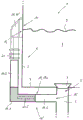
Fig. 1 shows a water trough according to the invention with an overflow mechanism according to the invention in a schematic partial sectional view.
Fig. 2 shows the overflow head of the overflow mechanism of the invention in a perspective view.
Fig. 3 shows the overflow head of fig. 2 in another perspective view.
FIG. 4 shows a different view of the overflow head of FIGS. 2 and 3;
fig. 5 schematically shows an alternative embodiment of the sink of fig. 1 in partial cross-section.
Fig. 6 shows an alternative to a sink with an overflow recess.
Figure 7 shows another alternative to a gutter with a separate drain opening.
Detailed Description
In fig. 1 a sink, in particular a kitchen sink, is shown in a partially sectional schematic view, which is generally designated by reference numeral 1. The tank 1 comprises at least one wash tank 2, only the lower corner of which is shown here, comprising a tank wall 3 and a tank bottom 4. An outflow opening is provided in the tank bottom 4 at 5, which is in fluid communication with a tank outlet 6, as is known per se. In the region of the outflow opening 5, a closure or valve plug 7 is provided, which in the exemplary embodiment shown closes the outflow opening 5 in a fluid-tight manner, so that no water can flow away from the sink 2 via the outflow opening 5. This results in the flushing water contained in the washer tub 2 reaching the schematically shown water level 9. The water level 9 is at the level of an opening 10 in the tank wall 3, which opening 10 can also be referred to as an overflow. The opening 10 is not visible in fig. 1 because of the chosen view.
In the region of the opening 10, a so-called overflow head 11 of an overflow means 12 known per se is fitted externally on the tank wall 3, through which overflow means 12 water 8 can flow from the washer tank 2 to the sump outlet 6 when the water level 9 in the washer tank 2 reaches or exceeds a certain level. The overflow 12 comprises, in addition to the overflow head 11, an inlet 13 in the region of the overflow head 11, which inlet 13 communicates with the opening 10 in the tank wall 3 of the washer tank 2. Around the inlet opening 13, a seal is usually provided in order to seal the overflow head 11 in a fluid-tight manner against the tank wall 3. The seal is not visible in fig. 1. According to fig. 1, a curved overflow pipe 14 is connected to the overflow head 11, which overflow pipe defines an outflow opening 15 at its end facing away from the overflow head 11, through which outflow opening the overflow means 12 opens into the tank outlet 6. The inflow opening 13, the overflow head 11, the overflow pipe 14 and the outflow opening 15 in this way define a flow channel 14a from the opening 10 in the wall 3 of the washer tub 2 to the tub outlet 6, so that water 8 can flow out of the washer tub 2 via the overflow 12 when the water level 9 reaches or exceeds a certain water level (a certain level), as described.
The embodiment described so far in connection with fig. 1 is known per se and is commonly used in commercially available (kitchen) sinks such as the sink 1 shown. The invention now relates to improvements in the area of the overflow 12, in particular the overflow head 11, which will be described in more detail in connection with the following figures.
Fig. 2 shows an overflow head 11' of the overflow mechanism of the invention in a general perspective view, which is not further shown in fig. 2. For further structural design features of the overflow mechanism, see fig. 1, which has already been described in detail.
The overflow head 11' according to fig. 2 also comprises the already described substantially rectangular inlet opening 13, which is surrounded by a correspondingly shaped sealing surface 16. Approximately in the center of the inlet opening 13 (which is also slightly funnel-shaped and narrows inwards), an approximately cylindrical reinforcing structure 17 is provided centrally, which forms a mounting opening 18 for fixing the overflow head 11' in the region of the tank wall 3 (see fig. 1). In the lower boundary surface 19 of the inflow opening 13, four recesses or bores 20.1 to 20.4 are provided, which extend parallel to one another through the pipe connection 21 of the overflow head 11'. The recesses or openings 20.1 to 20.4 each define a flow channel section of the overflow 12 (see fig. 1) and each have a substantially circular cross section, as can be seen particularly clearly from the other perspective views in fig. 3. The pipe connection 21 of the overflow head 11' has a male shaped structure which can be used for mounting a sleeved pipe or hose (not shown) or for reinforcement purposes.
Fig. 3 shows the overflow head 11' in a further perspective view from obliquely below, so that the structure and arrangement of the recesses/holes or flow channel sections 20.1-20.4 can be clearly seen. They are arranged side by side in a line as already described (not shown in terms of their virtual center points) and each have approximately the same diameter D. The invention is in no way limited to the arrangement, number or dimensioning of the notches/holes 20.1-20.4 shown here.
For example, the notches/holes 20.1-20.4 may also have different diameters D and there may be more or less than the four notches/holes 20.1-20.4 shown. In addition, they can be arranged relative to one another according to other geometric shapes, for example offset, in a meandering manner, in the form of squares, triangles or the like, or, for example, can be provided with only one such recess. It is important in any case that the recess or recesses have a substantially circular diameter, although the pipe connection 21 of the overflow head 11 or its inflow opening 13 has a different shape (oval or rectangular). The applicant has found that, due to the presence of the circular flow channel section, a much improved flow of overflow water occurs in the region of the overflow means, similar to: the water flows out better when the suspended bottle is simultaneously rotated about the longitudinal axis of the bottle.
The recesses/bores 20.1-20.4 can have a widened end in the region of the inlet opening 13 and/or in the region of the free end (lower end) of the pipe connection 21, as is shown by way of example in fig. 3 at 22.4 for the bore 20.4.
Fig. 4 shows further views of the overflow head 11' according to fig. 2 and 3.
In the partial drawing 4a), the overflow head 11' is shown in a side view corresponding to fig. 1. This is not further described here. It can be seen that the inlet 13, as described further above in connection with fig. 2, tapers in a funnel shape from the sealing surface 16 inwards (to the left in fig. 4 a).
In the partial drawing 4b), the overflow head 11' is shown in a view from the front. It can clearly be seen that there are mounting holes 18 and a reinforcing structure 17 surrounding the sealing surface 16.
Fig. 4c) shows the position of the section line B-B, which corresponds to the overflow head 11' in the section according to fig. 4 d). As can be clearly seen in fig. 4 d): the position and configuration of the flow channel sections or gaps/holes 20.1-20.4, which have approximately the same diameter D, can be the same for all four holes 20.1-20.4, which is not visible in fig. 4D) because of the selected sectional view. The reference symbol L designates the axial length of the flow channel section or the recess/bore 20.1-20.4, which may also be the same for all four flow channel sections and corresponds substantially to the total axial length L of the pipe connection 21 from the inflow opening 13 to its free end.
Fig. 5 schematically shows an alternative embodiment of the overflow mechanism according to the invention (indicated by reference numeral 12 'in fig. 5), in which (another) flow channel section is provided in the region of the overflow pipe 14 instead of or in addition to the flow channel section with a circular cross section formed in the region of the overflow head 11, 11'. In particular, the further flow path section is indicated by 20.5 and is arranged in the region of an elbow 14.1 which connects, in its extension, a first pipe piece 14.2 connected to a pipe connection 21 of the overflow head 11, 11 'with a second pipe piece 14.3 connected to the sink outlet 6 and defining the outflow 15 of the overflow 12'. The elbow or bend 14.1 is shown in dotted lines in figure 5. Instead of the further flow channel section 20.5 shown, a plurality of such sections can also be arranged opposite one another in virtually any arrangement, as already indicated with further reference to fig. 2 and 3. It is also possible here for the at least one further channel section 20.5 to extend completely through the elbow 14.1, i.e. also through a corner thereof.
As is known to the person skilled in the art, the at least one flow channel section 20.5 can alternatively also be arranged in the region of the first tube part 14.2 and/or the second tube part 14.3. In all cases, the improvements proposed here can be implemented in the (sink) overflow area, also in existing sinks by correspondingly adapting the existing overflow mechanism, by: for example, the corresponding pipe or elbow piece 14.1-4.3 is subsequently inserted or the corresponding insert piece is inserted into the existing overflow. The same applies in connection with the overflow head 11', which can replace the overflow head 11 known in the art.
Without being limited thereto, it has proven to be particularly advantageous if the diameter D of the recess/hole is in the range from 2mm to 35mm, wherein correspondingly many recesses are provided when the diameter D is small. Applicants have found that the smallest cross-section taken together with all the gaps or holes should be about 150mm2To about 200mm2In the range, preferably about 175mm2. The preferred length L of the notch/hole is about 5mm to 150mm and may depend on the selected diameter D: l ═ f · D, where f ═ f (D) can take values between about 2 and about 5.
The invention is not limited to use in the field of launders, but it may alternatively or additionally be used in the area of so-called overflow sumps or separate downcomers.
Fig. 6 shows a water reservoir 1 'with an overflow recess 2'. The overflow sump 2 ' has (in the installed state) a horizontally arranged opening 10 ' below which an overflow mechanism according to the invention (not shown here) is or can be installed, in order to also use its advantages for such a sink 1 '.
Fig. 7 shows a basin 1 "with a separate drain opening 2". The drain 2 "also has (in the mounted state) a horizontally arranged opening 10" below which an overflow mechanism according to the invention (not shown here) is mounted or mountable, so that its advantages can also be used for such a sink 1 ".
It is clear that the overflow mechanism according to the invention can also be additionally provided in the region of the basin 2 in the sinks 1', 1 ″ according to fig. 6 or 7, as described above.
Claims (22)
1. Overflow mechanism (12,12 ') for a sink (1, 1') having at least one inlet opening (13) intended for mounting on a basin (2) or an overflow recess (2 ') or a separate drain opening (2') of the sink (1,1 ') and an outlet opening (15) intended for mounting on a water outlet opening (6) or a ventilation valve of the sink (1, 1'), wherein a flow channel (14a) for a fluid (8) is provided between the inlet opening (13) and the outlet opening (15), wherein at least one section (20.1-20.4; 20.5) is provided in the flow channel (14a), which flow channel (14a) has a substantially circular cross-section in said section,
it is characterized in that the utility model is characterized in that,
a plurality of such sections (20.1-20.4) with a circular cross section are arranged in parallel within the flow channel (14a), the sections (20.1-20.4) being arranged in side-by-side fashion, in triangular fashion, in staggered fashion or in meandering fashion in each case with respect to the position of the center point of the sections.
2. Overflow mechanism (12, 12') according to claim 1, characterized in that the flow channel (14a) has a constant cross section in said section.
3. Overflow mechanism (12, 12') according to claim 1, characterized in that the flow channel (14a) has at least one narrowing of its cross-section in the flow direction of the fluid (8) in said section.
4. Overflow means (12, 12') according to one of claims 1 to 3, characterized in that the section has a length L, for which L ≧ f × D, 2 ≦ f ≦ 5, where D denotes the diameter of the section.
5. Overflow mechanism (12, 12') according to claim 1, characterized in that the sum of the cross-sections of said sections (20.1-20.4) is at least about 175mm2。
6. Overflow mechanism (12, 12') according to one of claims 1 to 3, characterized in that the sections (20.1-20.4) are constructed substantially identically to each other.
7. Overflow mechanism (12, 12') according to one of claims 1 to 3, characterized in that said at least one section (20.1-20.4) is arranged in the region of the inlet opening (13).
8. Overflow means (12,12 ') according to one of claims 1 to 3, characterized in that said at least one section (20.1-20.4) is arranged in the region of an overflow head (11') of the overflow means.
9. Overflow mechanism (12, 12') according to one of claims 1 to 3, characterized in that said at least one section is arranged in the area of the outflow opening (15).
10. Overflow mechanism (12, 12') according to one of claims 1 to 3, characterized in that the at least one section (20.5) is arranged in the area of an elbow (14.1) of the flow channel (14a), the elbow (14.1) turning a first section (14.2) of the flow channel (14a) which is vertical when installed to a second section (14.3) of the flow channel (14a) which is horizontal when installed.
11. Overflow mechanism (12, 12') according to claim 10, characterized in that said at least one section (20.5) is arranged in the area of said second section (14.3).
12. Overflow mechanism (12, 12') according to claim 4, characterized in that D is 2mm ≦ D ≦ 35 mm.
13. A sink (1,1 ') having at least one overflow (12, 12'),
the basin comprises an opening (10) in the side wall (3) of the washer tub (2) or in the horizontal plane of the basin, which opening is located in the area of the overflow pocket (2 ') or the separate drain opening (2'),
the opening (10) being in fluid communication with the water outlet (6) of the basin (1) via the overflow means (12, 12'),
it is characterized in that the utility model is characterized in that,
the overflow means (12, 12') being constructed according to one of claims 1 to 12.
14. A retrofit for a sink (1,1 ') with an overflow mechanism (12,12 '), the sink (1,1 ') comprising an opening (10) in a side wall (3) of a washer tub (2) or an opening in a horizontal plane of the sink, the opening in the horizontal plane of the sink being located in the area of an overflow pocket (2 ') or a separate drain opening (2 '),
the opening (10) being in fluid communication with the water outlet (6) of the basin (1) via the overflow means (12, 12'),
the retrofit part is designed to be inserted into the flow channel (14a) of the overflow (12, 12') between the inlet (13) and the outlet (15), wherein,
a) the outer contour of the retrofit part substantially corresponds to the inner contour of the overflow (12, 12') in a region, and the retrofit part has at least one recess, the inner contour of which has a substantially circular cross section, or
b) The retrofit forms at least a partial section of the flow channel (14 a).
15. The fitment of claim 14 wherein the at least one notch defines a flow path segment.
16. The fitting according to claim 15, characterized in that the flow channel (14a) has a constant cross section in said channel section.
17. The retrofit according to claim 15, characterized in that the flow channel (14a) has at least one constriction of its cross section in the flow direction of the fluid in the flow channel section.
18. The retrofit kit of any of claims 15 to 17, wherein the runner section has a length L, for which L ≧ fxd, 2 ≦ f ≦ 5, where D denotes the diameter of the runner section.
19. A retrofit part according to any of the claims 15 to 17, characterized in that a plurality of such flow channel sections are arranged in parallel in the flow channel (14 a).
20. The fitting of claim 19, wherein the sum of the cross-sections of the runner segments is at least about 175mm2。
21. The fitting according to claim 19, characterized in that the flow path segments are arranged in a side-by-side manner, in a triangular manner, in a staggered manner or in a meandering manner.
22. The fitting according to claim 19, characterized in that the flow channel sections are formed substantially identically to one another.
Applications Claiming Priority (2)
| Application Number | Priority Date | Filing Date | Title |
|---|---|---|---|
| DE102016100338.7 | 2016-01-11 | ||
| DE102016100338.7A DE102016100338A1 (en) | 2016-01-11 | 2016-01-11 | Overflow for a pool, especially sinks |
Publications (2)
| Publication Number | Publication Date |
|---|---|
| CN106958274A CN106958274A (en) | 2017-07-18 |
| CN106958274B true CN106958274B (en) | 2020-12-04 |
Family
ID=57286283
Family Applications (1)
| Application Number | Title | Priority Date | Filing Date |
|---|---|---|---|
| CN201611129358.XA Expired - Fee Related CN106958274B (en) | 2016-01-11 | 2016-12-09 | Overflow mechanism for sink basin, especially sink |
Country Status (4)
| Country | Link |
|---|---|
| EP (1) | EP3199715B1 (en) |
| CN (1) | CN106958274B (en) |
| CH (1) | CH711775B1 (en) |
| DE (1) | DE102016100338A1 (en) |
Families Citing this family (2)
| Publication number | Priority date | Publication date | Assignee | Title |
|---|---|---|---|---|
| JP6490168B1 (en) * | 2017-09-12 | 2019-03-27 | 吉本産業株式会社 | Basin |
| CN111677060A (en) * | 2020-07-07 | 2020-09-18 | 临海市朵纳卫浴有限公司 | Water tank for splicing rock plate table top |
Family Cites Families (11)
| Publication number | Priority date | Publication date | Assignee | Title |
|---|---|---|---|---|
| US746419A (en) * | 1902-10-13 | 1903-12-08 | James J Wade | Basin or bath fitting. |
| DE1961497U (en) * | 1967-01-07 | 1967-06-01 | Franz Scheffer Fa | ON-SITE ADAPTABLE DRAIN FITTING. |
| BE795796A (en) * | 1972-03-27 | 1973-06-18 | Gebert & Cie | DISCHARGE DEVICE FOR TUBS |
| DE9202872U1 (en) * | 1992-03-05 | 1992-05-21 | Fa. Franz Viegener Ii, 5952 Attendorn, De | |
| CN2312256Y (en) * | 1997-11-03 | 1999-03-31 | 和宏实业有限公司 | Water overflow means for washbasin |
| US6249920B1 (en) * | 1998-05-07 | 2001-06-26 | Mcguire Manufacturing Co., Inc. | Grid drain |
| US20080196161A1 (en) * | 2004-10-22 | 2008-08-21 | Wcm Industries, Inc. | Flexible Bathtub Waste Pipe Assembly for Bathtubs and the Like |
| DE102007014839A1 (en) * | 2007-03-28 | 2008-10-02 | Niro-Plan Ag | kitchen sink |
| JP5756937B2 (en) * | 2009-09-30 | 2015-07-29 | 丸一株式会社 | Remote-controlled drain plug device |
| CN101824844A (en) * | 2010-04-01 | 2010-09-08 | 宁波搏盛阀门管件有限公司 | Sink and sink overflow device |
| CN202018306U (en) * | 2011-03-29 | 2011-10-26 | 温州市捷达石化仪表有限公司 | Porous balance flow meter |
-
2016
- 2016-01-11 DE DE102016100338.7A patent/DE102016100338A1/en not_active Withdrawn
- 2016-01-15 CH CH00058/16A patent/CH711775B1/en not_active IP Right Cessation
- 2016-11-09 EP EP16197956.2A patent/EP3199715B1/en active Active
- 2016-12-09 CN CN201611129358.XA patent/CN106958274B/en not_active Expired - Fee Related
Also Published As
| Publication number | Publication date |
|---|---|
| CN106958274A (en) | 2017-07-18 |
| EP3199715A3 (en) | 2017-10-18 |
| EP3199715A2 (en) | 2017-08-02 |
| DE102016100338A1 (en) | 2017-07-13 |
| CH711775B1 (en) | 2017-05-15 |
| EP3199715B1 (en) | 2020-03-25 |
Similar Documents
| Publication | Publication Date | Title |
|---|---|---|
| US20190055723A1 (en) | Overflow | |
| US20150299994A1 (en) | Plumbing Overflow | |
| TW201632690A (en) | Storage tank, siphon-style drainage system and outflow pipe connection member | |
| CN106958274B (en) | Overflow mechanism for sink basin, especially sink | |
| EP3712338A1 (en) | Flush toilet | |
| JP5291404B2 (en) | Siphon drainage system | |
| JP5756938B2 (en) | Drainage pipes and drainage traps for drainage equipment | |
| TW201638438A (en) | Storage tank, siphon-style drainage system and outflow pipe connection member | |
| JP4039082B2 (en) | Drain structure of bathroom unit | |
| JP4617415B2 (en) | Drain trap | |
| CN109610589A (en) | From dredging closestool | |
| JP2020029708A (en) | Drain trap | |
| JP5151498B2 (en) | Bathroom drainage equipment | |
| CN211499089U (en) | Independent water pressure flushing system and intelligent closestool | |
| JP6820173B2 (en) | Drain trap | |
| CN110337517B (en) | Drainage structure and siphon drainage system | |
| DK181206B1 (en) | An extraction unit and use of an extraction unit | |
| JP2007197943A (en) | Drain trap | |
| JP7024164B2 (en) | Drainage port member and drainage piping structure | |
| CN209082623U (en) | A kind of novel sink | |
| JP6854078B2 (en) | Water spouting device and hand washing device | |
| CN204826131U (en) | Pan closet | |
| JP6659207B2 (en) | Flush toilet | |
| JP4605081B2 (en) | Bathroom drainage structure | |
| JP4442629B2 (en) | Drain structure of bathroom unit |
Legal Events
| Date | Code | Title | Description |
|---|---|---|---|
| PB01 | Publication | ||
| PB01 | Publication | ||
| REG | Reference to a national code |
Ref country code: HK Ref legal event code: DE Ref document number: 1235439 Country of ref document: HK |
|
| SE01 | Entry into force of request for substantive examination | ||
| SE01 | Entry into force of request for substantive examination | ||
| GR01 | Patent grant | ||
| GR01 | Patent grant | ||
| CF01 | Termination of patent right due to non-payment of annual fee |
Granted publication date: 20201204 Termination date: 20211209 |
|
| CF01 | Termination of patent right due to non-payment of annual fee |