EP3196972A1 - Batteriesensorenvorrichtung - Google Patents
Batteriesensorenvorrichtung Download PDFInfo
- Publication number
- EP3196972A1 EP3196972A1 EP15841571.1A EP15841571A EP3196972A1 EP 3196972 A1 EP3196972 A1 EP 3196972A1 EP 15841571 A EP15841571 A EP 15841571A EP 3196972 A1 EP3196972 A1 EP 3196972A1
- Authority
- EP
- European Patent Office
- Prior art keywords
- board
- terminal
- battery
- sensor device
- clamp part
- Prior art date
- Legal status (The legal status is an assumption and is not a legal conclusion. Google has not performed a legal analysis and makes no representation as to the accuracy of the status listed.)
- Withdrawn
Links
- 238000012546 transfer Methods 0.000 claims abstract description 14
- 239000011347 resin Substances 0.000 claims description 30
- 229920005989 resin Polymers 0.000 claims description 30
- 239000002184 metal Substances 0.000 claims description 20
- 229910052751 metal Inorganic materials 0.000 claims description 20
- 238000010586 diagram Methods 0.000 description 42
- 238000001514 detection method Methods 0.000 description 15
- 239000004519 grease Substances 0.000 description 8
- 229910001369 Brass Inorganic materials 0.000 description 2
- 239000010951 brass Substances 0.000 description 2
- RYGMFSIKBFXOCR-UHFFFAOYSA-N Copper Chemical compound [Cu] RYGMFSIKBFXOCR-UHFFFAOYSA-N 0.000 description 1
- 239000004593 Epoxy Substances 0.000 description 1
- 239000000853 adhesive Substances 0.000 description 1
- 230000001070 adhesive effect Effects 0.000 description 1
- 238000009529 body temperature measurement Methods 0.000 description 1
- 239000004020 conductor Substances 0.000 description 1
- 239000011889 copper foil Substances 0.000 description 1
- 230000006866 deterioration Effects 0.000 description 1
- 238000009429 electrical wiring Methods 0.000 description 1
- 230000002349 favourable effect Effects 0.000 description 1
- 239000011521 glass Substances 0.000 description 1
- 238000009434 installation Methods 0.000 description 1
- WABPQHHGFIMREM-UHFFFAOYSA-N lead(0) Chemical compound [Pb] WABPQHHGFIMREM-UHFFFAOYSA-N 0.000 description 1
- 238000005259 measurement Methods 0.000 description 1
- 238000010297 mechanical methods and process Methods 0.000 description 1
- 238000000034 method Methods 0.000 description 1
- 238000012986 modification Methods 0.000 description 1
- 230000004048 modification Effects 0.000 description 1
- 238000000465 moulding Methods 0.000 description 1
- 238000012545 processing Methods 0.000 description 1
- 230000004043 responsiveness Effects 0.000 description 1
- 238000005476 soldering Methods 0.000 description 1
- XLYOFNOQVPJJNP-UHFFFAOYSA-N water Substances O XLYOFNOQVPJJNP-UHFFFAOYSA-N 0.000 description 1
- 238000003466 welding Methods 0.000 description 1
Images


Classifications
-
- G—PHYSICS
- G01—MEASURING; TESTING
- G01K—MEASURING TEMPERATURE; MEASURING QUANTITY OF HEAT; THERMALLY-SENSITIVE ELEMENTS NOT OTHERWISE PROVIDED FOR
- G01K1/00—Details of thermometers not specially adapted for particular types of thermometer
- G01K1/14—Supports; Fastening devices; Arrangements for mounting thermometers in particular locations
-
- G—PHYSICS
- G01—MEASURING; TESTING
- G01K—MEASURING TEMPERATURE; MEASURING QUANTITY OF HEAT; THERMALLY-SENSITIVE ELEMENTS NOT OTHERWISE PROVIDED FOR
- G01K7/00—Measuring temperature based on the use of electric or magnetic elements directly sensitive to heat ; Power supply therefor, e.g. using thermoelectric elements
- G01K7/16—Measuring temperature based on the use of electric or magnetic elements directly sensitive to heat ; Power supply therefor, e.g. using thermoelectric elements using resistive elements
- G01K7/22—Measuring temperature based on the use of electric or magnetic elements directly sensitive to heat ; Power supply therefor, e.g. using thermoelectric elements using resistive elements the element being a non-linear resistance, e.g. thermistor
-
- G—PHYSICS
- G01—MEASURING; TESTING
- G01R—MEASURING ELECTRIC VARIABLES; MEASURING MAGNETIC VARIABLES
- G01R15/00—Details of measuring arrangements of the types provided for in groups G01R17/00 - G01R29/00, G01R33/00 - G01R33/26 or G01R35/00
- G01R15/14—Adaptations providing voltage or current isolation, e.g. for high-voltage or high-current networks
-
- G—PHYSICS
- G01—MEASURING; TESTING
- G01R—MEASURING ELECTRIC VARIABLES; MEASURING MAGNETIC VARIABLES
- G01R31/00—Arrangements for testing electric properties; Arrangements for locating electric faults; Arrangements for electrical testing characterised by what is being tested not provided for elsewhere
- G01R31/36—Arrangements for testing, measuring or monitoring the electrical condition of accumulators or electric batteries, e.g. capacity or state of charge [SoC]
- G01R31/3644—Constructional arrangements
-
- H—ELECTRICITY
- H01—ELECTRIC ELEMENTS
- H01M—PROCESSES OR MEANS, e.g. BATTERIES, FOR THE DIRECT CONVERSION OF CHEMICAL ENERGY INTO ELECTRICAL ENERGY
- H01M10/00—Secondary cells; Manufacture thereof
- H01M10/42—Methods or arrangements for servicing or maintenance of secondary cells or secondary half-cells
- H01M10/4285—Testing apparatus
-
- H—ELECTRICITY
- H01—ELECTRIC ELEMENTS
- H01M—PROCESSES OR MEANS, e.g. BATTERIES, FOR THE DIRECT CONVERSION OF CHEMICAL ENERGY INTO ELECTRICAL ENERGY
- H01M10/00—Secondary cells; Manufacture thereof
- H01M10/42—Methods or arrangements for servicing or maintenance of secondary cells or secondary half-cells
- H01M10/48—Accumulators combined with arrangements for measuring, testing or indicating the condition of cells, e.g. the level or density of the electrolyte
- H01M10/486—Accumulators combined with arrangements for measuring, testing or indicating the condition of cells, e.g. the level or density of the electrolyte for measuring temperature
-
- H—ELECTRICITY
- H01—ELECTRIC ELEMENTS
- H01M—PROCESSES OR MEANS, e.g. BATTERIES, FOR THE DIRECT CONVERSION OF CHEMICAL ENERGY INTO ELECTRICAL ENERGY
- H01M2220/00—Batteries for particular applications
- H01M2220/20—Batteries in motive systems, e.g. vehicle, ship, plane
-
- Y—GENERAL TAGGING OF NEW TECHNOLOGICAL DEVELOPMENTS; GENERAL TAGGING OF CROSS-SECTIONAL TECHNOLOGIES SPANNING OVER SEVERAL SECTIONS OF THE IPC; TECHNICAL SUBJECTS COVERED BY FORMER USPC CROSS-REFERENCE ART COLLECTIONS [XRACs] AND DIGESTS
- Y02—TECHNOLOGIES OR APPLICATIONS FOR MITIGATION OR ADAPTATION AGAINST CLIMATE CHANGE
- Y02E—REDUCTION OF GREENHOUSE GAS [GHG] EMISSIONS, RELATED TO ENERGY GENERATION, TRANSMISSION OR DISTRIBUTION
- Y02E60/00—Enabling technologies; Technologies with a potential or indirect contribution to GHG emissions mitigation
- Y02E60/10—Energy storage using batteries
Definitions
- the present invention relates to a battery sensor device for detecting a state of a battery.
- Detection of a battery capacity (SOC: State of Charge) or a battery deterioration state (SOH: State of Health) of a battery (for example, a lead battery) mounted on a vehicle is performed.
- SOC State of Charge
- SOH Battery deterioration state
- a battery sensor device for detecting these is disclosed in, for example, Patent Literature 1 and Patent Literature 2.
- Patent Literature 1 discloses a battery sensor device capable of accurately detecting the temperature of a battery by providing a temperature sensor which detects the temperature of a battery close to a terminal of the battery.
- Patent Literature 2 discloses a battery sensor device capable of accurately detecting the temperature of a battery by directly providing a temperature sensor which detects the temperature of the battery on the terminal body.
- the present invention provides a battery sensor device capable of accurately detecting a temperature of a battery and having excellent assembling properties.
- a battery sensor device includes a terminal, bus bars, a board, a temperature sensor, and a heat transfer member.
- the terminal includes a clamp part fitted to a terminal of the battery.
- a load-side terminal is installed on the bus bars.
- the bus bars electrically connect the clamp part and the load-side terminal via a shunt resistance.
- the board is electrically connected to the bus bars to overlap the bus bars, and includes a protruding part which protrudes from the bus bars toward the clamp part.
- the temperature sensor is installed on the protruding part of a surface which faces the bus bars of the board.
- the heat transfer member is provided between the temperature sensor and the terminal.
- a battery sensor device includes a clamp part which is fitted to a terminal of a battery, a load-side terminal, bus bars, a temperature sensor which detects a temperature, a board, and a sealer.
- the bus bars electrically connect the clamp part and the load-side terminal via a shunt resistance.
- the temperature sensor is installed on the board.
- the board is fastened to the metal part between the clamp part and the shunt resistance.
- the sealer covers the board.
- the temperature sensor is installed on the board to be separated from the metal part.
- the fastener between the board and the metal part is disposed outside the first circle which is centered on the center of the clamp part, and which has the shortest distance from the center of the clamp part to the sealer as a radius.
- the fastener is disposed inside a second circle which is centered on the center of the clamp part and which has a distance as a radius obtained by adding a length three times the maximum bearing surface width of the fastener to the shortest distance from the center of the clamp part to the sealer.
- the fastener is disposed inside the second circle which has a distance as a radius obtained by adding a length three times the maximum width of the contact surface between the board and the metal part in the fastener, to a shortest distance from the center of the clamp part to the sealer.
- a battery sensor device capable of accurately detecting a temperature of a battery and having excellent assembling properties.
- Patent Literature 2 since it is necessary to provide a structure (for example, a structure or the like to be fixed via an elastic body) for bringing the temperature sensor into close contact with the terminal body, the structure becomes complicated.
- FIG. 1 is a perspective diagram illustrating a state in which battery sensor device 100 according to exemplary embodiment 1 of the present invention is connected to battery 1.
- FIG. 2 is a top surface diagram of FIG. 1 .
- battery 1 is provided with plus terminal 2 and minus terminal 3.
- clamp part 11 (refer to FIG. 3 ) which is described later is fitted to minus terminal 3, and is fastened to minus terminal 3 by nut 13 and bolt 14 (refer to FIG. 3 ) which are described later.
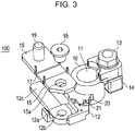
- FIG. 3 is an exploded perspective diagram illustrating a state before attaching bus bars 15 and 16 and shunt resistance 17 to terminal 10.
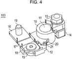
- FIG. 4 is a perspective diagram illustrating a state in which bus bars 15 and 16 and shunt resistance 17 are attached to terminal 10.
- FIG. 5 is a top surface diagram of FIG. 4 .
- terminal 10 (an example of a metal part) is formed of a metal member such as brass, for example, and includes clamp part 11 and attachment part 12. As illustrated in FIG. 3 , attachment part 12 protrudes from the side surface of clamp part 11 and is joined to clamp part 11.
- the metal member which forms terminal 10 is not limited to brass and may be another metal.
- Clamp part 11 is fitted to minus terminal 3 of battery 1.
- Clamp part 11 grips minus terminal 3 of battery 1 to fasten by interposing clamp part 11 using bolt 13 and nut 14.
- Bus bars 15 and 16, shunt resistance 17, and board 23 are attached to attachment part 12.
- a current from the battery 1 flows via terminal 10 to bus bar 15, shunt resistance 17, and bus bar 16.
- Hole portion 15a through which bolt 18 is inserted is formed in bus bar 15.
- bus bar 15 is fastened to attachment part 12 of terminal 10 by bolt 18; however, the configuration is not limited thereto.
- bus bar 15 may be electrically and mechanically connected to attachment part 12 of terminal 10 by welding, caulking, rivets, or the like.
- Bus bar 16 is provided with, for example, vehicle load-side terminal 19 which is grounded to a body (not illustrated) of the vehicle.
- Shunt resistance 17 is provided between bus bar 15 and bus bar 16.
- joint portion 12a which joins attachment part 12 to bus bar 15 is formed on attachment part 12.
- Hole portion 12b is formed in joint portion 12a.
- bolt 18 By inserting bolt 18 into hole portion 12b of joint portion 12a and hole portion 15a of bus bar 15, bus bar 15 is attached in contact with joint portion 12a as illustrated in FIGS. 4 and 5 .
- Joint portion 12a is formed of metal.
- support portion 12c which is adjacent to joint portion 12a is provided on attachment part 12.
- Support portion 12c is a portion of terminal 10, and is a conductor. There is a gap between support portion 12c and bus bar 16, and support portion 12c is not electrically connected to bus bar 16.
- Support portion 12c is integrated with resin mold 31 when resin mold 31 which is described later is molded, and serves a role of holding bus bar 16. Since support portion 12c increases the mechanical reliability, there is not influence on the temperature measurement.
- joint portion 20 which joins attachment part 12 to board 23 is formed on attachment part 12. Hole portion 21 through which screw 30 (refer to FIG. 9 ) which is described later is inserted is formed in joint portion 20. Joint portion 20 is formed of metal. Detailed description of the attachment of board 23 to joint portion 20 will be given later.
- connector portion 22 is attached to attachment part 12.
- Connector portion 22 is connected to plus terminal 2 of battery 1 (not illustrated).
- Connector portion 22 outputs information indicating a current, a voltage, a temperature, and the like which are detected by board 23 which is described later to a CPU (Central Processing Unit), an ECU (Engine Control Unit), or the like, which is not illustrated.
- CPU Central Processing Unit
- ECU Engine Control Unit
- bus bars 15 and 16 and shunt resistance 17 are attached to attachment part 12 as illustrated in FIGS. 4 and 5 , board 23 is fastened to joint portion 20 of attachment part 12. At this time, board 23 is connected to current detection terminals 18a to 18d which are connected to bus bars 15 and 16. Accordingly, board 23 detects a voltage difference across shunt resistance 17.
- bus bars 15 and 16 are provided with two current detection terminals each for a total of four current detection terminals; however, a total of two current detection terminals may be provided, one each before and after shunt resistance 17. In other words, either current detection terminal 18a or the current detection terminal 18b may be provided on bus bar 15, and either current detection terminal 18c or current detection terminal 18d may be provided on bus bar 16.
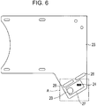
- FIG. 6 is a plan view illustrating a first surface of board 23.
- the first surface refers to a surface of the side which faces attachment part 12 when board 23 is attached to attachment part 12.
- Board 23 is, for example, a glass epoxy board-shaped member. As illustrated in FIGS. 6 and 9 , board 23 has a shape protruding to clamp part 11 side, and on the first surface of the projecting portion, thermistor 24 is attached as a temperature sensor for measuring the temperature of battery 1. Thermistor 24 is less susceptible to the influence of the temperature of shunt resistance 17 and is disposed in a position closer to minus terminal 3 in order to enable more accurate temperature detection. Details of the disposition position of thermistor 24 will be described later using FIGS. 15 and 16 .
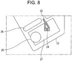
- FIGS. 7 and 8 are enlarged diagrams of region A of FIG. 6 .
- via 25 which communicates with the inside of board 23 is formed, and the information of the temperature which is measured by thermistor 24 is output via via 25 and a wiring (not illustrated) which is inside board 23 which is connected to via 25, and is output to the circuit.
- electric pattern (pattern wiring) 26 is formed on board 23, and the information of the temperature which is measured by thermistor 24 is output to an output circuit via electric pattern 26 and a wiring (not illustrated) on the first surface of board 23 which is connected to electric pattern 26.
- the output circuit outputs information of the temperature which is input from thermistor 24 to the CPU, the ECU, or the like via connector portion 22.
- board 23 includes a voltage sensor (not illustrated) which detects the voltage of battery 1, and current sensor (not illustrated) which detects the current based on the voltage across both terminals of shunt resistance 17. Information of the voltage and the current which are detected by these sensors is also output to the CPU, the ECU, or the like via the output circuit and connector portion 22.
- thermal conduction pattern 27 (heat transfer member) is formed on the first surface of board 23.
- Thermal conduction pattern 27 is formed of a member (for example, copper foil) having a thermal conductivity higher than that of board 23.
- thermal conduction pattern 27 is formed close to thermistor 24 so as not to come into contact with thermistor 24.
- thermal conduction pattern 27 is formed close to thermistor 24 and electric pattern 26 so as not to come into contact with thermistor 24 and electric pattern 26.
- a clearance of a predetermined length is provided between thermal conduction pattern 27 and thermistor 24.
- Thermal conduction pattern 27 may be formed to extend along at least one side of thermistor 24.
- the length of the clearance between thermistor 24 and thermal conduction pattern 27 may be shorter than the shortest width among the widths in the planar direction of thermistor 24.
- thermal conduction pattern 27 and ground (GND) of thermistor 24 are separated.
- thermal conduction pattern 27 and GND of thermistor 24 match circuit-wise, it is also possible to eliminate the clearance therebetween and to render thermal conduction pattern 27 and the ground pattern of thermistor 24 common.
- pattern cut portion 28 in which a portion of board 23 is cut out is formed on board 23.
- Pattern cut portion 28 prevents the heat from shunt resistance 17 from transferring to thermistor 24.
- the thermal capacity of the area of board 23 on which thermistor 24 rests is reduced, and the responsiveness of the temperature is increased.
- hole portion 29 through which screw 30 (refer to FIG. 5 ) (heat transfer member) which is described later is inserted is formed in board 23.
- FIG. 9 is a diagram illustrating a state in which board 23 is fixed to attachment part 12 by a screw.
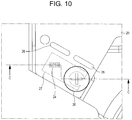
- FIG. 10 is an enlarged diagram of region B of FIG. 9 .
- Fig. 11 is a sectional diagram taken along the C-C line of FIG. 10 .
- screw 30 is inserted into hole portion 29 of board 23 and hole portion 21 (refer to FIG. 5 ) which is formed in joint portion 20 of attachment part 12, whereby board 23 is attached in contact with joint portion 20. Due to the screwing, as illustrated in FIG. 11 , a portion of thermal conduction pattern 27 which is formed on board 23 and attachment part 12 (joint portion 20) are brought into close contact. Accordingly, the heat from attachment part 12 is easily conducted to thermal conduction pattern 27. Thermal conduction pattern 27 may be close to attachment part 12 (joint portion 20) without coming in contact with attachment part 12 (joint portion 20).
- board 23 is fastened to joint portion 20 by screw 30; however, the configuration is not limited thereto.
- board 23 may be connected to joint portion 20 by a fixing method such as thermal caulking in which a boss is passed through the board and is welded using heat, an adhesive, or the like. Board 23 may be connected to joint portion 20 by another mechanical method.
- thermistor 24 on board 23 is disposed to be separated from attachment part 21 (joint portion 20). As illustrated in FIG. 9 , board 23 covers bus bar 15 and shunt resistance 17.
- the heat of minus terminal 3 is conducted from attachment part 12 which is a portion of terminal 10 to thermal conduction pattern 27.
- the temperature of the head which is conducted to thermal conduction pattern 27 is detected by thermistor 24 which is close to thermal conduction pattern 27.
- resin mold 31 (an example of a sealer) is formed so as to cover board 23. Resin mold 31 prevents water droplets or the like from adhering to board 23.
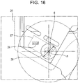
- FIG. 15 is a diagram illustrating the range of the board fastening point.
- FIG. 16 is an enlarged diagram of region D in FIG. 15 , which is a diagram for explaining the range of the disposition position of the thermistor.
- O is the center of minus terminal 3 (or clamp part 11), and a is the radius of minus terminal 3.
- b is the thickness of the electrode of clamp part 11
- c is the width (an example of the clearance distance) of the clearance between the side surface of clamp part 11 and resin mold 31.
- d is the larger of the bearing surface diameter of screw 30 or the diameter (the length of a diagonal line) of the contact portion between board 23 and attachment part 12.
- e is the distance from center O to the board fastening point (for example, the center of screw 30).
- the values a to c described above are values which are determined based on requirements of manufacturability of battery 1 and terminal 10 (clamp part 11 and attachment part 12).
- the value d described above is a value which is arbitrarily changed based on the demand for accuracy in the measurement of the temperature.
- distance e from center O to the board fastening point is larger than a + b + c, and smaller than a + b + c + d.
- distance e to the board fastening point is a condition under which favorable characteristics may be obtained where distance e being larger than a + b + c, and smaller than a + b + c + 3d is a realistic range in consideration of component variation. Therefore, it is desirable for distance e to be defined by the following expression (1). a + b + c ⁇ e ⁇ a + b + c + 3 d
- First circle c1 is a circle centered on point O and having the shortest distance (a + b + c) from point O to resin mold 31 as a radius.
- Second circle c2 is a circle with a distance (a + b + c + 3d) obtained by adding a length three times the maximum bearing surface width of screw 30 to the shortest distance a + b + c, or by adding a length three times the maximum width of the contact surface between board 23 and joint portion 20 to the shortest distance a + b + c as a radius.
- thermoistor 24 is disposed in the range of a circle with radius 3d which is centered on point P (the center of screw 30) on the first surface of board 23. It is desirable that thermistor 24 is disposed in a position in this range at which thermistor 24 is less susceptible to the influence of the heat of shunt resistance 17.
- thermistor 24 is disposed on board 23 and is provided close to the fastening point between board 23 and terminal 10 (attachment part 12). Accordingly, battery sensor device 100 of the present exemplary embodiment may be easily assembled without using a lead wire, an elastic member, or the like, and may accurately detect the temperature of battery 1.
- thermal conduction pattern 27 is formed on board 23; however, thermal conduction pattern 27 may not be formed on board 23.
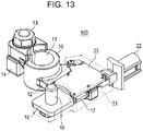
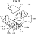
- FIG. 17 is a perspective diagram illustrating the configuration of battery sensor device 200 according to exemplary embodiment 2 of the present invention.
- FIG. 17 illustrates the configuration of battery sensor device 200 before being covered by resin mold 231.
- bus bar 215 is attached to terminal 210 (attachment part 212) in the same manner as in exemplary embodiment 1, and board 223 is provided on bus bar 215 in an overlapping manner.
- bus bar 215 includes cutout portion 215a.
- Projection portion 212a (a portion of attachment part 212) which has a thickness in the height direction is formed on terminal 210, and when bus bar 215 is attached to terminal 210, projection portion 212a is present in a location corresponding to cutout portion 215a.
- Board 223 includes protruding part 223a which protrudes from bus bar 215 toward the direction in which clamp part 211 is present, and when board 223 is caused to overlap bus bar 215, protruding part 223a is present on projection portion 212a (cutout portion 215a).
- Thermistor 224 (temperature sensor) is installed on the bottom surface (the surface facing the bus bar) of protruding part 223a (refer to FIG. 23 ).
- resin mold 31 (an example of the sealer) is formed so as to cover board 223 after board 223 is fastened to attachment part 212 by screw 30.
- resin mold 231 (an example of the sealer) is formed before board 223 is attached.
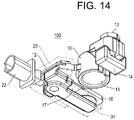
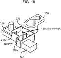
- FIG. 18 is a perspective diagram illustrating the configuration of battery sensor device 200 after resin mold 231 is formed.
- Resin mold 231 is formed so as to cover bus bar 215 and is molded integrally with connector portion 222.
- Resin mold 231 is formed in a case shape, the top surface being opened on bus bar 215.
- bus bar 216 is equivalent to bus bar 16 which is described earlier, description thereof will be omitted.
- hole portion 231a (refer to FIG. 19 ) is formed in resin mold 231 such that only the top surface of projection portion 212a (cutout portion 215a of bus bar 215) is opened.
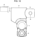
- FIG. 19 is a top surface diagram illustrating the configuration of battery sensor device 200 after resin mold 231 is formed.
- hole portion 231a is formed by resin mold 231, and projection portion 212a is visible through hole portion 231a.
- concave portion 250 with projection portion 212a as the bottom surface and resin mold 231 as the side walls is formed in a location corresponding to hole portion 231a (refer to FIG. 22 ).
- Recess portion 250 which is formed is filled with a thermal grease (heat transfer member), and board 223 is caused to overlap the bus bar so as to be connected to current detection terminals 218a, 218b, and 218c.
- a thermal grease heat transfer member
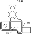
- FIG. 20 is a top surface diagram illustrating the configuration of battery sensor device 200 after board 223 is caused to overlap.
- board 223 is provided with protruding part 223a which corresponds to projection portion 212a (that is, cutout portion 215a and hole portion 231a).
- projection portion 212a (that is, cutout portion 215a and hole portion 231a) is covered by board 223 and may not be visually recognized.
- recess portion 250 which is formed by projection portion 212a and resin mold 231.
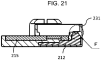
- FIG. 21 is a sectional diagram taken along the E-E line of FIG. 19 (after molding, before board overlapping), and FIG. 22 is an enlarged diagram of region F in FIG. 21 .
- FIG. 22 it is understood that by forming hole portion 231a, recess portion 250 (indicated by a dotted line) with projection portion 212a as the bottom surface and resin mold 231 as the side walls is formed.
- Recess portion 250 is filled with the thermal grease (heat transfer member), and board 223 is subsequently caused to overlap.
- FIG. 23 is a diagram illustrating a state after the thermal grease (heat transfer member) is filled, and board 223 is caused to overlap in FIG. 22 .
- thermistor 224 which is provided on the bottom surface of protruding part 223a of board 223 sinks into the thermal grease with which recess portion 250 is filled.
- thermistor 224 is capable of accurately measuring the temperature via projection portion 212a and the thermal grease.
- thermoistor 224 Since thermistor 224 is not directly attached to terminal 210 but via the heat transfer member (thermal grease), there is a margin in the alignment of thermistor 224, and the ease of assembly is improved.
- the opening portion of resin mold 231 is covered by a lid or the like which is formed of resin, for example, such that the resin is molded.
- the thermal grease heat transfer member
- the thermal grease is caused to fill recess portion 250 which is formed by projection portion 212a of terminal 210 (attachment part 212) and resin mold 231, and thermistor 224 which is provided on board 223 sinks into the thermal grease. Accordingly, battery sensor device 200 of the present exemplary embodiment may be easily assembled, and may accurately detect the temperature of battery 1.
- a battery sensor device may be applied to a battery or the like which is mounted on a vehicle, for example.
Landscapes
- Physics & Mathematics (AREA)
- General Physics & Mathematics (AREA)
- Chemical Kinetics & Catalysis (AREA)
- Engineering & Computer Science (AREA)
- Electrochemistry (AREA)
- General Chemical & Material Sciences (AREA)
- Chemical & Material Sciences (AREA)
- Manufacturing & Machinery (AREA)
- Nonlinear Science (AREA)
- Secondary Cells (AREA)
- Connection Of Batteries Or Terminals (AREA)
- Battery Mounting, Suspending (AREA)
- Measuring Temperature Or Quantity Of Heat (AREA)
- Measuring Instrument Details And Bridges, And Automatic Balancing Devices (AREA)
Applications Claiming Priority (2)
| Application Number | Priority Date | Filing Date | Title |
|---|---|---|---|
| JP2014187623 | 2014-09-16 | ||
| PCT/JP2015/004540 WO2016042732A1 (ja) | 2014-09-16 | 2015-09-08 | バッテリセンサ装置 |
Publications (2)
| Publication Number | Publication Date |
|---|---|
| EP3196972A1 true EP3196972A1 (de) | 2017-07-26 |
| EP3196972A4 EP3196972A4 (de) | 2017-09-06 |
Family
ID=55532790
Family Applications (1)
| Application Number | Title | Priority Date | Filing Date |
|---|---|---|---|
| EP15841571.1A Withdrawn EP3196972A4 (de) | 2014-09-16 | 2015-09-08 | Batteriesensorenvorrichtung |
Country Status (5)
| Country | Link |
|---|---|
| US (1) | US20170199084A1 (de) |
| EP (1) | EP3196972A4 (de) |
| JP (1) | JPWO2016042732A1 (de) |
| CN (1) | CN106575802A (de) |
| WO (1) | WO2016042732A1 (de) |
Families Citing this family (12)
| Publication number | Priority date | Publication date | Assignee | Title |
|---|---|---|---|---|
| JP6910762B2 (ja) * | 2016-06-27 | 2021-07-28 | Koa株式会社 | 電流測定装置 |
| FR3053794B1 (fr) * | 2016-07-11 | 2019-12-20 | Renault S.A.S. | Dispositif de mesure d'un courant a serrage vertical sur une borne de batterie |
| KR102287317B1 (ko) * | 2017-06-07 | 2021-08-10 | 현대자동차주식회사 | 전류센서 |
| JP6909406B2 (ja) * | 2017-12-05 | 2021-07-28 | トヨタ自動車株式会社 | 電池モジュール |
| JP2019169396A (ja) * | 2018-03-23 | 2019-10-03 | ダイハツ工業株式会社 | バッテリの温度推定装置 |
| WO2019236833A1 (en) * | 2018-06-06 | 2019-12-12 | Black & Decker, Inc. | Battery pack |
| JP2021083482A (ja) * | 2019-11-25 | 2021-06-03 | 株式会社村田製作所 | 口腔内測定装置及び口腔内測定システム |
| DE102020003458A1 (de) * | 2020-06-09 | 2021-12-09 | Wieland-Werke Aktiengesellschaft | Verfahren zur Herstellung einer Vorrichtung zur Messung von Stromstärken und Vorrichtung zur Messung von Stromstärken |
| JP2022001843A (ja) * | 2020-06-22 | 2022-01-06 | 矢崎総業株式会社 | 電流センサ |
| CN112067154A (zh) * | 2020-09-28 | 2020-12-11 | 珠海市科宏电子科技有限公司 | 一种蓄电池接线柱在线温度监测装置 |
| JP2022079017A (ja) * | 2020-11-16 | 2022-05-26 | 矢崎総業株式会社 | 導電モジュール |
| WO2024055476A1 (zh) * | 2022-09-15 | 2024-03-21 | 湖北亿纬动力有限公司 | 温度传感器及电芯组件 |
Family Cites Families (6)
| Publication number | Priority date | Publication date | Assignee | Title |
|---|---|---|---|---|
| DE19961311A1 (de) * | 1999-12-18 | 2001-07-26 | Bayerische Motoren Werke Ag | Batteriesensorvorrichtung |
| JP2009177903A (ja) * | 2008-01-23 | 2009-08-06 | Denso Corp | 車両システム |
| DE102008060668A1 (de) * | 2008-12-08 | 2010-06-10 | Auto-Kabel Managementgesellschaft Mbh | Batteriemessklemme |
| JP5630691B2 (ja) * | 2010-01-29 | 2014-11-26 | 株式会社デンソー | 電流検出装置 |
| JP5873626B2 (ja) * | 2010-10-06 | 2016-03-01 | 矢崎総業株式会社 | バスバー温度を正確に測定できる電流検出装置 |
| JP5926495B2 (ja) * | 2011-04-05 | 2016-05-25 | 矢崎総業株式会社 | シャント抵抗式電流センサ |
-
2015
- 2015-09-08 WO PCT/JP2015/004540 patent/WO2016042732A1/ja not_active Ceased
- 2015-09-08 US US15/327,373 patent/US20170199084A1/en not_active Abandoned
- 2015-09-08 CN CN201580041037.1A patent/CN106575802A/zh active Pending
- 2015-09-08 JP JP2016548551A patent/JPWO2016042732A1/ja active Pending
- 2015-09-08 EP EP15841571.1A patent/EP3196972A4/de not_active Withdrawn
Also Published As
| Publication number | Publication date |
|---|---|
| US20170199084A1 (en) | 2017-07-13 |
| WO2016042732A1 (ja) | 2016-03-24 |
| JPWO2016042732A1 (ja) | 2017-06-29 |
| CN106575802A (zh) | 2017-04-19 |
| EP3196972A4 (de) | 2017-09-06 |
Similar Documents
| Publication | Publication Date | Title |
|---|---|---|
| EP3196972A1 (de) | Batteriesensorenvorrichtung | |
| US9285401B2 (en) | Current detecting device and attaching structure thereof | |
| JP6452446B2 (ja) | バッテリー状態検知装置 | |
| US20150369877A1 (en) | Integrally formed current sensor device | |
| EP2793034A1 (de) | Auf einem shunt-widerstand basierender stromsensor | |
| US20090039880A1 (en) | Electric current detector having detector element holder coupled to magnetic core casing | |
| EP3300143B1 (de) | Vorrichtung zur erfassung eines batteriestatus und herstellungsverfahren dafür | |
| KR102190620B1 (ko) | 배터리 상태 검지 장치 및, 그의 제조 방법 | |
| US20150108965A1 (en) | Shunt resistance type current sensor | |
| JP6268128B2 (ja) | スイッチボックス及び過電流防止方法 | |
| JP5320960B2 (ja) | ケースモールド型コンデンサ | |
| JP5435442B2 (ja) | バッテリ状態検知センサ装置 | |
| JP5709056B2 (ja) | 電流検出装置 | |
| EP2899550A1 (de) | Stromsensor mit shuntwiderstand | |
| JP2015109236A (ja) | バッテリセンサ装置 | |
| JP5435928B2 (ja) | バスバ装置及びバッテリ液温推定装置 | |
| WO2015186421A1 (ja) | バッテリ状態測定装置及びそれを備えたバッテリ | |
| JP2018159613A (ja) | 温度検出装置 | |
| JP6925871B2 (ja) | 電流センサ付きバッテリーターミナル | |
| JP5762856B2 (ja) | 電流センサ | |
| KR200471707Y1 (ko) | 배터리 전류 검출 장치 | |
| JP2020030154A (ja) | シャント式電流センサおよびシャント抵抗付きバスバー | |
| JP2021135140A (ja) | 電流計測装置 | |
| JP2013224835A (ja) | シャント抵抗式電流センサ及びシャント抵抗式電流センサの製造方法 | |
| JP2013008846A (ja) | センサ |
Legal Events
| Date | Code | Title | Description |
|---|---|---|---|
| PUAI | Public reference made under article 153(3) epc to a published international application that has entered the european phase |
Free format text: ORIGINAL CODE: 0009012 |
|
| 17P | Request for examination filed |
Effective date: 20170117 |
|
| AK | Designated contracting states |
Kind code of ref document: A1 Designated state(s): AL AT BE BG CH CY CZ DE DK EE ES FI FR GB GR HR HU IE IS IT LI LT LU LV MC MK MT NL NO PL PT RO RS SE SI SK SM TR |
|
| AX | Request for extension of the european patent |
Extension state: BA ME |
|
| A4 | Supplementary search report drawn up and despatched |
Effective date: 20170804 |
|
| RIC1 | Information provided on ipc code assigned before grant |
Ipc: G01K 1/14 20060101ALI20170731BHEP Ipc: G01R 31/36 20060101ALI20170731BHEP Ipc: G01R 15/14 20060101ALI20170731BHEP Ipc: H01M 10/48 20060101AFI20170731BHEP |
|
| DAV | Request for validation of the european patent (deleted) | ||
| DAX | Request for extension of the european patent (deleted) | ||
| STAA | Information on the status of an ep patent application or granted ep patent |
Free format text: STATUS: THE APPLICATION IS DEEMED TO BE WITHDRAWN |
|
| 18D | Application deemed to be withdrawn |
Effective date: 20180302 |