EP3195434B1 - Leitungsführungseinrichtung, insbesondere für reinraumanwendungen, schalenteile und stützgerippe hierfür - Google Patents
Leitungsführungseinrichtung, insbesondere für reinraumanwendungen, schalenteile und stützgerippe hierfür Download PDFInfo
- Publication number
- EP3195434B1 EP3195434B1 EP15763941.0A EP15763941A EP3195434B1 EP 3195434 B1 EP3195434 B1 EP 3195434B1 EP 15763941 A EP15763941 A EP 15763941A EP 3195434 B1 EP3195434 B1 EP 3195434B1
- Authority
- EP
- European Patent Office
- Prior art keywords
- sheath
- guide device
- longitudinal
- line guide
- set forth
- Prior art date
- Legal status (The legal status is an assumption and is not a legal conclusion. Google has not performed a legal analysis and makes no representation as to the accuracy of the status listed.)
- Active
Links
Images


Classifications
-
- F—MECHANICAL ENGINEERING; LIGHTING; HEATING; WEAPONS; BLASTING
- F16—ENGINEERING ELEMENTS AND UNITS; GENERAL MEASURES FOR PRODUCING AND MAINTAINING EFFECTIVE FUNCTIONING OF MACHINES OR INSTALLATIONS; THERMAL INSULATION IN GENERAL
- F16L—PIPES; JOINTS OR FITTINGS FOR PIPES; SUPPORTS FOR PIPES, CABLES OR PROTECTIVE TUBING; MEANS FOR THERMAL INSULATION IN GENERAL
- F16L3/00—Supports for pipes, cables or protective tubing, e.g. hangers, holders, clamps, cleats, clips, brackets
- F16L3/01—Supports for pipes, cables or protective tubing, e.g. hangers, holders, clamps, cleats, clips, brackets for supporting or guiding the pipes, cables or protective tubing, between relatively movable points, e.g. movable channels
- F16L3/015—Supports for pipes, cables or protective tubing, e.g. hangers, holders, clamps, cleats, clips, brackets for supporting or guiding the pipes, cables or protective tubing, between relatively movable points, e.g. movable channels using articulated- or supple-guiding elements
-
- H—ELECTRICITY
- H02—GENERATION; CONVERSION OR DISTRIBUTION OF ELECTRIC POWER
- H02G—INSTALLATION OF ELECTRIC CABLES OR LINES, OR OF COMBINED OPTICAL AND ELECTRIC CABLES OR LINES
- H02G11/00—Arrangements of electric cables or lines between relatively-movable parts
- H02G11/006—Arrangements of electric cables or lines between relatively-movable parts using extensible carrier for the cable, e.g. self-coiling spring
-
- F—MECHANICAL ENGINEERING; LIGHTING; HEATING; WEAPONS; BLASTING
- F16—ENGINEERING ELEMENTS AND UNITS; GENERAL MEASURES FOR PRODUCING AND MAINTAINING EFFECTIVE FUNCTIONING OF MACHINES OR INSTALLATIONS; THERMAL INSULATION IN GENERAL
- F16G—BELTS, CABLES, OR ROPES, PREDOMINANTLY USED FOR DRIVING PURPOSES; CHAINS; FITTINGS PREDOMINANTLY USED THEREFOR
- F16G13/00—Chains
- F16G13/12—Hauling- or hoisting-chains so called ornamental chains
- F16G13/16—Hauling- or hoisting-chains so called ornamental chains with arrangements for holding electric cables, hoses, or the like
Definitions
- the invention relates to a line routing device for lines such as cables, hoses or the like, which has a first end for attachment to a fixed connection point and a second end for attachment to a further connection point which is relatively movable thereto.
- the line guide device forms an upper run, a movable deflection bend and a lower run between its ends.
- the deflection curve is curved or pivoted about a deflection axis, preferably with a predetermined radius of curvature, and can typically be moved in the plane perpendicular to the deflection axis.
- abrasion usually unavoidably occurs over time, i.e. small particles arise due to friction between the lines and / or the components of the line routing device.
- the invention relates in particular to a line guide device for those applications in which abrasion should not be released. This is the case, for example, in a clean room application.
- a generic line routing device which has a flexible sheath in the manner of a corrugated hose.
- This corrugated envelope (Engl. Envelope) surrounds the interior of the line routing device dust-tight, both in the longitudinal direction between the two ends, as well as in the circumferential direction.
- the dust-tight casing prevents the undesired escape of abrasion particles in a simple but effective way.
- a major advantage of the solution according to DE202013101203U1 lies in the fact that the sheath can be retrofitted as cable routing known per se, ie no complex special constructions are necessary to protect the cables.
- cable protection hoses as a generic line routing device. These are usually used when the mechanical stress on the cable routing device is relatively low.
- the laid-open specification describes DE 10 2012 000 798 A1 such a cable protection hose with an approximately rectangular cross-section, with an additional device for dividing the interior space into several hose areas for the various lines.
- This device has an elongated, flexible carrier and separating ribs projecting radially therefrom.
- engagement elements on the separating ribs engage from the inside in corrugated troughs of the protective tube and thereby prevent kinking.
- Disadvantageous in the solution DE102012000798A1 is first of all the effort required for the production. On the other hand, with this solution, large unsupported lengths, for example of the upper run, can possibly be realized with additional aids.
- the line routing device mentioned at the beginning DE202013101203U1 therefore forms a starting point for the present inventions.
- EP 1 291 996 A1 a line routing device according to the preamble of claim 1. It is a corrugated hose-like one-piece sheath, which is equipped with a variety of two-part attachments that form stops to achieve an asymmetrical bending behavior, namely in relation to the desired curvature around the deflection axis and the basically undesirable, opposite curvature.
- the preparation of the solution according to EP 1 291 996 A1 requires a considerable amount of work, partly due to the large number of individual parts.
- a first object of the invention is therefore to propose a line routing device which offers good protection against undesired escape of abrasion-related particles and which can be manufactured with less effort compared to the prior art.
- the cover is designed in the manner of a corrugated hose and has a corrugated profile, which at least supports the flexibility, and that the dust-tight cover has an asymmetrical bending behavior in relation to the desired curvature around the deflection axis and on the fundamentally undesirable, opposite curvature.
- the asymmetry is such that the permitted deflection of a self-supporting area is considerably less compared to the desired curvature, ie the curvature in the deflection curve.
- This asymmetry can be inherent in the envelope or can be achieved or reinforced by additional means, in particular add-on parts.
- the desired curvature around the deflection axis or inward curvature is referred to here as a “concave” curvature, and the undesired, opposite curvature or outward curvature is called a “convex” curvature.
- An asymmetrical bending behavior can in particular be achieved in that the casing has a lower, in particular axial compressibility radially on the outside or on the outside of its circumference - in relation to the deflection axis - than on the radially inside or on the inside of its circumference, ie that the outside in particular is compressible in the longitudinal direction of the envelope to a lesser extent.
- the corrugated tube-like shape of the cover can in principle be of any type, provided that it ensures the necessary flexibility.
- the envelope typically has wave crests and wave troughs or indentations and bulges, i.e. a corrugated profile, viewed in longitudinal section.
- a corrugated profile viewed in longitudinal section.
- a large number of different profiles are possible here, for example a curved profile, e.g. an approximately sinusoidal profile, an angular profile, e.g. a rectangular profile, a mixed shape with rounded edges, etc. about rectangular cross-sections, etc. into consideration.
- the bending behavior at least in the plane in which the upper run, lower run and deflection curve run, ie the plane in which the deflection curve can be moved an asymmetrical bending behavior, in particular a flexibility that varies depending on the bending direction , having.
- the flexibility is dependent in a predetermined manner on the direction of rotation of the bending moment, given the same strong bending moment.
- the envelope itself ie even without the use of a conventional energy guiding chain or special support chain, has a sufficient support function in the self-supporting area guaranteed.
- the casing itself can guide and support the lines. Accordingly, a support chain or typical energy chain can be completely dispensed with.
- the covering which is initially provided for sealing against dust, also takes on the essential functions of conventional energy routing chains.
- the covering in itself can be designed to limit the radius of curvature in the deflection curve on the one hand, but also to avoid excessive deflection in the upper run and / or in the lower run.
- the envelope itself can, if necessary with add-on parts, ensure a different minimum radius of the curvature or bend for both cases.
- the covering is therefore preferably not only self-supporting, but also designed as a support for the lines. Lines can therefore be guided directly in the casing without an additional device for receiving the lines.
- all information on the effects and design of the cover in particular the shape and dimensions, relate to the state of rest or the stress-free state of the cover.
- the deflection refers, unless otherwise stated, to the bending in the extended position with a nominal line load, but without any other load or without overload.
- dust-tight does not necessarily mean hermetically gas-tight or closed in such a way that nothing can penetrate or escape. Rather, dust-tight means technically tight against the escape of abrasion particles of typical grain sizes, which in conventional energy chains are caused by friction between the chain links or the cables.
- the application of the invention is not restricted to clean room applications. Because of the inherent flexibility, articulations with friction can be avoided. Due to the asymmetrical flexibility and the associated lower deflection, the cover is suitable at least for short unsupported lengths.
- Asymmetrical bending behavior is present in the context of the invention at least over a longitudinal section of the line routing device.
- the flexibility can optionally also be differently asymmetrical and / or symmetrical in sections.
- flexibility that varies over the length is also within the scope of the invention.
- a course essentially lying in one plane is implemented in each of the individual sections, with planes also being able to differ in sections and, for example, being perpendicular to one another.
- the corrugated hose-like sheath allows only a very slight or essentially no convex curvature, ie only very little or essentially no deflection, even when completely filled with lines - compared to the desired concave curvature. In this way, an optimal, approximately straight course of the upper run can be guaranteed.
- the casing In the unloaded state, the casing can have a slight concave pre-curvature or prestress for this purpose.
- An asymmetrical, direction-dependent bending behavior can be achieved, for example, by making the cover from at least two different materials, in particular plastics with different flexibility. A suitable material distribution over the cross-section can already ensure the desired behavior.
- the asymmetrical bending behavior is achieved at least predominantly or exclusively in that the corrugated hose-like casing has a different corrugated profile on the outside of its circumference than on the inside of its circumference.
- the desired curvature behavior of the envelope itself can be predefined or specified by different types of profile design on the two sides. Accordingly, no additional components, such as support or guide chains, are required for this.
- the different types of profiles on the two sides of the envelope can, in addition to the direction-dependent flexibility, also in particular predetermine a plane of swiveling or curvature of the envelope.
- the profile design, in particular on the outside can be selected so that one of the two corrugated profiles has higher shear and compressive strength than the other profile.
- the different profiles can be made of the same or different material.
- the corrugated hose-like casing on the outside has a profile with wave troughs whose clear axial width is less than 20%, in particular less than 10%, of the axial width of the wave crests. So there is only very little free space available for upsetting on the outside. A compression of the wave crests themselves can in turn be reduced or prevented by their design.
- the corrugated profile on the outside or radially outside has an omega shape in longitudinal section.
- wave crests have flanks that are bulged towards the ends.
- the profile is designed in such a way that these flanks are in abutment with one another on both sides in the extended position of the casing, in particular in the cantilevered upper run.
- the corrugated hose-like casing has a corrugated profile on its inside with wave troughs, the clear axial width of which is at least 50% of the axial width of the wave crests, and in particular is approximately the same size.
- a tried and tested profile known per se can be provided on the inside.
- Different types of profiles on the two sides of the cover can be realized in particular in plastic, by suitable methods of plastics technology, even with coverings that are one-piece in sections or over the entire length.
- One-piece covers are inherently dust-tight.
- a more easily variable and simple production of the corrugated tube-like casing in terms of the radius of curvature is made possible if it is composed in sections in a modular construction, each from two shell parts with different profiles.
- inside shell parts with different predetermined radii of curvature can be combined with an outside shell part that avoids bending.
- the interface at which the two shell parts are connected is preferably at the level of the neutral fiber of the line routing device, where a dust-tight connection of the parts is simplified by minimal relative movement.
- a structure of the envelope with sections from two shell parts also enables at least one shell part, preferably the shell part on the outside, to have one or more integrally formed separating webs which divide the interior space in cross section. Through the division In a respective channel area for each line, abrasion due to friction between the lines is minimized or avoided.
- the line routing device is particularly light, runs with little noise and vibration, requires little maintenance and can be manufactured relatively inexpensively. Accordingly, it can be used in a wide variety of applications.
- the first aspect also relates to the shell part for producing a line routing device according to one of the above-mentioned embodiments.
- the shell part for this purpose can be made in one piece from flexible plastic and, in longitudinal section, have a corrugated profile with asymmetrical bending behavior in relation to a curvature about a deflection axis and an opposite bend.
- the corrugated profile is selected in the sense of the invention in such a way that the permitted curvature is considerably less than the desired curvature.
- an externally attached, separate supporting skeleton with circumferential transverse ribs can be used as an alternative or in addition to the first aspect to determine the curvature behavior or to achieve or reinforce asymmetrical flexibility are provided.
- the sheath can be designed in particular as a conventional corrugated hose with inherently symmetrical or direction-independent bending behavior. Together with the supporting structure as an attachment, the corrugated hose with conventional profiling then forms the envelope.
- the casing has a separate support structure attached from the outside with transverse ribs running in the circumferential direction, which comprise projections protruding in the longitudinal direction on an outer side as stops to prevent deflection.
- the projections are designed in such a way that, due to the projections, the transverse ribs are in abutment with one another in an extended or cantilevered position of the casing.
- the projections of adjacent transverse ribs can work together, in particular work together in a centering manner, in order to increase the length and also the lateral stability of the self-supporting part, in particular the upper run.
- This solution has the advantage that it is compatible with conventional corrugated tubing of various diameters within a nominal range.
- the supporting structure has flexible holding arms protruding in the circumferential direction on both sides. These make it possible to hold the support structure on the outside of the envelope, similar to clamps or open clamps.
- the transverse ribs can engage from the outside or on the outside into the corrugated profile of the corrugated tube-like casing.
- the transverse ribs engaging over half the circumference together with the wave crests together form a stiffening against bending, since the wave troughs are occupied.
- the supporting framework for achieving asymmetrical flexibility can also be attached in the interior, i.e. with transverse ribs which engage in the corrugated profile from the inside or on the inside.
- the arrangement on the inside is more complex, but also inherently avoids theoretically possible abrasion between the support structure and the casing.
- the clear axial width or the free space between wave crests and / or wave troughs on the outside can be compared in a simple manner with the corresponding free space between wave crests and / or wave troughs on the inside can be reduced.
- the plane of curvature and / or the radius of curvature can also be specified by the design of the supporting structure.
- the supporting structure is preferably designed in such a way that a corresponding transverse rib engages in at least every third wave of the corrugated profile, preferably in every wave of the corrugated profile. In this way, the axial compressibility of the outside is considerably reduced.
- the support structure has two opposing ones and has supports running in the longitudinal direction which carry the transverse ribs, the supports preferably lying at the level of the neutral fiber of the line routing device or providing this, for example in the case of a conventional corrugated hose as a sheathing.
- the support frame is preferably made in one piece, in particular as an injection-molded part made of plastic.
- Corresponding carriers can be attached to the connection points at both ends in order to absorb tensile and compressive forces when moving the deflection arch and thus relieve the actual envelope.
- the support structure has a longitudinal extension which corresponds at least to the maximum length of the upper run, preferably the total length of the line guide device. Lateral stability against bending out of the plane of curvature can be achieved by the supporting framework, in particular the carrier.
- the carriers have lateral fastening means for connection to the support structure of a further casing. In this way, several sheaths can be attached to one another in parallel in order to form a line routing device with a larger receiving space.
- fastening means at the end can be provided on the girders for fastening support frames following one another in the longitudinal direction and, if necessary, for transmitting tensile and shear forces.
- the support structure for example as an extension of the transverse ribs transversely to the girders, has approximately wedge-shaped or V-shaped, relatively short extensions, tabs or tongues on both sides, which over a small circumference in engage the corrugated profile on the inside in order to specify a minimum radius of curvature of the deflection curve through the included angle of the wedge or V-shape.
- a lower compressibility in particular in the axial or longitudinal direction, is realized in cross section over a portion of the outer circumferential area which is at least 12.5%, preferably between 25% and 50% of the full circumferential dimension of the envelope amounts to.
- a suitable profile or support structure should therefore effectively reduce the compressibility on the outside over a certain angular or circumferential dimension of the cross section.
- the corrugated profile of the Sheath is corrugated in a parallel ring shape, ie is not corrugated in a helical or helical manner.
- the sheath and, if appropriate, also the supporting structure are expediently made from a flexible plastic, in particular from an elastic and permanently flexurable plastic, preferably a thermoplastic.
- the proposed concept makes it possible, in particular, to limit the static convex deflection to a radius which is many times, in particular at least 10 times, greater than the static bending radius of the corrugated tube-like casing in the case of a concave curvature.
- the static bending radius is understood here to be the minimum radius in the resting state (without movement) at which the limit of plastic deformation is reached.
- a module for the modular construction of a support frame or a support frame module is also described as relevant for the second aspect. It is used together with a sheath comprising a corrugated hose with a corrugated profile for producing a line routing device for lines, in particular according to the first and second embodiment of the second aspect.
- a support frame module is made in one piece from flexible plastic, has a longitudinal extension and is designed in such a way that it can be attached to a corrugated hose from the outside. It also has a plurality of transverse ribs running in a circumferential direction, i.e. transverse to the longitudinal extension.
- the module has transverse ribs that can at least partially engage in the corrugated profile of the corrugated hose, or transverse ribs that include projections protruding in the longitudinal direction such that the transverse ribs abut with one another in a stretched or cantilevered position, in the sense of the corresponding description above .
- the module can also have all or some of the aforementioned further features of the supporting framework, in particular carriers, lateral and / or end-side fastening means for expansion or modular extension, holding arms, etc.
- a supporting framework according to the second aspect is particularly advantageous for small radii in the deflection area, since a particularly flexible material of the cover is desirable here. The latter stands in the way of a slight deflection in the self-supporting area.
- a support frame can also be combined with a profile design according to the first aspect.
- Another aspect of the first group of the invention relates to the strength and sealing effect against dust particles of the connection for assembling the individual shell parts, in particular an improvement over the teaching from DE 20 2014 104 458 U1 can be achieved.
- a corrugated hose-like shell part for a line routing device which is formed by a corrugated hose-like sheath which is composed in sections of two shell parts, in particular two shell parts with different profiles.
- the shell parts can be connected longitudinally at the interface in various ways, e.g. after production, permanently using adhesive or welding technology, in particular a connection technology suitable for plastics such as ultrasonic welding.
- a non-destructive detachable and yet sufficiently strong connection is preferred, however, in particular in order to enable the envelope to be opened later.
- the shell part has a longitudinally extending, in particular continuous fastening strap on both longitudinal sides, which has a toothing, preferably with regularly arranged staples (Engl. Teeth) or teeth that are connected to a corresponding toothing on an opposite shell part in the manner of a zipper (Engl. zip fastener) cooperate.
- a toothing preferably with regularly arranged staples (Engl. Teeth) or teeth that are connected to a corresponding toothing on an opposite shell part in the manner of a zipper (Engl. zip fastener) cooperate.
- This ensures a good connection between the opposing shell parts that is firmly closed during operation.
- good lateral stability can be achieved through the fastening straps, but also an elongated cross-section and a transversely rigid design of the shell parts.
- the staples of the connector which acts like a zip fastener or zip fastener, can in particular have an effective cross section which at least approximately corresponds to the shape of an isosceles trapezoid.
- the effective cross section can, for example, be that of an isosceles trapezoid with rounded corners. It can be provided that a narrow side of a trapezoidal staple faces away from the shell part to be connected and that the tapering legs of the trapezoidal staples of two connected parts are wedged together.
- the wedge-shaped or trapezoidal design in particular allows the opposing shell parts to be fastened or opened approximately perpendicular to the longitudinal direction.
- the staples can in particular form projections laterally outward as an extension of the band, particularly in a direction perpendicular to the longitudinal direction of the shell part or the line guide device.
- the staples can each also protrude slightly from the fastening band in the direction of the other shell part.
- a shell part has a longitudinal groove which interacts in a form-fitting manner with a corresponding spring on the other shell part to be connected.
- the other shell part preferably in the area between the toothing and the transition to the corrugated hose-like casing, has a spring which interacts positively with a corresponding longitudinal groove on the shell part to be connected.
- This can also be provided for shell parts according to the first and possibly the second aspect.
- the sealing projection can be designed with an initially tapering cross-section that is thickened at the end and preferably resembles a mushroom head or a game stone.
- the joint between the fastening strips forms the neutral fiber of the line routing device.
- the fact that the layer ( neutral fiber), which maintains a constant dimension in the longitudinal direction when it is curved, lies exactly at the interface, enables, among other things, a firm attachment of the shell parts to one another, since gape is prevented when bent.
- each connection flange comprises two clamping shells which can be connected in a dust-tight manner and which hold the casing in a force-fitting and / or form-fitting manner at a front end region and surround it in a dust-tight manner.
- the connection flange preferably has fastening means for fastening, in particular for screw connection with the respective connection point.
- both clamping shells of each connection flange have such fastening means, so that they are secured to one another at the same time as they are fastened to the connection point.
- each connection flange has in one end area, preferably opposite the front end area, a suitable lead-through seal for the dust-tight lead-through of the lines.
- FIG.1 a schematically shown line routing device is generally designated 100.
- the line routing device 100 is used for the protected routing of cables, hoses or similar lines, which are not shown in detail in the figures.
- the line guide device 100 forms a deflection bend 104 with a predetermined curvature in a known manner.
- the deflection bend 104 has, in particular, a predetermined, minimum radius of curvature and thus ensures that the permissible radii of curvature of the guided lines are not undershot.
- the deflection bend 104 can be moved over a distance relative to the fixed connection 105 together with the movable connection 107.
- the movement takes place essentially in a plane, which here is approximately vertical, and follows the movement of the movable connection 107.
- the fixed connection 105 is located on the upper run 101 and the movable connection 107 is located on the lower run 103.
- the two ends of the line routing device 100 can also be connected the other way around.
- FIG.1 also shows schematically, as an essential aspect of the invention, a flexible casing 110 which surrounds the lines routed in the interior in the circumferential direction and between the two connections 105, 107 in a continuously closed and technically dust-tight manner.
- the sheath 110 is made hose-like and sufficiently flexible, for example through a suitable design and / or choice of material, in order to accommodate the fixed predetermined curvature of the deflection curve 104 and to follow the movement of the deflection curve 104 with as little resistance as possible.
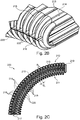
- FIG.2A-2B show a first exemplary embodiment of a line routing device 200 according to the invention with a sheath 210
- Sheath surrounds an interior space 208 in a dust-tight manner, so that abrasion particles cannot escape.
- the envelope 210 has asymmetrical bending behavior with regard to concave and convex curvature around the deflection axis (schematically with A in FIG.1 indicated).
- the casing 210 has on its inside 211 (ie the broad side radially inside) and its outside 212 (ie the broad side radially outside) corrugated hose-like but different types of profiles.
- the profile has on the outside 212 wave crests 214, the shape of which in longitudinal section ( FIG.2c ) is approximately ⁇ -shaped (omega-shaped), so that flanks 215 of the corrugation peaks 214 bulging at the ends can be in abutment with one another on both sides of the corrugation peaks 214 in the extended position of the casing 210.
- the envelope 210 in comparison to the desired concave curvature about the deflection axis A (cf. FIG.1 ) only allows slight or essentially no convex deflection in the other direction.
- the sheath 210 itself can ensure an approximately straight course of the upper strand, even if it is loaded with the weight of the guided lines (not shown).
- the wave troughs 216 between the wave crests 214 have a very small free or clear axial width B2, here for example less than 20% of the axial width of the wave crests 214 on the outside 212.
- the clear axial width B2 of the wave troughs 216 on the outside 212 is also significantly smaller than the corresponding clear axial width B1 of the wave troughs 218 on the inside 211.
- the corrugated tube-like casing 210 can have a conventional profile on the inside 211 in contrast to the outside 212, for example a rounded corrugated profile with wave troughs 218 and wave crests 220, the largest dimension thereof is approximately the same in the longitudinal direction or axial width.
- the line routing device 200 is made up of sections of the sheath 210, as in FIG.2A shown assembled.
- each section is made in one piece, in particular from plastic, in the longitudinal direction and in the circumferential direction.
- To connect two sections of the casing 210 they each have a completely encircling latching ring 219 at one end face.
- the locking ring 219 can be inserted into the opposite end 217 in the manner of a tongue and groove connection Engage positively.
- Each locking ring 219 is slightly oversized compared to the corresponding conjugate receptacle at the opposite end 217, so that a dust-tight press fit can be realized.
- flange-like longitudinal struts 222 are provided at the level of the neutral fiber of the line guide device 200 at the transition between inside 211 and outside 212.
- the longitudinal struts 222 are integrally connected to the material which forms two adjacent wave crests 214 on the outside 212 of the casing 210. In this way, together with the flanks 215 of the wave crests 214 acting as stops, a stable structure is made possible which also allows great unsupported lengths when the line guide device 200 is completely filled without disturbing deflection.
- the integrally produced sections such as FIG.2A shows, already be concave pre-curved in a load-free position, ie manufactured with an inherent preload in relation to the extended position.
- the longitudinal struts 222 also increase the shear and compressive strength, ie the mechanical load-bearing capacity of the sheath 210, so that a line routing device 200 with a great overall length can be implemented.
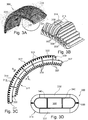
- FIG.3A-3C show a second embodiment of a line routing device 300, which also has a sheath 310 with asymmetrical bending behavior in relation to the curvature concave and convex around the deflection axis A.
- This is analogous to FIG.2A-2C a different profile is provided on the outside 312 than on the inside 311.
- Corresponding or identical features in comparison to FIG.2A-2C are accordingly provided with correspondingly increased reference numerals and are not described repeatedly.
- a major difference of the second embodiment according to FIG.3A-3D lies in the fact that the sections for assembling the sheath 310 in sections, unlike in FIG.2A-2C , are each composed of two separately produced shell parts 331, 332, one shell part 331 with a profile forming the inside 311 of the casing 310 and the other switch part 332 with a different profile forming the outside 312.
- the interface 335 for connecting the shell parts 331, 332 to one another is at the level of the neutral fiber of the line guide device 300.
- the connection can, as FIG.3B exemplarily illustrated by means of any form and / or non-positive connection can be realized.
- Both shell parts 331, 332 at the interface 335 each have snap fasteners 333 arranged alternately in the wave troughs 316 and 318 and correspondingly conjugate shaped receptacles 334.
- Other fastening means suitable for a dust-tight connection of the shell parts 331, 332 are also within the scope of the invention. If no material connection is used, the second embodiment facilitates after FIG.3A-3D compared to the first example in FIG.2A-2C maintenance, since individual longitudinal sections of the line guide device 300 are more easily accessible.
- the shell parts 331, 332 are preferably fastened to one another with a certain longitudinal offset relative to one another, similar to a brickwork course.
- the fastening means provided for connecting two opposing shell parts 331, 332 to one another for example snap fasteners 333 and corresponding recesses 334, can also be used to reinforce the longitudinal connection of the subsections of the casing 310 in the longitudinal direction.
- a connection of the shell parts 331, 332 that is shear-proof in the tensile direction is preferred at the interface 335.
- each shell part 331, 332 preferably has a type of sealing lip 339 at one end, which engages sealingly in the end-side wave crest 314 at the opposite end 317.
- FIG.3D shows a further difference between the second exemplary embodiment and FIG.2A-2C .
- separating webs running in the plane of movement can be arranged on one of the two shell parts 331, 332, for example on the shell part 332 forming the outer side 312, in order to divide the interior space 308 are routed separately, whereby abrasion between these lines is largely avoided.
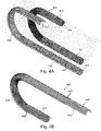
- FIGS. 4A-4C show an alternative, third embodiment of a line routing device 400.
- This consists, apart from connection flanges for the dust-tight fastening of the ends (as in FIG.8A-8B shown by way of example), consisting of only two essential components, namely a casing 410 and a specially manufactured support structure 440.
- the in FIG.4A Sheath 410 shown individually can be designed as a conventional corrugated hose. Accordingly, the corrugated hose 410 in and of themselves have a symmetrical bending behavior in every direction, i.e. also with regard to concave or convex curvature around the deflection axis of the deflection curve 104 ( FIG.1 ).
- the separately produced support frame 440 is attached from the outside, in relation to the deflection bend 104 on the outside 412 of the corrugated hose 410.
- the supporting structure 440 is asymmetrical in terms of its bending behavior. It can be bent slightly concave around the deflection axis A, but only to a limited extent convex in the opposite direction. How best to look FIG.4C As can be seen, the support structure 440 has two opposite supports 442 running in the longitudinal direction, on which essentially perpendicular transverse ribs 444 running in the circumferential direction are provided.
- the supports 442 and transverse ribs 444 can be produced in one piece from plastic, for example by injection molding.
- transverse ribs 444 are as in FIGS. 4A-4B approximately circular arc-shaped and have a radian dimension of about 180 ° (see also FIG.5 ).
- the transverse ribs 444 of the support structure 440 which run in the circumferential direction, are fastened to the supports 442 parallel to one another at a regular, predetermined distance.
- the transverse ribs 444 mainly serve to fill or close the otherwise free wave troughs 420 on the outside 412 of the corrugated hose 410 as far as possible.
- the support structure 440 is thus preferably designed in such a way that the regular spacing between the transverse ribs 444 corresponds to the wavelength, ie the periodic spacing between two successive wave troughs 420 of the corrugated hose 410. In this way it is achieved that exactly one transverse rib 444 engages in each wave of the corrugated profile.
- the support frame 440 In addition to the function of reinforcing the corrugated hose 410, the support frame 440 also has the effect of defining the neutral fiber at the level of the opposite carrier 442 and at the same time also the plane of movement of the deflection bend 104 ( FIG.1 ). Not closer Connection means are shown at the ends of the support frame 440 in order to firmly connect the carriers 442 to the connection points (cf. FIG.8 ).
- the support frame 440 can additionally absorb tensile and compressive forces through the carrier 442 and increase the service life and load-bearing capacity of the corrugated hose 410.
- the support frame 440 accordingly preferably has a longitudinal extension which corresponds to the total length of the line routing device 400 from one connection point to the other connection point 105, 107 ( FIG.1 ) corresponds.
- FIG.4C tab-like or tongue-like extensions 446 provided on both sides in a tangential extension of the transverse ribs 444.
- the extensions 446 are approximately wedge or V-shaped in a side view.
- the extensions 446 and 446 have a very short extent in the circumferential direction compared to the circumference of the corrugated hose 410 and form a predetermined opening angle between the end-side legs facing in the longitudinal direction.
- the extensions 446 grab how FIG.4B-4C show a small circumferential dimension on the outside into the wave troughs 420 of the corrugated hose 410.
- the minimum radius of curvature of the deflection bend 104 of the line routing device 400 made of corrugated hose 410 and support frame 440 is specified by a predetermined angular dimension of the opening angle between the opposite legs of the extensions 446.
- FIG.5 shows a development of the embodiment according to FIGS. 4A-4C .
- the line routing device 500 apart from the end connection flanges, essentially consists of three corrugated hoses 510 which are arranged laterally next to one another and in parallel and which are held in parallel by support frames 540.
- there are three support frames 540 identical in structure to FIGS. 4A-4C , each laterally attached to one another with their brackets 542.
- the support frames 540 are preferably produced as separate individual parts and have suitable connecting means on the supports 542 for connection to the adjacent support frame 540.
- a plurality of supporting frameworks 540 can also be made coherently from one piece.
- FIGS. 6A-6C shows, as a further embodiment of a line routing device 600, a modification of the example according to FIGS. 4A-4C .
- the line routing device 600 can also essentially consist of a conventional corrugated hose as a sheath 610, here with an approximately rectangular cross-section, and a separate support frame 640 to achieve asymmetrical bending behavior.
- the support frame 640 of the line guide device 600 is not arranged on the outside of the corrugated hose 610, but on the inside in the casing 610 designed as a corrugated hose.
- the support structure 640 has both transverse ribs 644 facing the outside 612 and transverse ribs 645 facing the inside 611.
- the outer transverse ribs 644 engage from the inside into the cavity of the wave crests 620 on the outside of the casing 610.
- the inner transverse ribs 645 engage from the inside correspondingly into the cavity of the wave crests 620 on the inside 611 of the casing 610.
- the corrugated tube-like casing 610 itself can attack Both sides have an identical, conventional corrugated profile with corrugation valleys 618 and corrugation peaks 620 of identical shape on both sides. In contrast to what is shown in the figures, the casing 610 can be produced continuously between the two ends.
- the support frame 640 can be produced continuously in one piece or assembled from individual sections which are inserted into the casing 610 one after the other.
- FIG.2A-2C As an alternative to a conventional corrugated hose with inherently symmetrical bending behavior, it is also conceivable, analogously to FIG.2A-2C or. FIG.3A-3D to assemble the casing 610 in sections from one- or two-part modules. In the latter case, the corrugated profile on the inside 611 can be designed differently than the corrugated profile on the outside 612.
- the asymmetrical bending behavior is mainly achieved with the support frame 640 in that the transverse ribs 644 on the outside 612 have a greater axial width than the transverse ribs 645 on the inside 611. In this way, as in the previous exemplary embodiments, it is ensured that the sheath 610 has a lower compressibility axially or in the longitudinal direction on its outer side 612 than on its inner side 611.
- the support frame 640 enables, on the one hand, reinforcement due to the differently shaped transverse ribs 644 and 645 on the inner and outer sides 611 and 612 of the sheath 610 against bending in the cantilevered upper or lower run 101 or 103 and, on the other hand, at the same time the limitation to a predetermined radius of curvature in the deflection curve 104.
- the transverse ribs 644 on the inside have a smaller axial width than the transverse ribs 645 on the outside.
- a defined neutral fiber for the bending path of the sheath 610 is given by opposite supports 642 to which the circumferential transverse ribs 644, 645 are attached.
- the carriers 642 can also be used for interception can be used by pushing and pulling forces with appropriate attachment to each other or at the connection points.
- the lines (not shown in more detail) are directly in the interior space 208; 308; 408 ... picked up and guided and carried by the cover.
- a special, additional line routing is shown in the examples below FIG.2-6 not mandatory.
- FIG.7A-7C show a line routing device 700 according to a principle that is different and independent from the preceding exemplary embodiments.
- the line routing device 700 consists essentially of a tape-like line guide 760, of individual sections 762 fastened to one another in the longitudinal direction, and a dust-proof one-part or multi-part cover 710.
- Each section 762 as a link of the line guide 760 has a left and a right side part 764, which over a continuous carrier tape 766 are integrally connected, or alternatively attached to the side as separate parts.
- the carrier tape 766 is flexible about the deflection axis and made of a flexible, tensile plastic. To improve the flexibility about the deflection axis, the carrier tape 766 is provided with a hole pattern, the elongated holes of which run transversely to the longitudinal direction.
- the dust-tight casing 710 is composed in a modular manner from longitudinal sections, each with two shell parts 731 and 732.
- the sections 762 of the line guide 760 each have fastening projections 768 protruding laterally from the side parts 764 outward.
- the fastening projections 768 have fastening means 769 following one another at regular intervals.
- the fastening projections 768 are used to fasten an inner and outer shell part 731 or 732 of a casing 710.
- FIG.7B shows as fastening means 769, for example, eyelets for fastening by means of a snap-in connection, such as by means of a snap fastener or the like.
- Other form-fitting and / or force-fitting fastening means 769 are also within the scope of the invention, for example a tongue / groove connection or other suitable plastic fasteners, e.g. patent US2613421A .
- the fastening protrusions 768 preferably form integral, planar extensions of the carrier tape 766.
- the fastening protrusions 768 and the carrier tape 766 are arranged at the level of the neutral fiber of the line routing device 700 or provide this.
- the plane of movement of the deflection curve 104 (cf. FIG.1 ) specified.
- the interface between the shell parts 731 and 732 is also at the level of the neutral fiber.
- Each side part 764 has a longitudinally extending connecting web 770 which is flexible about the deflection axis and which is optionally produced in one piece with the carrier tape 766 and which is used to transmit compressive and tensile forces.
- Another connecting web can be used for transverse stabilization, such as FIG.7C best shows, be provided centrally in the carrier tape 766.
- T-shaped webs 771 and 772 are integrally formed on each side part 764 towards the inside 711 and the outside 712.
- the T-shaped webs 771, 772 each have a foot web 773 and a longitudinal web 775 or 776 running in the longitudinal direction.
- the inner T-shaped webs 771 form first stops to limit the radius of curvature in the deflection curve 104 on the longitudinally facing end faces of their longitudinal webs 775
- the opposite, second T-shaped webs 772 form second stops for limiting the convex deflection in the opposite direction on the end faces of their longitudinal webs 776 pointing in the longitudinal direction.
- the structure, arrangement and mode of operation of the T-shaped webs 773, 776 correspond to the preferred exemplary embodiment of the T-shaped webs in the patent EP 2 142 823 B1 , the content of which is fully referred to in order to avoid unnecessary repetition.
- the line guide 760 differs from the ribbon chain-like line guide device according to FIG EP2142823B1 in particular by the fastening projections 768 for fastening the casing 710. Another difference lies in the one-piece production of the sections 762, ie the side parts 764 and carrier tape 766 are made from one piece. Otherwise, the structure and mode of operation can be derived from the preferred exemplary embodiment EP2142823B1 correspond, in particular with regard to the form-fitting connector 778 at the end on the side parts for chaining the sections 762 in the longitudinal direction.
- the casing 710 in the exemplary embodiment according to FIG.7A-7C can basically be designed as desired, provided it is closed dust-tight.
- the envelope 710 can, taken by itself, have an asymmetrical bending behavior with regard to concave and convex curvature around the Deflection axis A (cf. FIG.1 ) or, in this regard, a symmetrical bending behavior.
- the limitation of the radius of curvature in the deflection bend 104 is ensured in the line routing device 700 by the internal T-shaped webs 771 of the line routing 760.
- large unsupported lengths are ensured by the external T-shaped webs 772.
- the attachment of the shell parts 731, 732 of the sheath 710 to the line guide 760 can take place in any known manner suitable for a dust-tight connection, with detachable connections being preferred.
- FIG.7A-7C show a casing 710, which is composed in sections of two shell parts 731, 732 and secured to fastening projections 768 on both sides.
- a one-piece envelope which can be folded open or bent open in its circumference, can also be attached to one of the side parts 764 on only one side. For this purpose, it is therefore sufficient if fastening projections 768 are only provided on one side.
- FIG.8A-8B show a preferred embodiment of suitable connection flanges 880 for the end attachment of one of the above-described line routing devices to the connection points 105, 107 (cf. FIG.1 ).
- the casing 810 is shown as a corrugated tube or hose with parallel corrugation and an elongated or elongated cross-section, for example in FIG.2A-2C , FIG.3A-3D or FIG.7A-7C .
- FIG.8B shows in an exploded view only a part of the sheath 810 or the line routing device 800, namely one of the two similarly designed end regions, which are each fastened with an identically designed connection flange 880.
- the connection flanges 880 also serve to seal off the open ends of the casing 810 in a dust-tight manner and to fasten them to the connection points 105, 107.
- each connecting flange 880 is composed of two interacting clamping shells 881, 882, which are designed as cover-like injection-molded molded parts that can be connected in a dust-tight manner.
- the clamping shells 881, 882 can be latched to one another by snap hooks 883 and recesses 884, other form-fitting and / or force-fitting connections, in particular releasable latching connections, also being possible.
- the closed clamping shells 881, 882 hold on a front end region 885 in a non-positive and / or form-fitting manner, in particular positively by engaging in one or more wave troughs, the casing 810 is fixed in the longitudinal direction and the casing 810 is circumferentially dust-tight, possibly by means of an additional seal (not shown).
- FIG.8A-8B two pairs of through openings 887 for connecting screws 888 are provided on both clamping shells 881, 882 for fastening purposes.
- the through-openings 887 for connecting screws 888 in the rear end area 886 also allow a feed-through seal 890 to be fastened for the dust-tight feed-through of the cables and hoses.
- the feed-through seal 890 can be clamped onto the lines using the connecting screws 888, for example.
- the separate feed-through seal 890 in each connection flange 880 is preferably compressible and / or provided with cutouts for the lines.
- the feed-through seal 890 can, for example, be designed as a one-piece polyurethane block or as a multi-layer neoprene stack.
- an internal holder for the feed-through seal 890 In the rear end area of the clamping shells 881, 882 there is in each case an internal holder for the feed-through seal 890.
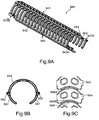
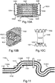
- FIGS.9A-9C show a longitudinal section of a further embodiment of a support structure 940, namely an elongated module 941 for joining in sections with further identical modules 941.
- a support structure 940 namely an elongated module 941 for joining in sections with further identical modules 941.
- clip connectors 943A, 943B conjugated to support strands 942 with locking clips and receptacles are provided around the modules 941 or support strands 942 chain together lengthways.
- the support structure 940 or module 941 is made in one piece or integrally from rigid plastic and has, among other things, a large number of transverse ribs 944.
- the transverse ribs 944 extend in cross-section in the shape of a circular arc over approximately half the circumference between the two longitudinally parallel support strands 942 and are in FIG arranged parallel to one another at regular longitudinal spacing. Also regularly parallel, each opposite in cross section ( FIG.9B ) a multiplicity of holding arms 947 arranged in mirror symmetry in pairs. The holding arms 947 also run essentially in the shape of a circular arc in cross section, each only over a portion of the circumference, for example over approximately one eighth of the circumference. The holding arms 947 can spread open in order to radially support the support structure 940 on a corrugated hose (not shown here, cf. 410 in FIG FIG.4A ) to be attached. The holding arms 947 can be in the longitudinal direction merge centrally between the transverse ribs 944 into the carrier strands 942.
- a support structure 940 made of modules 941 can be better than the support structure in FIGS. 4A-4C , together with corrugated hose with any corrugated profile, including helical or helical profile, and within tolerance limits also with different diameters.
- the holding arms 947 cling to the outer surface of the corrugated hose and do not have to engage in wave troughs. In addition, assembly on the corrugated hose is noticeably easier.
- the spacing and width of the holding arms 947 in the longitudinal direction can be adjusted according to the application. In this way, in particular, very small radii can be realized with a particularly flexible corrugated hose.
- the transverse ribs 944 have, opposite to the opening between the holding arms 947, protruding or axially bulging projections 948A, 948B which are formed integrally with the transverse ribs 944.
- the opposing projections 948A, 948B have a conjugate shape in plan view, for example with a crescent or sickle shape of one projection 948A and a recess 949 of matching radius on the other projection 948B.
- the projections 948A, 948B act as stops with which the transverse ribs 944 in the extended position FIG.9A rest against each other.
- FIG.10A-10C show one to FIG.3A-3D alternative embodiment of shell parts 1031, 1032, with only the essential differences in Structure are explained.
- the shell part 1031 according to FIG.10A-10C has at a front end 1037, which has the sealing lip for engaging the opposite front end (not shown), an inner perforated strip 1053 with blind holes regularly arranged perpendicular to the longitudinal direction.
- a separate separating web 1040 with a corresponding pin can be inserted into the blind holes of the perforated strip 1053.
- the separating webs 1040 can be positioned in such a way as to divide the interior space as desired and to guide the lines separately from one another, as exemplified FIG.10B-10C evident.
- the foot of the separating web 1040 with the pin can also overlap the two front ends 1037 of adjacent shell parts 1031 (not shown here) for axial securing.
- the separating webs 1040 can have an extension that fits into a corrugation trough of the corrugated profile, such as FIG.10C shows.
- the shell parts 1031, 1032 also have on each of the parallel fastening straps 1054 for longitudinal bracing or longitudinal reinforcement, for the purpose of securing to the adjacent shell part ( FIG.10B ) each end at both ends 1037 interacting connectors 1051, 1052 for better power transmission.
- the connectors 1051, 1052 can be designed, for example, like a dovetail connection.
- the fastening mechanism of the fastening band 1054 for the opposite shell part 1031 or 1032 shows in FIG FIG.10A-10C Staples for a connection similar to a zipper or zip fastener, which are below too FIG.12-16 are explained in more detail.
- the overall axial length of a shell part is 1031, 1032 according to FIG.10A-10C overall shorter than in FIG.3A-3D , for example with an extension of less than ten wave periods of the corrugated profile.
- the corrugated profile of both shell parts 1031 and 1032 can, however, as in FIG.3A-3D be executed.
- FIG.11 shows, purely by way of example, one of many possible designs of a line routing device 1100 with a casing composed of several longitudinal sections 1100A, 1100B, 1100C in the longitudinal direction.
- the joints of the longitudinal sections 1100A, 1100B, 1100C are shown in FIG FIG.11 shown only schematically (dashed boxes).
- the shell parts 1131, 1132 for example in the embodiment according to FIG FIG.3A-3D or FIG.12-16 , arranged so that a desired curvature is made possible according to a first direction of rotation about a deflection axis (not shown) and the opposite deflection is largely suppressed in this section 1100A.
- the shell parts 1131, 1132 are arranged reversed or mirrored to the neutral fiber, that is to say that the asymmetrical bending behavior is realized inversely to the longitudinal section 1100A.
- a corrugated hose 1141 with symmetrical bending behavior ie with an identical corrugated profile on the broad sides, is provided.
- the line routing device 1100 is essentially flexible in the plane of the figure and perpendicular thereto, ie laterally stable, since the casing has an elongated, round cross-section (cf. FIG.3D or FIG.14B ).
- transition sleeves between shell parts 1131, 1132 rotated by 90 ° or by an angularly rotated arrangement of support ribs, for example after FIGS. 4A-4C or FIGS.9A-9C to achieve a desired three-dimensional course on a corrugated hose with a circular cross-section.
- a course with angularly offset axes of curvature between individual longitudinal sections can also be predefined.
- a schematically shown line routing device is generally designated 100.
- Such a line routing device 100 is used for the protected routing of cables, hoses or similar lines, which are not shown in detail in the figures.
- the line guide device 100 forms an approximately U-shaped deflection bend with a predetermined curvature between an upper run and a lower run.
- the deflection bend has in particular a predetermined, minimum radius of curvature and thus ensures that the permissible radii of curvature of the guided lines are not undershot.
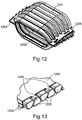
- the line routing device 100 forms a dust-tight, corrugated hose-like envelope and is in sections made up of two opposite, corrugated hose-like shell parts 1201; 1202, with different profiles, see FIG.2C , composed.
- the shell part 1201 outside can have a concave prestress.
- Each shell part 1201; 1202 has a fastening tape 1204 that is continuous in the longitudinal direction on the two long sides.
- the fastening tape 1204 each has a toothing with regularly arranged staples 1205 or teeth, which with a corresponding toothing with staples 1205 or teeth on the fastening strap 1204 of the opposite shell part 1201; 1202 cooperate in the manner of a zipper.
- the staples 1205 are shaped and arranged identically on both fastening straps 1204 of a shell part 1201, 1202. They are arranged at regular intervals or spaces so that they can interlock or interlock like a zipper.
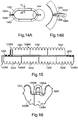
- the staples 1205 have an in FIG.13
- the effective cross-section shown in more detail corresponds at least approximately to the shape of an isosceles trapezoid, with the narrow side facing away from the shell part 1201, 1202 to be connected, ie the tapering legs wedge together when the shell parts 1201, 1202 are connected, FIG.13 shows.
- fastening straps 1204 can be fastened to one another by translation or force approximately perpendicular to the longitudinal direction of the shell parts 1201, 1202, i.e. without significant curvature of the parts.
- the staples 15 are produced integrally with the fastening straps 1204 or the plastic of the shell parts 1201, 1202. They protrude laterally outwardly transversely or precisely perpendicular to the longitudinal direction of the line routing device 100, quasi in extensions of the fastening straps 1204.
- FIG.14A-14b show in the area between the toothing with the staples 1205 and the transition to the corrugated tube-like casing of the shell parts 1201, 1202, a longitudinal groove 1206 in the fastening tape 1204 on one side.
- the longitudinal groove 1206 interacts positively with a corresponding spring 1207 on the shell part to be connected.
- Each shell part 1201, 1202 can have a longitudinal groove 1206 on one side in the fastening tape 1204 and a tongue 1207 on the other longitudinal side in the fastening tape 1204.
- the longitudinal groove 1206 and tongue 1207 are arranged symmetrically to the central plane that identical shell parts 1201 and 1202 can also be connected to one another by means of the tongue and groove connection.
- the connection of the longitudinal groove 1206 and the corresponding spring 1207 primarily has an effect that increases the tightness against the escape of particles, in particular with regard to the curvature in the deflection bend.
- FIG 16 illustrates a possible sealing of the front end regions 1208A, 1208B on the shell parts 1201, 1202.
- the sealing projection 1209A engages in the sealing groove 1209B in a form-fitting and / or force-fitting manner.
- FIG.13 The best recognizable joint between the fastening straps 1204 forms the neutral fiber here as well.
- ⁇ b> ⁇ u> Tag List ⁇ /u> ⁇ /b> FIG.1 322 longitudinal struts 100 cable routing device 331, 332 shell parts 101 Upper run 333 press studs 103 lower run 334 shots 104 deflection bend 335 interface 105 fixed junction 340 dividers 107 relatively movable junction B1 clear axial width (inside) B2 clear axial width (outside) 110 serving A deflection axis FIGS.
- FIGS. 4A-4C 400 cable routing device 408 interior FIG.2A-2C 410 corrugated hose 200 cable routing device 420 wave troughs 208 interior 440 support frame 210 serving 442 carriers 211 inside 444 cross ribs 212 outside 446 appendices 214 wave crests (outside) 215 strokes
- FIG.5 216 wave troughs (outside) 500 cable routing device 217 opposite end 510 corrugated hose 218 wave troughs (inside) 540 support frame 219 locking ring 542 carriers 220 wave crests (inside) 222 longitudinal struts
- FIG.6A-6C B1 clear axial width (inside) 600 cable routing device B2 clear axial width (outside) 608 interior 610 wrapping FIG.3A-3D 611 inside 300 cable routing device 612 outside 308 interior 618 wave troughs 310 serving 620 wave crests 311 inside 640 support frame 312 outside 642 carriers 314 wave crests (outside) 644, 645 cross ribs 315 strokes 316 wave troughs (outside)
- FIG.7A-7C 318 wave troughs (inside) 700 cable routing device 320 wave troughs (inside) 710 wrapping 711 inside 1054 fastening tape 712 outside 731, 732 shell parts
- FIG.11 760 cable routing 1100 cable routing device 762 section or link 1100A first longitudinal section 764 side panel 1100B second longitudinal section 766 carrier tape 1100C third longitudinal section 768 mounting tabs 1110 wrapping 769 fasteners 1131 shell part 770 connecting bridge 1132 shell part 771, 772 T-shaped bars 1141
Landscapes
- Engineering & Computer Science (AREA)
- General Engineering & Computer Science (AREA)
- Mechanical Engineering (AREA)
- Electric Cable Arrangement Between Relatively Moving Parts (AREA)
- Details Of Indoor Wiring (AREA)
- Supports For Pipes And Cables (AREA)
- Protection Of Pipes Against Damage, Friction, And Corrosion (AREA)
- Rigid Pipes And Flexible Pipes (AREA)
Priority Applications (1)
| Application Number | Priority Date | Filing Date | Title |
|---|---|---|---|
| EP20203219.9A EP3813213B1 (de) | 2014-09-18 | 2015-09-18 | Leitungsführungseinrichtung, insbesondere für reinraumanwendungen, sowie stützrippenmodul und bausatz hierfür |
Applications Claiming Priority (3)
| Application Number | Priority Date | Filing Date | Title |
|---|---|---|---|
| DE202014104458.2U DE202014104458U1 (de) | 2014-09-18 | 2014-09-18 | Energieführungseinrichtung insbesondere für Reinraumanwendungen |
| DE202015101688.3U DE202015101688U1 (de) | 2015-04-02 | 2015-04-02 | Wellschlauchartiges Schalenteil einer Leitungsführungseinrichtung, insbesondere für Reinraumanwendungen |
| PCT/EP2015/071449 WO2016042134A1 (de) | 2014-09-18 | 2015-09-18 | Leitungsführungseinrichtung, insbesondere für reinraumanwendungen, schalenteile und stützgerippe hierfür |
Related Child Applications (2)
| Application Number | Title | Priority Date | Filing Date |
|---|---|---|---|
| EP20203219.9A Division-Into EP3813213B1 (de) | 2014-09-18 | 2015-09-18 | Leitungsführungseinrichtung, insbesondere für reinraumanwendungen, sowie stützrippenmodul und bausatz hierfür |
| EP20203219.9A Division EP3813213B1 (de) | 2014-09-18 | 2015-09-18 | Leitungsführungseinrichtung, insbesondere für reinraumanwendungen, sowie stützrippenmodul und bausatz hierfür |
Publications (2)
| Publication Number | Publication Date |
|---|---|
| EP3195434A1 EP3195434A1 (de) | 2017-07-26 |
| EP3195434B1 true EP3195434B1 (de) | 2021-06-16 |
Family
ID=54145786
Family Applications (2)
| Application Number | Title | Priority Date | Filing Date |
|---|---|---|---|
| EP15763941.0A Active EP3195434B1 (de) | 2014-09-18 | 2015-09-18 | Leitungsführungseinrichtung, insbesondere für reinraumanwendungen, schalenteile und stützgerippe hierfür |
| EP20203219.9A Active EP3813213B1 (de) | 2014-09-18 | 2015-09-18 | Leitungsführungseinrichtung, insbesondere für reinraumanwendungen, sowie stützrippenmodul und bausatz hierfür |
Family Applications After (1)
| Application Number | Title | Priority Date | Filing Date |
|---|---|---|---|
| EP20203219.9A Active EP3813213B1 (de) | 2014-09-18 | 2015-09-18 | Leitungsführungseinrichtung, insbesondere für reinraumanwendungen, sowie stützrippenmodul und bausatz hierfür |
Country Status (9)
| Country | Link |
|---|---|
| US (2) | US10591089B2 (enExample) |
| EP (2) | EP3195434B1 (enExample) |
| JP (2) | JP6651508B2 (enExample) |
| KR (1) | KR102631647B1 (enExample) |
| CN (1) | CN107110299B (enExample) |
| ES (1) | ES2886156T3 (enExample) |
| MY (1) | MY182375A (enExample) |
| TW (1) | TWI689669B (enExample) |
| WO (1) | WO2016042134A1 (enExample) |
Families Citing this family (28)
| Publication number | Priority date | Publication date | Assignee | Title |
|---|---|---|---|---|
| SG11201806414UA (en) * | 2016-01-28 | 2018-08-30 | Igus Gmbh | Line guide device with electrical wear identification and radio circuit for it |
| US10128643B2 (en) * | 2016-10-13 | 2018-11-13 | Illinois Tool Works Inc. | Loom assembly providing improved electrical isolation |
| DE102017105787B3 (de) | 2017-03-17 | 2018-06-28 | Schlemmer Holding GmbH | Verbundschlauch |
| KR20190034874A (ko) | 2017-09-25 | 2019-04-03 | 엘케이테크넷(주) | 케이블 정렬 홀더 및 그 홀더를 포함한 케이블 |
| JP6838571B2 (ja) * | 2018-01-31 | 2021-03-03 | トヨタ自動車株式会社 | 伝動ベルト |
| DE202018106543U1 (de) | 2018-11-19 | 2019-12-20 | Igus Gmbh | System zur Leitungsüberwachung in einer Leitungsführungseinrichtung, insbesondere in einer Energieführungskette |
| CN109707996A (zh) * | 2018-12-24 | 2019-05-03 | 中国电建集团山东电力建设第一工程有限公司 | 一种电站锅炉安装用氧气皮带、乙炔皮带布线装置 |
| CN109630773B (zh) * | 2018-12-29 | 2020-01-21 | 燕山大学 | 一种凸轮式波形结构波纹金属软管及成形方法 |
| DE202019103276U1 (de) * | 2019-06-11 | 2020-02-20 | Igus Gmbh | Kompakte Leitungsschutzführung für Reinraumanwendungen sowie Hülleinheit und Klemmvorrichtung hierfür |
| DE202019100169U1 (de) * | 2019-01-14 | 2020-02-20 | Igus Gmbh | Kompakte flexible Leitungsschutzführung, insbesondere für Reinraumanwendungen |
| US12040570B2 (en) * | 2019-01-14 | 2024-07-16 | Igus Gmbh | Compact conduit for clean room applications, and casing and clamping fixtures for said conduit |
| DE202019103068U1 (de) * | 2019-05-29 | 2020-06-30 | Igus Gmbh | Leitungsführungseinrichtung für Reinraumanwendungen |
| CN210686430U (zh) | 2019-06-26 | 2020-06-05 | 米沃奇电动工具公司 | 用于鼓风机的波纹管和鼓风机 |
| DE202020102090U1 (de) * | 2020-04-15 | 2021-05-25 | Igus Gmbh | Leitungsführungsvorrichtung und modulare Endbefestigungen mit flexibler Umhüllung für Reinraumanwendungen |
| DE202019107118U1 (de) * | 2019-12-19 | 2021-03-22 | Igus Gmbh | Leitungsführung und Speichereinheit für eine Leitungsführung |
| JP7133596B2 (ja) * | 2020-09-10 | 2022-09-08 | 住友電装株式会社 | グロメット |
| CN112864976A (zh) * | 2021-02-26 | 2021-05-28 | 武立民 | 一种线管 |
| KR20230169287A (ko) | 2021-04-12 | 2023-12-15 | 이구스 게엠베하 | 에너지 체인에서 라인의 상태를 모니터링하기 위한 시스템 |
| DE202021101964U1 (de) | 2021-04-12 | 2022-07-18 | Igus Gmbh | System zur Zustandsüberwachung einer Leitung in einer Energieführungskette |
| DE202021106364U1 (de) | 2021-11-23 | 2022-07-26 | Igus Gmbh | System zur Zustandsüberwachung einer Leitung in einer Energieführungskette |
| DE202021104228U1 (de) | 2021-08-06 | 2022-09-07 | Igus Gmbh | System zur Abstützung einer beweglichen Leitungsaufnahmeeinrichtung, Energieführungskette oder dgl. |
| DE102022109963A1 (de) | 2022-04-25 | 2023-10-26 | Igus Gmbh | Verfahren und System zur indirekten Erkennung von Verschleiß einer Leitungsführungseinrichtung bzw. Energieführungskette |
| GB2621690A (en) * | 2022-07-04 | 2024-02-21 | Ocado Innovation Ltd | A cable router and a load handling device |
| CN115441351A (zh) * | 2022-08-04 | 2022-12-06 | 国网河北省电力有限公司保定供电分公司 | 一种封线装置 |
| CN117200101B (zh) * | 2023-09-16 | 2025-12-16 | 沃德拖链电缆保护系统(佛山)有限公司 | 保护套管及管线保护装置 |
| CN117739069A (zh) * | 2024-02-02 | 2024-03-22 | 广州希埃西托智能科技股份有限公司 | 能量链 |
| DE202024101891U1 (de) | 2024-04-16 | 2025-07-18 | Igus Gmbh | Leitungsführungsvorrichtung für Reinraumanwendungen sowie Halteelement dafür |
| EP4675142A1 (de) * | 2024-07-04 | 2026-01-07 | DOYMA GmbH & Co | Schutzrohranordnung zum durchführen einer leitung durch eine öffnung in einem wandabschnitt und verfahren zum installieren einer solchen schutzrohranordnung |
Family Cites Families (46)
| Publication number | Priority date | Publication date | Assignee | Title |
|---|---|---|---|---|
| US2585054A (en) * | 1949-03-10 | 1952-02-12 | Edward J Stachura | Flexible shield for electric conductors |
| US2613421A (en) | 1951-01-27 | 1952-10-14 | Flexico U S A S A | Slide fastener |
| DE1010486B (de) | 1956-02-24 | 1957-06-19 | Th Calow & Co | Einrichtung zum Bearbeiten mit einem Gewinde zu versehender Teile |
| US3060972A (en) | 1957-08-22 | 1962-10-30 | Bausch & Lomb | Flexible tube structures |
| DE2805832C3 (de) * | 1978-02-11 | 1981-02-05 | Kabelschlepp Gmbh, 5900 Siegen | Energieleitungsträger |
| DE3016628C2 (de) | 1980-04-30 | 1982-02-18 | Kabelschlepp Gmbh, 5900 Siegen | Energieleitungsträger |
| EP0038952B1 (de) * | 1980-04-30 | 1984-05-16 | Kabelschlepp Gesellschaft mit beschränkter Haftung | Energieleitungsträger |
| US4582281A (en) | 1983-06-06 | 1986-04-15 | Sine Products Company | Flexible support and carrier assembly |
| US4739801A (en) | 1985-04-09 | 1988-04-26 | Tysubakimoto Chain Co. | Flexible supporting sheath for cables and the like |
| DE19541928C1 (de) | 1995-11-10 | 1997-06-12 | Igus Gmbh | Energieführungskette |
| JP3547891B2 (ja) * | 1996-02-06 | 2004-07-28 | 株式会社国盛化学 | ケーブルチェーン |
| DE19837231A1 (de) * | 1998-08-17 | 2000-02-24 | Kabelschlepp Gmbh | Leitungsführungsanordnung |
| JP2000184552A (ja) | 1998-12-17 | 2000-06-30 | Shinagawa Shoko Kk | 保護カバー |
| DE19860948C2 (de) * | 1998-12-31 | 2002-02-14 | Igus Gmbh | Leitungsführungseinrichtung |
| DE29904796U1 (de) | 1999-03-17 | 1999-07-08 | Rüttiger, Michael, Dipl.-Ing., 80339 München | Energieführungsketten-System |
| JP2000346251A (ja) * | 1999-06-07 | 2000-12-15 | Osaka Gas Co Ltd | コルゲート管 |
| DE19962829A1 (de) | 1999-12-23 | 2001-08-23 | Kabelschlepp Gmbh | Strang und Verfahren zur Herstellung eines faserverstärkten Stranges einer Leitungsführungsanordnung |
| US6401320B1 (en) * | 2000-01-14 | 2002-06-11 | Manfred A. A. Lupke | Method of simultaneously making a plurality of metallic pipes |
| JP3356754B2 (ja) * | 2000-05-01 | 2002-12-16 | 株式会社椿本チエイン | ケーブル類の可撓支持案内装置 |
| DE10104846A1 (de) * | 2001-02-01 | 2002-08-08 | Flexatec Gmbh | Führungsanordnung zur Aufnahme und Führung von flexiblen Leitungen |
| JP3574080B2 (ja) | 2001-03-23 | 2004-10-06 | 未来工業株式会社 | 波付トラフ |
| DE20107003U1 (de) | 2001-04-23 | 2002-09-19 | Igus Spritzgußteile für die Industrie GmbH, 51147 Köln | Energieführungskette |
| JP3349146B1 (ja) * | 2001-09-06 | 2002-11-20 | 株式会社椿本チエイン | ケーブル類の保護案内ガイド |
| JP3349148B1 (ja) | 2001-12-11 | 2002-11-20 | 株式会社椿本チエイン | 密閉型ケーブルドラグチェーン |
| JP2004129479A (ja) | 2002-08-07 | 2004-04-22 | Yazaki Corp | ハーネス用外装部材とそれを用いたハーネス配索構造 |
| JP2004248367A (ja) * | 2003-02-12 | 2004-09-02 | Yazaki Corp | ハーネス用外装部材およびハーネス配索構造 |
| US7784259B2 (en) | 2004-01-23 | 2010-08-31 | A&A Manufacturing Co., Inc. | Monolithic enclosed cable carrier |
| DE202004005808U1 (de) | 2004-04-08 | 2004-06-17 | Igus Spritzgussteile für die Industrie GmbH | Energieführungskette |
| JP2005312256A (ja) * | 2004-04-26 | 2005-11-04 | Shizuo Ito | 配線保護筒 |
| JP2006042566A (ja) * | 2004-07-30 | 2006-02-09 | Yazaki Corp | 給電装置 |
| JP2006149012A (ja) * | 2004-11-17 | 2006-06-08 | Auto Network Gijutsu Kenkyusho:Kk | ワイヤーハーネス用コルゲートチューブの口開き防止部材 |
| JP2007252060A (ja) | 2006-03-15 | 2007-09-27 | Yazaki Corp | ハーネス外装部材 |
| CN2917042Y (zh) | 2006-07-14 | 2007-06-27 | 宁波华翔电子股份有限公司 | 拉链式波纹管 |
| DE102007017940A1 (de) | 2007-04-13 | 2008-10-16 | Igus Gmbh | Seitenwandsegment für eine Leitungsführungseinrichtung, Leitungsführungseinrichtung mit Seitenwandsegment und Verfahren zur Herstellung des Seitenwandsegmentes |
| JP2009254218A (ja) * | 2008-04-11 | 2009-10-29 | Molten Corp | 可撓性チューブ及びそれを備えたスライドドアのハーネス配設構造 |
| JP5405401B2 (ja) * | 2010-07-15 | 2014-02-05 | 宇部エクシモ株式会社 | ケーブルガイド |
| JP5079894B2 (ja) | 2011-02-15 | 2012-11-21 | 株式会社椿本チエイン | 多関節型ケーブル類保護案内装置 |
| US9173311B2 (en) * | 2011-12-19 | 2015-10-27 | Yazaki Corporation | Power supply apparatus for sliding structure |
| DE102012000798A1 (de) | 2012-01-18 | 2013-07-18 | Murrplastik Systemtechnik Gmbh | Vorrichtung zur Aufteilung des Innenraums eines Schutzschlauchs |
| JP5709799B2 (ja) | 2012-05-28 | 2015-04-30 | 株式会社椿本チエイン | ケーブル類保護案内部材 |
| JP5862537B2 (ja) * | 2012-10-05 | 2016-02-16 | 住友電装株式会社 | コルゲートチューブ及びコルゲートチューブ付ワイヤーハーネス |
| DE202012010236U1 (de) | 2012-10-26 | 2012-11-23 | Igus Gmbh | Energieführungskette mit Spann- bzw. Tragvorrichtung |
| KR101480355B1 (ko) * | 2013-03-12 | 2015-01-09 | 주식회사 에스제이엠 | 자동차 배기관용 플렉시블 튜브 |
| DE202013101203U1 (de) | 2013-03-20 | 2013-03-26 | Igus Gmbh | Energieführungskette insbesondere für Reinraumanwendungen |
| KR101570921B1 (ko) * | 2014-01-22 | 2015-11-20 | 주식회사 에스제이엠 | 자동차 배기관용 플렉시블 튜브 |
| DE202014104458U1 (de) | 2014-09-18 | 2014-09-25 | Igus Gmbh | Energieführungseinrichtung insbesondere für Reinraumanwendungen |
-
2015
- 2015-09-18 JP JP2017515165A patent/JP6651508B2/ja active Active
- 2015-09-18 MY MYPI2017700896A patent/MY182375A/en unknown
- 2015-09-18 KR KR1020177010422A patent/KR102631647B1/ko active Active
- 2015-09-18 TW TW104130857A patent/TWI689669B/zh active
- 2015-09-18 WO PCT/EP2015/071449 patent/WO2016042134A1/de not_active Ceased
- 2015-09-18 EP EP15763941.0A patent/EP3195434B1/de active Active
- 2015-09-18 ES ES15763941T patent/ES2886156T3/es active Active
- 2015-09-18 US US15/512,269 patent/US10591089B2/en active Active
- 2015-09-18 EP EP20203219.9A patent/EP3813213B1/de active Active
- 2015-09-18 CN CN201580062440.2A patent/CN107110299B/zh active Active
-
2020
- 2020-01-22 JP JP2020007968A patent/JP6979087B2/ja active Active
- 2020-03-17 US US16/821,418 patent/US11156310B2/en active Active
Non-Patent Citations (1)
| Title |
|---|
| None * |
Also Published As
| Publication number | Publication date |
|---|---|
| JP2020074678A (ja) | 2020-05-14 |
| ES2886156T3 (es) | 2021-12-16 |
| WO2016042134A1 (de) | 2016-03-24 |
| TW201616011A (zh) | 2016-05-01 |
| US10591089B2 (en) | 2020-03-17 |
| CN107110299B (zh) | 2019-08-16 |
| JP6979087B2 (ja) | 2021-12-08 |
| US11156310B2 (en) | 2021-10-26 |
| JP2017531141A (ja) | 2017-10-19 |
| EP3813213B1 (de) | 2025-11-05 |
| EP3813213C0 (de) | 2025-11-05 |
| TWI689669B (zh) | 2020-04-01 |
| CN107110299A (zh) | 2017-08-29 |
| US20170363229A1 (en) | 2017-12-21 |
| KR20170056009A (ko) | 2017-05-22 |
| EP3813213A1 (de) | 2021-04-28 |
| JP6651508B2 (ja) | 2020-02-19 |
| US20200224793A1 (en) | 2020-07-16 |
| MY182375A (en) | 2021-01-21 |
| KR102631647B1 (ko) | 2024-02-01 |
| EP3195434A1 (de) | 2017-07-26 |
Similar Documents
| Publication | Publication Date | Title |
|---|---|---|
| EP3195434B1 (de) | Leitungsführungseinrichtung, insbesondere für reinraumanwendungen, schalenteile und stützgerippe hierfür | |
| EP3912243B1 (de) | Kompakte leitungsschutzführung für reinraumanwendungen, sowie hülleinheit und klemmvorrichtung hierfür | |
| EP1256153B1 (de) | Energieführungskette | |
| EP2976548B1 (de) | Energieführungskette insbesondere für reinraumanwendungen | |
| EP1493215B1 (de) | Leitungsführungseinheit zur aktiven führung von leitungen, kabeln oder dergleichen | |
| EP1503107B2 (de) | Gelenkelement für Energieführungskette | |
| DE19710489A1 (de) | Faltbares Schutzelement für Leitungen | |
| EP4158223B1 (de) | Energieführungskette mit biegsamen gelenkverbindern, sowie seitenlaschen und gelenkverbinder hierfür | |
| EP3602709B1 (de) | Leitungsführungseinrichtung | |
| EP3555400B1 (de) | Schienengleiter für einen seilfensterheber eines kraftfahrzeugs | |
| EP3314148B1 (de) | Energieführungskette | |
| DE202019103276U1 (de) | Kompakte Leitungsschutzführung für Reinraumanwendungen sowie Hülleinheit und Klemmvorrichtung hierfür | |
| DE202014104458U1 (de) | Energieführungseinrichtung insbesondere für Reinraumanwendungen | |
| DE202019100169U1 (de) | Kompakte flexible Leitungsschutzführung, insbesondere für Reinraumanwendungen | |
| WO2022229219A1 (de) | Flexibler schlauch, insbesondere staubsaugerschlauch | |
| WO2026087767A1 (de) | Leitungsführung zum schutz mindestens einer leitung | |
| DE10205129A1 (de) | Tragband sowie Leitungsführungsanordnung zur aktiven Führung von Leitungen, Kabeln od. dgl. | |
| WO2023208527A1 (de) | Leitungsführungsvorrichtung und stützkette für reinraumanwendungen | |
| DE3636433C1 (en) | Support element |
Legal Events
| Date | Code | Title | Description |
|---|---|---|---|
| STAA | Information on the status of an ep patent application or granted ep patent |
Free format text: STATUS: THE INTERNATIONAL PUBLICATION HAS BEEN MADE |
|
| PUAI | Public reference made under article 153(3) epc to a published international application that has entered the european phase |
Free format text: ORIGINAL CODE: 0009012 |
|
| STAA | Information on the status of an ep patent application or granted ep patent |
Free format text: STATUS: REQUEST FOR EXAMINATION WAS MADE |
|
| 17P | Request for examination filed |
Effective date: 20170418 |
|
| AK | Designated contracting states |
Kind code of ref document: A1 Designated state(s): AL AT BE BG CH CY CZ DE DK EE ES FI FR GB GR HR HU IE IS IT LI LT LU LV MC MK MT NL NO PL PT RO RS SE SI SK SM TR |
|
| AX | Request for extension of the european patent |
Extension state: BA ME |
|
| DAV | Request for validation of the european patent (deleted) | ||
| DAX | Request for extension of the european patent (deleted) | ||
| STAA | Information on the status of an ep patent application or granted ep patent |
Free format text: STATUS: EXAMINATION IS IN PROGRESS |
|
| 17Q | First examination report despatched |
Effective date: 20190417 |
|
| GRAP | Despatch of communication of intention to grant a patent |
Free format text: ORIGINAL CODE: EPIDOSNIGR1 |
|
| STAA | Information on the status of an ep patent application or granted ep patent |
Free format text: STATUS: GRANT OF PATENT IS INTENDED |
|
| INTG | Intention to grant announced |
Effective date: 20200723 |
|
| GRAJ | Information related to disapproval of communication of intention to grant by the applicant or resumption of examination proceedings by the epo deleted |
Free format text: ORIGINAL CODE: EPIDOSDIGR1 |
|
| STAA | Information on the status of an ep patent application or granted ep patent |
Free format text: STATUS: EXAMINATION IS IN PROGRESS |
|
| INTC | Intention to grant announced (deleted) | ||
| GRAS | Grant fee paid |
Free format text: ORIGINAL CODE: EPIDOSNIGR3 |
|
| STAA | Information on the status of an ep patent application or granted ep patent |
Free format text: STATUS: GRANT OF PATENT IS INTENDED |
|
| GRAS | Grant fee paid |
Free format text: ORIGINAL CODE: EPIDOSNIGR3 |
|
| GRAS | Grant fee paid |
Free format text: ORIGINAL CODE: EPIDOSNIGR3 |
|
| GRAP | Despatch of communication of intention to grant a patent |
Free format text: ORIGINAL CODE: EPIDOSNIGR1 |
|
| GRAJ | Information related to disapproval of communication of intention to grant by the applicant or resumption of examination proceedings by the epo deleted |
Free format text: ORIGINAL CODE: EPIDOSDIGR1 |
|
| GRAL | Information related to payment of fee for publishing/printing deleted |
Free format text: ORIGINAL CODE: EPIDOSDIGR3 |
|
| STAA | Information on the status of an ep patent application or granted ep patent |
Free format text: STATUS: EXAMINATION IS IN PROGRESS |
|
| INTG | Intention to grant announced |
Effective date: 20210211 |
|
| INTG | Intention to grant announced |
Effective date: 20210216 |
|
| INTC | Intention to grant announced (deleted) | ||
| GRAP | Despatch of communication of intention to grant a patent |
Free format text: ORIGINAL CODE: EPIDOSNIGR1 |
|
| STAA | Information on the status of an ep patent application or granted ep patent |
Free format text: STATUS: GRANT OF PATENT IS INTENDED |
|
| GRAA | (expected) grant |
Free format text: ORIGINAL CODE: 0009210 |
|
| STAA | Information on the status of an ep patent application or granted ep patent |
Free format text: STATUS: THE PATENT HAS BEEN GRANTED |
|
| INTG | Intention to grant announced |
Effective date: 20210422 |
|
| AK | Designated contracting states |
Kind code of ref document: B1 Designated state(s): AL AT BE BG CH CY CZ DE DK EE ES FI FR GB GR HR HU IE IS IT LI LT LU LV MC MK MT NL NO PL PT RO RS SE SI SK SM TR |
|
| REG | Reference to a national code |
Ref country code: GB Ref legal event code: FG4D Free format text: NOT ENGLISH |
|
| REG | Reference to a national code |
Ref country code: CH Ref legal event code: EP |
|
| REG | Reference to a national code |
Ref country code: DE Ref legal event code: R096 Ref document number: 502015014833 Country of ref document: DE |
|
| REG | Reference to a national code |
Ref country code: AT Ref legal event code: REF Ref document number: 1403127 Country of ref document: AT Kind code of ref document: T Effective date: 20210715 |
|
| REG | Reference to a national code |
Ref country code: IE Ref legal event code: FG4D Free format text: LANGUAGE OF EP DOCUMENT: GERMAN |
|
| REG | Reference to a national code |
Ref country code: LT Ref legal event code: MG9D |
|
| PG25 | Lapsed in a contracting state [announced via postgrant information from national office to epo] |
Ref country code: FI Free format text: LAPSE BECAUSE OF FAILURE TO SUBMIT A TRANSLATION OF THE DESCRIPTION OR TO PAY THE FEE WITHIN THE PRESCRIBED TIME-LIMIT Effective date: 20210616 Ref country code: LT Free format text: LAPSE BECAUSE OF FAILURE TO SUBMIT A TRANSLATION OF THE DESCRIPTION OR TO PAY THE FEE WITHIN THE PRESCRIBED TIME-LIMIT Effective date: 20210616 Ref country code: BG Free format text: LAPSE BECAUSE OF FAILURE TO SUBMIT A TRANSLATION OF THE DESCRIPTION OR TO PAY THE FEE WITHIN THE PRESCRIBED TIME-LIMIT Effective date: 20210916 Ref country code: HR Free format text: LAPSE BECAUSE OF FAILURE TO SUBMIT A TRANSLATION OF THE DESCRIPTION OR TO PAY THE FEE WITHIN THE PRESCRIBED TIME-LIMIT Effective date: 20210616 |
|
| REG | Reference to a national code |
Ref country code: NL Ref legal event code: MP Effective date: 20210616 |
|
| PG25 | Lapsed in a contracting state [announced via postgrant information from national office to epo] |
Ref country code: LV Free format text: LAPSE BECAUSE OF FAILURE TO SUBMIT A TRANSLATION OF THE DESCRIPTION OR TO PAY THE FEE WITHIN THE PRESCRIBED TIME-LIMIT Effective date: 20210616 Ref country code: GR Free format text: LAPSE BECAUSE OF FAILURE TO SUBMIT A TRANSLATION OF THE DESCRIPTION OR TO PAY THE FEE WITHIN THE PRESCRIBED TIME-LIMIT Effective date: 20210917 Ref country code: NO Free format text: LAPSE BECAUSE OF FAILURE TO SUBMIT A TRANSLATION OF THE DESCRIPTION OR TO PAY THE FEE WITHIN THE PRESCRIBED TIME-LIMIT Effective date: 20210916 Ref country code: RS Free format text: LAPSE BECAUSE OF FAILURE TO SUBMIT A TRANSLATION OF THE DESCRIPTION OR TO PAY THE FEE WITHIN THE PRESCRIBED TIME-LIMIT Effective date: 20210616 Ref country code: SE Free format text: LAPSE BECAUSE OF FAILURE TO SUBMIT A TRANSLATION OF THE DESCRIPTION OR TO PAY THE FEE WITHIN THE PRESCRIBED TIME-LIMIT Effective date: 20210616 |
|
| REG | Reference to a national code |
Ref country code: ES Ref legal event code: FG2A Ref document number: 2886156 Country of ref document: ES Kind code of ref document: T3 Effective date: 20211216 |
|
| PG25 | Lapsed in a contracting state [announced via postgrant information from national office to epo] |
Ref country code: EE Free format text: LAPSE BECAUSE OF FAILURE TO SUBMIT A TRANSLATION OF THE DESCRIPTION OR TO PAY THE FEE WITHIN THE PRESCRIBED TIME-LIMIT Effective date: 20210616 Ref country code: CZ Free format text: LAPSE BECAUSE OF FAILURE TO SUBMIT A TRANSLATION OF THE DESCRIPTION OR TO PAY THE FEE WITHIN THE PRESCRIBED TIME-LIMIT Effective date: 20210616 Ref country code: SM Free format text: LAPSE BECAUSE OF FAILURE TO SUBMIT A TRANSLATION OF THE DESCRIPTION OR TO PAY THE FEE WITHIN THE PRESCRIBED TIME-LIMIT Effective date: 20210616 Ref country code: SK Free format text: LAPSE BECAUSE OF FAILURE TO SUBMIT A TRANSLATION OF THE DESCRIPTION OR TO PAY THE FEE WITHIN THE PRESCRIBED TIME-LIMIT Effective date: 20210616 Ref country code: NL Free format text: LAPSE BECAUSE OF FAILURE TO SUBMIT A TRANSLATION OF THE DESCRIPTION OR TO PAY THE FEE WITHIN THE PRESCRIBED TIME-LIMIT Effective date: 20210616 Ref country code: PT Free format text: LAPSE BECAUSE OF FAILURE TO SUBMIT A TRANSLATION OF THE DESCRIPTION OR TO PAY THE FEE WITHIN THE PRESCRIBED TIME-LIMIT Effective date: 20211018 Ref country code: RO Free format text: LAPSE BECAUSE OF FAILURE TO SUBMIT A TRANSLATION OF THE DESCRIPTION OR TO PAY THE FEE WITHIN THE PRESCRIBED TIME-LIMIT Effective date: 20210616 |
|
| PG25 | Lapsed in a contracting state [announced via postgrant information from national office to epo] |
Ref country code: PL Free format text: LAPSE BECAUSE OF FAILURE TO SUBMIT A TRANSLATION OF THE DESCRIPTION OR TO PAY THE FEE WITHIN THE PRESCRIBED TIME-LIMIT Effective date: 20210616 |
|
| REG | Reference to a national code |
Ref country code: DE Ref legal event code: R097 Ref document number: 502015014833 Country of ref document: DE |
|
| PLBE | No opposition filed within time limit |
Free format text: ORIGINAL CODE: 0009261 |
|
| STAA | Information on the status of an ep patent application or granted ep patent |
Free format text: STATUS: NO OPPOSITION FILED WITHIN TIME LIMIT |
|
| PG25 | Lapsed in a contracting state [announced via postgrant information from national office to epo] |
Ref country code: DK Free format text: LAPSE BECAUSE OF FAILURE TO SUBMIT A TRANSLATION OF THE DESCRIPTION OR TO PAY THE FEE WITHIN THE PRESCRIBED TIME-LIMIT Effective date: 20210616 |
|
| REG | Reference to a national code |
Ref country code: BE Ref legal event code: MM Effective date: 20210930 |
|
| 26N | No opposition filed |
Effective date: 20220317 |
|
| PG25 | Lapsed in a contracting state [announced via postgrant information from national office to epo] |
Ref country code: MC Free format text: LAPSE BECAUSE OF FAILURE TO SUBMIT A TRANSLATION OF THE DESCRIPTION OR TO PAY THE FEE WITHIN THE PRESCRIBED TIME-LIMIT Effective date: 20210616 Ref country code: AL Free format text: LAPSE BECAUSE OF FAILURE TO SUBMIT A TRANSLATION OF THE DESCRIPTION OR TO PAY THE FEE WITHIN THE PRESCRIBED TIME-LIMIT Effective date: 20210616 |
|
| PG25 | Lapsed in a contracting state [announced via postgrant information from national office to epo] |
Ref country code: LU Free format text: LAPSE BECAUSE OF NON-PAYMENT OF DUE FEES Effective date: 20210918 Ref country code: IE Free format text: LAPSE BECAUSE OF NON-PAYMENT OF DUE FEES Effective date: 20210918 Ref country code: BE Free format text: LAPSE BECAUSE OF NON-PAYMENT OF DUE FEES Effective date: 20210930 |
|
| PG25 | Lapsed in a contracting state [announced via postgrant information from national office to epo] |
Ref country code: HU Free format text: LAPSE BECAUSE OF FAILURE TO SUBMIT A TRANSLATION OF THE DESCRIPTION OR TO PAY THE FEE WITHIN THE PRESCRIBED TIME-LIMIT; INVALID AB INITIO Effective date: 20150918 |
|
| PG25 | Lapsed in a contracting state [announced via postgrant information from national office to epo] |
Ref country code: CY Free format text: LAPSE BECAUSE OF FAILURE TO SUBMIT A TRANSLATION OF THE DESCRIPTION OR TO PAY THE FEE WITHIN THE PRESCRIBED TIME-LIMIT Effective date: 20210616 |
|
| P01 | Opt-out of the competence of the unified patent court (upc) registered |
Effective date: 20230526 |
|
| PG25 | Lapsed in a contracting state [announced via postgrant information from national office to epo] |
Ref country code: MK Free format text: LAPSE BECAUSE OF FAILURE TO SUBMIT A TRANSLATION OF THE DESCRIPTION OR TO PAY THE FEE WITHIN THE PRESCRIBED TIME-LIMIT Effective date: 20210616 |
|
| PG25 | Lapsed in a contracting state [announced via postgrant information from national office to epo] |
Ref country code: MT Free format text: LAPSE BECAUSE OF FAILURE TO SUBMIT A TRANSLATION OF THE DESCRIPTION OR TO PAY THE FEE WITHIN THE PRESCRIBED TIME-LIMIT Effective date: 20210616 |
|
| PGFP | Annual fee paid to national office [announced via postgrant information from national office to epo] |
Ref country code: GB Payment date: 20240923 Year of fee payment: 10 |
|
| PGFP | Annual fee paid to national office [announced via postgrant information from national office to epo] |
Ref country code: AT Payment date: 20240918 Year of fee payment: 10 |
|
| REG | Reference to a national code |
Ref country code: CH Ref legal event code: U11 Free format text: ST27 STATUS EVENT CODE: U-0-0-U10-U11 (AS PROVIDED BY THE NATIONAL OFFICE) Effective date: 20251001 |
|
| PGFP | Annual fee paid to national office [announced via postgrant information from national office to epo] |
Ref country code: FR Payment date: 20250925 Year of fee payment: 11 |
|
| PG25 | Lapsed in a contracting state [announced via postgrant information from national office to epo] |
Ref country code: TR Free format text: LAPSE BECAUSE OF FAILURE TO SUBMIT A TRANSLATION OF THE DESCRIPTION OR TO PAY THE FEE WITHIN THE PRESCRIBED TIME-LIMIT Effective date: 20210616 |
|
| PGFP | Annual fee paid to national office [announced via postgrant information from national office to epo] |
Ref country code: DE Payment date: 20251128 Year of fee payment: 11 |
|
| PGFP | Annual fee paid to national office [announced via postgrant information from national office to epo] |
Ref country code: IT Payment date: 20250930 Year of fee payment: 11 |
|
| PGFP | Annual fee paid to national office [announced via postgrant information from national office to epo] |
Ref country code: CH Payment date: 20251001 Year of fee payment: 11 |
|
| PGFP | Annual fee paid to national office [announced via postgrant information from national office to epo] |
Ref country code: ES Payment date: 20251020 Year of fee payment: 11 |
|
| REG | Reference to a national code |
Ref country code: DE Ref legal event code: R081 Ref document number: 502015014833 Country of ref document: DE Owner name: IGUS SE & CO. KG, DE Free format text: FORMER OWNER: IGUS GMBH, 51147 KOELN, DE |