EP3193987B1 - Therapeutic agent delivery device - Google Patents
Therapeutic agent delivery device Download PDFInfo
- Publication number
- EP3193987B1 EP3193987B1 EP15808291.7A EP15808291A EP3193987B1 EP 3193987 B1 EP3193987 B1 EP 3193987B1 EP 15808291 A EP15808291 A EP 15808291A EP 3193987 B1 EP3193987 B1 EP 3193987B1
- Authority
- EP
- European Patent Office
- Prior art keywords
- spacer
- syringe
- barrel
- flange
- fluid
- Prior art date
- Legal status (The legal status is an assumption and is not a legal conclusion. Google has not performed a legal analysis and makes no representation as to the accuracy of the status listed.)
- Active
Links
Images


Classifications
-
- A—HUMAN NECESSITIES
- A61—MEDICAL OR VETERINARY SCIENCE; HYGIENE
- A61F—FILTERS IMPLANTABLE INTO BLOOD VESSELS; PROSTHESES; DEVICES PROVIDING PATENCY TO, OR PREVENTING COLLAPSING OF, TUBULAR STRUCTURES OF THE BODY, e.g. STENTS; ORTHOPAEDIC, NURSING OR CONTRACEPTIVE DEVICES; FOMENTATION; TREATMENT OR PROTECTION OF EYES OR EARS; BANDAGES, DRESSINGS OR ABSORBENT PADS; FIRST-AID KITS
- A61F9/00—Methods or devices for treatment of the eyes; Devices for putting in contact-lenses; Devices to correct squinting; Apparatus to guide the blind; Protective devices for the eyes, carried on the body or in the hand
- A61F9/0008—Introducing ophthalmic products into the ocular cavity or retaining products therein
-
- A—HUMAN NECESSITIES
- A61—MEDICAL OR VETERINARY SCIENCE; HYGIENE
- A61M—DEVICES FOR INTRODUCING MEDIA INTO, OR ONTO, THE BODY; DEVICES FOR TRANSDUCING BODY MEDIA OR FOR TAKING MEDIA FROM THE BODY; DEVICES FOR PRODUCING OR ENDING SLEEP OR STUPOR
- A61M5/00—Devices for bringing media into the body in a subcutaneous, intra-vascular or intramuscular way; Accessories therefor, e.g. filling or cleaning devices, arm-rests
- A61M5/178—Syringes
- A61M5/20—Automatic syringes, e.g. with automatically actuated piston rod, with automatic needle injection, filling automatically
- A61M5/2053—Media being expelled from injector by pressurised fluid or vacuum
-
- A—HUMAN NECESSITIES
- A61—MEDICAL OR VETERINARY SCIENCE; HYGIENE
- A61M—DEVICES FOR INTRODUCING MEDIA INTO, OR ONTO, THE BODY; DEVICES FOR TRANSDUCING BODY MEDIA OR FOR TAKING MEDIA FROM THE BODY; DEVICES FOR PRODUCING OR ENDING SLEEP OR STUPOR
- A61M5/00—Devices for bringing media into the body in a subcutaneous, intra-vascular or intramuscular way; Accessories therefor, e.g. filling or cleaning devices, arm-rests
- A61M5/178—Syringes
- A61M5/31—Details
- A61M5/3129—Syringe barrels
- A61M5/3137—Specially designed finger grip means, e.g. for easy manipulation of the syringe rod
-
- A—HUMAN NECESSITIES
- A61—MEDICAL OR VETERINARY SCIENCE; HYGIENE
- A61M—DEVICES FOR INTRODUCING MEDIA INTO, OR ONTO, THE BODY; DEVICES FOR TRANSDUCING BODY MEDIA OR FOR TAKING MEDIA FROM THE BODY; DEVICES FOR PRODUCING OR ENDING SLEEP OR STUPOR
- A61M5/00—Devices for bringing media into the body in a subcutaneous, intra-vascular or intramuscular way; Accessories therefor, e.g. filling or cleaning devices, arm-rests
- A61M5/178—Syringes
- A61M5/31—Details
- A61M5/3146—Priming, e.g. purging, reducing backlash or clearance
-
- A—HUMAN NECESSITIES
- A61—MEDICAL OR VETERINARY SCIENCE; HYGIENE
- A61M—DEVICES FOR INTRODUCING MEDIA INTO, OR ONTO, THE BODY; DEVICES FOR TRANSDUCING BODY MEDIA OR FOR TAKING MEDIA FROM THE BODY; DEVICES FOR PRODUCING OR ENDING SLEEP OR STUPOR
- A61M5/00—Devices for bringing media into the body in a subcutaneous, intra-vascular or intramuscular way; Accessories therefor, e.g. filling or cleaning devices, arm-rests
- A61M5/178—Syringes
- A61M5/31—Details
- A61M5/3148—Means for causing or aiding aspiration or plunger retraction
-
- A—HUMAN NECESSITIES
- A61—MEDICAL OR VETERINARY SCIENCE; HYGIENE
- A61M—DEVICES FOR INTRODUCING MEDIA INTO, OR ONTO, THE BODY; DEVICES FOR TRANSDUCING BODY MEDIA OR FOR TAKING MEDIA FROM THE BODY; DEVICES FOR PRODUCING OR ENDING SLEEP OR STUPOR
- A61M5/00—Devices for bringing media into the body in a subcutaneous, intra-vascular or intramuscular way; Accessories therefor, e.g. filling or cleaning devices, arm-rests
- A61M5/178—Syringes
- A61M5/31—Details
- A61M5/315—Pistons; Piston-rods; Guiding, blocking or restricting the movement of the rod or piston; Appliances on the rod for facilitating dosing ; Dosing mechanisms
- A61M5/31501—Means for blocking or restricting the movement of the rod or piston
- A61M5/31505—Integral with the syringe barrel, i.e. connected to the barrel so as to make up a single complete piece or unit
-
- A—HUMAN NECESSITIES
- A61—MEDICAL OR VETERINARY SCIENCE; HYGIENE
- A61M—DEVICES FOR INTRODUCING MEDIA INTO, OR ONTO, THE BODY; DEVICES FOR TRANSDUCING BODY MEDIA OR FOR TAKING MEDIA FROM THE BODY; DEVICES FOR PRODUCING OR ENDING SLEEP OR STUPOR
- A61M5/00—Devices for bringing media into the body in a subcutaneous, intra-vascular or intramuscular way; Accessories therefor, e.g. filling or cleaning devices, arm-rests
- A61M5/178—Syringes
- A61M5/31—Details
- A61M5/315—Pistons; Piston-rods; Guiding, blocking or restricting the movement of the rod or piston; Appliances on the rod for facilitating dosing ; Dosing mechanisms
- A61M5/31565—Administration mechanisms, i.e. constructional features, modes of administering a dose
- A61M5/31576—Constructional features or modes of drive mechanisms for piston rods
-
- A—HUMAN NECESSITIES
- A61—MEDICAL OR VETERINARY SCIENCE; HYGIENE
- A61M—DEVICES FOR INTRODUCING MEDIA INTO, OR ONTO, THE BODY; DEVICES FOR TRANSDUCING BODY MEDIA OR FOR TAKING MEDIA FROM THE BODY; DEVICES FOR PRODUCING OR ENDING SLEEP OR STUPOR
- A61M5/00—Devices for bringing media into the body in a subcutaneous, intra-vascular or intramuscular way; Accessories therefor, e.g. filling or cleaning devices, arm-rests
- A61M5/178—Syringes
- A61M5/31—Details
- A61M5/315—Pistons; Piston-rods; Guiding, blocking or restricting the movement of the rod or piston; Appliances on the rod for facilitating dosing ; Dosing mechanisms
- A61M5/31565—Administration mechanisms, i.e. constructional features, modes of administering a dose
- A61M5/3159—Dose expelling manners
- A61M5/31593—Multi-dose, i.e. individually set dose repeatedly administered from the same medicament reservoir
- A61M5/31595—Pre-defined multi-dose administration by repeated overcoming of means blocking the free advancing movement of piston rod, e.g. by tearing or de-blocking
-
- A—HUMAN NECESSITIES
- A61—MEDICAL OR VETERINARY SCIENCE; HYGIENE
- A61M—DEVICES FOR INTRODUCING MEDIA INTO, OR ONTO, THE BODY; DEVICES FOR TRANSDUCING BODY MEDIA OR FOR TAKING MEDIA FROM THE BODY; DEVICES FOR PRODUCING OR ENDING SLEEP OR STUPOR
- A61M5/00—Devices for bringing media into the body in a subcutaneous, intra-vascular or intramuscular way; Accessories therefor, e.g. filling or cleaning devices, arm-rests
- A61M5/178—Syringes
- A61M5/20—Automatic syringes, e.g. with automatically actuated piston rod, with automatic needle injection, filling automatically
- A61M2005/2086—Automatic syringes, e.g. with automatically actuated piston rod, with automatic needle injection, filling automatically having piston damping means, e.g. axially or rotationally acting retarders
-
- A—HUMAN NECESSITIES
- A61—MEDICAL OR VETERINARY SCIENCE; HYGIENE
- A61M—DEVICES FOR INTRODUCING MEDIA INTO, OR ONTO, THE BODY; DEVICES FOR TRANSDUCING BODY MEDIA OR FOR TAKING MEDIA FROM THE BODY; DEVICES FOR PRODUCING OR ENDING SLEEP OR STUPOR
- A61M5/00—Devices for bringing media into the body in a subcutaneous, intra-vascular or intramuscular way; Accessories therefor, e.g. filling or cleaning devices, arm-rests
- A61M5/178—Syringes
- A61M5/31—Details
- A61M5/315—Pistons; Piston-rods; Guiding, blocking or restricting the movement of the rod or piston; Appliances on the rod for facilitating dosing ; Dosing mechanisms
- A61M5/31501—Means for blocking or restricting the movement of the rod or piston
- A61M2005/31508—Means for blocking or restricting the movement of the rod or piston provided on the piston-rod
-
- A—HUMAN NECESSITIES
- A61—MEDICAL OR VETERINARY SCIENCE; HYGIENE
- A61M—DEVICES FOR INTRODUCING MEDIA INTO, OR ONTO, THE BODY; DEVICES FOR TRANSDUCING BODY MEDIA OR FOR TAKING MEDIA FROM THE BODY; DEVICES FOR PRODUCING OR ENDING SLEEP OR STUPOR
- A61M5/00—Devices for bringing media into the body in a subcutaneous, intra-vascular or intramuscular way; Accessories therefor, e.g. filling or cleaning devices, arm-rests
- A61M5/178—Syringes
- A61M5/31—Details
- A61M5/315—Pistons; Piston-rods; Guiding, blocking or restricting the movement of the rod or piston; Appliances on the rod for facilitating dosing ; Dosing mechanisms
- A61M5/31533—Dosing mechanisms, i.e. setting a dose
- A61M5/31535—Means improving security or handling thereof, e.g. blocking means, means preventing insufficient dosing, means allowing correction of overset dose
- A61M5/31536—Blocking means to immobilize a selected dose, e.g. to administer equal doses
- A61M2005/3154—Blocking means to immobilize a selected dose, e.g. to administer equal doses limiting maximum permissible dose
-
- A—HUMAN NECESSITIES
- A61—MEDICAL OR VETERINARY SCIENCE; HYGIENE
- A61M—DEVICES FOR INTRODUCING MEDIA INTO, OR ONTO, THE BODY; DEVICES FOR TRANSDUCING BODY MEDIA OR FOR TAKING MEDIA FROM THE BODY; DEVICES FOR PRODUCING OR ENDING SLEEP OR STUPOR
- A61M39/00—Tubes, tube connectors, tube couplings, valves, access sites or the like, specially adapted for medical use
- A61M39/10—Tube connectors; Tube couplings
- A61M2039/1077—Adapters, e.g. couplings adapting a connector to one or several other connectors
-
- A—HUMAN NECESSITIES
- A61—MEDICAL OR VETERINARY SCIENCE; HYGIENE
- A61M—DEVICES FOR INTRODUCING MEDIA INTO, OR ONTO, THE BODY; DEVICES FOR TRANSDUCING BODY MEDIA OR FOR TAKING MEDIA FROM THE BODY; DEVICES FOR PRODUCING OR ENDING SLEEP OR STUPOR
- A61M2210/00—Anatomical parts of the body
- A61M2210/06—Head
- A61M2210/0612—Eyes
-
- A—HUMAN NECESSITIES
- A61—MEDICAL OR VETERINARY SCIENCE; HYGIENE
- A61M—DEVICES FOR INTRODUCING MEDIA INTO, OR ONTO, THE BODY; DEVICES FOR TRANSDUCING BODY MEDIA OR FOR TAKING MEDIA FROM THE BODY; DEVICES FOR PRODUCING OR ENDING SLEEP OR STUPOR
- A61M5/00—Devices for bringing media into the body in a subcutaneous, intra-vascular or intramuscular way; Accessories therefor, e.g. filling or cleaning devices, arm-rests
- A61M5/178—Syringes
- A61M5/31—Details
- A61M5/315—Pistons; Piston-rods; Guiding, blocking or restricting the movement of the rod or piston; Appliances on the rod for facilitating dosing ; Dosing mechanisms
- A61M5/31565—Administration mechanisms, i.e. constructional features, modes of administering a dose
- A61M5/31576—Constructional features or modes of drive mechanisms for piston rods
- A61M5/31578—Constructional features or modes of drive mechanisms for piston rods based on axial translation, i.e. components directly operatively associated and axially moved with plunger rod
- A61M5/3158—Constructional features or modes of drive mechanisms for piston rods based on axial translation, i.e. components directly operatively associated and axially moved with plunger rod performed by axially moving actuator operated by user, e.g. an injection button
Definitions
- EP 1911480 A1 discloses a syringe for administering multiple doses with detachable dose limiting means.
- EP 2708254 A1 discloses a syringe with a pair of spacers which can fit one above the other with parts that connect to each other and the plunger in order to limit the movement of the syringe plunger.
- proximal and distal are defined herein relative to a surgeon or other operator grasping a surgical instrument having a distal surgical end effector.
- proximal refers the position of an element closer to the surgeon or other operator and the term “distal” refers to the position of an element closer to the surgical end effector of the surgical instrument and further away from the surgeon or other operator.
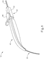
- FIGS. 1-4 show an exemplary instrument (10) that is configured for use in a procedure for the subretinal administration of a therapeutic agent to an eye of a patient from a suprachoroidal approach.
- Instrument (10) comprises a flexible cannula (20), a body (40), and a slidable (60).
- Cannula (20) extends distally from body (40) and has a generally rectangular cross section.
- Cannula (20) is generally configured to support a needle (30) that is slidable within cannula (20), as will be described in greater detail below.
- cannula (20) comprises a flexible material such as Polyether block amide (PEBA), which may be manufactured under the trade name PEBAX.
- PEBA Polyether block amide
- cannula (20) has a cross-sectional profile dimension of approximately 2.0 mm by 0.8 mm, with a length of approximately 80 mm. Alternatively, any other suitable dimensions may be used.
- cannula (20) is flexible enough to conform to specific structures and contours of the patient's eye, yet cannula (20) has sufficient column strength to permit advancement of cannula (20) between the sclera and choroid of patient's eye without buckling.
- the durometer of the material used to construct cannula (20) at least partially characterizes the flexibility of cannula (20).
- the material that is used to form cannula (20) may have a shore hardness of approximately 27D, approximately 33D, approximately 42D, approximately 46D, or any other suitable shore hardness.
- shore hardness may fall within the range of approximately 27D to approximately 46D; or more particularly within the range of approximately 33D to approximately 46D; or more particularly within the range of approximately 40D to approximately 45D.
- the particular cross-sectional shape of cannula (20) may also at least partially characterize the flexibility of cannula (20).
- the stiffness of needle (30) disposed within cannula (20) may at least partially characterize the flexibility of cannula (20).
- the flexibility of cannula (20) may be quantified by calculating a flexural stiffness for cannula (20). Flexural stiffness is calculated by the product of the elastic modulus and the area moment of inertia.
- one exemplary material that may be used to form cannula (20) may have a shore hardness of D27, an elastic modulus (E) of 1.2x10 7 N/m 2 , and an area moment of inertia (I x ) of 5.52x10 -14 m 4 , providing a calculated flexural stiffness about the x-axis at 0.7x10 -6 Nm 2 .
- cannula (20) may have a shore hardness of D46, an elastic modulus (E) of 17.0x10 7 N/m 2 , and an area moment of inertia (I x ) of 5.52x10 -14 m4, providing a calculated flexural stiffness about the x-axis at 9.4x10 -6 Nm 2 .
- flexural stiffness (EI) is calculated experimentally by deflecting cannula (20) having a fixed span (L) a set distance to yield a predetermined amount of deflection ( ⁇ ). The amount of force (F) required for such a deflection may then be recorded.
- cannula (20) may have a span of 0.06 m and may be deflected for a given distance.
- one exemplary material that may be used to form cannula (20) may require a force of 0.0188 N to achieve a deflection of 0.0155 m, providing a calculated flexural stiffness about the x-axis of 5.5x10 -6 Nm 2 .
- cannula (20) may require a force of 0.0205 N to achieve a deflection of 0.0135 m, providing a calculated flexural stiffness about the x-axis of 6.8x10 -6 Nm 2 .
- a force of 0.0199 N to achieve a deflection of 0.0099 m may be required to achieve a deflection of 9.1x10 -6 Nm 2 .
- cannula (20) may require a force of 0.0241 N to achieve a deflection of 0.0061 m, providing a calculated flexural stiffness about the x-axis of 1.8x10 -6 Nm 2 .
- a force of 0.0190 N to achieve a deflection 0.0081 m may be required to achieve a deflection 0.0081 m, providing a calculated flexural stiffness about the x-axis of 1.0x10 -6 Nm 2 .
- cannula (20) may require a force of 0.0233 N to achieve a deflection of 0.0147 m, providing a calculated flexural stiffness about the x-axis of 7.1x10 -6 Nm 2 .
- a force of 0.0192 N to achieve a deflection of 0.0122 may be required to achieve a deflection of 0.0122, providing a calculated flexural stiffness about the x-axis of 7.1x10 -6 Nm 2 .
- cannula (20) may require a force of 0.0201 N to achieve a deflection of 0.0201, providing a calculated flexural stiffness about the x-axis of 4.5x10 -6 Nm 2 .
- the flexural stiffness of cannula (20) may fall within the range of approximately 1.0x10 -6 Nm 2 to approximately 9.1x10 -6 Nm 2 .
- Needle (30) may have a flexural stiffness that differs from the flexural stiffness of cannula (20).
- needle (30) may be formed of a nitinol material that has an elastic modulus (E) of 7.9x10 10 N/m 2 , and an area moment of inertia (I x ) of 2.12x10 -17 m 4 , providing a calculated flexural stiffness about the x-axis at 1.7x10 -6 Nm 2 .
- the flexural stiffness of needle (30) may fall within the range of approximately 0.5x10 -6 Nm 2 to approximately 2.5x10 -6 Nm 2 ; or more particularly within the range of approximately 0.75x10 -6 Nm 2 to approximately 2.0x10 -6 Nm 2 ; or more particularly within the range of approximately 1.25x10 -6 Nm 2 to approximately 1.75x10 -6 Nm 2 .
- needle guide (80) defines an internal lumen (84) that is configured to slidably receive needle (30).
- internal lumen (84) includes a generally straight proximal portion (86) and a curved distal portion (88).
- Straight proximal portion (86) corresponds to the longitudinal axis (LA) of cannula (20), while curved distal portion (88) curves upwardly away from the longitudinal axis of cannula (20).
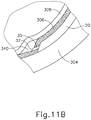
- Curved distal portion (88) of the present example is curved to direct needle (30) along an exit axis (EA) that extends distally from cannula (20) at an angle of approximately 7° to approximately 9° relative to the longitudinal axis (LA) of cannula (20). It should be understood that such an angle may be desirable to deflect needle (30) in a direction to ensure penetration of needle into the choroid (306) and to minimize the possibility of needle (30) continuing beneath the choroid (306) through the suprachoroidal space (as opposed to penetrating through the choroid (306)) and the possibility of retinal perforation.
- curved distal portion (88) may urge needle (30) to exit cannula (20) along an exit axis (EA) that is oriented at an angle within the range of approximately 5° to approximately 30° relative to the longitudinal axis (LA) of cannula (20); or more particularly within the range of approximately 5° to approximately 20° relative to the longitudinal axis (LA) of cannula (20); or more particularly within the range of approximately 5° to approximately 10° relative to the longitudinal axis (LA) of cannula (20).
- EA exit axis
- Needle (30) is in the form of an inner cannula has a sharp distal end (32) and defines an internal lumen (34).
- Distal end (32) of the present example has a lancet configuration.
- distal end (32) has a tri-bevel configuration or any other configuration as described in U.S. Pat. App. No. 14/619,256 , entitled “Method and Apparatus for Suprachoroidal Administration of Therapeutic Agent," filed February 11, 2015. Still other suitable forms that distal end (32) may take will be apparent to those of ordinary skill in the art in view of the teachings herein.
- the inner diameter of needle (30) may fall within the range of approximately 50 ⁇ m to approximately 200 ⁇ m; or more particularly within the range of approximately 50 ⁇ m to approximately 150 ⁇ m; or more particularly within the range of approximately 75 ⁇ m to approximately 125 ⁇ m.
- body (40) is generally shaped as an elongate rectangle with a curved distal end.
- the particular shape of body (40) that is shown is configured to be grasped by an operator.
- body (40) may be mounted on a support device or robotic arm for ease of positioning instrument (10), as described in U.S. Pat. App. No. 14/619,256 , entitled “Method and Apparatus for Suprachoroidal Administration of Therapeutic Agent," filed February 11, 2015.
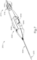
- Actuation assembly (60) includes an actuation member (62) and a locking member (66).
- Locking member (66) is removably attachable to body engagement portion (50), between body (40) and actuation member (62).
- locking member (66) fills a space between body (40) and actuation member (62) to prevent actuation member (62) from being advanced distally relative to body (40).
- locking member (66) can be removed to selectively permit actuation member (62) to be advanced distally relative to body (40).
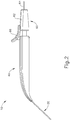
- FIGS. 2-4 show an exemplary actuation of instrument (10).
- needle (30) is initially retracted into cannula (20) and locking member (66) is positioned between body (40) and actuation member (62), thereby preventing advancement of actuation member (62).
- cannula (20) may be positioned within an eye of a patient as will be described in greater detail below.
- an operator may desire to advance needle (30) relative to cannula (20).
- an operator may first remove locking member (66) by pulling locking member (66) away from instrument (10), as can be seen in FIG. 3 .
- actuation member (62) may be moved or translated relative to body (40) to advance needle (30) relative to cannula (20) as described in U.S. Pat. App. No. 14/619,256 , entitled “Method and Apparatus for Suprachoroidal Administration of Therapeutic Agent," filed February 11, 2015.
- Actuation member (62) of the present example is only configured to translate needle (30) and not rotate needle (30). In other examples, it may be desirable to rotate needle (30). Accordingly, alternative examples may include features in actuation member (62) to rotate and translate needle (30).
- advancement of actuation member (62) into contact with body (40) as shown in FIG. 4 corresponds to advancement of needle (30) to a position relative to cannula (20) to a predetermined amount of penetration within an eye of a patient.
- instrument (10) is configured such that an operator only has to advance actuation member (62) into contact with body (40) to properly position needle (30) within an eye of a patient.
- the predetermined amount of advancement of needle (30) relative to cannula (20) is between approximately 0.25 mm to approximately 10 mm; or more particularly within the range of approximately 0.1 mm to approximately 10 mm; or more particularly within the range of approximately 2 mm to approximately 6 mm; or more particularly to approximately 4 mm.
- contact between actuation member (62) and body (40) may have no particular significance besides the maximum advancement of needle (30) relative to cannula (20).
- instrument (10) may be equipped with certain tactile feedback features to indicate to an operator when needle (30) has been advanced to certain predetermined distances relative to cannula (20). Accordingly, an operator may determine the desired depth of penetration of needle (30) into a patient's eye based on direct visualization of indicia on instrument and/or based on tactile feedback from instrument (10).
- tactile feedback features may be combined with the present example, as will be apparent to those of ordinary skill in the art in view of the teachings herein.
- Actuation member (62) includes a lumen (not shown) extending longitudinally though actuation member (62).
- the lumen of actuation member (62) is configured to receive supply tube (64).
- supply tube (64) connects to the fluid coupling member of body engagement portion (not shown), extends proximally through body engagement portion, proximally through actuation member (62), and proximally out through the proximal end of actuation member (62).
- supply tube (64) defines a conduit through actuation member (62) to needle (30) such that fluid may be injected via supply tube (64) through needle (30) to an injection site.
- the proximal end of supply tube (64) connects to a fluid source such as a syringe, an automated or semi-automated injector, or any other suitable fluid source.
- a fluid source such as a syringe, an automated or semi-automated injector, or any other suitable fluid source.
- the proximal end of supply tube (64) may include a luer fitting and/or any other suitable kind of fitting to enable supply tube (64) to be releasably coupled with a fluid source.
- instruments described herein it may be desirable to vary certain components or features of the instruments described herein. For instance, it may be desirable to utilize instruments similar to instrument (10) with alternative mechanisms to actuate needle (30). Yet in other examples, it may be desirable to utilize instruments similar to instrument (10) equipped with different cannula (20) or needle (30) geometries. Instruments having the above referenced variations may be desirable for different surgical procedures, or surgical procedures similar to the procedure discussed above, to engage tissue structures having varying physical properties. While certain examples of variations are described herein, it should be understood that the instruments described herein may include any other alternative features as will be apparent to those of ordinary skill in the art in view of the teachings herein.
- instrument (2010) of this example comprises a cannula (2020), a body (2040), and an actuation assembly (2100).
- Cannula (2020) includes a nitinol needle (2030) extending therethrough and is substantially the same as cannula (20) described above.
- cannula (2020) and needle (2030) are substantially identical to cannula (20) and needle (30) described above.
- actuation assembly (2100) is rotated to actuate the valve assembly, and needle (2030), the valve assembly and needle (2030) remain substantially rotationally stationary relative to body (2040).
- rotation member (2110) of the present example is described as being manually rotated, rotation member (2110) may be rotated via a motor and/or some other motive source.
- translation of needle (2030) may be mechanically/electrically driven via a servomotor.
- Protrusions (230) are spaced a predetermined distance from upper guide portion (222).
- protrusions (230) form a pattern that may correspond to relevant marks for use during the method described below.
- Protrusions (230) of the present example comprise four suture loop protrusions (230a-230h) and two sclerotomy protrusions (230i, 230j).
- Suture loop protrusions (230a-320h) and sclerotomy protrusions (230i, 230j) extend outwardly from body (220) an equal distance such that protrusions (230) collectively maintain the curvature defined by body (220).
- Shaft (240) extends proximally from body (220). Shaft (240) is configured to permit an operator to grasp template (210) and manipulate body (220). In the present example, shaft (240) is integral with body (220). In other examples, shaft (240) may be selectively attachable to body by a mechanical fastening means such as a threaded coupling or a mechanical snap fit, etc. In some versions, an operator may be presented with a kit comprising a shaft (240) and a plurality of bodies (220). The bodies (220) may have different curvatures to correspond with different eyeballs having different radii of curvature.
- suture loop protrusions (232) and sclerotomy protrusions (234) each correspond to a particular portion of the method described below.
- an operator may coat protrusions (230) with a biocompatible pigment or ink by pressing protrusions (230) onto a pigment or ink pad (250), by brushing the pigment or ink onto protrusions (230), or by otherwise applying the pigment or ink to protrusions (230).
- protrusions (230) Once protrusions (230) have received the pigment or ink, an operator may mark an eye of a patent by pressing protrusions (230) of template (210) onto the eye of the patient, as will be described in greater detail below. Once template (210) is removed from an eye of a patient, the pigment from protrusions may remain adhered to the eye to mark particular points of interest, as will be described in greater detail below.
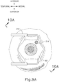
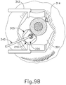
- eye chandelier port (314) is positioned to direct light onto the interior of eye (314) to illuminate at least a portion of the retina (e.g., including at least a portion of the macula). As will be understood, such illumination corresponds to an area of eye (301) that is being targeted for delivery of therapeutic agent.
- only chandelier port (314) is inserted at this stage, without yet inserting an optical fiber (315) into port (314).
- an optical fiber (315) may be inserted into chandelier port (314) at this stage.
- a microscope may optionally be utilized to visually inspect the eye to confirm proper positioning of eye chandelier port (314) relative to the target site.
- the target region may be identified by a relative lack of retinal pigmentation.
- FIG 9A shows a particular positioning of eye chandelier port (314), it should be understood that eye chandelier port (314) may have any other positioning as will be apparent to those of ordinary skill in the art in view of the teachings herein.
- a blunt dissection may optionally be performed to locally separate sclera (304) from choroid (306). Such a dissection may be performed using a small blunt elongate instrument, as will be apparent to those of ordinary skill in the art in view of the teachings herein.
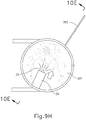
- cannula (20) of instrument (10) may insert cannula (20) of instrument (10) through incision (316) and into the space between sclera (304) and choroid (306).
- cannula (20) is directed through guide loops (336) of suture loop assembly (330) and into incision (316).
- guide loops (336) may stabilize cannula (20).
- guide loops (336) maintain cannula (20) in a generally tangential orientation relative to incision (316). Such tangential orientation may reduce trauma as cannula (20) is guided through incision (316) to stabilize cannula (20) and to prevent damage to surrounding tissue.
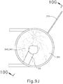
- cannula (20) is at least partially inserted into eye (301), an operator may insert an optical fiber (315) into eye chandelier port (314) the fiber (315) had not yet been inserted at this stage.
- eye chandelier port (314) With eye chandelier port (314) in place and assembled with optical fiber (315), an operator may activate eye chandelier port (314) by directing light through optical fiber (315) to provide illumination of eye (301) and thereby visualize the interior of eye (301). Further adjustments to the positioning of cannula (20) may optionally be made at this point to ensure proper positioning relative to the area of geographic atrophy of retina (308).
- the operator may wish to rotate the eye (301), such as by pulling on sutures (334, 339), to direct the pupil of the eye (301) toward the operator in order to optimize visualization of the interior of the eye (301) via the pupil.
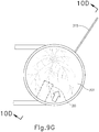
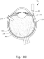
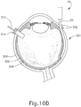
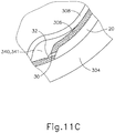
- FIGS. 9G and 10C-10D show cannula (20) as it is guided between sclera (304) and choroid (306) to the delivery site for the therapeutic agent.
- the delivery site corresponds to a generally posterior region of eye (301) adjacent to an area of geographic atrophy of retina (308).
- the delivery site of the present example is superior to the macula, in the potential space between the neurosensory retina and the retinal pigment epithelium layer.
- FIG. 9G shows eye (301) under direct visualization through a microscope directed through the pupil of eye (301), with illumination provided through fiber (315) and port (314).
- cannula (20) is at least partially visible through a retina (308) and choroid (306) of eye (301).
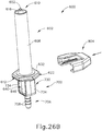
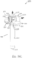
- Proximal end (412) of syringe barrel (408) comprises a flange (422) that extends radially outwardly relative to a longitudinal axis (424) of syringe (402) and acts as a finger grip when a user holds syringe (402).
- flange (422) includes two parallel opposing flat edges (426a, 426b) and two opposing curved edges (428a, 428b) that each extend between the flat edges (426a, 426b). Curved edges (428a, 428b) extend around axis (424).
- Flange (422) further includes a proximal side (430) facing away from barrel (408) and a distal side (432) facing toward barrel (408).
- recess (458) defines a shape that complements at least a portion of the shape of the shaft (440), such that recess (458) is configured to receive at least a portion of shaft (440).
- recess (458) defines part of a cross shape having a first recessed portion (460) that extends perpendicularly to plane (448); and a second recessed portion (462) that extends perpendicularly from the first recessed portion (460) toward handle (450) and along plane (448).
- Engagement portion (452) defines a first lip (464) on the first side (454) extending inwardly toward plane (448) and a second lip (466) on second side (456) extending inwardly towards plane (448).
- tab (404) may adjust tab (404) such that the bottom flange (470) abuts flange (422) of syringe (402).
- the operator may place tab (404) into engagement with shaft (440) such that upper flange (468) of tab generally abuts thumb flange (438).
- the operator may place tab (404) into engagement with shaft (440) at an intermediate position along shaft between flange (422) and thumb flange (438).
- tab (404) is configured to engage shaft (440) in a manner that allows tab to slide relative to shaft (440) and that allows shaft (440) to slide relative to tab (404).
- Tab (404) may be removed from engagement with shaft (440) by, for example, the operator pulling tab (404) away from shaft along a path that is transverse to the longitudinal axis of shaft (440), with a sufficient force to overcome the engagement between engagement portion (452) and shaft (440). Absent the force, engagement portion (440) is configured to maintain the engagement between tab (404) and shaft (440). Upon being subjected to such a removal force, however, in the present example, lips (464, 466) cam against third and fourth arms (446c, 446d), respectively, and first and second sides (454, 456) are urged away from plane (448).
- the operator may push plunger assembly (406) distally relative to barrel (408). For at least a first part of this advancement, the operator may orient syringe (402) upwardly such that any air in lumen (420) will be positioned at distal end (410). Thus, piston (434) will first purge the air out of the space in lumen (420) defined between piston (434) and distal end (410) as plunger assembly (406) is distally advanced through a first range of motion. As the operator continues to advance plunger assembly (406), some fluid may be ejected out through opening (414).
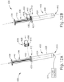
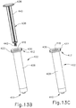
- FIGS. 13A-14B show an exemplary alternative method of using syringe (402) and plunger assembly (406), to prepare syringe (402) for use in a system with one or more powered components as described in greater detail below.
- This method is substantially similar to the method described above with respect to FIGS. 12A-12E .
- the method shown in FIGS. 13A-14B begins at after reaching the stage shown in FIG. 12C and described above, where plunger assembly (406) has reached a predetermined depth of advancement into syringe (402), as governed by tab (404), resulting in a predetermined volume of fluid in syringe (402). While not shown in FIGS.
- instrument (1000) may be coupled with distal end (410) of syringe (402) during the stages shown in FIGS. 13A-14B .
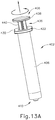
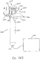
- the operator instead of the operator advancing plunger assembly (406) further distally in order to expel the fluid from syringe (402), the operator decouples rod (440) from piston (434) by rotating rod (440) to unscrew threaded portion (442) from threaded portion (444).
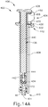
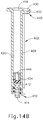
- the operator may fully remove rod (440) from syringe (402) as shown in FIGS. 13B-13C and 14B , then set rod (440) aside.
- Piston (434) will remain in place in barrel (408), as shown in FIG. 14B .
- barrel (408) may protect piston (434) from inadvertent engagement with other objects, such that piston (434) may remain in the same position within barrel (408) until piston (434) is acted upon by a pressurized medium as will be described in greater detail below.
- piston (434) remaining in the same position within barrel (408), the same predetermined amount of fluid may also remain within barrel (408).
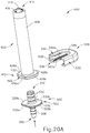
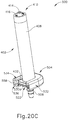
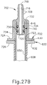
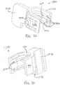
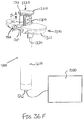
- FIGS. 20A-21C show how an adapter (502) and a collar (504) may be secured to syringe (402) to form an assembly (500).
- Adapter (502) enables syringe (402) to be coupled with a system with one or more powered components as described in greater detail below.
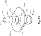
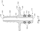
- FIGS. 16-17 show adapter (502) in greater detail.
- Adapter (502) may be coupled with proximal end (412) of syringe (402) after syringe (402) reaches the state shown in FIGS. 13C and 14B .
- Adapter (502) of this example has a proximal end (506) and a distal end (510).
- Proximal end (506) has a barbed connection feature (508) that is adapted for connection to tubing, for example.
- Distal end (510) comprises a tubular member (512) having annular recesses (514).
- a lumen (516) extends between a first opening (518) at proximal end (506) and a second opening (520) at distal end (510).
- a flange (522) is disposed between proximal end (506) and distal end (510) of syringe adapter (502).
- Flange (522) includes a proximal side (524) facing proximal end (506) of syringe adapter (502) and a distal side (526) facing distal end (510).
- Flange (522) includes a pair of opposing curved edges (528a, 528b) and a pair of opposing straight edges (530a, 530b). Each straight edge (530, 530b) is disposed between opposing ends of the curved edges (528a, 528b).
- syringe adapter (502) is a single unitary body, but in other examples may comprise multiple portions coupled together. Various other suitable ways in which syringe adapter (502) may be configured will be apparent to a person skilled in the art in view of the teachings herein.
- annular recesses (514) each receive sealing elements, which in the present example include an O-ring (532) received in each of the annular recesses (514).
- Tubular member (512) is sized and configured to be received in second opening (418) of syringe barrel (408) once, for example, plunger rod (436) is decoupled from piston (434) as shown in FIGS. 13C and 14B .
- O-rings (532) are configured to provide a fluid tight seal between lumen (420) of syringe (402) and syringe adapter (502) to prevent the escape of fluid pressure from second end of syringe (402).
- proximal end (506) of syringe adapter (502) may be coupled to a source of pressurized air or other fluid and distal end (510) of syringe adapter (502) may be received in second end of syringe (402). Therefore, pressurized air or fluid may be communicated to lumen (420) of syringe (402) via adapter (502), proximal to piston (434), and cause the advancement of piston (434) within syringe (402) to thereby dispense fluid from syringe (402).
- adapter (502) may be used to communicate suction to lumen (420) of syringe (402), proximal to piston (434), and cause the retraction of piston (434) within syringe (402) to thereby draw fluid into syringe (402).
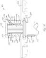
- FIGS. 18-19 show collar (504) in greater detail.
- Collar (504) may be used to secure adapter (502) to proximal end (412) of syringe (402) and thereby prevent movement of adapter (502) relative to syringe (402).
- Collar (504) is configured to keep adapter (502) secured to syringe (412) even when adapter (502) is communicating a pressurized medium to syringe (402) at a fluid pressure between approximately 20 psi and approximately 40 psi.
- Collar (504) of the present example includes a generally U-shaped body defined by a U-shaped wall (532), a first, upper flange (534) extending perpendicularly from the wall (532) and an opposing second, lower flange (536) extending perpendicularly from the wall (532). There is a curved, filleted edge (538, 540) between the wall (532) and each of the first and second flanges (534, 536), respectively.
- First flange (534) includes a U-shaped inner edge (542) with opposing straight portions (544a, 544b) and a curved portion (546) between the straight portions (544a, 544b).
- Second flange (536) also includes an inner edge (548) with opposing straight portions (550a, 550b) and a curved portion (552) between the straight portions (550a, 550b).
- First flange (534) and second flange (536) each include a respective inner portion (554, 556).
- Wall (532) includes an inner wall portion (558) that extends between and perpendicularly to inner flange portions (554, 556).
- inner flange portions (554, 556) and inner wall portion (558) define a U-shaped cavity.
- Inner portion (554) of first flange (534) includes a plurality of ramps (560a-c) extending toward inner portion (556) of second flange (536), while inner portion (556) of second flange (536) includes a plurality of ramps (562a-c) extending toward inner portion (554) of first flange (534).
- Each of the ramps (560a-c, 562a-c) extends parallel to edges (544a-b, 550a-b).
- Ramps (560a, 560c) extend from near a front portion of collar (502) along opposing sides of inner portion (554) of flange (534) toward a rear portion of collar, while ramps (562a, 562c) extend from near a front portion of collar (502) along inner portion (556) of flange (536) toward a rear portion of collar (502).
- Ramp (560b) extends along inner portion (554) from near curved edge (546) toward rear portion of collar.
- ramp (562b) extends along inner portion (556) from near curved edge (552) towards rear portion of collar (502).
- Ramps (560a-c) include tapered leading portions (564a-c), respectively.
- ramps (562a-c) include tapered leading portions (566a-c), respectively.
- FIGS. 20A-21C show how syringe (502), adapter (502), and collar (504) may be assembled together to form an assembly (500). It should be understood that the process described below would begin after syringe (502) has reached the state shown in FIGS. 13C and 14B .
- the operator directs tubular member (512) of syringe adapter (502) into opening (418) of syringe (402), in the absence of plunger rod (436), such that flange (522) of syringe adapter (502) is adjacent to or generally abuts flange (422) of syringe (402). This results in a transition from the configuration shown in FIGS.
- O-rings (532) are sized and configured such that they are compressed to a smaller cross-sectional dimension between annular recesses (514) and lumen (420).
- O-rings (532) of the present example may include a lubricious coating such as silicone in order to reduce the friction between O-rings (532) and wall (420) during insertion of syringe adapter (502) into syringe (402).
- Ramps (560a-c), ramps (562a-c) and/or flanges (422, 522) may include other features that increase the frictional force therebetween and/or that increase the compressive force on flanges (422, 522) from ramps (560a-c, 562a-c). Suitable other ways in which assembly (500) may be configured and assembled will be apparent to persons skilled in the art in view of the teachings herein.
- the operator may couple a flexible tube with barbed connection feature (508) to thereby couple assembly (500) with a source of a pressurized medium (e.g., air, saline) in a system with one or more powered components as described in greater detail below.
- a source of a pressurized medium e.g., air, saline
- the operator may further couple threaded portion (416) of syringe (402) with instrument (1000) to thereby dispense the fluid from syringe (402) to instrument (1000) as also described below.
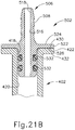
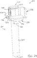
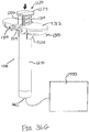
- Syringe (602) of the present example comprises barrel (608) having a distal end (610) and a proximal end (612)).
- Distal end (610) includes a first, dispensing opening (614) and a threaded portion (616) that enables coupling of the syringe (602) to a needle, tubing, etc.
- threaded portion (616) comprises a conventional luer fitting.
- Proximal end (612) includes a second opening (618) that is configured to receive tubular member (640).
- Lumen (620) extends between first and second openings (614, 618).
- Proximal end (612) of syringe barrel (608) further comprises a flange (622), which extends radially outwardly relative to a longitudinal axis (624) of syringe (602) and acts as a finger grip when a user holds syringe (602).
- flange (622) is generally hexagonally shaped in the present example, though it should be understood that any other suitable shape may be used.
- Flange (622) further includes a proximal side (630) facing away from barrel (608) and a distal side (632) facing toward barrel (608).
- Tubular member (640) is configured to receive a plunger assembly, such as plunger assembly (406), in order to draw fluid into lumen (650) of tubular member (640) and prime syringe (602). Similar to syringe (402), plunger assembly (406) may be used to dispense fluid from syringe (606). Alternatively, plunger assembly (406) may be decoupled, leaving a piston, such as piston (434), within lumen (450) so that piston (434) may be advanced and retracted via fluid pressure, in the manner discussed above with respect to syringe (402).
- a plunger assembly such as plunger assembly (406
- plunger assembly (406) may be used to dispense fluid from syringe (606).
- plunger assembly (406) may be decoupled, leaving a piston, such as piston (434), within lumen (450) so that piston (434) may be advanced and retracted via fluid pressure, in the manner discussed above with respect to syringe (402).
- annular recesses (714) each receive sealing elements, which in the present example include an O-ring (750) received in each of the annular recesses (714).
- Tubular portion (710) is sized and configured to be received in second opening (648) of tubular member (640) once, for example, the plunger rod (not shown) is decoupled from the piston (not shown).
- O-rings (750) are configured to provide a fluid tight seal between lumen (650) of tubular member (640) and syringe adapter (702) to prevent the escape of fluid pressure from second end (648) of tubular member (640).
- proximal tubular portion (706) of syringe adapter (702) may be coupled to a source of pressurized fluid medium and distal tubular portion (710) of syringe adapter (702) may be received in second end (648) of tubular member (640). Therefore, a pressurized fluid medium may be communicated to lumen (650) of tubular member (640) via adapter (702) and cause the advancement or retraction of the piston (not shown) within tubular member (640) to cause fluid to be dispensed from or drawn into tubular member (640), respectively.
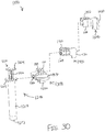
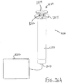
- first spacer (1300) When first spacer (1300) is coupled with barrel (1210), the fit between channel (1340) and flange (1214) prevents relative longitudinal movement between first spacer (1300) and barrel (1210).
- upper sleeve (1310) extends upwardly relative to flange (1214); while lower sleeve (1320) partially encompasses barrel (1210).
- lower sleeve (1320) provides a snug fit about barrel (1210) such that first spacer (1300) releasably grips onto barrel (1210).
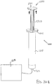
- a small gap (g 1 ) is defined between upper ledge (1412) of second spacer (1400) and the underside of thumb flange (1224). This gap (g 1 ) corresponds to the distance between upper ledges (1412, 1512) when spacers (1400, 1500) are coupled together.
- port (1212) is also coupled with instrument (1000).
- instrument (1000) may be configured and operable just like instrument (10, 2010) described above. Alternatively, instrument (1000) may take any other suitable form. It should also be understood that port (1212) may be coupled with instrument (1000) via flexible tubing and/or using any other suitable structures or techniques.
Landscapes
- Health & Medical Sciences (AREA)
- Life Sciences & Earth Sciences (AREA)
- Engineering & Computer Science (AREA)
- Biomedical Technology (AREA)
- Heart & Thoracic Surgery (AREA)
- Vascular Medicine (AREA)
- Animal Behavior & Ethology (AREA)
- General Health & Medical Sciences (AREA)
- Public Health (AREA)
- Veterinary Medicine (AREA)
- Anesthesiology (AREA)
- Hematology (AREA)
- Ophthalmology & Optometry (AREA)
- Infusion, Injection, And Reservoir Apparatuses (AREA)
Applications Claiming Priority (6)
| Application Number | Priority Date | Filing Date | Title |
|---|---|---|---|
| US201462052074P | 2014-09-18 | 2014-09-18 | |
| US201462052059P | 2014-09-18 | 2014-09-18 | |
| US201462052043P | 2014-09-18 | 2014-09-18 | |
| US201462052038P | 2014-09-18 | 2014-09-18 | |
| US14/843,350 US10258502B2 (en) | 2014-09-18 | 2015-09-02 | Therapeutic agent delivery device |
| PCT/US2015/050394 WO2016044404A2 (en) | 2014-09-18 | 2015-09-16 | Therapeutic agent delivery device |
Publications (2)
| Publication Number | Publication Date |
|---|---|
| EP3193987A2 EP3193987A2 (en) | 2017-07-26 |
| EP3193987B1 true EP3193987B1 (en) | 2020-02-26 |
Family
ID=55524718
Family Applications (1)
| Application Number | Title | Priority Date | Filing Date |
|---|---|---|---|
| EP15808291.7A Active EP3193987B1 (en) | 2014-09-18 | 2015-09-16 | Therapeutic agent delivery device |
Country Status (14)
Families Citing this family (36)
| Publication number | Priority date | Publication date | Assignee | Title |
|---|---|---|---|---|
| ES3013632T3 (en) | 2014-02-12 | 2025-04-14 | Genentech Inc | Apparatus for suprachoroidal administration of therapeutic agent |
| US10258502B2 (en) | 2014-09-18 | 2019-04-16 | Orbit Biomedical Limited | Therapeutic agent delivery device |
| US11090441B2 (en) | 2015-08-24 | 2021-08-17 | Teleflex Medical Incorporated | Dose divider syringe |
| US10478553B2 (en) | 2016-03-09 | 2019-11-19 | Orbit Biomedical Limited | Apparatus for subretinal administration of therapeutic agent via a curved needle |
| AU2017246114B2 (en) * | 2016-04-08 | 2022-03-17 | Allergan, Inc. | Aspiration and injection device |
| US10646374B2 (en) | 2016-06-17 | 2020-05-12 | Orbit Biomedical Limited | Apparatus and method to form entry bleb for subretinal delivery of therapeutic agent |
| US10806629B2 (en) | 2016-06-17 | 2020-10-20 | Gyroscope Therapeutics Limited | Injection device for subretinal delivery of therapeutic agent |
| US11000410B2 (en) | 2016-06-17 | 2021-05-11 | Gyroscope Therapeutics Limited | Guide apparatus for tangential entry into suprachoroidal space |
| US11273072B2 (en) | 2017-01-13 | 2022-03-15 | Gyroscope Therapeutics Limited | Suprachoroidal injection device |
| US11076984B2 (en) | 2017-03-13 | 2021-08-03 | Gyroscope Therapeutics Limited | Method of performing subretinal drainage and agent delivery |
| US10463797B2 (en) * | 2017-09-07 | 2019-11-05 | URO-1, Inc. | Incremental syringe |
| US11090438B2 (en) | 2017-10-17 | 2021-08-17 | Bobby Nourani | Slanted syringe handle |
| CA3085354A1 (en) * | 2017-12-29 | 2019-07-04 | Becton, Dickinson And Company | Low cost syringe with durable and disposable components |
| EP3749386A4 (en) * | 2018-02-09 | 2021-10-27 | Icon Bioscience, Inc. | SYSTEMS, KITS AND METHODS FOR LOADING AND DISPENSING A SMALL VOLUME DOSE FROM A SYRINGE |
| CN112312868B (zh) | 2018-04-12 | 2023-12-22 | 新世界医学有限公司 | 用于眼内流体注射的装置和方法 |
| WO2019226454A1 (en) * | 2018-05-22 | 2019-11-28 | Kci Licensing, Inc. | Systems and methods for managing pneumatic pathways in integrated multilayer wound dressings |
| JP2021531920A (ja) * | 2018-08-02 | 2021-11-25 | バード・ペリフェラル・バスキュラー・インコーポレーテッド | 低傷性の外装を有する植え込み可能なポート配置システム |
| US11759355B1 (en) | 2019-02-26 | 2023-09-19 | Gyroscope Therapeutics Limited | Method of delivering leading blebs and agent to subretinal space |
| JP7455962B2 (ja) * | 2019-10-11 | 2024-03-26 | ジャイロスコープ・セラピューティクス・リミテッド | シリンジのための投薬クリップ組立体 |
| USD987818S1 (en) | 2019-12-04 | 2023-05-30 | Bobby Nourani | Syringe adaptor |
| CN115209931B (zh) * | 2020-03-17 | 2025-05-13 | 美国安进公司 | 受控式分配注射器 |
| EP4098298B1 (en) * | 2020-03-24 | 2025-08-27 | TERUMO Kabushiki Kaisha | Syringe-barrel grip, barrel assembly, and syringe |
| USD960359S1 (en) | 2020-06-19 | 2022-08-09 | Bobby Nourani | Syringe handle |
| EP3967341B1 (en) * | 2020-09-10 | 2025-07-09 | Fenwal, Inc. | Syringe with syringe closure |
| USD987819S1 (en) | 2021-02-18 | 2023-05-30 | Bobby Nourani | Syringe holder |
| DE102021112962A1 (de) * | 2021-05-19 | 2022-11-24 | F+K Innovationen Gmbh & Co. Kg | BI-Dose-Vorrichtung |
| WO2023001244A1 (zh) | 2021-07-22 | 2023-01-26 | 成都弘基生物科技有限公司 | 一种眼用注射组件、注射装置及使用方法 |
| US20230125693A1 (en) * | 2021-10-22 | 2023-04-27 | Lisa Monique Staples | Breathing circuit-to-laryngoscope adapter |
| WO2023172585A1 (en) * | 2022-03-07 | 2023-09-14 | The Johns Hopkins University | Method and system for delivery of therapeutics to eye |
| EP4554534A1 (en) | 2022-07-11 | 2025-05-21 | Genentech, Inc. | Transvitreal subretinal injector |
| IL319330A (en) | 2022-09-06 | 2025-05-01 | Genentech Inc | A device for subretinal administration of a therapeutic agent using a double curved needle |
| EP4648726A2 (en) | 2023-01-13 | 2025-11-19 | Genentech, Inc. | Dose dock for syringe |
| WO2025072590A1 (en) | 2023-09-29 | 2025-04-03 | Genentech, Inc. | Ocular cannula guide, applicator, and marking instrument |
| WO2025207699A1 (en) | 2024-03-27 | 2025-10-02 | Genentech, Inc. | Torque ring for subretinal injection device |
| WO2025217214A2 (en) | 2024-04-08 | 2025-10-16 | Regenxbio Inc. | Recombinant adeno-associated viruses and uses thereof |
| WO2025217230A1 (en) | 2024-04-08 | 2025-10-16 | Regenxbio Inc. | Vectorized anti-complement antibodies and complement agents and administration thereof |
Family Cites Families (113)
| Publication number | Priority date | Publication date | Assignee | Title |
|---|---|---|---|---|
| US287576A (en) * | 1883-10-30 | Sewing machine | ||
| US2875761A (en) | 1956-10-01 | 1959-03-03 | Norman D Helmer | Multiple dosage syringe |
| US4267846A (en) * | 1979-01-29 | 1981-05-19 | Critikon, Inc. | Controlled volume blood sampling syringe |
| US4231494A (en) * | 1979-03-22 | 1980-11-04 | Greenwood David L | Syringe adaptor assembly |
| US4874385A (en) * | 1987-12-16 | 1989-10-17 | Sherwood Medical Company | Plunger lock device |
| US5066276A (en) * | 1988-06-21 | 1991-11-19 | Alcon Laboratories, Inc. | Method and apparatus for injecting viscous fluid into the eye to lift pre-retinal and post-retinal membrane with linear pressure control |
| US5019037A (en) * | 1989-07-06 | 1991-05-28 | Alcon Laboratories, Inc. | Pneumatic retinopexy injector |
| US5817075A (en) * | 1989-08-14 | 1998-10-06 | Photogenesis, Inc. | Method for preparation and transplantation of planar implants and surgical instrument therefor |
| US5273530A (en) | 1990-11-14 | 1993-12-28 | The University Of Rochester | Intraretinal delivery and withdrawal instruments |
| US5252064A (en) * | 1991-02-19 | 1993-10-12 | Teledyne Industries, Inc. | Subgingival irrigator |
| US5601077A (en) * | 1991-08-07 | 1997-02-11 | Becton, Dickinson And Company | Nasal syringe sprayer with removable dose limiting structure |
| US5653715A (en) | 1993-03-09 | 1997-08-05 | Chiron Vision Corporation | Apparatus for preparing an intraocular lens for insertion |
| US5803918A (en) * | 1993-05-06 | 1998-09-08 | Becton Dickinson And Company | Syringe for medicinal purposes |
| DE4339528C2 (de) * | 1993-11-19 | 1995-09-07 | Freudenberg Carl Fa | Einwegspritze |
| JP3306796B2 (ja) * | 1995-01-26 | 2002-07-24 | 大成化工株式会社 | 薬液が予備充填された注入筒向けガラスカートリッジ |
| US5964740A (en) | 1996-07-09 | 1999-10-12 | Asahi Kogaku Kogyo Kabushiki Kaisha | Treatment accessory for an endoscope |
| US6283951B1 (en) | 1996-10-11 | 2001-09-04 | Transvascular, Inc. | Systems and methods for delivering drugs to selected locations within the body |
| IL124038A (en) | 1995-10-13 | 2004-02-19 | Transvascular Inc | Apparatus for bypassing arterial obstructions and/or performing other transvascular procedures |
| US5887764A (en) * | 1996-11-27 | 1999-03-30 | Ennis, Iii; James F. | Apparatus for a pressurized injector |
| US5975355A (en) * | 1997-06-25 | 1999-11-02 | Cecala; Ann | Dosage unit measurer for syringe |
| DE19741487C2 (de) | 1997-09-19 | 2000-08-31 | Univ Eberhard Karls | Vorrichtung für einen Zugang in den Subretinalraum eines Auges |
| US6200289B1 (en) | 1998-04-10 | 2001-03-13 | Milestone Scientific, Inc. | Pressure/force computer controlled drug delivery system and the like |
| US6309374B1 (en) * | 1998-08-03 | 2001-10-30 | Insite Vision Incorporated | Injection apparatus and method of using same |
| US6143004A (en) | 1998-08-18 | 2000-11-07 | Atrion Medical Products, Inc. | Suturing device |
| US6162197A (en) | 1998-12-22 | 2000-12-19 | Mohammad; Owais | Retractable needle assembly and method of making the same |
| JP3372886B2 (ja) | 1999-02-18 | 2003-02-04 | エスエムシー株式会社 | 管継手 |
| US6368315B1 (en) | 1999-06-23 | 2002-04-09 | Durect Corporation | Composite drug delivery catheter |
| EP1092447B1 (en) | 1999-10-14 | 2004-01-07 | Becton Dickinson and Company | Nasal delivery device including spray nozzle |
| ES2240180T3 (es) | 1999-10-21 | 2005-10-16 | Alcon Inc. | Administracion sub-tenon de medicamentos. |
| US7357794B2 (en) | 2002-01-17 | 2008-04-15 | Medtronic Vascular, Inc. | Devices, systems and methods for acute or chronic delivery of substances or apparatus to extravascular treatment sites |
| US6989004B2 (en) | 2001-02-28 | 2006-01-24 | Rex Medical, L.P. | Apparatus for delivering ablation fluid to treat lesions |
| US7122042B2 (en) | 2001-03-15 | 2006-10-17 | Lorusso Frank J | Apparatuses and methods for transcleral cautery and subretinal drainage |
| US7431710B2 (en) | 2002-04-08 | 2008-10-07 | Glaukos Corporation | Ocular implants with anchors and methods thereof |
| US6494863B1 (en) | 2001-10-15 | 2002-12-17 | Retractable Technologies, Inc. | One-use retracting syringe with positive needle retention |
| JP2005517468A (ja) | 2002-02-14 | 2005-06-16 | フォトジェネシス インコーポレイテッド | 網膜下移植装置および同装置と共に使用されるカニューレ |
| US7316676B2 (en) | 2002-08-20 | 2008-01-08 | Gholam A. Peyman | Treatment of retinal detachment |
| WO2004028477A2 (en) | 2002-09-29 | 2004-04-08 | Surmodics, Inc. | Methods for treatment and/or prevention of retinal disease |
| US6997904B2 (en) * | 2002-12-24 | 2006-02-14 | Robert David Sculati | Viscous fluid injection system |
| KR100473568B1 (ko) * | 2003-01-25 | 2005-03-10 | 이희영 | 밀폐형 지방이식 시스템 |
| US7329241B2 (en) | 2003-02-14 | 2008-02-12 | Valeant Pharmaceuticals North America | Drug delivery system for administering an adjustable preset dose |
| US7220224B1 (en) * | 2003-03-07 | 2007-05-22 | Minu, Llc | Retinal translocation and fixation using adhesive material |
| US20040199130A1 (en) | 2003-04-03 | 2004-10-07 | Chornenky Victor I. | Apparatus and method for treatment of macular degeneration |
| JP4289919B2 (ja) | 2003-05-06 | 2009-07-01 | 朝日インテック株式会社 | 薬液注入装置 |
| DE10326706A1 (de) * | 2003-06-04 | 2005-01-05 | Schott Ag | Spritze, insbesondere für medizinische Anwendungen, sowie Verfahren zum Herstellen einer solchen |
| PL1641914T3 (pl) | 2003-06-27 | 2017-01-31 | DePuy Synthes Products, Inc. | Komórki pochodzące z poporodowej tkanki łożyska oraz sposoby uzyskiwania i zastosowania tych komórek |
| FR2858931B1 (fr) * | 2003-08-21 | 2007-04-13 | Becton Dickinson France | Dispositif d'administration orale d'un medicament |
| AR042539A1 (es) * | 2003-12-18 | 2005-06-22 | Jose Santiago Rolla | Unidad para suministro de inyectables en forma manual o automatica |
| PL1715827T3 (pl) | 2004-01-23 | 2011-07-29 | Iscience Interventional Corp | Złożona okulistyczna mikrokaniula |
| US8235256B2 (en) * | 2004-02-12 | 2012-08-07 | Kyphon Sarl | Manual pump mechanism and delivery system |
| US7563222B2 (en) * | 2004-02-12 | 2009-07-21 | Neovista, Inc. | Methods and apparatus for intraocular brachytherapy |
| US20100173866A1 (en) * | 2004-04-29 | 2010-07-08 | Iscience Interventional Corporation | Apparatus and method for ocular treatment |
| US20080058704A1 (en) | 2004-04-29 | 2008-03-06 | Michael Hee | Apparatus and Method for Ocular Treatment |
| US7601140B2 (en) * | 2004-06-25 | 2009-10-13 | Alcon, Inc. | Syringe pressure applicator |
| JP2006010010A (ja) | 2004-06-29 | 2006-01-12 | Smc Corp | 管継手 |
| US20060047250A1 (en) | 2004-08-30 | 2006-03-02 | Hickingbotham Dyson W | Fluid delivery device |
| US20060173415A1 (en) | 2005-01-11 | 2006-08-03 | Christy Cummins | Syringe adaptor |
| US7686788B2 (en) * | 2005-03-03 | 2010-03-30 | Boston Scientific Scimed, Inc. | Catheter having a distal drug delivery unit and method of using same |
| DK1911480T3 (da) * | 2005-05-02 | 2009-12-07 | Elastomeric Systems S L | Spröjte til indgift af flere doser og omfattende en injektionsnål med sterilitetsbeskyttelse |
| US8465451B2 (en) | 2005-06-22 | 2013-06-18 | Covidien Lp | Methods and apparatus for introducing tumescent fluid to body tissue |
| US9144645B2 (en) * | 2005-09-21 | 2015-09-29 | Applied Diabetes Research, Inc. | One piece sealing reservoir for an insulin infusion pump |
| US20070202186A1 (en) | 2006-02-22 | 2007-08-30 | Iscience Interventional Corporation | Apparatus and formulations for suprachoroidal drug delivery |
| US8197435B2 (en) | 2006-05-02 | 2012-06-12 | Emory University | Methods and devices for drug delivery to ocular tissue using microneedle |
| US20080004596A1 (en) | 2006-05-25 | 2008-01-03 | Palo Alto Institute | Delivery of agents by microneedle catheter |
| CN101466614B (zh) * | 2006-06-13 | 2013-05-01 | 诺信公司 | 液体分配注射器 |
| US20080281292A1 (en) | 2006-10-16 | 2008-11-13 | Hickingbotham Dyson W | Retractable Injection Port |
| US20090124996A1 (en) * | 2006-11-03 | 2009-05-14 | Scott Heneveld | Apparatus and methods for injecting high viscosity dermal fillers |
| US20080161845A1 (en) | 2006-11-16 | 2008-07-03 | Mani, Inc. | Trocar |
| US20090018548A1 (en) * | 2007-07-13 | 2009-01-15 | Charles Steven T | Pneumatically-Powered Intraocular Lens Injection Device with Removable Cartridge |
| US20090018512A1 (en) * | 2007-07-13 | 2009-01-15 | Charles Steven T | Pneumatically-Powered Ophthalmic Injector |
| US20110207987A1 (en) | 2009-11-02 | 2011-08-25 | Salutaris Medical Devices, Inc. | Methods And Devices For Delivering Appropriate Minimally-Invasive Extraocular Radiation |
| EP2227257B1 (en) | 2008-01-07 | 2013-06-26 | Salutaris Medical Devices, Inc. | Devices for minimally-invasive extraocular delivery of radiation to the posterior portion of the eye |
| US20100305514A1 (en) | 2008-01-10 | 2010-12-02 | Bausch & Lomb Incorporated | Intravitreal injection system having coaxial cannulae and use thereof |
| US20100081707A1 (en) * | 2008-02-21 | 2010-04-01 | Ali Robin R | Devices and methods for delivering polynucleotides into retinal cells of the macula and fovea |
| US7976510B2 (en) * | 2008-02-28 | 2011-07-12 | Becton, Dickinson And Company | Syringe with adjustable two piece plunger rod |
| CA2717441A1 (en) * | 2008-03-05 | 2009-09-11 | Ivantis, Inc. | Methods and apparatus for treating glaucoma |
| JP2012500049A (ja) | 2008-08-13 | 2012-01-05 | シルク・ロード・メディカル・インコーポレイテッド | 縫合糸送達デバイス |
| US8425473B2 (en) | 2009-01-23 | 2013-04-23 | Iscience Interventional Corporation | Subretinal access device |
| BRPI1010657A2 (pt) | 2009-05-15 | 2017-07-18 | Iscience Interventional Corp | dispositivo para acessar o espaço sub-rentinal de um olho , introduzir de haste tubular , dispositivo de cânula, e , método para cateterizar o espaço sub-retinal adjacente à mácula de um olho |
| WO2010141837A1 (en) | 2009-06-05 | 2010-12-09 | Vance Products Incorporated, D/B/A/ Cook Urological Incorporated | Access sheath and needle assembly for delivering therapeutic material |
| US20110087173A1 (en) * | 2009-10-12 | 2011-04-14 | Sibbitt Jr Wilmer L | Automatic syringes |
| CH702815A1 (de) * | 2010-03-10 | 2011-09-15 | Medmix Systems Ag | Befüllvorrichtung zum Befüllen mindestens eines ersten Reservoirs eines Applikators. |
| SE535983C2 (sv) * | 2010-04-20 | 2013-03-19 | Noviscens Ab | Spruta |
| US9526841B2 (en) * | 2010-06-30 | 2016-12-27 | Nipro Corporation | Spraying device |
| CA2813060C (en) * | 2010-10-01 | 2017-02-21 | Bracco Imaging S.P.A. | Finger-grip device for medical syringe or cartridge |
| JP5996544B2 (ja) | 2010-10-15 | 2016-09-21 | クリアサイド・バイオメディカル・インコーポレーテッドClearside Biomedical Incorporated | 眼球アクセス用装置 |
| KR101978235B1 (ko) * | 2011-04-25 | 2019-05-15 | 아이콘 바이오사이언스, 인크. | 주사기용 투여량 가이드 |
| AU2012250060B2 (en) | 2011-04-28 | 2016-12-15 | Biogen Ma Inc. | A limiter for a dispensing device |
| JP5695485B2 (ja) * | 2011-04-28 | 2015-04-08 | 株式会社吉野工業所 | 注射器 |
| WO2012157582A1 (ja) * | 2011-05-13 | 2012-11-22 | ニプロ株式会社 | 鼻腔投与容器 |
| US8852165B2 (en) | 2011-06-16 | 2014-10-07 | II Edward G. Mackay | Endoluminal drug delivery devices and methods |
| US9629675B2 (en) | 2011-10-19 | 2017-04-25 | Confluent Medical Technologies, Inc. | Tissue treatment device and related methods |
| US20130131633A1 (en) * | 2011-11-18 | 2013-05-23 | Allergan, Inc. | Modular injection system and method for diluting an injectable fluid |
| JP6039190B2 (ja) * | 2012-02-13 | 2016-12-07 | 株式会社ニデック | 医療用器具 |
| WO2013123309A1 (en) | 2012-02-15 | 2013-08-22 | The Cleveland Clinic Foundation | Catheter assembly and method of treating a vascular disease |
| CA2882184C (en) | 2012-08-27 | 2021-09-07 | Clearside Biomedical, Inc. | Apparatus and methods for drug delivery using microneedles |
| US9132229B2 (en) * | 2012-09-13 | 2015-09-15 | Alcon Research, Ltd. | System and method of priming a surgical cassette |
| US9301795B2 (en) | 2012-10-29 | 2016-04-05 | Ablative Solutions, Inc. | Transvascular catheter for extravascular delivery |
| BR112015010566A2 (pt) | 2012-11-08 | 2017-07-11 | Clearside Biomedical Inc | métodos e dispositivos para o tratamento de doenças oculares em indivíduos humanos |
| EP2732770B1 (de) | 2012-11-16 | 2016-08-24 | Erbe Elektromedizin GmbH | Nadellose Injektionsvorrichtung |
| WO2014110624A1 (en) * | 2013-01-15 | 2014-07-24 | Heriot Wilson J | Method and device for treating retinal detachment |
| WO2014153085A1 (en) * | 2013-03-14 | 2014-09-25 | Gavis Pharmaceuticals, Llc | Syringe |
| US20160143776A1 (en) | 2013-08-02 | 2016-05-26 | Tel Hashomer Medical Research Infrastructure And Services Ltd. | A device for delivery of compositions to the eye |
| US9795503B2 (en) * | 2013-10-18 | 2017-10-24 | Rodolfo Alfredo PEREZ GROSSMANN | Method and apparatus for trabeculectomy and suprachoroidal shunt surgery |
| ES3013632T3 (en) | 2014-02-12 | 2025-04-14 | Genentech Inc | Apparatus for suprachoroidal administration of therapeutic agent |
| US9925088B2 (en) | 2014-06-06 | 2018-03-27 | Janssen Biotech, Inc. | Sub-retinal tangential needle catheter guide and introducer |
| US9949874B2 (en) * | 2014-06-06 | 2018-04-24 | Janssen Biotech, Inc. | Therapeutic agent delivery device with convergent lumen |
| MX2016016836A (es) | 2014-06-17 | 2017-07-27 | Clearside Biomedical Inc | Metodos y dispositivos para tratar trastornos oculares posteriores. |
| RU2710491C2 (ru) | 2014-06-20 | 2019-12-26 | Клиасайд Байомедикал, Инк. | Устройство для инъекции лекарственного средства в глазную ткань и способ инъекции лекарственного средства в глазную ткань |
| US10064752B2 (en) | 2014-09-11 | 2018-09-04 | Orbit Biomedical Limited | Motorized suprachoroidal injection of therapeutic agent |
| US10219936B2 (en) | 2014-09-11 | 2019-03-05 | Orbit Biomedical Limited | Therapeutic agent delivery device with advanceable cannula and needle |
| US10322028B2 (en) | 2014-09-11 | 2019-06-18 | Orbit Biomedical Limited | Method and apparatus for sensing position between layers of an eye |
| US10258502B2 (en) | 2014-09-18 | 2019-04-16 | Orbit Biomedical Limited | Therapeutic agent delivery device |
| GB201516066D0 (en) | 2015-09-10 | 2015-10-28 | Young & Co Llp D | Treatment of retinitis pigmentosa |
-
2015
- 2015-09-02 US US14/843,350 patent/US10258502B2/en active Active
- 2015-09-16 KR KR1020177010206A patent/KR102202183B1/ko active Active
- 2015-09-16 BR BR112017005332-2A patent/BR112017005332B1/pt active IP Right Grant
- 2015-09-16 AU AU2015317872A patent/AU2015317872B2/en active Active
- 2015-09-16 CN CN201580062516.1A patent/CN107223042B/zh active Active
- 2015-09-16 RU RU2017113086A patent/RU2704596C2/ru active
- 2015-09-16 MX MX2017003616A patent/MX2017003616A/es unknown
- 2015-09-16 SG SG11201702095XA patent/SG11201702095XA/en unknown
- 2015-09-16 WO PCT/US2015/050394 patent/WO2016044404A2/en not_active Ceased
- 2015-09-16 JP JP2017515083A patent/JP6772127B2/ja active Active
- 2015-09-16 CA CA2961529A patent/CA2961529C/en active Active
- 2015-09-16 EP EP15808291.7A patent/EP3193987B1/en active Active
-
2017
- 2017-03-16 PH PH12017500502A patent/PH12017500502A1/en unknown
- 2017-04-12 ZA ZA2017/02634A patent/ZA201702634B/en unknown
-
2019
- 2019-02-25 US US16/284,185 patent/US11337852B2/en active Active
-
2020
- 2020-05-11 JP JP2020083145A patent/JP6953580B2/ja active Active
Non-Patent Citations (1)
| Title |
|---|
| None * |
Also Published As
| Publication number | Publication date |
|---|---|
| US20160081849A1 (en) | 2016-03-24 |
| BR112017005332B1 (pt) | 2022-04-12 |
| JP6772127B2 (ja) | 2020-10-21 |
| JP2020121196A (ja) | 2020-08-13 |
| BR112017005332A2 (pt) | 2017-12-12 |
| JP6953580B2 (ja) | 2021-10-27 |
| US11337852B2 (en) | 2022-05-24 |
| MX2017003616A (es) | 2018-01-24 |
| WO2016044404A2 (en) | 2016-03-24 |
| CA2961529A1 (en) | 2016-03-24 |
| WO2016044404A3 (en) | 2016-06-09 |
| CN107223042B (zh) | 2020-02-21 |
| KR102202183B1 (ko) | 2021-01-13 |
| EP3193987A2 (en) | 2017-07-26 |
| ZA201702634B (en) | 2019-06-26 |
| RU2704596C2 (ru) | 2019-10-29 |
| US20190183674A1 (en) | 2019-06-20 |
| KR20170056645A (ko) | 2017-05-23 |
| CA2961529C (en) | 2021-08-31 |
| AU2015317872A1 (en) | 2017-04-06 |
| PH12017500502A1 (en) | 2017-08-30 |
| AU2015317872B2 (en) | 2019-12-19 |
| SG11201702095XA (en) | 2017-04-27 |
| US10258502B2 (en) | 2019-04-16 |
| RU2017113086A (ru) | 2018-10-18 |
| JP2017527406A (ja) | 2017-09-21 |
| RU2017113086A3 (cg-RX-API-DMAC7.html) | 2019-06-14 |
| CN107223042A (zh) | 2017-09-29 |
Similar Documents
| Publication | Publication Date | Title |
|---|---|---|
| EP3193987B1 (en) | Therapeutic agent delivery device | |
| US20250318953A1 (en) | Therapeutic agent delivery device with convergent lumen | |
| US11723798B2 (en) | Sub-retinal tangential needle catheter guide and introducer | |
| EP3191031B1 (en) | Therapeutic agent delivery device with advanceable cannula and needle | |
| JP7023873B2 (ja) | 湾曲した針を介する治療剤の網膜下投与のための装置 | |
| HK40062697B (zh) | 用於治疗剂的脉络膜上施用的方法和设备 | |
| HK40014920B (zh) | 用於治疗剂的脉络膜上施用的方法和设备 | |
| HK40047835B (en) | Apparatus for suprachoroidal administration of therapeutic agent |
Legal Events
| Date | Code | Title | Description |
|---|---|---|---|
| STAA | Information on the status of an ep patent application or granted ep patent |
Free format text: STATUS: THE INTERNATIONAL PUBLICATION HAS BEEN MADE |
|
| PUAI | Public reference made under article 153(3) epc to a published international application that has entered the european phase |
Free format text: ORIGINAL CODE: 0009012 |
|
| STAA | Information on the status of an ep patent application or granted ep patent |
Free format text: STATUS: REQUEST FOR EXAMINATION WAS MADE |
|
| 17P | Request for examination filed |
Effective date: 20170418 |
|
| AK | Designated contracting states |
Kind code of ref document: A2 Designated state(s): AL AT BE BG CH CY CZ DE DK EE ES FI FR GB GR HR HU IE IS IT LI LT LU LV MC MK MT NL NO PL PT RO RS SE SI SK SM TR |
|
| AX | Request for extension of the european patent |
Extension state: BA ME |
|
| STAA | Information on the status of an ep patent application or granted ep patent |
Free format text: STATUS: EXAMINATION IS IN PROGRESS |
|
| 17Q | First examination report despatched |
Effective date: 20180918 |
|
| RAP1 | Party data changed (applicant data changed or rights of an application transferred) |
Owner name: ORBIT BIOMEDICAL LIMITED |
|
| GRAP | Despatch of communication of intention to grant a patent |
Free format text: ORIGINAL CODE: EPIDOSNIGR1 |
|
| STAA | Information on the status of an ep patent application or granted ep patent |
Free format text: STATUS: GRANT OF PATENT IS INTENDED |
|
| INTG | Intention to grant announced |
Effective date: 20190729 |
|
| GRAS | Grant fee paid |
Free format text: ORIGINAL CODE: EPIDOSNIGR3 |
|
| GRAJ | Information related to disapproval of communication of intention to grant by the applicant or resumption of examination proceedings by the epo deleted |
Free format text: ORIGINAL CODE: EPIDOSDIGR1 |
|
| GRAL | Information related to payment of fee for publishing/printing deleted |
Free format text: ORIGINAL CODE: EPIDOSDIGR3 |
|
| STAA | Information on the status of an ep patent application or granted ep patent |
Free format text: STATUS: EXAMINATION IS IN PROGRESS |
|
| INTC | Intention to grant announced (deleted) | ||
| GRAR | Information related to intention to grant a patent recorded |
Free format text: ORIGINAL CODE: EPIDOSNIGR71 |
|
| STAA | Information on the status of an ep patent application or granted ep patent |
Free format text: STATUS: GRANT OF PATENT IS INTENDED |
|
| GRAA | (expected) grant |
Free format text: ORIGINAL CODE: 0009210 |
|
| STAA | Information on the status of an ep patent application or granted ep patent |
Free format text: STATUS: THE PATENT HAS BEEN GRANTED |
|
| AK | Designated contracting states |
Kind code of ref document: B1 Designated state(s): AL AT BE BG CH CY CZ DE DK EE ES FI FR GB GR HR HU IE IS IT LI LT LU LV MC MK MT NL NO PL PT RO RS SE SI SK SM TR |
|
| AX | Request for extension of the european patent |
Extension state: BA ME |
|
| INTG | Intention to grant announced |
Effective date: 20200120 |
|
| REG | Reference to a national code |
Ref country code: GB Ref legal event code: FG4D |
|
| REG | Reference to a national code |
Ref country code: CH Ref legal event code: EP |
|
| REG | Reference to a national code |
Ref country code: AT Ref legal event code: REF Ref document number: 1236875 Country of ref document: AT Kind code of ref document: T Effective date: 20200315 |
|
| REG | Reference to a national code |
Ref country code: IE Ref legal event code: FG4D |
|
| REG | Reference to a national code |
Ref country code: DE Ref legal event code: R096 Ref document number: 602015047820 Country of ref document: DE |
|
| PG25 | Lapsed in a contracting state [announced via postgrant information from national office to epo] |
Ref country code: FI Free format text: LAPSE BECAUSE OF FAILURE TO SUBMIT A TRANSLATION OF THE DESCRIPTION OR TO PAY THE FEE WITHIN THE PRESCRIBED TIME-LIMIT Effective date: 20200226 Ref country code: NO Free format text: LAPSE BECAUSE OF FAILURE TO SUBMIT A TRANSLATION OF THE DESCRIPTION OR TO PAY THE FEE WITHIN THE PRESCRIBED TIME-LIMIT Effective date: 20200526 Ref country code: RS Free format text: LAPSE BECAUSE OF FAILURE TO SUBMIT A TRANSLATION OF THE DESCRIPTION OR TO PAY THE FEE WITHIN THE PRESCRIBED TIME-LIMIT Effective date: 20200226 |
|
| REG | Reference to a national code |
Ref country code: NL Ref legal event code: MP Effective date: 20200226 |
|
| REG | Reference to a national code |
Ref country code: LT Ref legal event code: MG4D |
|
| PG25 | Lapsed in a contracting state [announced via postgrant information from national office to epo] |
Ref country code: LV Free format text: LAPSE BECAUSE OF FAILURE TO SUBMIT A TRANSLATION OF THE DESCRIPTION OR TO PAY THE FEE WITHIN THE PRESCRIBED TIME-LIMIT Effective date: 20200226 Ref country code: SE Free format text: LAPSE BECAUSE OF FAILURE TO SUBMIT A TRANSLATION OF THE DESCRIPTION OR TO PAY THE FEE WITHIN THE PRESCRIBED TIME-LIMIT Effective date: 20200226 Ref country code: IS Free format text: LAPSE BECAUSE OF FAILURE TO SUBMIT A TRANSLATION OF THE DESCRIPTION OR TO PAY THE FEE WITHIN THE PRESCRIBED TIME-LIMIT Effective date: 20200626 Ref country code: HR Free format text: LAPSE BECAUSE OF FAILURE TO SUBMIT A TRANSLATION OF THE DESCRIPTION OR TO PAY THE FEE WITHIN THE PRESCRIBED TIME-LIMIT Effective date: 20200226 Ref country code: GR Free format text: LAPSE BECAUSE OF FAILURE TO SUBMIT A TRANSLATION OF THE DESCRIPTION OR TO PAY THE FEE WITHIN THE PRESCRIBED TIME-LIMIT Effective date: 20200527 Ref country code: BG Free format text: LAPSE BECAUSE OF FAILURE TO SUBMIT A TRANSLATION OF THE DESCRIPTION OR TO PAY THE FEE WITHIN THE PRESCRIBED TIME-LIMIT Effective date: 20200526 |
|
| PG25 | Lapsed in a contracting state [announced via postgrant information from national office to epo] |
Ref country code: NL Free format text: LAPSE BECAUSE OF FAILURE TO SUBMIT A TRANSLATION OF THE DESCRIPTION OR TO PAY THE FEE WITHIN THE PRESCRIBED TIME-LIMIT Effective date: 20200226 |
|
| REG | Reference to a national code |
Ref country code: DE Ref legal event code: R082 Ref document number: 602015047820 Country of ref document: DE Representative=s name: MUELLER-BORE & PARTNER PATENTANWAELTE PARTG MB, DE Ref country code: DE Ref legal event code: R081 Ref document number: 602015047820 Country of ref document: DE Owner name: GYROSCOPE THERAPEUTICS LIMITED, GB Free format text: FORMER OWNER: ORBIT BIOMEDICAL LTD., LONDON, GB |
|
| PG25 | Lapsed in a contracting state [announced via postgrant information from national office to epo] |
Ref country code: RO Free format text: LAPSE BECAUSE OF FAILURE TO SUBMIT A TRANSLATION OF THE DESCRIPTION OR TO PAY THE FEE WITHIN THE PRESCRIBED TIME-LIMIT Effective date: 20200226 Ref country code: PT Free format text: LAPSE BECAUSE OF FAILURE TO SUBMIT A TRANSLATION OF THE DESCRIPTION OR TO PAY THE FEE WITHIN THE PRESCRIBED TIME-LIMIT Effective date: 20200719 Ref country code: CZ Free format text: LAPSE BECAUSE OF FAILURE TO SUBMIT A TRANSLATION OF THE DESCRIPTION OR TO PAY THE FEE WITHIN THE PRESCRIBED TIME-LIMIT Effective date: 20200226 Ref country code: ES Free format text: LAPSE BECAUSE OF FAILURE TO SUBMIT A TRANSLATION OF THE DESCRIPTION OR TO PAY THE FEE WITHIN THE PRESCRIBED TIME-LIMIT Effective date: 20200226 Ref country code: LT Free format text: LAPSE BECAUSE OF FAILURE TO SUBMIT A TRANSLATION OF THE DESCRIPTION OR TO PAY THE FEE WITHIN THE PRESCRIBED TIME-LIMIT Effective date: 20200226 Ref country code: SM Free format text: LAPSE BECAUSE OF FAILURE TO SUBMIT A TRANSLATION OF THE DESCRIPTION OR TO PAY THE FEE WITHIN THE PRESCRIBED TIME-LIMIT Effective date: 20200226 Ref country code: EE Free format text: LAPSE BECAUSE OF FAILURE TO SUBMIT A TRANSLATION OF THE DESCRIPTION OR TO PAY THE FEE WITHIN THE PRESCRIBED TIME-LIMIT Effective date: 20200226 Ref country code: SK Free format text: LAPSE BECAUSE OF FAILURE TO SUBMIT A TRANSLATION OF THE DESCRIPTION OR TO PAY THE FEE WITHIN THE PRESCRIBED TIME-LIMIT Effective date: 20200226 Ref country code: DK Free format text: LAPSE BECAUSE OF FAILURE TO SUBMIT A TRANSLATION OF THE DESCRIPTION OR TO PAY THE FEE WITHIN THE PRESCRIBED TIME-LIMIT Effective date: 20200226 |
|
| REG | Reference to a national code |
Ref country code: GB Ref legal event code: 732E Free format text: REGISTERED BETWEEN 20201015 AND 20201021 |
|
| REG | Reference to a national code |
Ref country code: AT Ref legal event code: MK05 Ref document number: 1236875 Country of ref document: AT Kind code of ref document: T Effective date: 20200226 |
|
| REG | Reference to a national code |
Ref country code: DE Ref legal event code: R097 Ref document number: 602015047820 Country of ref document: DE |
|
| PLBE | No opposition filed within time limit |
Free format text: ORIGINAL CODE: 0009261 |
|
| STAA | Information on the status of an ep patent application or granted ep patent |
Free format text: STATUS: NO OPPOSITION FILED WITHIN TIME LIMIT |
|
| PG25 | Lapsed in a contracting state [announced via postgrant information from national office to epo] |
Ref country code: AT Free format text: LAPSE BECAUSE OF FAILURE TO SUBMIT A TRANSLATION OF THE DESCRIPTION OR TO PAY THE FEE WITHIN THE PRESCRIBED TIME-LIMIT Effective date: 20200226 Ref country code: IT Free format text: LAPSE BECAUSE OF FAILURE TO SUBMIT A TRANSLATION OF THE DESCRIPTION OR TO PAY THE FEE WITHIN THE PRESCRIBED TIME-LIMIT Effective date: 20200226 |
|
| 26N | No opposition filed |
Effective date: 20201127 |
|
| PG25 | Lapsed in a contracting state [announced via postgrant information from national office to epo] |
Ref country code: SI Free format text: LAPSE BECAUSE OF FAILURE TO SUBMIT A TRANSLATION OF THE DESCRIPTION OR TO PAY THE FEE WITHIN THE PRESCRIBED TIME-LIMIT Effective date: 20200226 Ref country code: PL Free format text: LAPSE BECAUSE OF FAILURE TO SUBMIT A TRANSLATION OF THE DESCRIPTION OR TO PAY THE FEE WITHIN THE PRESCRIBED TIME-LIMIT Effective date: 20200226 |
|
| PG25 | Lapsed in a contracting state [announced via postgrant information from national office to epo] |
Ref country code: MC Free format text: LAPSE BECAUSE OF FAILURE TO SUBMIT A TRANSLATION OF THE DESCRIPTION OR TO PAY THE FEE WITHIN THE PRESCRIBED TIME-LIMIT Effective date: 20200226 |
|
| REG | Reference to a national code |
Ref country code: CH Ref legal event code: PL |
|
| VS25 | Lapsed in a validation state [announced via postgrant information from nat. office to epo] |
Ref country code: MA Free format text: LAPSE BECAUSE OF FAILURE TO SUBMIT A TRANSLATION OF THE DESCRIPTION OR TO PAY THE FEE WITHIN THE PRESCRIBED TIME-LIMIT Effective date: 20200226 |
|
| REG | Reference to a national code |
Ref country code: BE Ref legal event code: MM Effective date: 20200930 |
|
| PG25 | Lapsed in a contracting state [announced via postgrant information from national office to epo] |
Ref country code: LU Free format text: LAPSE BECAUSE OF NON-PAYMENT OF DUE FEES Effective date: 20200916 |
|
| REG | Reference to a national code |
Ref country code: DE Ref legal event code: R081 Ref document number: 602015047820 Country of ref document: DE Owner name: GENENTECH, INC., SOUTH SAN FRANCISCO, US Free format text: FORMER OWNER: GYROSCOPE THERAPEUTICS LIMITED, STEVENAGE, GB Ref country code: DE Ref legal event code: R081 Ref document number: 602015047820 Country of ref document: DE Owner name: GYROSCOPE THERAPEUTICS LIMITED, GB Free format text: FORMER OWNER: GYROSCOPE THERAPEUTICS LIMITED, STEVENAGE, GB |
|
| PG25 | Lapsed in a contracting state [announced via postgrant information from national office to epo] |
Ref country code: IE Free format text: LAPSE BECAUSE OF NON-PAYMENT OF DUE FEES Effective date: 20200916 Ref country code: LI Free format text: LAPSE BECAUSE OF NON-PAYMENT OF DUE FEES Effective date: 20200930 Ref country code: CH Free format text: LAPSE BECAUSE OF NON-PAYMENT OF DUE FEES Effective date: 20200930 Ref country code: BE Free format text: LAPSE BECAUSE OF NON-PAYMENT OF DUE FEES Effective date: 20200930 |
|
| PG25 | Lapsed in a contracting state [announced via postgrant information from national office to epo] |
Ref country code: TR Free format text: LAPSE BECAUSE OF FAILURE TO SUBMIT A TRANSLATION OF THE DESCRIPTION OR TO PAY THE FEE WITHIN THE PRESCRIBED TIME-LIMIT Effective date: 20200226 Ref country code: MT Free format text: LAPSE BECAUSE OF FAILURE TO SUBMIT A TRANSLATION OF THE DESCRIPTION OR TO PAY THE FEE WITHIN THE PRESCRIBED TIME-LIMIT Effective date: 20200226 Ref country code: CY Free format text: LAPSE BECAUSE OF FAILURE TO SUBMIT A TRANSLATION OF THE DESCRIPTION OR TO PAY THE FEE WITHIN THE PRESCRIBED TIME-LIMIT Effective date: 20200226 |
|
| PG25 | Lapsed in a contracting state [announced via postgrant information from national office to epo] |
Ref country code: MK Free format text: LAPSE BECAUSE OF FAILURE TO SUBMIT A TRANSLATION OF THE DESCRIPTION OR TO PAY THE FEE WITHIN THE PRESCRIBED TIME-LIMIT Effective date: 20200226 Ref country code: AL Free format text: LAPSE BECAUSE OF FAILURE TO SUBMIT A TRANSLATION OF THE DESCRIPTION OR TO PAY THE FEE WITHIN THE PRESCRIBED TIME-LIMIT Effective date: 20200226 |
|
| P01 | Opt-out of the competence of the unified patent court (upc) registered |
Effective date: 20230525 |
|
| REG | Reference to a national code |
Ref country code: GB Ref legal event code: 732E Free format text: REGISTERED BETWEEN 20241205 AND 20241211 |
|
| REG | Reference to a national code |
Ref country code: DE Ref legal event code: R081 Ref document number: 602015047820 Country of ref document: DE Owner name: GENENTECH, INC., SOUTH SAN FRANCISCO, US Free format text: FORMER OWNER: F. HOFFMANN-LA ROCHE AG, BASEL, CH Ref country code: DE Ref legal event code: R081 Ref document number: 602015047820 Country of ref document: DE Owner name: GENENTECH, INC., SOUTH SAN FRANCISCO, US Free format text: FORMER OWNER: GYROSCOPE THERAPEUTICS LIMITED, LONDON, GB Ref country code: GB Ref legal event code: 732E Free format text: REGISTERED BETWEEN 20241212 AND 20241218 |
|
| PGFP | Annual fee paid to national office [announced via postgrant information from national office to epo] |
Ref country code: DE Payment date: 20250820 Year of fee payment: 11 |
|
| PGFP | Annual fee paid to national office [announced via postgrant information from national office to epo] |
Ref country code: GB Payment date: 20250827 Year of fee payment: 11 |
|
| PGFP | Annual fee paid to national office [announced via postgrant information from national office to epo] |
Ref country code: FR Payment date: 20250820 Year of fee payment: 11 |