EP3189926A1 - Machine et methode pour observer, et particulierement pour controler, un procede de coupe au laser - Google Patents
Machine et methode pour observer, et particulierement pour controler, un procede de coupe au laser Download PDFInfo
- Publication number
- EP3189926A1 EP3189926A1 EP17152950.6A EP17152950A EP3189926A1 EP 3189926 A1 EP3189926 A1 EP 3189926A1 EP 17152950 A EP17152950 A EP 17152950A EP 3189926 A1 EP3189926 A1 EP 3189926A1
- Authority
- EP
- European Patent Office
- Prior art keywords
- workpiece
- cutting
- image
- laser
- laser beam
- Prior art date
- Legal status (The legal status is an assumption and is not a legal conclusion. Google has not performed a legal analysis and makes no representation as to the accuracy of the status listed.)
- Granted
Links
- 238000000034 method Methods 0.000 title claims abstract description 112
- 230000008569 process Effects 0.000 title claims abstract description 96
- 238000003698 laser cutting Methods 0.000 title claims abstract description 49
- 238000012544 monitoring process Methods 0.000 title claims abstract description 18
- 238000005520 cutting process Methods 0.000 claims abstract description 127
- 239000000463 material Substances 0.000 claims abstract description 66
- 238000011156 evaluation Methods 0.000 claims abstract description 53
- 230000003993 interaction Effects 0.000 claims abstract description 37
- 238000001454 recorded image Methods 0.000 claims abstract description 5
- 238000001514 detection method Methods 0.000 claims description 29
- 238000012545 processing Methods 0.000 description 25
- 230000005855 radiation Effects 0.000 description 25
- 230000003628 erosive effect Effects 0.000 description 16
- 230000015572 biosynthetic process Effects 0.000 description 15
- 238000003384 imaging method Methods 0.000 description 11
- 239000007789 gas Substances 0.000 description 8
- 238000005286 illumination Methods 0.000 description 8
- 230000007423 decrease Effects 0.000 description 6
- 238000011161 development Methods 0.000 description 6
- 230000018109 developmental process Effects 0.000 description 6
- 229910000746 Structural steel Inorganic materials 0.000 description 5
- 230000008859 change Effects 0.000 description 5
- 230000004927 fusion Effects 0.000 description 5
- 230000003287 optical effect Effects 0.000 description 5
- 230000001276 controlling effect Effects 0.000 description 4
- QVGXLLKOCUKJST-UHFFFAOYSA-N atomic oxygen Chemical compound [O] QVGXLLKOCUKJST-UHFFFAOYSA-N 0.000 description 3
- 230000033228 biological regulation Effects 0.000 description 3
- 230000006378 damage Effects 0.000 description 3
- 238000009826 distribution Methods 0.000 description 3
- 238000004020 luminiscence type Methods 0.000 description 3
- 239000001301 oxygen Substances 0.000 description 3
- 229910052760 oxygen Inorganic materials 0.000 description 3
- 230000002829 reductive effect Effects 0.000 description 3
- 101100390736 Danio rerio fign gene Proteins 0.000 description 2
- UQSXHKLRYXJYBZ-UHFFFAOYSA-N Iron oxide Chemical compound [Fe]=O UQSXHKLRYXJYBZ-UHFFFAOYSA-N 0.000 description 2
- 101100390738 Mus musculus Fign gene Proteins 0.000 description 2
- 208000027418 Wounds and injury Diseases 0.000 description 2
- 230000004075 alteration Effects 0.000 description 2
- 238000006243 chemical reaction Methods 0.000 description 2
- 238000002485 combustion reaction Methods 0.000 description 2
- 238000006073 displacement reaction Methods 0.000 description 2
- 230000000694 effects Effects 0.000 description 2
- 230000002349 favourable effect Effects 0.000 description 2
- 208000014674 injury Diseases 0.000 description 2
- 239000000203 mixture Substances 0.000 description 2
- 238000012806 monitoring device Methods 0.000 description 2
- 238000013021 overheating Methods 0.000 description 2
- 230000000306 recurrent effect Effects 0.000 description 2
- 230000001105 regulatory effect Effects 0.000 description 2
- 229910001220 stainless steel Inorganic materials 0.000 description 2
- 239000010935 stainless steel Substances 0.000 description 2
- 239000000126 substance Substances 0.000 description 2
- 230000007704 transition Effects 0.000 description 2
- PFNQVRZLDWYSCW-UHFFFAOYSA-N (fluoren-9-ylideneamino) n-naphthalen-1-ylcarbamate Chemical compound C12=CC=CC=C2C2=CC=CC=C2C1=NOC(=O)NC1=CC=CC2=CC=CC=C12 PFNQVRZLDWYSCW-UHFFFAOYSA-N 0.000 description 1
- 229910001209 Low-carbon steel Inorganic materials 0.000 description 1
- 230000002411 adverse Effects 0.000 description 1
- 238000012512 characterization method Methods 0.000 description 1
- 238000001816 cooling Methods 0.000 description 1
- 238000013461 design Methods 0.000 description 1
- 238000003708 edge detection Methods 0.000 description 1
- 238000010304 firing Methods 0.000 description 1
- 239000011261 inert gas Substances 0.000 description 1
- 238000002386 leaching Methods 0.000 description 1
- 230000000670 limiting effect Effects 0.000 description 1
- 238000003754 machining Methods 0.000 description 1
- 230000000873 masking effect Effects 0.000 description 1
- 239000000155 melt Substances 0.000 description 1
- 239000002184 metal Substances 0.000 description 1
- 229910052751 metal Inorganic materials 0.000 description 1
- 238000004886 process control Methods 0.000 description 1
- 239000000700 radioactive tracer Substances 0.000 description 1
- 238000000926 separation method Methods 0.000 description 1
- 230000003595 spectral effect Effects 0.000 description 1
- 230000002123 temporal effect Effects 0.000 description 1
- 238000011144 upstream manufacturing Methods 0.000 description 1
Images


Classifications
-
- B—PERFORMING OPERATIONS; TRANSPORTING
- B23—MACHINE TOOLS; METAL-WORKING NOT OTHERWISE PROVIDED FOR
- B23K—SOLDERING OR UNSOLDERING; WELDING; CLADDING OR PLATING BY SOLDERING OR WELDING; CUTTING BY APPLYING HEAT LOCALLY, e.g. FLAME CUTTING; WORKING BY LASER BEAM
- B23K26/00—Working by laser beam, e.g. welding, cutting or boring
- B23K26/02—Positioning or observing the workpiece, e.g. with respect to the point of impact; Aligning, aiming or focusing the laser beam
- B23K26/03—Observing, e.g. monitoring, the workpiece
- B23K26/032—Observing, e.g. monitoring, the workpiece using optical means
-
- B—PERFORMING OPERATIONS; TRANSPORTING
- B23—MACHINE TOOLS; METAL-WORKING NOT OTHERWISE PROVIDED FOR
- B23K—SOLDERING OR UNSOLDERING; WELDING; CLADDING OR PLATING BY SOLDERING OR WELDING; CUTTING BY APPLYING HEAT LOCALLY, e.g. FLAME CUTTING; WORKING BY LASER BEAM
- B23K26/00—Working by laser beam, e.g. welding, cutting or boring
- B23K26/36—Removing material
- B23K26/38—Removing material by boring or cutting
-
- B—PERFORMING OPERATIONS; TRANSPORTING
- B23—MACHINE TOOLS; METAL-WORKING NOT OTHERWISE PROVIDED FOR
- B23K—SOLDERING OR UNSOLDERING; WELDING; CLADDING OR PLATING BY SOLDERING OR WELDING; CUTTING BY APPLYING HEAT LOCALLY, e.g. FLAME CUTTING; WORKING BY LASER BEAM
- B23K31/00—Processes relevant to this subclass, specially adapted for particular articles or purposes, but not covered by only one of the preceding main groups
- B23K31/12—Processes relevant to this subclass, specially adapted for particular articles or purposes, but not covered by only one of the preceding main groups relating to investigating the properties, e.g. the weldability, of materials
- B23K31/125—Weld quality monitoring
Definitions
- the present invention relates to a device for monitoring and in particular for controlling a laser cutting process on a workpiece, comprising: an image detection device for recording an image of a region of the workpiece to be monitored, which in particular comprises an interaction region of a laser beam with the workpiece, and an evaluation device for detecting Material limitations, in particular of edges of the workpiece, based on the recorded image.
- the invention also relates to a method for monitoring, in particular for controlling a laser cutting process, comprising the steps of: taking an image of a region of the workpiece to be monitored, which in particular comprises an interaction region of a laser beam with the workpiece, and evaluating the captured image for the detection of material limitations, in particular of edges, of the workpiece.
- Such a device is for example from the DE 10 2005 024 085 A1 known.
- the device described there includes a camera and an imaging device which images the area to be observed from the interaction zone or the interaction region between the laser beam and the workpiece on the camera.
- the output signals of the camera are fed to an evaluation circuit, which processes both the signals of the camera and the signals of a radiation-sensitive receiver, and serves to characterize the course of the laser processing operation.
- the radiation-sensitive receiver and the camera can detect different spectral ranges. No details are given on the characteristics used for the characterization and their specific evaluation.
- a monitoring device has also become known in which a camera arranged on the laser processing head coaxial with the optical axis of a laser beam guided in the direction of the workpiece is used for determining the focal position during a laser cutting process.
- the camera detects an interaction zone between the laser beam and the workpiece, and the width of the interaction zone is used to determine the focal position or the distance between the laser processing head and the workpiece.
- the apparatus includes an imaging detector for passing a grayscale-converted or colourfast / color-coded digital image to a data processing system.
- the DE 43 36 136 C2 describes a method for laser processing, in which laser light reflected on the workpiece returns together with generated secondary light to a laser oscillator and there is separated by means of a mirror, a portion of the laser light and the secondary light.
- the secondary light is detected by a light sensor separately from the laser light component and derived from the remaining secondary light component, a control signal for controlling the laser processing.
- the surface of the workpiece is irradiated and the detected by a nozzle opening, reflected radiation detected to determine a cutting path or a cutting point in laser cutting.
- the position of the cutting point is compared with the center of the nozzle to control the laser cutting process so that the position of the cutting point coincides with the nozzle center.
- the deformation or clogging of the nozzle opening is determined based on the observation of the nozzle opening.
- a nozzle eccentricity from the EP 1 728 581 A1 a device and a method for aligning a laser beam to the center of the nozzle are known in which in each case an image of an illuminated nozzle and a focused laser beam are recorded and set in relation to one another via an image evaluation unit.
- the JP 07116885 for the detection of material erosion of the JP 07116885 the monitoring of the characteristic of the cutting front ("red heat region") known. If it expands, it is switched to an inert gas instead of oxygen as a cutting gas.
- the JP 11320149 discloses for the same purpose or for distinguishing between a correct and an incorrect processing, an evaluation based on a comparison of received light signals.
- the temperature of the workpiece near the cut is monitored and compared with a temperature limit.
- the object of the invention is to provide an apparatus and a method for process monitoring and, in particular, for process control, which makes possible the serial or parallel detection and evaluation of a large number of features which characterize the laser cutting process.
- a device of the type mentioned in which the evaluation is designed to determine a characteristic characteristic, in particular a cut quality of the laser cutting process based on a geometric relationship between at least two of the detected material boundaries and / or on the basis of the interaction region.
- a picture of a cutout (ie, a monitored area) of the workpiece typically the zone of interaction between the laser beam and the workpiece during a piercing or cutting operation, ie, a relative movement between the laser beam and Workpiece, as well as a trainee or already formed cutting gap may include.
- the evaluation unit can detect two or more material boundaries based on the recorded image and determine based on a geometric relationship between the material boundaries at least one characteristic parameter of the cutting process.
- a thermal image or a process lighting of the monitored area, in particular the Interaction zone be recorded and the evaluation can determine based on the thermal image or the process lighting process at least one characteristic characteristic of the laser cutting process.
- a detection of the process lighting is also possible with the aid of UV radiation, in which case the radiation emitted by a plasma is usually detected.
- the characteristic characteristics can be determined with the aid of one and the same detection and evaluation logic, so that the structure of the device and the implementation of the method are simplified.
- the evaluation device is designed or programmed to determine or calculate the characteristic parameters on the basis of the data supplied by the detection device.
- the device With the device, a large number of variables or process characteristics to be used for process monitoring and / or regulation can thus be determined with the aid of the evaluation unit on the basis of a few process-related geometric features or the interaction zone detectable by the detection unit.
- the parameters supplied by the evaluation unit can be used for the regulation of the laser processing process via an evaluation, which can take place both in the evaluation unit itself and in one of these downstream logic units (for example a control device).
- crater formation during the piercing process can be determined as characteristic parameters.
- gap width can be determined as characteristic parameters.
- cut quality (burr formation) in the cutting process can be determined as characteristic parameters.
- interference effects for example, can be determined as characteristic parameters.
- quality-determining characteristic parameters for process monitoring and / or control also include the cutting front angle. The determination of the above-mentioned characteristics will be described in detail below.
- the evaluation device is designed during the Laser cutting process formed cutting edges of a cutting gap to detect material limitations and to determine a characteristic width of a gap width of the cutting gap.
- the detected cut edges are typically parallel to each other, so that the gap width, ie the distance between the cut edges, is substantially constant and can be determined in a simple manner.
- the evaluation device is designed to detect a material erosion of the workpiece when a predetermined gap width of the cutting gap is exceeded and / or when the gap width of the cutting gap increases too rapidly.
- a material erosion leads to a widening of the cutting edges and the cutting front, which can eventually become so large that within the monitored section (eg when imaging through a cutting gas through) no longer recognizes the cut edges, but only the (substantially semicircular) cutting front is.
- appropriate countermeasures may be taken, e.g. the Sauserstoffzucht be interrupted or reduced to counteract the material fire. Further possibilities for the early detection of a material burn-up are shown below.
- the evaluation device is designed to detect a cut-off when falling below a predetermined gap width of the cutting gap.
- a cut-to-break can be detected by comparing the area of the observed cutting front with a reference surface which corresponds to the area of the cutting front in the case of a quality cut.
- a cut-to-break can also be detected if the radiation intensity emitted by the reference surface exceeds a limit value for the target brightness in a normal section. This limit has previously been determined empirically by measuring the brightness of the reference surface in a laser cutting process that has achieved a good cutting result.
- the evaluation device is designed to have cut edges formed as material boundaries during the laser cutting process detect and determine as a characteristic parameter a gap center of the cutting gap.
- the gap center can be determined by determining the possibly variable distance between the cut edges at several points perpendicular to the feed direction.
- the determination of the kerf width at several points along the cutting gap is favorable, since even during a laser cutting process a (possibly unavoidable) change in the kerf width can occur, for example when switching between different cutting conditions (eg between large and small contours).
- the evaluation device is designed to determine a gap center at a further kerf which does not run parallel to the first kerf and to determine a tool center of the laser cutting process in a plane parallel to the workpiece using the two gap centers.
- the tool center also called Tool Center Point (TCP)
- TCP serves as a reference point, in particular as an origin, for a tool coordinate system.
- the TCP can be used to define geometric relationships, in particular distances, between the tool (laser processing head) and material limitations of the workpiece.
- the evaluation device is designed to determine a geometric relationship between the tool center and at least one detected material boundary and the device has a control device for connecting or disconnecting the laser beam as a function of the determined geometric relationship. Based on the geometric relationship, in particular the distance between TCP and material limitation can be set at which time the laser beam is switched on or off, so that the cut start or the cut end can be done at the desired position on the workpiece.
- the evaluation device is designed to determine a geometric relationship between the tool center and the cutting edges, in particular the gap center, of a cutting gap formed in a preceding laser cutting process, wherein the control device preferably for connecting or disconnecting the laser beam when reaching the center of the gap through the Tool center is formed. In this way, a smooth transition between contours can be created, which are cut in successive laser cutting processes.
- the evaluation device is designed to determine a geometric relationship between the tool center point and an edge of the workpiece
- the control device is preferably designed for connection or disconnection of the laser beam when reaching the edge through the tool center.
- the edge is typically formed at the outer edge of the (plate-shaped) workpiece.
- the evaluation device is designed to detect a cutting front upper edge of a workpiece surface facing the incident laser beam and a cutting front lower edge of a workpiece surface facing away from the incident laser beam and to determine therefrom, taking into account the thickness of the workpiece as a characteristic parameter, a cutting front angle of the laser cutting process.
- the cutting front angle in a laser cutting process depends on several cutting parameters, in particular on the feed or cutting speed. If the cutting front angle deviates from a nominal value or a nominal range, this may indicate a cutting error which may be caused by suitable measures, e.g. an adjustment of the cutting speed, can be corrected.
- the evaluation device is designed to detect an outer boundary and an inner boundary of a piercing hole on the workpiece as material boundaries during a piercing operation and to determine a crater formation on the workpiece as a characteristic parameter.
- the chemical material composition as well as the surface condition of the workpiece which can vary from manufacturer to manufacturer, have a significant influence on the piercing process.
- the plunge process can therefore unfavorable Material nature are disturbed so that the laser beam does not drill a slender hole, but that forms due to overheating and a subsequent exiting exothermic iron-oxygen reaction, a large, cone-shaped crater. Its material limits can be detected and countermeasures can be taken if a limit for the distance between the limits is exceeded.
- the image capture device is designed to receive the region to be monitored coaxially to a laser beam axis. Coaxial detection of the area to be monitored is possible regardless of the direction.
- a distance between an image plane of the image capture device for receiving the image and an imaging and focusing optics is changeable, and the evaluation device is formed based on the detection of at least one material boundary of the workpiece at a first distance between the image plane and the imaging optics and the Detecting an inner contour of a nozzle for the passage of the laser beam to the workpiece as material boundary at a second distance between the image plane and the imaging optics to determine a distance between the nozzle and the workpiece.
- the optics associated with the image capture device is used in this case to sharply image two objects located at different distances from the image plane of the image capture device by changing a distance between the optics (lens) and the image plane.
- the contours are in this case only detected by the evaluation device or only detected if the material boundary to be detected (nozzle or workpiece) is in the range of the depth of focus of the optics. Based on the displacement of the optics, which is required to image the respective material limitation sharply, the distance between the nozzle and the workpiece can be determined. It is understood that, if appropriate, a respective contour can be detected not only at a distance between the image plane and the optics, but within a distance interval. In this case, to determine the nozzle spacing of that interval of the interval is selected, in which the respective contour is the sharpest, that is best seen.
- the evaluation device is designed to determine on the basis of the image, in particular on the basis of the thermal image or the process luminescence in the NIR / IR region of the interaction region, the presence or absence of burr formation at the kerf and thus a cut quality as a characteristic parameter of the laser cutting process.
- the interaction region or its geometry can in this case via a suitable wavelength filter, which for wavelengths, e.g. is transparent in the near infrared region or in the UV region (for detection of plasma illumination above the interaction region), by means of the image capture device.
- the image capture device may have different detectors for detecting the material boundaries as well as the interaction region.
- the use of a single detector, e.g. However, a (CCD) camera, in conjunction with a suitably adjustable wavelength filter for detecting both the material boundaries and the interaction region is both space-saving and cost-effective.
- the evaluation device is designed to close in the case of a flame cutting process (in particular when cutting structural steel) when a local intensity minimum of the image occurs in the region of the cutting front on a blank cut, in particular the absence of burr formation.
- a flame cutting process in particular when cutting structural steel
- a local intensity minimum of the image occurs in the region of the cutting front on a blank cut, in particular the absence of burr formation.
- a blank cut in the region of the cutting front, a blank cut, i. in the case of smooth cut edges without burr formation, a local intensity minimum (radiation sink) with respect to the environment. This local minimum typically disappears when burring occurs at the cut edges.
- the evaluation device is formed, in a fusion cutting process (in particular when cutting stainless steel) on the basis of the lack of recurrent fluctuation of the radiation intensity of the (heat) image or the process lighting in the NIR / IR wavelength range in the region of the cutting gap and / or upon occurrence of three outgoing from the cutting front luminescent strips to the presence of burring. Is not a sporadic occurring flicker in the Cutting kerf detected in the wake, this indicates the emergence of a Bartgrats out, in which the entire melt volume feeds the burr, so that no sparks flying, which would be noticeable as a flicker in the wake.
- burr formation can also be detected on the basis of two bright light strips directed to the rear in the region of the two cut edges and of a further light strip, which typically runs in the middle between the two outer light strips.
- the luminescent strips here are usually relatively long, which indicates the occurrence of an azimuthal melt flow and thus on the burr formation in the form of a Krümelgrats, ie far back in the wake.
- the evaluation device is designed to detect grooves on at least one cut edge of a cutting gap formed during the laser cutting process and to conclude on the basis of a frequency of the grooves on a material erosion.
- the grooves can be detected well on the basis of the thermal image or of the process lighting, but may also be detectable in the VIS range as material limitations.
- the frequency of the grooves typically decreases in the region of the cutting edge at which a material erosion is imminent, so that suitable countermeasures can be initiated even before the material burn-off occurs.
- the evaluation device is designed to conclude a material erosion based on an increase in the overall intensity and / or on the basis of a fluctuation in the overall intensity of the image of the interaction region.
- the total intensity of the detected radiation typically detected through the nozzle orifice (in the NIR / IR region) increases as the interaction zone increases as the material burns.
- a material erosion can also be determined on the basis of an increased fluctuation of the total measured brightness value in comparison to a conventional cutting process.
- Another aspect of the invention relates to a method of the type mentioned above, which comprises as further steps: determining at least one characteristic characteristic of the laser cutting process, in particular a cut quality based a geometric relationship between at least two of the detected material boundaries and / or based on the interaction region.
- determining at least one characteristic characteristic of the laser cutting process in particular a cut quality based a geometric relationship between at least two of the detected material boundaries and / or based on the interaction region.
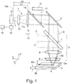
- Fig. 1 shows an exemplary structure of a device 1 for process monitoring and control of a laser cutting process on a workpiece 2 by means of a CO2 laser machining system, from the in Fig. 1 only one processing unit 3 (part of a laser processing head) with a focusing lens 4 of zinc selenide for focusing a CO2 laser beam 5 of the laser processing system, a cutting gas nozzle 6 and a deflection mirror 7 is shown.
- the deflecting mirror 7 is formed partially permeable and therefore forms an inlet-side component of the device 1 for process monitoring.
- the deflecting mirror 7 reflects the incident CO.sub.2 laser beam 5 (with a wavelength of approximately 10 .mu.m) and transmits radiation 8 relevant to process monitoring, which is reflected by the workpiece 2 and emitted by the interaction zone, in a wavelength range which in the present example is between approximately 550.degree nm and 2000 nm.
- a scraper mirror or a perforated mirror can also be used in order to supply the process radiation 8 to the device 1.
- the use of a scraper mirror typically results in masking a portion of the process radiation and limiting the beam diameter.
- the use of a perforated mirror usually leads to diffraction effects of the process radiation and to a strong influence on the (CO2) laser radiation.
- a further deflection mirror 9 is arranged behind the partially transparent mirror 7, which deflects the process radiation 8 onto a geometrically high-resolution camera 10 as an image acquisition unit.
- the camera 10 may be a high-speed camera which is arranged coaxially to the laser beam axis 11 or to extend the laser beam axis 11a and thus independent of direction.
- the possibility of taking the image by the camera 10 also results in the incident light method, i. in the VIS wavelength range, possibly also in the NIR wavelength range, if an additional illumination source is provided, which radiates in the NIR range, and alternatively the recording of the process luminescence in the wavelength ranges UV and NIR / IR.
- focusing optical system 12 is provided, which focuses the relevant for the process monitoring radiation 8 to the camera 10.
- spherical aberrations in the imaging can be prevented or at least reduced.
- a filter 13 in front of the camera 10 is advantageous if further radiation or wavelength components are to be excluded from the detection with the camera 10.
- the filter 13 may be formed, for example, as a narrow-band bandpass filter with a low half-width, in order to avoid or reduce chromatic aberrations.
- the position of the camera 10 as well as the imaging optical element 12 and / or the filter 13 along the laser beam axis 11 present in the present example can be adjusted as required by a person skilled in the art, for simplicity by a double arrow positioning system 14.
- the camera 10 is operated in the present example in incident light, that is, there is an additional illumination source 15 is provided above the workpiece 2, which via a further partially transparent mirror 16 illuminating radiation 17 coaxially coupled to the laser beam axis 11 in the beam path.
- additional Illumination source 15 may be laser diodes, for example. With a wavelength of 658 nm, or diode lasers, for example. With a wavelength of 808 nm, provided as in Fig. 1 shown coaxial, but also off-axis to the laser beam axis 11 can be arranged.
- the additional illumination source 15 may, for example, also be arranged outside (in particular next to) the processing unit 3 and directed towards the workpiece 2; Alternatively, the illumination source 15 may be disposed within the processing unit 3, but not be directed coaxially to the laser beam 5 on the workpiece 2.
- the camera 10 takes a high-resolution image 20 of a monitored area 21 (detail) of the workpiece 2.
- the image 20 is formed by the circular inner contour 6a (see FIG. Fig. 1 ) of the nozzle 6 limited.
- the image 20 shows the region 21 to be monitored during a laser fusion cutting process, in which the workpiece 2 is moved in a feed direction V BLECH relative to the nozzle 6 or to the processing unit 3 (laser processing head).
- the relative movement between the workpiece 2 and the nozzle 6 or the processing unit 3 (laser processing head) by the movement of the nozzle 6 and the processing unit 3 are executed.
- an interaction region 22, 23 forms between the laser beam 5 and the workpiece 2, which comprises a heat advance zone 22 and a cutting front 23, to which a cutting gap 24 (also referred to below as a kerf) follows in the feed direction V BLECH .
- An in Fig. 1 shown evaluation device 18 is used to evaluate the image 20 and in particular for the detection of material limitations within the monitored area 21 on the upper side 2a and the lower side 2b of the workpiece 2.
- the evaluation device 18 is connected to a also in Fig. 1 shown control device 19 in signal connection, which controls or regulates the laser cutting process, in dependence on determined by the evaluation device 18 characteristic characteristics of the laser cutting process.
- the following features of a laser cutting process can be determined by the evaluation unit 18 on the basis of the camera image 20 in order to determine characteristic parameters: Material boundaries at the workpiece top and bottom 2a, 2b, in particular edges of the workpiece, nozzle edge and nozzle center of the laser processing nozzle, geometric dimensions of Kerf (not only opposite cutting edges, but also the area of the interaction zone, eg the cutting front), position of the kerf relative to the nozzle edge / center, location of already cut regions relative to the actual cutting position, etc.
- the detection of these and other characteristics to determine characteristic Parameters of the laser processing process are described in more detail below.
- the gap width A2 of the kerf 24 is determined on the basis of the high-resolution camera image 20 by the evaluation unit 18 detecting the cut edges K1.1 and K1.2 of the kerf 24 and determining their spacing, which coincides with the kerf width A2.
- the cut edges K1.1, K1.2 generally run (nearly) parallel, so that the kerf width A2 is (almost) constant, especially in the case of a blank cut.
- the evaluation unit 18 itself or a logic downstream of it, eg the control device 19, can determine via the comparison with a previously defined and for comparison stored target cutting width, for example if a minimum cutting gap width A2 MIN falls below a cut, ie a complete absence of a kerf, or if a maximum kerf width A2 MAX is exceeded, a material burn-up (self-burning) or in the case of an oxygen-burning cut of structural steel leaching (colossi) is present or present.
- a material firing can alternatively or additionally also be determined by the (temporal) change of the kerf width A2-both with regard to an absolute change and via the rate of change.
- Several evaluation methods for the gap width can also be used in parallel.
- a material erosion leads to a widening of the cutting edges K1.1, K1.2 and the Cutting front 23, which may possibly be so large that the kerf 24 is wider than the nozzle opening 6a and the nozzle contour K3, so that the cut edges K1.1, K1.2 in the monitored area 21 are no longer recognizable.
- a cutting tear can be detected on the basis of a surface F2 which is formed between a front edge K2.1 and a rear edge K2.2 of the detected cutting front 23.
- the area F2 which corresponds to the projection of the cutting front 23 in the XY plane, is set in relation to a reference area.
- a cut-off occurs when the surface F2 reaches the size of the reference surface, ie the ratio reference surface / F2 is equal to one.
- the reference surface corresponds to the area of the projected cutting front in the case of a blank cut, ie in the case of a cut with good cutting quality.
- a cut-to-break can also be detected if the brightness of the cutting front 23 is greater than in the case of a reference blank cut, wherein the lighting can occur continuously and / or sporadically and the luminous area is approximately equal to or greater than the kerf width A2.
- FIGS. 7a-c and Fig. 8 Colings can also be described by a decrease in brightness as well as by the occurrence of flashes, ie short and intense increases in brightness in the area of the cutting front 23, typically punctually at the cutting front outside, in the region of the transition to the parallel cutting edges K1.1 , K1.2, are detected.
- the position of the tool center point P2 can also be determined via the kerf width A2, which position is also referred to below as TCP ( T ool C enter P oint).
- TCP T ool C enter P oint
- Whose position in the Y direction is defined by a center line 25 which extends parallel and centrally to the opposite cutting edges K1.1, K1.2 of the kerf 24.
- the position of the TCP P2 can also be determined in the X direction, as a center line between the edges K5.1, K5.2 another kerf 27, which in the in Fig. 2 shown example in a previous laser cutting process (with feed direction in the Y direction) was generated.
- the tool center point P2 in the XY plane (parallel to the workpiece surface) can be clearly defined. It is understood that, in principle, instead of the shown kerf 24 running perpendicular to the kerf 24, any other kerf 24 not running parallel to the kerf can be used to determine the tool center point P2 in the XY plane.
- the thus determined tool center point P2 can be used to set and monitor the nozzle position of the traversed by the laser beam 5 cutting nozzle 6, by reference to the nozzle center P1.
- the nozzle center P1 is determined from the circular nozzles (inner) contour K3 detected via the image capturing unit 10, whose center of the circle is the nozzle center P1.
- a distance A3 between the nozzle center P1 and the tool center P2 can be determined.
- the laser cutting process can be intervened with the aid of the regulating device 19 to correct the position of the laser beam 5 relative to the nozzle 6, so that the tool center point P2 coincides with the nozzle center P1.
- the inner contour K3 of the nozzle 6 it is also possible, in particular based on the geometric shape of the cutting nozzle, to conclude that it is mechanically damaged, namely by recognizing deviations from the (typically circular) desired contour of the nozzle 6.
- the injury can be generated inter alia by a collision of the nozzle 6 with the workpiece 2, with (not shown) support webs or other interference contours or by a strong Laserstrahlaußermittmaschine (relative to the nozzle center P1), in which the laser beam 5 the nozzle inner edge 6a tangent and thereby locally melted ,
- the cutting gas dynamics and thus the quality of cut can change adversely.
- a distance A4 between the cutting front upper edge K2.1 and the cutting front lower edge K2.2 is first determined, which are detected as described above with the aid of the evaluation device 18 as material boundaries.
- the lens 12 which precedes the image acquisition unit 10 is displaced along the optical axis 11 with the aid of the positioning system 14, so that a distance between an image plane 10a of the image acquisition device 10 for receiving the image 20 and the lens 12 changes.
- the workpiece 2 or its upper side 2a is within the range of the depth of field of the image capture device 10, so that at least one material boundary of the workpiece 2, eg the cut edges K1.1, K1.2 are detected can.
- the nozzle 6 is in the range of the depth of focus of the image capture device 10, so that the evaluation device 18 detects an inner contour K3 of the nozzle 6 as material boundary.
- the distance A5 between the nozzle 6 and the workpiece 2 be calculated.
- a cut end detection when reaching or passing over a sheet edge K4 is shown on the outer edge of the workpiece 2.
- the position of the detected sheet edge K4 in this case is related to the tool center point P2 to produce a (in Fig. 3 not shown) distance between the tool center point P2 and the sheet edge K4 to determine.
- the control device 19 can switch off the laser beam 5 as soon as it reaches the sheet metal edge K4, so that any injury to the separated workpiece 2 during the fall through a laser beam 5 ignited too long is avoided.
- such a switch-off can also be carried out before the sheet edge passes through the tool center point P2, as soon as the distance to the sheet edge K4 is sufficiently small in order to be able to realize a complete separation of the workpiece 2 despite the switch-off.
- Fig. 4 Analogous to Fig. 3 is in Fig. 4 a cut end detection upon reaching an already cut contour, ie an existing kerf 27, shown.
- the shutdown of the laser beam 5 can analogously to reaching or driving over the sheet edge K4 in Fig. 3 whose role in the in Fig. 4 shown image 20 is taken from the first in the direction of the cutting process facing cutting edge K5.1.
- the cutting gap width A1 and, in turn, the end point P3 of the cutting gap 24 entering the kerf 27 can be defined.
- This end point P3 is typically centered, that is arranged at the same distance (0.5 A1) to the opposite cut edges K5.1, K5.2.
- this end point P3 can also be displaced in the direction of the cutting edge K5.1 first reached through the cut, for example, if the incoming kerf 24 is larger than the already existing kerf 27 transverse to it.
- a backward displacement of the end point P3 can also be favorable as long as the laser beam 5 is switched off at least so early that a violation of the rear cutting edge 5.2 of the other kerf 27 is avoided.
- a path deviation can also be detected and corrected when the tolerance range is exceeded with the aid of the regulating device 19.
- Fig. 5 illustrated case of the detection of the beginning of cut is similar to that in the Fig. 3 and Fig. 4 described detection of the cutting end.
- the laser beam 5 is not switched off or switched on as a function of the (position) ratio of the workpiece center point P2 to the kerf 27 running transversely (or else at a different angle).
- the detection of a cut start at a plate edge K4 analogous to in connection with Fig. 3 described procedure takes place.
- a start of cut recognition is particularly suitable for the resumption of a cutting process after a cut or when resuming a cutting process after a relative movement between processing unit 3 and workpiece 2, for example. Due to clock cycles in which the process of laser cutting process interrupted and at a later Time at exactly the same place again started / must be recorded.
- Fig. 6 shows the image 20 of a monitored area 21 of the workpiece 2 in a piercing operation in which a circular hole 28 is introduced into the workpiece 2.
- the two major factors influencing the plunge process namely the chemical composition of the material and the surface finish of the workpiece 2, may vary from manufacturer to manufacturer or from lot to lot.
- piercing especially in structural steel, eg with material thicknesses from 15 mm, problems may occur during the plunge process due to these differences in material properties.
- the piercing process in the thick structural steel is disturbed in such a way that the laser beam does not drill a slender hole, but that due to the overheating and the subsequently occurring, exothermic iron-oxygen reaction, a conical crater is formed whose Contour in Fig.
- the evaluation device 18 can in this case detect the inner contour K6.1 of the hole 28 and the outer crater edge K6.2, so that an imminent crater formation can be detected and the control device 19 can initiate suitable countermeasures, for example a cooling off period.
- the introduction of countermeasures can take place, for example, when a limit value for the distance A6 between the inner boundary K6.1 and the outer boundary K6.2 (crater edge) of the piercing hole 28 is exceeded. It is understood that cratering can also be concluded when the outer contour K6.2 of the piercing hole 28 becomes so large that it disappears from the region 21 received by the camera 10 through the nozzle 6.
- FIGS. 7a 1c each show an image 20 of the process illumination in the NIR / IR region of an interaction region 31 in a fusion cutting process which was recorded with the camera 10 using a filter 13 which was permeable only to (near) infrared process radiation 8, the shown contours represent the boundaries between areas of different intensity of the process radiation 8 and the contours of the workpiece 2 are not visible.
- the process radiation 8 detected by the image 20 is an intrinsic illumination of the laser cutting process which typically (at least in part) comprises the melt pool.
- the image 20 of the process lighting can not be equated directly with a temperature distribution since the measured intensity I (see FIG. Fig.
- I ⁇ * T 4 , where ⁇ denotes the emissivity (between 0 and 1). Since the emissivity ⁇ in the present case can be close to zero, statements about the temperature are difficult to deduce from the intensity distribution. Nevertheless, for the sake of simplicity, the measured intensity distribution is sometimes also referred to as a thermal image.
- Fig. 7a shows here the image 20 of the interaction region 31, in which a quality cut (with almost smooth cut edges) is generated.
- the interaction region 31 has along the feed direction V sheet a single central tail or a single tracer track 29.
- Fig. 7b shows an image 20 of the interaction region 31 in the presence of burring, namely in the formation of a so-called Krümelgrats, in the present example, two from the cutting front 23 of backward bright fluorescent stripes 30a, 30b at the two cut edges (not shown) and a further light strip 30c can be seen, which runs in the middle between the two outer light strips 30a, 30b.
- the light strips 30a-c are hereby relatively long, which indicates the occurrence of an azimuthal melt flow with a burr formation of a crumb ridge far to the rear in the wake.
- Fig. 7c Image 20 of the interaction region 31, which is also shown, also indicates burr formation, namely on a so-called beard burr.
- burr formation namely on a so-called beard burr.
- no tail or light strip can be seen, because the complete melt volume feeds the burr.
- a thermal image 20 or an image of the process luminescence in the NIR / IR region is shown, as it occurs in a mild steel flame cutting process (using oxygen as a cutting gas).
- the upper parts of the cut edges on periodically recurring grooves which can be seen in the thermal image 20 as grooves 33.
- a local minimum 32 with a relation to the intensity in the environment reduced radiation intensity.
- the Size of the area F1 of the intensity minimum 32 (radiation sink) can be monitored and, in the event that it decreases too much, counteracted burr formation by suitably changing the process parameters.
- the frequency f of the grooves 33 in the thermal image 20 of the interaction region 31 decreases in the region of that cutting edge at which material erosion is imminent, so that suitable countermeasures can be taken to prevent the occurrence of the material erosion.
- the grooves 33 or a decrease in the frequency f of the grooves can alternatively also be detected in the VIS range.
- the thermal images 20 can be compared with the material boundaries (contours of the workpiece 2) detected (in the case of visible wavelengths) in order to improve the determination of characteristics characteristic of the laser cutting process.
- a cut break can be detected if the width of the detected in the thermal image luminous surface, which corresponds substantially to the width of the cutting front, is greater than the width A2 of the cutting gap perpendicular to the feed direction V sheet (see. Fig. 2 ).
- the wavelength filter 13 is suitably tuned in or in the beam path of the process light 8 in and out again moved out. It is understood that for the parallel detection of material limitations and thermal image, the image capture device 10 may also include other cameras or detectors.
Landscapes
- Engineering & Computer Science (AREA)
- Physics & Mathematics (AREA)
- Optics & Photonics (AREA)
- Mechanical Engineering (AREA)
- Plasma & Fusion (AREA)
- Quality & Reliability (AREA)
- Laser Beam Processing (AREA)
Priority Applications (1)
| Application Number | Priority Date | Filing Date | Title |
|---|---|---|---|
| PL17152950T PL3189926T3 (pl) | 2011-02-07 | 2012-02-01 | Urządzenie oraz sposób monitorowania, a w szczególności regulowania procesu cięcia laserowego |
Applications Claiming Priority (2)
| Application Number | Priority Date | Filing Date | Title |
|---|---|---|---|
| DE102011003717A DE102011003717A1 (de) | 2011-02-07 | 2011-02-07 | Vorrichtung und Verfahren zur Überwachung und insbesondere zur Regelung eines Laserschneidprozesses |
| EP12703051.8A EP2673108B1 (fr) | 2011-02-07 | 2012-02-01 | Machine et methode pour observer et controler un procede de coupe au laser |
Related Parent Applications (2)
| Application Number | Title | Priority Date | Filing Date |
|---|---|---|---|
| EP12703051.8A Division EP2673108B1 (fr) | 2011-02-07 | 2012-02-01 | Machine et methode pour observer et controler un procede de coupe au laser |
| EP12703051.8A Division-Into EP2673108B1 (fr) | 2011-02-07 | 2012-02-01 | Machine et methode pour observer et controler un procede de coupe au laser |
Publications (2)
| Publication Number | Publication Date |
|---|---|
| EP3189926A1 true EP3189926A1 (fr) | 2017-07-12 |
| EP3189926B1 EP3189926B1 (fr) | 2018-05-02 |
Family
ID=45569613
Family Applications (4)
| Application Number | Title | Priority Date | Filing Date |
|---|---|---|---|
| EP17152950.6A Active EP3189926B1 (fr) | 2011-02-07 | 2012-02-01 | Machine et methode pour observer, et en particulier, controler un procede de coupe au laser |
| EP19177175.7A Active EP3581323B1 (fr) | 2011-02-07 | 2012-02-01 | Dispositif et procédé de surveillance et en particulier de régulation d'un processus de découpe laser |
| EP17153946.3A Active EP3189927B1 (fr) | 2011-02-07 | 2012-02-01 | Machine et methode pour observer et controler un procede de coupe au laser |
| EP12703051.8A Active EP2673108B1 (fr) | 2011-02-07 | 2012-02-01 | Machine et methode pour observer et controler un procede de coupe au laser |
Family Applications After (3)
| Application Number | Title | Priority Date | Filing Date |
|---|---|---|---|
| EP19177175.7A Active EP3581323B1 (fr) | 2011-02-07 | 2012-02-01 | Dispositif et procédé de surveillance et en particulier de régulation d'un processus de découpe laser |
| EP17153946.3A Active EP3189927B1 (fr) | 2011-02-07 | 2012-02-01 | Machine et methode pour observer et controler un procede de coupe au laser |
| EP12703051.8A Active EP2673108B1 (fr) | 2011-02-07 | 2012-02-01 | Machine et methode pour observer et controler un procede de coupe au laser |
Country Status (7)
| Country | Link |
|---|---|
| US (3) | US20130319980A1 (fr) |
| EP (4) | EP3189926B1 (fr) |
| CN (1) | CN103347642B (fr) |
| DE (1) | DE102011003717A1 (fr) |
| ES (1) | ES2681883T3 (fr) |
| PL (2) | PL3189927T3 (fr) |
| WO (1) | WO2012107331A1 (fr) |
Cited By (2)
| Publication number | Priority date | Publication date | Assignee | Title |
|---|---|---|---|---|
| CN108846819A (zh) * | 2018-07-04 | 2018-11-20 | 深圳市创客工场科技有限公司 | 激光切割参数获取方法及装置、电子设备、存储介质 |
| WO2020104100A1 (fr) * | 2018-11-22 | 2020-05-28 | Precitec Gmbh & Co. Kg | Procédé pour couper une pièce au moyen d'un faisceau laser et système d'usinage laser utilisé pour mettre ce procédé en œuvre |
Families Citing this family (49)
| Publication number | Priority date | Publication date | Assignee | Title |
|---|---|---|---|---|
| EP2409808A1 (fr) * | 2010-07-22 | 2012-01-25 | Bystronic Laser AG | Machine de traitement au laser |
| US9289852B2 (en) * | 2011-01-27 | 2016-03-22 | Bystronic Laser Ag | Laser processing machine, laser cutting machine, and method for adjusting a focused laser beam |
| DE102011003717A1 (de) | 2011-02-07 | 2012-08-09 | Trumpf Werkzeugmaschinen Gmbh + Co. Kg | Vorrichtung und Verfahren zur Überwachung und insbesondere zur Regelung eines Laserschneidprozesses |
| US20140052420A1 (en) * | 2012-08-20 | 2014-02-20 | Ingrain Inc. | Digital Rock Analysis Systems and Methods that Estimate a Maturity Level |
| DE102013203383A1 (de) * | 2013-02-28 | 2014-08-28 | Schuler Automation Gmbh & Co. Kg | Verfahren zum Schneiden einer Blechplatine |
| US11440135B2 (en) | 2013-05-23 | 2022-09-13 | Trumpf Werkzeugmaschinen Gmbh + Co. Kg | Laser machining nozzle for a laser machining device, and laser machining device |
| WO2014187467A1 (fr) | 2013-05-23 | 2014-11-27 | Trumpf Werkzeugmaschinen Gmbh + Co. Kg | Buse de traitement au laser pour dispositif de traitement au laser et dispositif de traitement au laser |
| DE102013209526B4 (de) | 2013-05-23 | 2015-04-30 | Trumpf Werkzeugmaschinen Gmbh + Co. Kg | Verfahren, Computerprogrammprodukt und Vorrichtung zum Erkennen eines Schnittabrisses |
| DE102013210078B4 (de) * | 2013-05-29 | 2015-04-30 | Trumpf Werkzeugmaschinen Gmbh + Co. Kg | Vorrichtung, Verfahren und Computerprogrammprodukt zur Bestimmung der Fokusposition eines Hochenergiestrahls |
| DE102013218421A1 (de) | 2013-09-13 | 2015-04-02 | Trumpf Werkzeugmaschinen Gmbh + Co. Kg | Vorrichtung und Verfahren zur Überwachung, insbesondere zur Regelung, eines Schneidprozesses |
| US11440141B2 (en) | 2013-09-13 | 2022-09-13 | Trumpf Werkzeugmaschinen Gmbh + Co. Kg | Devices and methods for monitoring, in particular for regulating, a cutting process |
| EP2883647B1 (fr) | 2013-12-12 | 2019-05-29 | Bystronic Laser AG | Procédé de configuration d'un dispositif d'usinage au laser |
| DE102014202176B4 (de) * | 2014-02-06 | 2015-10-22 | Trumpf Werkzeugmaschinen Gmbh + Co. Kg | Verfahren zum Identifizieren einer Randkontur einer an einem Bearbeitungskopf gebildeten Öffnung und Bearbeitungsmaschine |
| DE102014203645B4 (de) * | 2014-02-28 | 2016-06-02 | Trumpf Werkzeugmaschinen Gmbh + Co. Kg | Verfahren und Vorrichtung zum optischen Bestimmen eines Abstandes |
| WO2015196373A1 (fr) * | 2014-06-24 | 2015-12-30 | 西门子公司 | Procédé de commande et système permettant d'utiliser une impulsion laser pour traiter un trou sur un composant creux |
| CN104607802B (zh) * | 2014-12-10 | 2017-05-17 | 深圳市华星光电技术有限公司 | 激光切割装置 |
| CN107835725B (zh) * | 2015-05-13 | 2020-05-29 | 百超激光有限公司 | 激光加工设备 |
| CN105290621B (zh) * | 2015-10-12 | 2017-07-11 | 深圳市海目星激光科技有限公司 | 一种基于视觉引导的高速高精度极耳切割方法和设备 |
| DE102015224963B3 (de) * | 2015-12-11 | 2017-04-13 | Trumpf Werkzeugmaschinen Gmbh + Co. Kg | Verfahren zur Bestimmung der Referenz-Fokuslage eines Laserstrahls |
| EP3241643A4 (fr) | 2016-03-15 | 2018-08-01 | Technology Research Association for Future Additive Manufacturing | Tête de traitement optique et dispositif de traitement optique |
| DE102016208264A1 (de) * | 2016-05-13 | 2017-11-16 | Trumpf Werkzeugmaschinen Gmbh + Co. Kg | Verfahren und Vorrichtung zur Überwachung, insbesondere zur Regelung, eines Schneidprozesses |
| DE102016211935B4 (de) | 2016-06-30 | 2019-06-06 | Sauer Gmbh | Vorrichtung und Verfahren zur Prozessüberwachung bei einem Auftragschweiß-Verfahren |
| DE102016118189B4 (de) * | 2016-09-27 | 2018-08-30 | Trumpf Werkzeugmaschinen Gmbh + Co. Kg | Verfahren und Laserbearbeitungsmaschine zum Laserschweißen eines ersten und eines zweiten Werkstückabschnitts |
| DE102016219928A1 (de) * | 2016-10-13 | 2018-04-19 | Trumpf Werkzeugmaschinen Gmbh + Co. Kg | Verfahren und Vorrichtung zur Bestimmung und zur Regelung einer Fokusposition eines Bearbeitungsstrahls |
| DE102016219927B4 (de) | 2016-10-13 | 2018-08-30 | Trumpf Werkzeugmaschinen Gmbh + Co. Kg | Vorrichtung und Verfahren zur Überwachung eines thermischen Schneidprozesses |
| DE102017107173A1 (de) * | 2017-04-04 | 2018-10-04 | Voss Fluid Gmbh | Verfahren und Vorrichtung zur Überprüfung der Vormontage eines Schneidrings auf einem Rohr |
| EP3406389A1 (fr) | 2017-05-23 | 2018-11-28 | Siemens Aktiengesellschaft | Procédé de détection et de traitement de contours définis lors du sectionnement d'un corps solide au moyen d'un faisceau de grande puissance |
| DE102017213511A1 (de) | 2017-08-03 | 2019-02-07 | Trumpf Werkzeugmaschinen Gmbh + Co. Kg | Verfahren zur Lasermaterialbearbeitung und Lasermaschine |
| WO2019110114A1 (fr) * | 2017-12-07 | 2019-06-13 | Bystronic Laser Ag | Dispositif de surveillance du traitement par faisceau d'une pièce et son utilisation, dispositif de traitement par faisceau d'une pièce et son utilisation, procédé de surveillance du traitement par faisceau d'une pièce, procédé de traitement par faisceau d'une pièce |
| EP3753667B1 (fr) * | 2018-02-16 | 2022-06-22 | Panasonic Intellectual Property Management Co., Ltd. | Dispositif de soudage au laser et procédé de soudage au laser |
| JP7053338B2 (ja) * | 2018-03-28 | 2022-04-12 | 三菱電機株式会社 | レーザ加工装置およびレーザ加工装置の調整方法 |
| JP7126221B2 (ja) * | 2018-04-13 | 2022-08-26 | パナソニックIpマネジメント株式会社 | レーザ溶接装置 |
| DE102018123363B4 (de) * | 2018-09-24 | 2021-01-07 | Bystronic Laser Ag | Verfahren zur Kollisionsvermeidung und Laserbearbeitungsmaschine |
| DE102018217526A1 (de) | 2018-10-12 | 2020-04-16 | Trumpf Werkzeugmaschinen Gmbh + Co. Kg | Verfahren zum Ermitteln einer Kenngröße eines Bearbeitungsprozesses und Bearbeitungsmaschine |
| DE102018218006A1 (de) * | 2018-10-22 | 2020-04-23 | Trumpf Werkzeugmaschinen Gmbh + Co. Kg | Verfahren und Vorrichtung zur Überwachung eines Schneidprozesses |
| JP6795567B2 (ja) * | 2018-10-30 | 2020-12-02 | ファナック株式会社 | 加工条件設定装置及び三次元レーザ加工システム |
| US20200189027A1 (en) * | 2018-12-07 | 2020-06-18 | Seoul Laser Dieboard System Co., Ltd. | Constant kerf dieboard cutting system using laser and vision |
| CN110693618B (zh) * | 2019-10-15 | 2021-11-16 | 浙江隐齿丽医学技术有限公司 | 确定壳状牙齿矫治器切割方向的方法、装置及电子设备 |
| US11305377B2 (en) | 2019-12-23 | 2022-04-19 | Precitec Gmbh & Co. Kg | Add-on module for interposing between a control device and a laser machining head of a laser machining system |
| DE102020110087A1 (de) | 2020-04-09 | 2021-10-14 | Ii-Vi Delaware, Inc. | Verfahren zur prozesskontrolle bei der lasermaterialbearbeitung |
| EP3984687A1 (fr) | 2020-10-16 | 2022-04-20 | Bystronic Laser AG | Tête de traitement du faisceau et procédé de traitement du faisceau |
| CN112991316B (zh) * | 2021-03-30 | 2022-07-01 | 中国空气动力研究与发展中心超高速空气动力研究所 | 一种模型边缘烧蚀量动态测量技术 |
| CN112950627B (zh) * | 2021-04-01 | 2023-01-20 | 上海柏楚电子科技股份有限公司 | 用于激光切割的检测及控制方法和系统 |
| EP4145233A1 (fr) | 2021-09-03 | 2023-03-08 | Bystronic Laser AG | Détermination du contour pour une machine de découpage au laser |
| CN113787574A (zh) * | 2021-11-16 | 2021-12-14 | 四川兴事发木业有限公司 | 木门生产用智能分割装置及系统 |
| DE102022101274A1 (de) | 2022-01-20 | 2023-07-20 | TRUMPF Werkzeugmaschinen SE + Co. KG | Verfahren und Messanordnung zur Bestimmung der Eigenschaften einer Laserschmelzschneidvorrichtung |
| DE102022101323A1 (de) | 2022-01-20 | 2023-07-20 | TRUMPF Werkzeugmaschinen SE + Co. KG | Laserschneideverfahren mit Einstellen der Fokuslage |
| DE102022121341A1 (de) | 2022-08-24 | 2024-02-29 | TRUMPF Werkzeugmaschinen SE + Co. KG | Laserschneiden eines Werkstücks unter Schutz der Bearbeitungsvorrichtung |
| CN115673530B (zh) * | 2022-11-18 | 2023-08-04 | 群升集团有限公司 | 具有自动报警器防火门的智能生产设备 |
Citations (12)
| Publication number | Priority date | Publication date | Assignee | Title |
|---|---|---|---|---|
| WO1991004828A1 (fr) | 1989-09-27 | 1991-04-18 | Australian Electro Optics Pty. Ltd. | Decoupeuse a rayon laser multi-axe et haute puissance avec moniteur de traitement d'image |
| JPH07116885A (ja) | 1993-10-22 | 1995-05-09 | Mitsubishi Heavy Ind Ltd | 厚板の高品質レーザ切断方法 |
| JPH11320149A (ja) | 1998-05-07 | 1999-11-24 | Koike Sanso Kogyo Co Ltd | レーザー切断機に於ける切断状態の検出装置 |
| DE4336136C2 (de) | 1992-12-28 | 2001-03-15 | Mitsubishi Electric Corp | Laserbearbeitungsvorrichtung und -verfahren |
| DE10129751A1 (de) | 2000-06-26 | 2002-01-03 | Whitney Co W | Verfahren und Einrichtung zur Steuerung einer mit einem Laser ausgerüsteten Werkzeugmaschine |
| DE10256262A1 (de) * | 2002-12-03 | 2004-06-24 | Robert Bosch Gmbh | Verfahren und Vorrichtung zur Prozesskontrolle bei der Laserbearbeitung von Bauteilen |
| DE102005024085A1 (de) | 2005-05-25 | 2006-11-30 | Precitec Kg | Vorrichtung zur Überwachung eines Laserbearbeitungsvorgangs und Laserbearbeitungskopf |
| EP1728581A1 (fr) | 2005-05-31 | 2006-12-06 | Trumpf Werkzeugmaschinen GmbH + Co. KG | Machine d'usinage laser avec des moyens d'ajustement de la buse pour aligner le faisceau laser avec le trou de passage du faisceau laser dans la buse |
| DE102008053397A1 (de) * | 2008-05-20 | 2009-12-03 | Fraunhofer-Gesellschaft zur Förderung der angewandten Forschung e.V. | Verfahren zum Schmelzschneiden von Werkstücken mit Laserstrahlung |
| DE102008030374A1 (de) * | 2008-06-26 | 2009-12-31 | Trumpf Laser- Und Systemtechnik Gmbh | Verfahren zum Laserschneiden und CO2-Laserschneidmaschine |
| DE102008051459A1 (de) | 2008-10-09 | 2010-05-12 | Hochschule Mittweida (Fh) | Einrichtung zur unmittelbaren Messung bei schichtweiser Bearbeitung von Körpern mittels Laserstrahlung wenigstens eines Lasers |
| WO2010057661A1 (fr) * | 2008-11-21 | 2010-05-27 | Precitec Kg | Procédé et dispositif de surveillance d'un processus d'usinage au laser exécuté sur une pièce, ainsi que tête d'usinage au laser équipée d'un tel dispositif |
Family Cites Families (18)
| Publication number | Priority date | Publication date | Assignee | Title |
|---|---|---|---|---|
| DE436136C (de) | 1923-10-16 | 1926-10-30 | Telefunken Gmbh | Einrichtung zur Hochfrequenztelephonie laengs Hochspannungsleitungen |
| JPH07116885B2 (ja) | 1986-03-26 | 1995-12-18 | 松下電工株式会社 | 間仕切り装置 |
| US5011626A (en) * | 1988-06-13 | 1991-04-30 | Rolls-Royce Inc. | Barrier materials for laser drilling |
| US5140127A (en) * | 1989-09-20 | 1992-08-18 | Rolls-Royce Plc | Laser barrier material |
| JP2680973B2 (ja) * | 1992-06-19 | 1997-11-19 | ファナック株式会社 | レーザ加工装置 |
| US5589090A (en) * | 1994-01-31 | 1996-12-31 | Song; Byung-Jun | Laser cutting apparatus with means for measuring cutting groove width |
| JP3162254B2 (ja) * | 1995-01-17 | 2001-04-25 | 三菱電機株式会社 | レーザ加工装置 |
| DE19716293C2 (de) * | 1997-04-18 | 2000-07-13 | Daimler Chrysler Ag | Vorrichtung zur Regelung der Fokuslage beim Laserstrahlschweißen |
| US6054673A (en) * | 1997-09-17 | 2000-04-25 | General Electric Company | Method and apparatus for laser drilling |
| JP2001053443A (ja) * | 1999-08-06 | 2001-02-23 | Hitachi Ltd | 電子回路基板の製造方法,電子回路基板の製造装置及び電子回路基板 |
| DE10036146C1 (de) * | 2000-07-25 | 2002-01-17 | Fraunhofer Ges Forschung | Verfahren zum Schneiden von Werkstücken mit einem Schneidstrahl |
| DE102004052323B4 (de) * | 2004-10-27 | 2008-01-24 | Fraunhofer-Gesellschaft zur Förderung der angewandten Forschung e.V. | Verfahren zum Trennen von Werkstoffen mit einem Laserstrahl |
| US8319145B2 (en) * | 2006-07-10 | 2012-11-27 | Lazare Kaplan International, Inc. | System and method for gemstone micro-inscription |
| EP1886757B1 (fr) * | 2006-08-07 | 2009-07-01 | LVD Company NV | Arrangement et procédé pour le contrôle en ligne de la qualité d'un procédé laser sur une pièce utilisant une caméra détectrice de chaleur et un miroir incliné |
| DE102007018416A1 (de) * | 2006-10-24 | 2008-04-30 | Messer Cutting & Welding Gmbh | Verfahren und Vorrichtung zum maschinellen Schneiden eines plattenförmigen Werkstücks |
| DE102008030783B3 (de) | 2008-06-28 | 2009-08-13 | Trumpf Werkzeugmaschinen Gmbh + Co. Kg | Verfahren zum Laserstrahlschrägschneiden und Laserbearbeitungsmaschine |
| CN101898280A (zh) * | 2010-04-30 | 2010-12-01 | 合肥中辰轻工机械有限公司 | 一种通过激光切割工件的应用方法 |
| DE102011003717A1 (de) | 2011-02-07 | 2012-08-09 | Trumpf Werkzeugmaschinen Gmbh + Co. Kg | Vorrichtung und Verfahren zur Überwachung und insbesondere zur Regelung eines Laserschneidprozesses |
-
2011
- 2011-02-07 DE DE102011003717A patent/DE102011003717A1/de not_active Withdrawn
-
2012
- 2012-02-01 EP EP17152950.6A patent/EP3189926B1/fr active Active
- 2012-02-01 EP EP19177175.7A patent/EP3581323B1/fr active Active
- 2012-02-01 PL PL17153946T patent/PL3189927T3/pl unknown
- 2012-02-01 EP EP17153946.3A patent/EP3189927B1/fr active Active
- 2012-02-01 PL PL17152950T patent/PL3189926T3/pl unknown
- 2012-02-01 EP EP12703051.8A patent/EP2673108B1/fr active Active
- 2012-02-01 WO PCT/EP2012/051634 patent/WO2012107331A1/fr active Application Filing
- 2012-02-01 ES ES17152950.6T patent/ES2681883T3/es active Active
- 2012-02-01 CN CN201280007963.3A patent/CN103347642B/zh active Active
-
2013
- 2013-08-07 US US13/961,596 patent/US20130319980A1/en not_active Abandoned
-
2017
- 2017-01-30 US US15/419,190 patent/US10058953B2/en active Active
-
2018
- 2018-07-26 US US16/046,010 patent/US10888954B2/en active Active
Patent Citations (12)
| Publication number | Priority date | Publication date | Assignee | Title |
|---|---|---|---|---|
| WO1991004828A1 (fr) | 1989-09-27 | 1991-04-18 | Australian Electro Optics Pty. Ltd. | Decoupeuse a rayon laser multi-axe et haute puissance avec moniteur de traitement d'image |
| DE4336136C2 (de) | 1992-12-28 | 2001-03-15 | Mitsubishi Electric Corp | Laserbearbeitungsvorrichtung und -verfahren |
| JPH07116885A (ja) | 1993-10-22 | 1995-05-09 | Mitsubishi Heavy Ind Ltd | 厚板の高品質レーザ切断方法 |
| JPH11320149A (ja) | 1998-05-07 | 1999-11-24 | Koike Sanso Kogyo Co Ltd | レーザー切断機に於ける切断状態の検出装置 |
| DE10129751A1 (de) | 2000-06-26 | 2002-01-03 | Whitney Co W | Verfahren und Einrichtung zur Steuerung einer mit einem Laser ausgerüsteten Werkzeugmaschine |
| DE10256262A1 (de) * | 2002-12-03 | 2004-06-24 | Robert Bosch Gmbh | Verfahren und Vorrichtung zur Prozesskontrolle bei der Laserbearbeitung von Bauteilen |
| DE102005024085A1 (de) | 2005-05-25 | 2006-11-30 | Precitec Kg | Vorrichtung zur Überwachung eines Laserbearbeitungsvorgangs und Laserbearbeitungskopf |
| EP1728581A1 (fr) | 2005-05-31 | 2006-12-06 | Trumpf Werkzeugmaschinen GmbH + Co. KG | Machine d'usinage laser avec des moyens d'ajustement de la buse pour aligner le faisceau laser avec le trou de passage du faisceau laser dans la buse |
| DE102008053397A1 (de) * | 2008-05-20 | 2009-12-03 | Fraunhofer-Gesellschaft zur Förderung der angewandten Forschung e.V. | Verfahren zum Schmelzschneiden von Werkstücken mit Laserstrahlung |
| DE102008030374A1 (de) * | 2008-06-26 | 2009-12-31 | Trumpf Laser- Und Systemtechnik Gmbh | Verfahren zum Laserschneiden und CO2-Laserschneidmaschine |
| DE102008051459A1 (de) | 2008-10-09 | 2010-05-12 | Hochschule Mittweida (Fh) | Einrichtung zur unmittelbaren Messung bei schichtweiser Bearbeitung von Körpern mittels Laserstrahlung wenigstens eines Lasers |
| WO2010057661A1 (fr) * | 2008-11-21 | 2010-05-27 | Precitec Kg | Procédé et dispositif de surveillance d'un processus d'usinage au laser exécuté sur une pièce, ainsi que tête d'usinage au laser équipée d'un tel dispositif |
Cited By (4)
| Publication number | Priority date | Publication date | Assignee | Title |
|---|---|---|---|---|
| CN108846819A (zh) * | 2018-07-04 | 2018-11-20 | 深圳市创客工场科技有限公司 | 激光切割参数获取方法及装置、电子设备、存储介质 |
| CN108846819B (zh) * | 2018-07-04 | 2022-05-27 | 深圳市创客工场科技有限公司 | 激光切割参数获取方法及装置、电子设备、存储介质 |
| WO2020104100A1 (fr) * | 2018-11-22 | 2020-05-28 | Precitec Gmbh & Co. Kg | Procédé pour couper une pièce au moyen d'un faisceau laser et système d'usinage laser utilisé pour mettre ce procédé en œuvre |
| DE102018129407B4 (de) | 2018-11-22 | 2023-03-30 | Precitec Gmbh & Co. Kg | Verfahren zum Schneiden eines Werkstücks mittels eines Laserstrahls und Laserbearbeitungssystem zum Durchführen des Verfahrens |
Also Published As
| Publication number | Publication date |
|---|---|
| PL3189926T3 (pl) | 2018-11-30 |
| ES2681883T3 (es) | 2018-09-17 |
| EP3189927B1 (fr) | 2020-04-15 |
| US20180326534A1 (en) | 2018-11-15 |
| CN103347642B (zh) | 2016-08-10 |
| EP3581323B1 (fr) | 2020-09-23 |
| EP3581323A1 (fr) | 2019-12-18 |
| EP3189926B1 (fr) | 2018-05-02 |
| PL3189927T3 (pl) | 2020-10-19 |
| US10058953B2 (en) | 2018-08-28 |
| US20170136573A1 (en) | 2017-05-18 |
| US10888954B2 (en) | 2021-01-12 |
| DE102011003717A1 (de) | 2012-08-09 |
| EP3189927A1 (fr) | 2017-07-12 |
| EP2673108A1 (fr) | 2013-12-18 |
| WO2012107331A1 (fr) | 2012-08-16 |
| CN103347642A (zh) | 2013-10-09 |
| US20130319980A1 (en) | 2013-12-05 |
| EP2673108B1 (fr) | 2017-03-29 |
Similar Documents
| Publication | Publication Date | Title |
|---|---|---|
| EP2673108B1 (fr) | Machine et methode pour observer et controler un procede de coupe au laser | |
| EP3043951B1 (fr) | Dispositif et procédé de surveillance, et en particulier de réglage, d'un processus de coupe | |
| EP3294488B1 (fr) | Dispositif de decoupe laser avec un systeme d'observation | |
| EP2805791B1 (fr) | Procédé et dispositif de détection d'une ébauche de coupe | |
| DE4336136C2 (de) | Laserbearbeitungsvorrichtung und -verfahren | |
| EP3455028B1 (fr) | Procédé et dispositif de surveillance, en particulier de réglage, d'un processus de coupe | |
| EP2908981B1 (fr) | Méthode et machine d'usinage pour rainurer, percer ou découper des pièces métalliques, avec détermination de l'intensité de la radiation d'usinage | |
| DE102016219927B4 (de) | Vorrichtung und Verfahren zur Überwachung eines thermischen Schneidprozesses | |
| EP3525975B1 (fr) | Procédé et dispositif pour la détermination et la régulation d'une position focale d'un faisceau d'usinage | |
| DE102006015383B4 (de) | Vorrichtung und Verfahren zur Laserverschweißung eines ersten Werkstücks mit einem zweiten Werkstück | |
| WO2015106775A1 (fr) | Procédé de surveillance et de réglage de la position focale d'un faisceau laser d'usinage lors de la découpe au laser | |
| WO2020083884A1 (fr) | Procédé et dispositif de surveillance d'un processus de découpe | |
| DE10248458B4 (de) | Verfahren und Vorrichtung zum Einstellen der Fokuslage eines auf ein Werkstück gerichteten Laserstrahls | |
| DE10256262B4 (de) | Verfahren zur Prozesskontrolle bei der Laserbearbeitung von Bauteilen, Vorrichtung zur Laserbearbeitung sowie Computerprogramm und Computerprogrammprodukt zur Durchführung des Verfahrens | |
| DE102004057799B4 (de) | Verfahren und Vorrichtung zum Regeln eines Pulverbeschichtungsprozesses | |
| DE102022106605A1 (de) | Laserbearbeitungsverfahren und Laserbearbeitungsmaschine |
Legal Events
| Date | Code | Title | Description |
|---|---|---|---|
| PUAI | Public reference made under article 153(3) epc to a published international application that has entered the european phase |
Free format text: ORIGINAL CODE: 0009012 |
|
| STAA | Information on the status of an ep patent application or granted ep patent |
Free format text: STATUS: THE APPLICATION HAS BEEN PUBLISHED |
|
| STAA | Information on the status of an ep patent application or granted ep patent |
Free format text: STATUS: REQUEST FOR EXAMINATION WAS MADE |
|
| AC | Divisional application: reference to earlier application |
Ref document number: 2673108 Country of ref document: EP Kind code of ref document: P |
|
| AK | Designated contracting states |
Kind code of ref document: A1 Designated state(s): AL AT BE BG CH CY CZ DE DK EE ES FI FR GB GR HR HU IE IS IT LI LT LU LV MC MK MT NL NO PL PT RO RS SE SI SK SM TR |
|
| 17P | Request for examination filed |
Effective date: 20170622 |
|
| RBV | Designated contracting states (corrected) |
Designated state(s): AL AT BE BG CH CY CZ DE DK EE ES FI FR GB GR HR HU IE IS IT LI LT LU LV MC MK MT NL NO PL PT RO RS SE SI SK SM TR |
|
| GRAP | Despatch of communication of intention to grant a patent |
Free format text: ORIGINAL CODE: EPIDOSNIGR1 |
|
| STAA | Information on the status of an ep patent application or granted ep patent |
Free format text: STATUS: GRANT OF PATENT IS INTENDED |
|
| INTG | Intention to grant announced |
Effective date: 20171122 |
|
| GRAS | Grant fee paid |
Free format text: ORIGINAL CODE: EPIDOSNIGR3 |
|
| GRAA | (expected) grant |
Free format text: ORIGINAL CODE: 0009210 |
|
| STAA | Information on the status of an ep patent application or granted ep patent |
Free format text: STATUS: THE PATENT HAS BEEN GRANTED |
|
| AC | Divisional application: reference to earlier application |
Ref document number: 2673108 Country of ref document: EP Kind code of ref document: P |
|
| AK | Designated contracting states |
Kind code of ref document: B1 Designated state(s): AL AT BE BG CH CY CZ DE DK EE ES FI FR GB GR HR HU IE IS IT LI LT LU LV MC MK MT NL NO PL PT RO RS SE SI SK SM TR |
|
| REG | Reference to a national code |
Ref country code: GB Ref legal event code: FG4D Free format text: NOT ENGLISH |
|
| REG | Reference to a national code |
Ref country code: CH Ref legal event code: EP Ref country code: AT Ref legal event code: REF Ref document number: 994681 Country of ref document: AT Kind code of ref document: T Effective date: 20180515 |
|
| REG | Reference to a national code |
Ref country code: DE Ref legal event code: R096 Ref document number: 502012012647 Country of ref document: DE Ref country code: IE Ref legal event code: FG4D Free format text: LANGUAGE OF EP DOCUMENT: GERMAN |
|
| REG | Reference to a national code |
Ref country code: NL Ref legal event code: MP Effective date: 20180502 |
|
| REG | Reference to a national code |
Ref country code: ES Ref legal event code: FG2A Ref document number: 2681883 Country of ref document: ES Kind code of ref document: T3 Effective date: 20180917 |
|
| REG | Reference to a national code |
Ref country code: LT Ref legal event code: MG4D |
|
| PG25 | Lapsed in a contracting state [announced via postgrant information from national office to epo] |
Ref country code: LT Free format text: LAPSE BECAUSE OF FAILURE TO SUBMIT A TRANSLATION OF THE DESCRIPTION OR TO PAY THE FEE WITHIN THE PRESCRIBED TIME-LIMIT Effective date: 20180502 Ref country code: SE Free format text: LAPSE BECAUSE OF FAILURE TO SUBMIT A TRANSLATION OF THE DESCRIPTION OR TO PAY THE FEE WITHIN THE PRESCRIBED TIME-LIMIT Effective date: 20180502 Ref country code: NO Free format text: LAPSE BECAUSE OF FAILURE TO SUBMIT A TRANSLATION OF THE DESCRIPTION OR TO PAY THE FEE WITHIN THE PRESCRIBED TIME-LIMIT Effective date: 20180802 Ref country code: FI Free format text: LAPSE BECAUSE OF FAILURE TO SUBMIT A TRANSLATION OF THE DESCRIPTION OR TO PAY THE FEE WITHIN THE PRESCRIBED TIME-LIMIT Effective date: 20180502 Ref country code: BG Free format text: LAPSE BECAUSE OF FAILURE TO SUBMIT A TRANSLATION OF THE DESCRIPTION OR TO PAY THE FEE WITHIN THE PRESCRIBED TIME-LIMIT Effective date: 20180802 |
|
| PG25 | Lapsed in a contracting state [announced via postgrant information from national office to epo] |
Ref country code: RS Free format text: LAPSE BECAUSE OF FAILURE TO SUBMIT A TRANSLATION OF THE DESCRIPTION OR TO PAY THE FEE WITHIN THE PRESCRIBED TIME-LIMIT Effective date: 20180502 Ref country code: NL Free format text: LAPSE BECAUSE OF FAILURE TO SUBMIT A TRANSLATION OF THE DESCRIPTION OR TO PAY THE FEE WITHIN THE PRESCRIBED TIME-LIMIT Effective date: 20180502 Ref country code: LV Free format text: LAPSE BECAUSE OF FAILURE TO SUBMIT A TRANSLATION OF THE DESCRIPTION OR TO PAY THE FEE WITHIN THE PRESCRIBED TIME-LIMIT Effective date: 20180502 Ref country code: GR Free format text: LAPSE BECAUSE OF FAILURE TO SUBMIT A TRANSLATION OF THE DESCRIPTION OR TO PAY THE FEE WITHIN THE PRESCRIBED TIME-LIMIT Effective date: 20180803 Ref country code: HR Free format text: LAPSE BECAUSE OF FAILURE TO SUBMIT A TRANSLATION OF THE DESCRIPTION OR TO PAY THE FEE WITHIN THE PRESCRIBED TIME-LIMIT Effective date: 20180502 |
|
| PG25 | Lapsed in a contracting state [announced via postgrant information from national office to epo] |
Ref country code: SK Free format text: LAPSE BECAUSE OF FAILURE TO SUBMIT A TRANSLATION OF THE DESCRIPTION OR TO PAY THE FEE WITHIN THE PRESCRIBED TIME-LIMIT Effective date: 20180502 Ref country code: EE Free format text: LAPSE BECAUSE OF FAILURE TO SUBMIT A TRANSLATION OF THE DESCRIPTION OR TO PAY THE FEE WITHIN THE PRESCRIBED TIME-LIMIT Effective date: 20180502 Ref country code: DK Free format text: LAPSE BECAUSE OF FAILURE TO SUBMIT A TRANSLATION OF THE DESCRIPTION OR TO PAY THE FEE WITHIN THE PRESCRIBED TIME-LIMIT Effective date: 20180502 Ref country code: RO Free format text: LAPSE BECAUSE OF FAILURE TO SUBMIT A TRANSLATION OF THE DESCRIPTION OR TO PAY THE FEE WITHIN THE PRESCRIBED TIME-LIMIT Effective date: 20180502 |
|
| REG | Reference to a national code |
Ref country code: DE Ref legal event code: R097 Ref document number: 502012012647 Country of ref document: DE |
|
| PG25 | Lapsed in a contracting state [announced via postgrant information from national office to epo] |
Ref country code: SM Free format text: LAPSE BECAUSE OF FAILURE TO SUBMIT A TRANSLATION OF THE DESCRIPTION OR TO PAY THE FEE WITHIN THE PRESCRIBED TIME-LIMIT Effective date: 20180502 |
|
| PLBE | No opposition filed within time limit |
Free format text: ORIGINAL CODE: 0009261 |
|
| STAA | Information on the status of an ep patent application or granted ep patent |
Free format text: STATUS: NO OPPOSITION FILED WITHIN TIME LIMIT |
|
| 26N | No opposition filed |
Effective date: 20190205 |
|
| PG25 | Lapsed in a contracting state [announced via postgrant information from national office to epo] |
Ref country code: LU Free format text: LAPSE BECAUSE OF NON-PAYMENT OF DUE FEES Effective date: 20190201 Ref country code: MC Free format text: LAPSE BECAUSE OF FAILURE TO SUBMIT A TRANSLATION OF THE DESCRIPTION OR TO PAY THE FEE WITHIN THE PRESCRIBED TIME-LIMIT Effective date: 20180502 |
|
| REG | Reference to a national code |
Ref country code: BE Ref legal event code: MM Effective date: 20190228 |
|
| REG | Reference to a national code |
Ref country code: IE Ref legal event code: MM4A |
|
| PG25 | Lapsed in a contracting state [announced via postgrant information from national office to epo] |
Ref country code: AL Free format text: LAPSE BECAUSE OF FAILURE TO SUBMIT A TRANSLATION OF THE DESCRIPTION OR TO PAY THE FEE WITHIN THE PRESCRIBED TIME-LIMIT Effective date: 20180502 |
|
| PG25 | Lapsed in a contracting state [announced via postgrant information from national office to epo] |
Ref country code: IE Free format text: LAPSE BECAUSE OF NON-PAYMENT OF DUE FEES Effective date: 20190201 |
|
| PG25 | Lapsed in a contracting state [announced via postgrant information from national office to epo] |
Ref country code: BE Free format text: LAPSE BECAUSE OF NON-PAYMENT OF DUE FEES Effective date: 20190228 |
|
| PG25 | Lapsed in a contracting state [announced via postgrant information from national office to epo] |
Ref country code: TR Free format text: LAPSE BECAUSE OF FAILURE TO SUBMIT A TRANSLATION OF THE DESCRIPTION OR TO PAY THE FEE WITHIN THE PRESCRIBED TIME-LIMIT Effective date: 20180502 |
|
| REG | Reference to a national code |
Ref country code: AT Ref legal event code: MM01 Ref document number: 994681 Country of ref document: AT Kind code of ref document: T Effective date: 20190201 |
|
| PG25 | Lapsed in a contracting state [announced via postgrant information from national office to epo] |
Ref country code: AT Free format text: LAPSE BECAUSE OF NON-PAYMENT OF DUE FEES Effective date: 20190201 |
|
| PG25 | Lapsed in a contracting state [announced via postgrant information from national office to epo] |
Ref country code: MT Free format text: LAPSE BECAUSE OF FAILURE TO SUBMIT A TRANSLATION OF THE DESCRIPTION OR TO PAY THE FEE WITHIN THE PRESCRIBED TIME-LIMIT Effective date: 20180502 Ref country code: PT Free format text: LAPSE BECAUSE OF FAILURE TO SUBMIT A TRANSLATION OF THE DESCRIPTION OR TO PAY THE FEE WITHIN THE PRESCRIBED TIME-LIMIT Effective date: 20180903 |
|
| PG25 | Lapsed in a contracting state [announced via postgrant information from national office to epo] |
Ref country code: CY Free format text: LAPSE BECAUSE OF FAILURE TO SUBMIT A TRANSLATION OF THE DESCRIPTION OR TO PAY THE FEE WITHIN THE PRESCRIBED TIME-LIMIT Effective date: 20180502 |
|
| PG25 | Lapsed in a contracting state [announced via postgrant information from national office to epo] |
Ref country code: IS Free format text: LAPSE BECAUSE OF FAILURE TO SUBMIT A TRANSLATION OF THE DESCRIPTION OR TO PAY THE FEE WITHIN THE PRESCRIBED TIME-LIMIT Effective date: 20180902 |
|
| PG25 | Lapsed in a contracting state [announced via postgrant information from national office to epo] |
Ref country code: HU Free format text: LAPSE BECAUSE OF FAILURE TO SUBMIT A TRANSLATION OF THE DESCRIPTION OR TO PAY THE FEE WITHIN THE PRESCRIBED TIME-LIMIT; INVALID AB INITIO Effective date: 20120201 |
|
| PG25 | Lapsed in a contracting state [announced via postgrant information from national office to epo] |
Ref country code: SI Free format text: LAPSE BECAUSE OF FAILURE TO SUBMIT A TRANSLATION OF THE DESCRIPTION OR TO PAY THE FEE WITHIN THE PRESCRIBED TIME-LIMIT Effective date: 20180502 |
|
| PGFP | Annual fee paid to national office [announced via postgrant information from national office to epo] |
Ref country code: GB Payment date: 20220223 Year of fee payment: 11 Ref country code: CH Payment date: 20220216 Year of fee payment: 11 |
|
| PGFP | Annual fee paid to national office [announced via postgrant information from national office to epo] |
Ref country code: FR Payment date: 20220216 Year of fee payment: 11 Ref country code: CZ Payment date: 20220131 Year of fee payment: 11 |
|
| PG25 | Lapsed in a contracting state [announced via postgrant information from national office to epo] |
Ref country code: MK Free format text: LAPSE BECAUSE OF FAILURE TO SUBMIT A TRANSLATION OF THE DESCRIPTION OR TO PAY THE FEE WITHIN THE PRESCRIBED TIME-LIMIT Effective date: 20180502 |
|
| PGFP | Annual fee paid to national office [announced via postgrant information from national office to epo] |
Ref country code: ES Payment date: 20220426 Year of fee payment: 11 |
|
| PGFP | Annual fee paid to national office [announced via postgrant information from national office to epo] |
Ref country code: PL Payment date: 20230123 Year of fee payment: 12 Ref country code: IT Payment date: 20230223 Year of fee payment: 12 |
|
| REG | Reference to a national code |
Ref country code: CH Ref legal event code: PL |
|
| GBPC | Gb: european patent ceased through non-payment of renewal fee |
Effective date: 20230201 |
|
| PG25 | Lapsed in a contracting state [announced via postgrant information from national office to epo] |
Ref country code: LI Free format text: LAPSE BECAUSE OF NON-PAYMENT OF DUE FEES Effective date: 20230228 Ref country code: CZ Free format text: LAPSE BECAUSE OF NON-PAYMENT OF DUE FEES Effective date: 20230201 Ref country code: CH Free format text: LAPSE BECAUSE OF NON-PAYMENT OF DUE FEES Effective date: 20230228 |
|
| PG25 | Lapsed in a contracting state [announced via postgrant information from national office to epo] |
Ref country code: GB Free format text: LAPSE BECAUSE OF NON-PAYMENT OF DUE FEES Effective date: 20230201 |
|
| PG25 | Lapsed in a contracting state [announced via postgrant information from national office to epo] |
Ref country code: GB Free format text: LAPSE BECAUSE OF NON-PAYMENT OF DUE FEES Effective date: 20230201 Ref country code: FR Free format text: LAPSE BECAUSE OF NON-PAYMENT OF DUE FEES Effective date: 20230228 |
|
| REG | Reference to a national code |
Ref country code: ES Ref legal event code: FD2A Effective date: 20240404 |
|
| PG25 | Lapsed in a contracting state [announced via postgrant information from national office to epo] |
Ref country code: ES Free format text: LAPSE BECAUSE OF NON-PAYMENT OF DUE FEES Effective date: 20230202 |
|
| PG25 | Lapsed in a contracting state [announced via postgrant information from national office to epo] |
Ref country code: ES Free format text: LAPSE BECAUSE OF NON-PAYMENT OF DUE FEES Effective date: 20230202 |
|
| PGFP | Annual fee paid to national office [announced via postgrant information from national office to epo] |
Ref country code: DE Payment date: 20240219 Year of fee payment: 13 |