EP3180195B2 - Druckmodul mit frontseitig auswechselbarem druckkopf - Google Patents
Druckmodul mit frontseitig auswechselbarem druckkopf Download PDFInfo
- Publication number
- EP3180195B2 EP3180195B2 EP15744881.2A EP15744881A EP3180195B2 EP 3180195 B2 EP3180195 B2 EP 3180195B2 EP 15744881 A EP15744881 A EP 15744881A EP 3180195 B2 EP3180195 B2 EP 3180195B2
- Authority
- EP
- European Patent Office
- Prior art keywords
- printing
- printing module
- printing head
- print head
- module
- Prior art date
- Legal status (The legal status is an assumption and is not a legal conclusion. Google has not performed a legal analysis and makes no representation as to the accuracy of the status listed.)
- Active
Links
- 238000007639 printing Methods 0.000 title claims description 89
- 238000010168 coupling process Methods 0.000 claims description 34
- 238000005859 coupling reaction Methods 0.000 claims description 34
- 230000008878 coupling Effects 0.000 claims description 28
- 230000008439 repair process Effects 0.000 claims description 18
- 238000003780 insertion Methods 0.000 claims description 5
- 230000037431 insertion Effects 0.000 claims description 5
- 230000005484 gravity Effects 0.000 claims description 4
- 238000000151 deposition Methods 0.000 claims 5
- 238000009434 installation Methods 0.000 claims 5
- 238000007599 discharging Methods 0.000 claims 1
- 238000000034 method Methods 0.000 description 12
- 230000008859 change Effects 0.000 description 8
- 239000012530 fluid Substances 0.000 description 6
- 230000008569 process Effects 0.000 description 4
- 238000010438 heat treatment Methods 0.000 description 2
- 238000007641 inkjet printing Methods 0.000 description 2
- 230000008901 benefit Effects 0.000 description 1
- 238000010276 construction Methods 0.000 description 1
- 238000007667 floating Methods 0.000 description 1
- 238000012423 maintenance Methods 0.000 description 1
- 238000004519 manufacturing process Methods 0.000 description 1
- 239000000463 material Substances 0.000 description 1
- 230000013011 mating Effects 0.000 description 1
- 238000007789 sealing Methods 0.000 description 1
Images

Classifications
-
- B—PERFORMING OPERATIONS; TRANSPORTING
- B41—PRINTING; LINING MACHINES; TYPEWRITERS; STAMPS
- B41J—TYPEWRITERS; SELECTIVE PRINTING MECHANISMS, i.e. MECHANISMS PRINTING OTHERWISE THAN FROM A FORME; CORRECTION OF TYPOGRAPHICAL ERRORS
- B41J2/00—Typewriters or selective printing mechanisms characterised by the printing or marking process for which they are designed
- B41J2/005—Typewriters or selective printing mechanisms characterised by the printing or marking process for which they are designed characterised by bringing liquid or particles selectively into contact with a printing material
- B41J2/01—Ink jet
- B41J2/135—Nozzles
- B41J2/145—Arrangement thereof
-
- B—PERFORMING OPERATIONS; TRANSPORTING
- B41—PRINTING; LINING MACHINES; TYPEWRITERS; STAMPS
- B41J—TYPEWRITERS; SELECTIVE PRINTING MECHANISMS, i.e. MECHANISMS PRINTING OTHERWISE THAN FROM A FORME; CORRECTION OF TYPOGRAPHICAL ERRORS
- B41J2/00—Typewriters or selective printing mechanisms characterised by the printing or marking process for which they are designed
- B41J2/005—Typewriters or selective printing mechanisms characterised by the printing or marking process for which they are designed characterised by bringing liquid or particles selectively into contact with a printing material
- B41J2/01—Ink jet
- B41J2/17—Ink jet characterised by ink handling
- B41J2/175—Ink supply systems ; Circuit parts therefor
- B41J2/17503—Ink cartridges
- B41J2/1752—Mounting within the printer
-
- B—PERFORMING OPERATIONS; TRANSPORTING
- B41—PRINTING; LINING MACHINES; TYPEWRITERS; STAMPS
- B41J—TYPEWRITERS; SELECTIVE PRINTING MECHANISMS, i.e. MECHANISMS PRINTING OTHERWISE THAN FROM A FORME; CORRECTION OF TYPOGRAPHICAL ERRORS
- B41J25/00—Actions or mechanisms not otherwise provided for
- B41J25/34—Bodily-changeable print heads or carriages
-
- B—PERFORMING OPERATIONS; TRANSPORTING
- B41—PRINTING; LINING MACHINES; TYPEWRITERS; STAMPS
- B41J—TYPEWRITERS; SELECTIVE PRINTING MECHANISMS, i.e. MECHANISMS PRINTING OTHERWISE THAN FROM A FORME; CORRECTION OF TYPOGRAPHICAL ERRORS
- B41J3/00—Typewriters or selective printing or marking mechanisms characterised by the purpose for which they are constructed
- B41J3/54—Typewriters or selective printing or marking mechanisms characterised by the purpose for which they are constructed with two or more sets of type or printing elements
- B41J3/543—Typewriters or selective printing or marking mechanisms characterised by the purpose for which they are constructed with two or more sets of type or printing elements with multiple inkjet print heads
-
- B—PERFORMING OPERATIONS; TRANSPORTING
- B41—PRINTING; LINING MACHINES; TYPEWRITERS; STAMPS
- B41J—TYPEWRITERS; SELECTIVE PRINTING MECHANISMS, i.e. MECHANISMS PRINTING OTHERWISE THAN FROM A FORME; CORRECTION OF TYPOGRAPHICAL ERRORS
- B41J2/00—Typewriters or selective printing mechanisms characterised by the printing or marking process for which they are designed
- B41J2/005—Typewriters or selective printing mechanisms characterised by the printing or marking process for which they are designed characterised by bringing liquid or particles selectively into contact with a printing material
- B41J2/01—Ink jet
- B41J2/135—Nozzles
- B41J2/14—Structure thereof only for on-demand ink jet heads
- B41J2/14016—Structure of bubble jet print heads
- B41J2/14024—Assembling head parts
-
- B—PERFORMING OPERATIONS; TRANSPORTING
- B41—PRINTING; LINING MACHINES; TYPEWRITERS; STAMPS
- B41J—TYPEWRITERS; SELECTIVE PRINTING MECHANISMS, i.e. MECHANISMS PRINTING OTHERWISE THAN FROM A FORME; CORRECTION OF TYPOGRAPHICAL ERRORS
- B41J2202/00—Embodiments of or processes related to ink-jet or thermal heads
- B41J2202/01—Embodiments of or processes related to ink-jet heads
- B41J2202/20—Modules
Definitions
- the present invention relates to a printing module with a front-side replaceable print head in an inkjet printer. (See for example EP506107 and JP2013-248875 ).
- Inkjet printers generally comprise a printing module and a positioning device which is designed to be able to move the printing module and a medium with a surface to be printed on relative to one another in a predetermined manner in two dimensions while maintaining a constant distance between the printing module and the surface.
- the printing module itself has at least one print head with at least one row of nozzles arranged next to one another, via which ink can be applied to the surface to be printed. Printing takes place by ejecting ink drops according to a predetermined, possibly variable, printing frequency and number of drops.
- Scanning printers and single-pass printers are known in the state of the art.
- a scanning print module moves over a line of a medium to be printed in one or more passes, during which this line is printed.
- the corresponding process is called a scanning process.
- the medium to be printed is moved by one line perpendicular to the scanning direction carried out by the print head in a feed direction and printing of the next line can begin.
- a single-pass printer is a printer that comprises a printing module with at least one print head that is positioned stationary over the medium to be printed on, whereby in the corresponding single-pass process the medium is continuously moved in an operating mode and the at least one print head sees the medium only once, whereby the print head itself is arranged stationary on the printing module.
- a printing module comprises a carrier on the front, which is designed as a frame with at least one opening, which is intended to accommodate a print head and on which frame the print head is mounted, whereby in the known printing modules the frame can only receive the print head from the top of the printing module, i.e. only from the back. Adjustment devices are provided on the frame itself with which the print head can be aligned. A large number of electronic and mechanical components are provided on the frame and above the print head for the proper operation of the print head.
- the compact design of the printing modules proves to be more space-saving and, among other things, more resource-efficient during production, but it leads to a lack of efficiency in maintenance, as access from the top is difficult, meaning that replacing a print head in the event of a repair involves a lot more work.
- the replacement measures required as a result are therefore very time-consuming. This is particularly relevant when several print heads need to be replaced at different points on the printing module.
- the present invention is therefore based on the object of specifying a printing module and a method with which, despite limited accessibility from the top, a rapid replacement in the event of repairs is guaranteed at any time.
- a printing module comprising, among other things, a front-mounted assembly for mounting a print head in an ink jet printer, the printing module being spaced apart relative to a storage device and the assembly comprising a support frame with an opening extending through the support frame and provided for receiving/removing the print head, the assembly comprising means for mounting the print head, which enable the front-mounted reception of the same in a repair position of the printing module relative to the storage device.
- the means for assembly comprise at least one device means for the releasable fixation and additionally at least one coupling means for a temporary fixation of the print head, wherein corresponding counter-device means and counter-coupling means are provided on the print head, wherein the coupling means are designed such that they enable a front-side insertion of the print head against the direction of gravity and that a print head temporarily fixed to the coupling means is fixed in such a way that the print head which has not yet been releasably fixed to the device means by means of the fixing means does not release from a provisional mounting position solely due to the downward force of gravity acting on it, but can only be released from the coupling means by an external force, wherein the coupling means for a temporary fixation is directed downwards and the corresponding counter-coupling means on the print head is directed upwards.
- Repair position can mean that the distance between the print module and the storage device has been increased to allow removal from the front.
- other variants are also conceivable, such as placing the print head on a support attached to the storage device. To insert or remove the print head(s), only the rest of the print module is then moved closer or further away.
- the printing module 101 comprises an assembly arranged on the front side for mounting a print head 103 in an inkjet printer, wherein the printing module 101 is arranged at a distance relative to a storage device 105 and the assembly has a support frame 109 with an opening which extends through the support frame 109 and is provided for receiving/removing the print head 103, characterized in that the assembly has means for mounting the print head 103, which enable the front side to be received in a repair position of the printing module 101 relative to the storage device 105.
- Figures 1 to 3 represent a particularly preferred embodiment of an inkjet printing device according to the invention, in which the embodiments listed individually below are implemented as a combination.
- the means for mounting on the printing module 101 can comprise at least one device means for the releasable fixation 111.
- Corresponding counter-device means 111' are provided on the printing head 103.
- the means for the assembly can comprise at least one coupling means for a temporary fixation 113, wherein corresponding counter-coupling means 113' are provided on the print head 103.
- a temporary fixation of the print head 103 to the coupling means 113 of the print module 101 ensures that the print head 103, which has not yet been releasably fixed to the device means 111 by means of the fixing means 110, does not come loose from the (provisional) mounting position solely due to the force of gravity acting downwards on the print head 103.
- a print head 103 temporarily fixed in this way can only be released from the coupling means 111 by an external force.
- Such coupling means for the temporary fixation 113 can be used advantageously, for example, if a print head 103 has to be mounted in a position on the print module 101 that is difficult to reach, since it can be worked on easily with one hand.
- the device means for the releasable fixation 111 and the corresponding counter-device means 111' can be provided as a counterpart for a fixing means 110, which fixing means 110 can be designed as a screw device element or the coupling means for a temporary fixation 113 can be designed as an electrical connection element, in particular as a circuit board connector (socket or plug).
- the realized coupling means for a temporary fixation 113 is preferably directed downwards and the corresponding counter-coupling means 113' on the print head 103 is directed upwards.
- the assembly may comprise at least one fluidic connection 115 for the supply and/or discharge of ink, wherein the corresponding fluidic counter-connections 115' are provided on the print head 103.
- the at least one fluid connection 115 and the at least one coupling means for the temporary fixation 113 is held in a floating manner.
- Such an embodiment is particularly advantageous when a very precise positioning of the print head 103 in the assembly is to be made possible and achieved in one positioning step.
- the at least one fluid power connection 115 and the at least one coupling means for the temporary fixation 113 can be arranged such that a simultaneous coupling/uncoupling of the respective connections is provided.
- the at least one fluid connection 115 can have an automatic closure device 117 so that leakage of ink can be avoided when the fluid connection 115 is uncoupled. This is particularly advantageous because the storage device 115 is not soiled with ink when the print head 103 is replaced.
- the printing module 103 may comprise preset means for automatically aligning the print head 103, which may be adapted to press the print head 103 against two eccentrics arranged on two side flanks of an edge of the support frame 109 when the print head 103 is mounted in the assembly.
- the inkjet printer comprises the printing module 101 according to the invention in an embodiment in which the preferred elements outlined above can also be implemented and a positioning device 119 which is designed to be able to change the distance of the printing module 101 relative to a storage device 105 for a medium 107 to be printed on, wherein the positioning device 119 enables the printing module 101 to be adjusted between a working position and a repair position and, when printing on the medium 107 to be printed on, the printing module 101 can be positioned in the working position relative to the storage device 105 within a first distance interval, and when replacing the print head 103, the printing module 101 can be positioned in the repair position relative to the storage device 105 within a second distance interval.
- the minimum distance of the second distance interval in the repair position corresponds at least to the height of the print head 103.
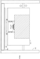
- Figure 1 shows a particularly preferred embodiment of an inkjet printing device in which the printing module 101 is adjusted to the repair position in order to ensure that the print head 103 can be replaced.
- the printing module 101 is adjustably attached to the positioning device 119 via adjustment devices 121.
- the positioning device 119 rests, for example, on a base plate 120.
- the at least one coupling means for the temporary fixation 113 preferably provided on the printing module 101 is attached to a support device 125, which itself merges into a superstructure 127.
- At least some of the electronic and mechanical components required for the proper operation of the print head 103 are housed in the superstructure 127.
- the fluid connections 115 are integrally connected to the fluid lines 118 for the supply/discharge of the ink.
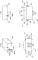
- Figure 2 shows the printing module 101, which is positioned in a working position in order to be able to print the medium 107 to be printed, which rests on the storage device 105.
- the print head 103 is Figure 1 shown again enlarged.
- This print head 103 comprises a base element 137, which has at least one row of nozzles (not shown in the drawing), an ink chamber 135 with two upward-facing fluidic counter-connections 115', which enable the circulation of ink through the ink chamber 135, a superstructure 139 comprising electrical contacts for the at least one row of nozzles and laterally arranged heating mats for the uniform heating of the ink chamber 135 (not shown in the drawing).
- the print head 103 comprises counter-device means 111' for the releasable fixation on the print module 103, counter-coupling means 113' for the temporary fixation on the print module 103 and exchange means 141 arranged on the base element 138, which can be used as an aid for exchanging the print head 103.
- the fluid-technical counter-connections 115' have sealing rings 131, which Prevent ink leakage when connecting the fluidic mating connections 115' to the corresponding fluidic connections 115.
- Figure 4 shows the print head 103 from Figure 3 in top view.
- a change tool 141 which comprises counter-change means 143.
- Counter-change means 143 are brought into mutual engagement with change means 133 attached to the base element 135 of the print head 103.
- Such a tool can be used as an aid when replacing the print head 103.
- the change tool 141 comprises an integrated fixing means 110A.
- Figure 6 shows a perspective view of the changing tool 141.
- an integrated fixing means 110A can be understood as a combination connection of a screw with a screw nut 110B on the interchangeable tool 141, wherein the screw is introduced through a simple hole on the interchangeable tool 141 and is releasably fixed to the interchangeable tool 141 by a screw/screw nut connection.
- the printing module 101 can be provided with at least one device means for the releasable fixation 111 and the printing head 103 with corresponding counter-device means 111', such that the printing head 103 is releasably fixed with fixing means 110 in the assembly step according to the above-mentioned step e).
- the printing module 101 is additionally provided with at least one coupling means for the temporary fixation 113 and the printing head 103 with corresponding counter-coupling means 113', such that the assembly step according to the above-mentioned step e) takes place in two steps, in that in a first step the printing head 103 is temporarily fixed to the at least one coupling means for the temporary fixation 113 before the printing head 103 is releasably fixed to the device means for the releasable fixation 111 with fixing means 110 in the second step.
- the print head 103 is provided with a change means 133 and, in addition, a change tool 141, which comprises counter-change means 143 and an integrated fixing means 110A, is provided, wherein the removal and/or insertion of the print head 103 takes place according to the corresponding steps c), d) in such a way that the change means 133 of the print head 103 are brought into engagement with the corresponding counter-change means 143 and, before the removal and/or after the insertion of the print head 103, the change tool 141 with the integrated fixing means 110A is releasably fixed to auxiliary device means provided on the front of the support frame 109 and is removed after the execution of steps c) and/or d).
- the fixing means 110 can be inserted at the front and/or rear into the device means provided for the releasable fixation 111 and the corresponding counter-device means 111' with a fixing tool 112.
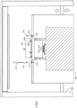
- Figure 7 shows a step of the replacement in which the printing module 103 is positioned in the repair position.
- the printing module 101 and its components in the figures are partly not shown to scale and/or enlarged and/or reduced.
Landscapes
- Ink Jet (AREA)
Description
- Die vorliegende Erfindung bezieht sich auf ein Druckmodul mit frontseitig auswechselbarem Druckkopf in einem Tintenstrahldrucker. (Siehe zum Beispiel
EP 506107 JP2013-248875 - Tintenstrahldrucker umfassen in der Regel ein Druckmodul und eine Positionierungseinrichtung, welche dazu ausgelegt ist das Druckmodul und ein Medium mit einer zu bedruckenden Oberfläche in vorbestimmter Weise bei konstantem Abstand des Druckmoduls von der Oberfläche in zwei Dimensionen relativ zueinander bewegen zu können. Das Druckmodul selbst weist mindestens einen Druckkopf auf mit mindestens einer Düsenreihe von nebeneinander angeordneten Düsen, über die Tinte auf die zu bedruckende Oberfläche aufgebracht werden kann. Das Bedrucken findet dabei durch den Ausstoss von Tintentropfen gemäss einer vorgegebenen gegebenenfalls variablen Druckfrequenz und Tropfenanzahl statt.
- Im Stand der Technik sind scannende Drucker und Single-Pass Drucker bekannt. Bei einem scannenden Drucker fährt ein scannendes Druckmodul in einem oder mehreren Pässen über eine Zeile eines zu bedruckenden Mediums, während dessen diese Zeile gedruckt wird. Das entsprechende Verfahren wird Scanverfahren genannt. Wird in einem Scanverfahren eine Zeile fertig bedruckt, so wird das zu bedruckende Medium um eine Zeile senkrecht zur vom Druckkopf ausgeführten Scanrichtung in eine Vorschubrichtung bewegt und das Bedrucken der nächsten Zeile kann beginnen.
- Bei einem Single-Pass-Drucker versteht man hingegen einen Drucker, der ein über das zu bedruckende Medium ortsfest positioniertes Druckmodul mit mindestens einem Druckkopf umfasst, wobei im entsprechenden Single-Pass-Verfahren das Medium in einem Betriebsmodus kontinuierlich bewegt wird und der mindestens eine Druckkopf das Medium ein einziges Mal erblickt, wobei der Druckkopf selbst am Druckmodul stationär angeordnet ist.
- Ein Druckmodul umfasst bekanntlich an der Frontseite einen Träger, der als Rahmen mit zumindest einer Öffnung ausgebildet ist, welche für die Aufnahme eines Druckkopfes vorgesehen ist und auf welchem Rahmen die Montage des Druckkopfes erfolgt, wobei bei den bekannten Druckmodulen der Rahmen den Druckkopf nur von der Oberseite des Druckmoduls, also nur rückseitig, empfangen kann. Am Rahmen selbst sind Justiervorrichtungen vorgesehen, mit denen der Druckkopf ausgerichtet werden kann. Eine Vielzahl an elektronischen und mechanischen Komponenten sind auf dem Rahmen und über den Druckkopf für den ordentlichen Betrieb des Druckkopfes vorgesehen.
- Um den gestiegenen Anforderungen der Platzeinsparung gerecht zu werden, wurden Druckmodule zunehmend kompakter gebaut. Von Vorteil ist dabei, dass neben der Platzeinsparung zusätzlich Materialkosten eingespart werden können. Eine Folge davon ist allerdings, dass Komponenten vielfach übereinander und insbesondere über die Druckköpfe eingebaut werden müssen.
- Je kompakter die Bauweise des Druckmoduls ist, desto eingeschränkter die Zugänglichkeit von deren Oberseite und entsprechend schwieriger und zeitintensiver gestaltet sich der Austausch eines Druckkopfes. Um den Austausch eines Druckkopfes im Reparaturfall trotzdem gewährleisten zu können, ist es notwendig zumindest ein Teil der im Druckmodul untergebrachten Komponenten auszubauen.
- Die kompakte Bauweise der Druckmodule erweist sich zwar als platzsparender und bei der Herstellung unter anderem als ressourcen-sparender, führt allerdings zu einer mangelnden Effizienz bei der Instandhaltung, da die Zugänglichkeit von deren Oberseite erschwert ist, sodass der Austausch eines Druckkopfes im Reparaturfall mit einem Vielfachen an Mehrarbeit verbunden ist. Die hierdurch erforderlichen Austausch-Maßnahmen kosten somit viel Zeit. Dies ist vor allem dann relevant wenn mehrere Druckköpfe an unterschiedlichen Stellen am Druckmodul ausgetauscht werden müssen.
- Ein den langsamen Austausch der Druckköpfe verursachendes Problem ist somit die Tatsache, dass bei den heute bekannten Druckmodulen lediglich das oben beschriebene Baukonzept für den Empfang des Druckkopfes verwirklicht ist.
- Es besteht daher der Bedarf nach einem Druckmodul und einem Verfahren mit dem der Austausch eines Druckkopfes an einem Druckmodul, trotz eingeschränkter Zugänglichkeit von der Oberseite, schnell und effizient bewerkstellgen werden kann.
Der vorliegenden Erfindung liegt somit die Aufgabe zugrunde ein Druckmodul und ein Verfahren anzugeben, mit dem trotz eingeschränkter Zugänglichkeit von der Oberseite, jederzeit ein rasch durchführbarer Austausch im Reparaturfall gewährleistet ist. - Die Aufgabe wird mit dem erfindungsgemäßen Druckmodul nach Anspruch 1, dem erfindungsgemässen Tintenstrahldrucker nach Anspruch 8 gelöst, indem der Austausch des Druckkopfes am Druckmodul frontseitig vorgesehen ist bzw. frontseitig erfolgt. Die Unteransprüche der jeweiligen Hauptansprüche beschreiben deren bevorzugte Varianten.
- Wenn im Rahmen dieser Beschreibung von "Frontseite" des Druckmoduls gesprochen wird, so ist damit die Seite des Druckmoduls gemeint, welche direkt auf eine Ablageeinrichtung für ein zu bedruckendes Medium blickt.
- Wenn in Rahmen dieser Beschreibung von "frontseitig empfangen " gesprochen wird, so ist damit eine frontseitige Einführung des Druckkopfes in den Träger gemeint.
Bis dato haben herkömmliche Druckmodule alle Eines gemeinsam und zwar sind diese baulich derart konzipiert, dass ein Druckkopf lediglich von der Oberseite des Druckmodul, also nur rückseitig am Träger empfangen und ausgetauscht werden kann. - Erfindungsgemäß wird ein Druckmodul bereitgestellt, nach Anspruch 1 ,umfassend unter Anderem eine an der Frontseite angeordenete Baugruppe für die Montage eines Druckkopfes in einem Tintenstrahldrucker, wobei das Druckmodul relativ zu einer Ablageeinrichtung beabstandet angeordnet ist und die Baugruppe einen Trägerrahmen mit einer Öffnung, die sich durch den Trägerrahmen erstreckt und für die Aufnahme/Abgabe des Druckkopfes vorgesehen ist, wobei die Baugruppe Mittel für die Montage des Druckkopfes aufweist, welche ein frontseitiges Empfangen desselben in einer Reparaturstellung des Druckmoduls relativ zur Ablageeinrichtung ermöglichen, wobei die Mittel für die Montage zumindest ein Einrichtungs-Mittel für die lösbare Fixierung und zusätzlich zumindest ein Kupplungs-Mittel für eine temporäre Fixierung des Druckkopfes umfassen, wobei am Druckkopf entsprechende Gegen-Einrichtungs-Mittel und Gegen-Kupplungs-Mittel vorgesehen sind, wobei die Kupplungs-Mittel so ausgebildet sind, dass sie ein frontseitiges Einführen des Druckkopfes entgegen der Schwerkraft-Richtung ermöglichen und dass ein an die Kupplungs-Mittel temporär fixierter Druckkopf so fixiert ist, dass der noch nicht mittels Fixiermittel an die Einrichtungs-Mittel lösbar fixierte Druckkopf, sich nicht allein durch die auf ihn nach unten wirkende Schwerkraft aus einer vorläufigen Montageposition löst, sondern erst durch eine äussere Krafteinwirkung von den Kupplungs-Mittel gelöst werden kann, wobei das Kupplungs-Mittel für eine temporäre Fixierung nach unten ausgerichtet ist und das entsprechende Gegen-Kupplungs-Mittel am Druckkopf nach oben ausgerichtet ist.
- Reparaturstellung kann heissen, dass der Abstand zwischen Druckmodul und Ablageeinrichtung vergrössert wurde, um eine frontseitige Entnahme zu erlauben. Es sind jedoch auch andere Varianten denkbar, wie zum Beispiel Ablage des Druckkopfes auf einer auf die Ablageeinrichtung aufgebrachte Auflage. Zum Einführen oder zur Entnahme des oder der Druckköpfe wird dann lediglich der Rest vom Druckmodul angenähert oder entfernt.
- Die Erfindung wird im Folgenden anhand der Figuren im Detail und beispielhaft beschrieben.
-
Figur 1 zeigt eine Seitenansicht einer besonders bevorzugten Ausführungsform des erfindungsgemässen Druckmoduls 101 in Reparaturstellung in einem Tintenstrahldrucker -
Figur 2 zeigt eine Seitenansicht der besonders bevorzugten Ausführungsform des erfindungsgemässen Druckmoduls 101 in Arbeitsstellung in einem Tintenstrahldrucker -
Figur 3 zeigt eine schematische Darstellung eines Druckkopfes 103 in Seitenansicht -
Figur 4 zeigt eine schematische Darstellung des Druckkopfes 103 in Draufsicht -
Figur 5 zeigt eine schematische Darstellung eines Wechselwerkzeugs 141 zum Austauschen des Druckkopfes 103 -
Figur 6 zeigt eine perspektivische Darstellung eines Wechselwerkzeugs 141 zum Austauschen des Druckkopfes 103 -
Figur 7 zeigt ein Verfahrensschritt einer bevorzugten Ausführungsform des erfindungsgemässen Verfahrens, bei dem das Druckmodul 101 in Reparaturstellung verstellt ist - Aus Übersichtlichkeeitsgründen wurden bei einigen Figuren Bezugszeichen weggelassen. Es wird jedoch darauf hingewiesen, dass ein Bezugszeichen eines Elements in einer Figur einem identen Element in einer anderen Figur zugewiesen werden kann.
- Wie in
Figur 1 gezeigt umfasst das erfindungsgemässe Druckmodul 101 eine an der Frontseite angeordenete Baugruppe für die Montage eines Druckkopfes 103 in einem Tintenstrahldrucker, wobei das Druckmodul 101 relativ zu einer Ablageeinrichtung 105 beabstandet angeordnet ist und die Baugruppe einen Trägerrahmen 109 mit einer Öffnung, die sich durch den Trägerrahmen 109 erstreckt und für die Aufnahme/Abgabe des Druckkopfes 103 vorgesehen ist dadurch gekennzeichnet, dass die Baugruppe Mittel für die Montage des Druckkopfes 103 aufweist, welche ein frontseitiges Empfangen desselben in einer Reparaturstellung des Druckmoduls 101 relativ zur Ablageeinrichtung 105 ermöglichen. - Bevorzugte Ausführungen des erfindungsgemäßen Druckmoduls 101 werden im Folgenden einzeln angeführt. Die
Figuren 1 bis 3 stellen eine besonders bevorzugte Ausführungsform einer erfindungsgemässen Tintenstrahldruckvorrichtung dar, in der die im Folgenden einzeln angeführten Ausführungen als Kombination verwirklicht sind. - Am Druckmodul 101 können in einer bevorzugten Ausführungsform die Mittel für die Montage zumindest ein Einrichtungs-Mittel für die lösbare Fixierung 111 umfassen. Am Druckkopf 103 sind entsprechende Gegen-Einrichtungs-Mittel 111' vorgesehen.
- Die Mittel für die Montage können zusätzlich zu den Einrichtungs-Mittel für die lösbare Fixierung 111 zumindest ein Kupplungs-Mittel für eine temporäre Fixierung 113 umfassen, wobei am Druckkopf 103 entsprechende Gegen-Kupplungs-Mittel 113' vorgesehen sind.
- Eine temporäre Fixierung des Druckkopfes 103 an Kupplungs-Mittel 113 des Druckmoduls 101 gewährleistet, dass der noch nicht mittels Fixiermittel 110 an die Einrichtungs-Mittel 111 lösbar fixierte Druckkopf 103 sich nicht allein durch die auf den Druckkopf 103 nach unten wirkende Schwerkraft aus der (vorläufigen) Montageposition löst. Erst durch eine äussere Krafteinwirkung kann ein derart temporär fixiertes Druckkopf 103 von den Kupplungs-Mittel 111 gelöst werden. Derartige Kupplungsmittel für die temporäre Fixierung 113 können beispielsweise vorteilhaft eingesetzt werden, falls ein Druckkopf 103 an einer eher schwierig erreichbaren Position am Druckmodul 101 montiert werden muss, da problemlos einhändig gearbeitet werden kann.
- Die Einrichtungs-Mittel für die lösbare Fixierung 111 und das entsprechende Gegen-Einrichtungs-Mittel 111' können in einer bevorzugten Ausgestaltung als Gegenstück für ein Fixiermittel 110 vorgesehen sein, welches Fixiermittel 110 als Schraubvorrichtungs-Element ausgebildet sein kann bzw. das Kupplungs-Mittel für eine temporäre Fixierung 113 kann als elektrisches Anschluss-Element, insbesondere als Leiterplatten-Steckverbinder (Buchse oder Stecker) ausgebildet sein.
- Das verwirklichte Kupplungs-Mittel für eine temporäre Fixierung 113 ist dabei vorzugsweise nach unten ausgerichtet und das entsprechende Gegen-Kupplungs-Mittel 113' am Druckkopf 103 nach oben ausgerichtet.
- Die Baugruppe kann in einer weiteren bevorzugten Ausführungsform zumindest einen fluidtechnischen Anschluss 115 für die Zuführung und/oder Abführung von Tinte umfassen, wobei am Druckkopf 103 die entsprechende fluidtechnischen Gegen-Anschlüsse 115' vorgesehen sind.
- In einer ganz besonders bevorzugten Ausführungsform des erfindungsgemässen Druckmoduls 101 wird der zumindest eine fluidtechnische Anschluss 115 und das zumindest eine Kupplungs-Mittel für die temporäre Fixierung 113 schwimmend gehaltert. Eine derartige Ausführungsform ist ist insbesondere dann von Vorteil, wenn eine sehr genaue Positionierung des Druckkopes 103 in der Baugruppe in einem Positionierungsschritt ermöglicht und erzielt werden soll.
- Der zumindest eine fluidtechnische Anschluss 115 und das zumindest eine Kupplungs-Mittel für die temporäre Fixierung 113 können dergestalt angeordnet sein, dass eine gleichzeitige Kupplung/Entkupplung der jeweiligen Anschlüsse vorgesehen ist.
- Der zumindest eine fluidtechnische Anschluss 115 kann eine automatische Verschlussvorrichtung 117 aufweisen, sodass bei der Entkupplung des fluidtechnischen Anschlusses 115 ein Austreten der Tinte vermeidbar ist. Dies ist besonders vorteilhaft, da somit die Ablageeinrichtung 115 beim Austauschen des Druckkopfes 103 nicht mit Tinte beschmutzt wird.
- Das Druckmodul 103 kann in einer weiteren bevorzugten Ausführungsform voreingestellte Mittel zur automatischen Ausrichtung des Druckkopfes 103 umfassen, wobei diese derart angepasst sein können, dass diese den Druckkopf 103 gegen zwei an zwei Seitenflanken einer Kante des Trägerrahmens 109 angeordnete Exzenter drücken, wenn der Druckkopf 103 in der Baugruppe montiert ist.
- Der erfindungsgemässe Tintenstrahldrucker umfasst das erfindungsgemässe Druckmodul 101 in einer Ausführungsform, in der auch die oben skizziierten bevorzugten Elemente verwirklicht sein können und eine Positionierungseinrichtung 119, welche dazu ausgelegt ist, den Abstand des Druckmoduls 101 relativ zu einer Ablageeinrichtung 105 für ein zu bedruckendes Medium 107 verändern zu können, wobei mit der Positionierungseinrichtung 119 das Druckmodul 101 zwischen einer Arbeitsstellung und einer Reparaturstellung verstellbar ist und beim Bedrucken des zu bedruckenden Mediums 107 das Druckmodul 101 in der Arbeitsstellung relativ zur Ablageeinrichtung 105 innerhalb einem ersten Distanzintervall positionierbar ist, und beim Austauschen des Druckkopfes 103 das Druckmodul 101 in der Reparaturstellung relativ zur Ablageeinrichtung 105 innerhalb eines zweiten Distanzintervalls positionierbar ist.
- In einer bevorzugten Ausgestaltung des erfindungsgemässen Tintenstrahldruckers entspricht die minimale Distzanz des zweiten Distanzintervalls in der Reparaturstellung mindestens der Höhe des Druckkopfes 103.
-
Figur 1 zeigt eine besonders bevorzugte Ausführungsform einer Tintenstrahldruckvorrichtung, in der das Druckmodul 101 in Reparaturstellung verstellt ist, um den Austausch des Druckkopfes 103 gewährleisten zu können. Das Druckmodul 101 ist dabei über Verstelleinrichtungen 121 an die Positionierungseinrichtung 119 verstellbar befestigt. Die Positionierungseinrichtung 119 liegt zum Beispiel an einer Bodenplatte 120 auf. Die am Druckmodul 101 bevorzugt vorgesehene zumindest eine Kupplungs-Mittel für die temporäre Fixierung 113 ist an einer Trageinrichtung 125 befestigt, die selbst in einem Überbau 127 übergeht. Im Überbau 127 ist zumindest ein Teil der elektronischen und mechanischen Komponenten untergebracht, die für den ordentlichen Betrieb des Druckkopfes 103 erforderlich sind. Die fluidtechnischen Anschlüsse 115 sind in diesem Beispiel einstückig mit den fluidtechnischen Leitungen 118 für die Zuführung/Abführung der Tinte verbunden. -
Figur 2 zeigt hingegen das Druckmodul 101, welches in einer Arbeitsstellung positioniert ist, um das zu bedruckende Medium 107, welches auf die Ablageeinrichtung 105 aufliegt, bedrucken zu können. - In
Figur 3 ist der Druckkopf 103 ausFigur 1 nochmals vergrössert dargestellt. Dieser Druckkopf 103 umfasst ein Bodenelement 137, welches zumindest eine Düsenreihe aufweist (in der Zeichnung nicht dargestellt), eine Tinten-Kammer 135 mit zwei nach oben gerichteten fluidtechnischen Gegen-Anschlüssen 115', die die Zirkulation von Tinte durch die Tinten-Kammer 135 ermöglichen, einen Oberbau 139 umfassend elektrische Kontaktierungen für die zumindest eine Düsenreihe und seitlich angeordnete Heizmatten für die gleichmässige Erwärmung der Tinten-Kammer 135 (in der Zeichnung nicht dargestellt). Zusätzlich umfasst der Druckkopf 103 Gegen-Einrichtungs-Mittel 111' für die lösbare Fixierung am Druckmodul 103, Gegen-Kupplungs-Mittel 113' für die temporäre Fixierung am Druckmodul 103 und am Bodenelement 138 angeordnete Wechselmittel 141, die als Hilfsmittel zum Austauschen des Druckkopfes 103 zum Einsatz kommen können. Die fluidtechnischen Gegen-Anschlüsse 115' weisen Dichtringe 131 auf, die ein Austreten von Tinte beim Verbinden der fluidtechnischen Gegen-Anschlüsse 115' mit den entsprechenden fluidtechnischen Anschlüsse 115 verhindern. -
Figur 4 zeigt den Druckkopf 103 ausFigur 3 in Draufsicht. - In
Figur 5 ist ein Wechselwerkzeug 141 dargestellt, welches Gegen-Wechsel-Mittel 143 umfasst. Gegen-Wechsel-Mittel 143 werden mit am Bodenelement 135 des Druckkopfes 103 angebrachten Wechselmittel 133 im gegenseitigen Eingriff gebracht. Ein derartiges Werkzeug kann als Hilfsmittel beim Austauschen des Druckkkopfes 103 verwendet werden. Zusätzlich umfasst das Wechselwerkzeug 141 ein integriertes Fixiermittel 110A.Figur 6 zeigt eine perspektivische Darstellungdes des Wechselwerkzeugs 141. - Unter einem integrierten Fixiermittel 110A kann im Rahmen der Beschreibung eine Kombinationsverbindung einer Schraube mit einer Schraubmutter 110B am Wechselwerkzeug 141 verstanden werden, wobei die Schraube durch eine einfache Bohrung am Wechselwerkzeug 141 eingebracht ist und durch eine Schraub/Schraubmutter Verbindung am Wechselwerkzeug 141 lösbar fixiert ist.
- Das erfindungsgemässe Verfahren zur Montage oder zum Auswechseln eines Druckkopfes 103 an einem Druckmodul 101 in einem erfindungsgemässen Tintenstrahldrucker, bei dem an der Frontseite des Druckmoduls 101 eine Baugruppe bereitgestellt wird, umfasst folgende Schritte:
- a) Verfahren des Druckmoduls 101 in eine Reparaturstellung
- b) Falls bereits ein Druckkopf 103 in der Baugruppe montiert ist, Entfernung der Mittel für die Montage des Druckkopfes 103
- c) Entnahme des Druckkopfes 103
- d) Einführung eines neuen Druckkopfes 103 in die Baugruppe
- e) Montage des Druckkopfes 103 in der Baugruppe mit Mittel für die Montage,
- Im Verfahren kann das Druckmodul 101 mit zumindest einem Einrichtungs-Mittel für die lösbare Fixierung 111 und der Druckkopf 103 mit entsprechenden Gegen-Einrichtungs-Mittel 111' bereitgestellt werden, dergestalt, dass der Druckkopf 103 im Montageschritt gemäss dem oben genannten Schritt e) mit Fixiermittel 110 lösbar fixiert wird.
- In einem bevorzugten Verfahren wird das Druckmodul 101 zusätzlich mit zumindest einem Kupplungsmittel für die temporäre Fixierung 113 und der Druckkopf 103 mit entsprechenden Gegen-Kupplungs-Mittel 113' bereitgestellt, dergestalt, dass der Montageschritt gemäss dem oben genannten Schritt e) über zwei Schritte erfolgt, indem in einem ersten Schritt der Druckkopf 103 an das zumindest eine Kupplungs-Mittel für die temporäre Fixierung 113 temporär fixiert wird bevor der Druckkopf 103 im zweiten Schritt an die Einrichtungs-Mittel für die lösbar Fixierung 111 mit Fixiermittel 110 lösbar fixiert wird.
- In einem weiteren bevorzugten Verfahren wird der Druckkopf 103 mit Wechselmittel 133 bereitgestellt und zusätzlich wird ein Wechselwerkzeug 141, welches Gegen-Wechselmittel 143 und ein integriertes Fixiermittel 110A umfasst, bereitgestellt, wobei die Entnahme und/oder die Einführung des Druckkopfes 103 gemäss den entsprechenden Schritten c), d) dergestalt erfolgt, dass die Wechselmittel 133 des Druckkopfes 103 mit den entsprechenden Gegen-Wechselmittel 143 in Eingriff gebracht werden und vor der Entnahme und/oder nach der Einführung des Druckkopfes 103 das Wechselwerkzeug 141 mit dem integrierten Fixiermittel 110A an frontseitig am Trägerrahmen 109 vorgesehene Hilfs-Einrichtungs-Mittel lösbar fixiert wird und nach der Ausführung der Schritte c) und/oder d) entfernt wird.
- Das Fixierungsmittel 110 kann frontseitig und/oder rückseitig in die dafür vorgesehenen Einrichtungs-Mittel für die lösbare Fixierung 111 und die entsprechenden Gegen-Einrichtungs-Mittel 111' mit einem Fixierwerkzeug 112 erfolgen.
-
Figur 7 zeigt ein Schritt des Austausches, bei dem das Druckmodul 103 in der Reparaturstellung positioniert ist. - Der Ordnung halber wird abschliessend darauf hingewiesen, dass zum besseren Verständnis das Druckmodul 101 und dessen Bestandteile in den Figuren teilweise nicht maßstäblich und/oder vergrößert und/oder verkleinert dargestellt wurden.
Claims (9)
- Druckmodul (101) umfassend eine an der Frontseite angeordenete Baugruppe für die Montage eines Druckkopfes (103) in einem Tintenstrahldrucker, wobei das Druckmodul (101) relativ zu einer Ablageeinrichtung (105) beabstandet angeordnet ist und die Baugruppe einen Trägerrahmen (109) mit einer Öffnung, die sich durch den Trägerrahmen (109) erstreckt und für die Aufnahme/Abgabe des Druckkopfes (103) vorgesehen ist, wobei die Baugruppe Mittel für die Montage des Druckkopfes (103) aufweist, welche ein frontseitiges Einführen und eine frontseitige Entnahme desselben in einer Reparaturstellung des Druckmoduls (101) relativ zur Ablageeinrichtung (105) ermöglichen, wobei die Mittel für die Montage zumindest ein Einrichtungs-Mittel für die lösbare Fixierung (111) und zusätzlich zumindest ein Kupplungs-Mittel (113) für eine temporäre Fixierung (113) des Druckkopfes (103) umfassen, wobei am Druckkopf (103) entsprechende Gegen-Einrichtungs-Mittel (111') und Gegen-Kupplungs-Mittel (113') vorgesehen sind, dadurch gekennzeichnet, dass die Kupplungs-Mittel (113) so ausgebildet sind, dass sie ein frontseitiges Einführen des Druckkopfes entgegen der Schwerkraft-Richtung ermöglichen und dass ein an die Kupplungs-Mittel (113) temporär fixierter Druckkopf (103) so fixiert ist, dass der noch nicht mittels Fixiermittel (110) an die Einrichtungs-Mittel (111) lösbar fixierte Druckkopf (103), sich nicht allein durch die auf ihn nach unten wirkende Schwerkraft aus einer vorlaufigen Montageposition löst, sondern erst durch eine äussere Krafteinwirkung von den Kupplungs-Mittel (113) gelöst werden kann, wobei das Kupplungs-Mittel für eine temporäre Fixierung (113) nach unten ausgerichtet ist und das entsprechende Gegen-Kupplungs-Mittel (113') am Druckkopf (103) nach oben ausgerichtet ist.
- Druckmodul (101) nach Anspruch 1 dadurch gekennzeichnet, dass das Einrichtungs-Mittel für die lösbar Fixierung (111) und das entsprechende Gegen-Einrichtungsmittel (111') jeweils als Gegenstück für ein Fixiermittel (110) vorgesehen sind, welches Fixiermittel (110) als Schraubvorrichtungs-Element ausgebildet sein kann bzw. das Kupplungs-Mittel für die temporäre Fixierung (113) als elektrisches Anschluss-Element, insbesondere als Leiterplatten-Steckverbinder (Buchse oder Stecker) ausgebildet ist.
- Druckmodul (101) nach Ansprcuh 1 oder 2 dadurch gekennzeichnet, dass die Baugruppe zumindest einen fluidtechnischen Anschluss (115) für die Zuführung und/oder Abführung von Tinte umfasst, wobei am Druckkopf (103) entsprechende fluidtechnische Gegen-Anschlüsse (115') vorgesehen sind.
- Druckmodul (101) nach zumindest eines der Ansprüche 1 bis 3 dadurch gekennzeichnet, dass der zumindest eine fluidtechnische Anschluss (115) und das zumindest eine Kupplungs-Mittel für die temporäre Fixierung (113) schwimmend gehaltert werden.
- Druckmodul (101) nach Anspruch 3 oder 4 dadurch gekennzeichnet, dass der zumindest eine fluidtechnische Anschluss (115) und das zumindest eine Kupplungs-Mittel für die temporäre Fixierung (113) dergestalt angeordnet sind, dass eine gleichzeitige Kupplung/Entkupplung der jeweiligen Anschlüsse vorgesehen ist.
- Druckmodul (101) nach zumindest eines der Ansprüche 3 bis 4 dadurch gekennzeichnet, dass der zumindest eine fluidtechnische Anschluss (115) eine automatische Verschtussvorrichtung (117) aufweist, sodass bei der Entkupplung des zumindest einen fluidtechnischen Anschlusses (115) ein Austreten der Tinte vermeidbar ist.
- Druckmodul (101) nach zumindest eines der vorangehenden Ansprüche dadurch gekennzeichnet, dass das Druckmodul (103) voreingestellte Mittel zur automatischen Ausrichtung des Druckkopfes (103) umfasst, wobei diese derart angepasst sind, dass diese den Druckkopf (103) gegen zwei an zwei Seitenflanken einer Kante des Trägerrahmens (109) angeordnete Exzenter drücken, wenn der Druckkopf (103) in der Baugruppe montiert ist.
- Tintenstrahldrucker umfassend ein Druckmodul (101) nach zumindest einem der Ansprüche 1 bis 7 und eine Positionierungseinrichtung (119), welche dazu ausgelegt ist den Abstand des Druckmoduls (101) relativ zu einer Ablageeinrichtung (105) für ein zu bedruckendes Medium (107) verändern zu können dadurch gekennzeichnet, dass mit der Positionierungseinrichtung (119) das Druckmodul (101) zwischen einer Arbeitsstellung und einer Reparaturstellung verstellbar ist und beim Bedrucken des zu bedruckenden Mediums (107) das Druckmodul (101) in der Arbeitsstellung relativ zur Ablageeinrichtung (105) innerhalb einem ersten Distanzintervall positionierbar ist, und beim Austauschen des Druckkopfes (103) das Druckmodul (101) in der Reparaturstellung relativ zur Ablageeinrichtung (105) innerhalb eines zweiten Distanzintervalls positionierbar ist.
- Tintenstrahldrucker nach Anspruch 8 dadurch gekennzeichnet, dass in der Reparaturstellung die minimale Distzanz des zweiten Distanzintervalls mindestens der Höhe des Druckkopfes (103) entspricht.
Applications Claiming Priority (3)
| Application Number | Priority Date | Filing Date | Title |
|---|---|---|---|
| DE102014011882.7A DE102014011882A1 (de) | 2014-08-13 | 2014-08-13 | Druckmodul mit frontseitig auswechselbarem Druckkopf |
| ITBZ20140035 | 2014-09-16 | ||
| PCT/EP2015/001557 WO2016023620A1 (de) | 2014-08-13 | 2015-07-29 | Druckmodul mit frontseitig auswechselbarem druckknopf |
Publications (3)
| Publication Number | Publication Date |
|---|---|
| EP3180195A1 EP3180195A1 (de) | 2017-06-21 |
| EP3180195B1 EP3180195B1 (de) | 2020-06-24 |
| EP3180195B2 true EP3180195B2 (de) | 2024-05-08 |
Family
ID=53765181
Family Applications (1)
| Application Number | Title | Priority Date | Filing Date |
|---|---|---|---|
| EP15744881.2A Active EP3180195B2 (de) | 2014-08-13 | 2015-07-29 | Druckmodul mit frontseitig auswechselbarem druckkopf |
Country Status (4)
| Country | Link |
|---|---|
| US (1) | US10071548B2 (de) |
| EP (1) | EP3180195B2 (de) |
| ES (1) | ES2819510T3 (de) |
| WO (1) | WO2016023620A1 (de) |
Families Citing this family (2)
| Publication number | Priority date | Publication date | Assignee | Title |
|---|---|---|---|---|
| ES2640064B2 (es) * | 2016-04-29 | 2018-02-27 | Tecglass Sl | Carro, máquina y procedimiento de impresión digital sobre vidrio con módulos extraíbles |
| WO2023232328A1 (en) * | 2022-06-02 | 2023-12-07 | Memjet Technology Limited | Tandem print modules with interstitial bar for optimizing airflow |
Citations (1)
| Publication number | Priority date | Publication date | Assignee | Title |
|---|---|---|---|---|
| US20130314469A1 (en) † | 2010-07-22 | 2013-11-28 | Yuan Chang | Printhead mounting and adjusting mechanism for inkjet printer |
Family Cites Families (13)
| Publication number | Priority date | Publication date | Assignee | Title |
|---|---|---|---|---|
| DE69220273T2 (de) | 1991-03-28 | 1998-01-22 | Canon Kk | Bogenfördergerät für eine Aufzeichnungsvorrichtung |
| JP3800995B2 (ja) * | 2001-06-26 | 2006-07-26 | ブラザー工業株式会社 | インクジェット記録装置 |
| US6471335B1 (en) * | 2001-08-06 | 2002-10-29 | Creo Inc. | Method for mutual spatial registration of inkjet cartridges |
| DE10164527A1 (de) | 2001-12-15 | 2003-07-10 | Francotyp Postalia Ag | Anordnung zum Schutz eines Druckmoduls in einem Postverarbeitungsgerät |
| JP4415663B2 (ja) | 2003-12-12 | 2010-02-17 | ソニー株式会社 | 液体吐出装置 |
| GB0502440D0 (en) * | 2005-02-07 | 2005-03-16 | Xaar Technology Ltd | Printing machines |
| AT501432B1 (de) | 2005-02-08 | 2008-04-15 | Durst Phototech Digital Tech | Tintenstrahldruckvorrichtung und verfahren zum drucken von mehrfarbigen bildern |
| US7533976B2 (en) | 2005-04-27 | 2009-05-19 | Hewlett-Packard Development Company, L.P. | Sealing component defining first, second, and third seals |
| JP5194639B2 (ja) * | 2007-08-22 | 2013-05-08 | セイコーエプソン株式会社 | 液体噴射ヘッド用のメンテナンス装置及び液体噴射装置 |
| DE102010037829A1 (de) | 2010-09-28 | 2012-03-29 | OCé PRINTING SYSTEMS GMBH | Druckwerk für ein Tintendruckgerät |
| JP2012111098A (ja) | 2010-11-24 | 2012-06-14 | Seiko Epson Corp | 液体噴射ヘッドユニット、および、その製造方法 |
| JP5928674B2 (ja) | 2011-01-14 | 2016-06-01 | セイコーエプソン株式会社 | 液体噴射ヘッドユニット及び液体噴射装置 |
| JP6119173B2 (ja) | 2012-05-02 | 2017-04-26 | セイコーエプソン株式会社 | 液体噴射ヘッドモジュール及び液体噴射装置 |
-
2015
- 2015-07-29 WO PCT/EP2015/001557 patent/WO2016023620A1/de active Application Filing
- 2015-07-29 ES ES15744881T patent/ES2819510T3/es active Active
- 2015-07-29 US US15/502,529 patent/US10071548B2/en active Active
- 2015-07-29 EP EP15744881.2A patent/EP3180195B2/de active Active
Patent Citations (1)
| Publication number | Priority date | Publication date | Assignee | Title |
|---|---|---|---|---|
| US20130314469A1 (en) † | 2010-07-22 | 2013-11-28 | Yuan Chang | Printhead mounting and adjusting mechanism for inkjet printer |
Also Published As
| Publication number | Publication date |
|---|---|
| EP3180195B1 (de) | 2020-06-24 |
| ES2819510T3 (es) | 2021-04-16 |
| WO2016023620A1 (de) | 2016-02-18 |
| EP3180195A1 (de) | 2017-06-21 |
| WO2016023620A8 (de) | 2017-05-11 |
| US20170232769A1 (en) | 2017-08-17 |
| US10071548B2 (en) | 2018-09-11 |
Similar Documents
| Publication | Publication Date | Title |
|---|---|---|
| EP1725362B1 (de) | Verfahren und fertigungseinrichtung zur herstellung einer geteilten lageranordnung | |
| DE3502901A1 (de) | Fluessigkeitsstrahl-aufzeichnungsgeraet | |
| DE102013110731B3 (de) | Trennstreifen-Anordnung für Lötdüse, sowie Lötdüseneinrichtung zum selektiven Wellenlöten | |
| EP3180195B2 (de) | Druckmodul mit frontseitig auswechselbarem druckkopf | |
| EP3463903A1 (de) | Reinigungskopf sowie vorrichtung und verfahren zur reinigung von druckköpfen | |
| EP2346689B1 (de) | Drucktischanordnung | |
| DE10331275A1 (de) | Befestigungs- oder Einbauvorrichtung für ein fahrzeugseitiges Teil | |
| EP0086954B1 (de) | Werkzeug zum Herausziehen eines Elektronikeinschubes aus einem Haltegestell | |
| WO2018041705A1 (de) | Vorrichtung und verfahren zum fügen einer lichtscheibe mit einem gehäuse einer beleuchtungseinrichtung eines kraftfahrzeugs | |
| DE202010015351U1 (de) | Vorrichtung zur Absenkung, Positionierung und Anhebung von Druckelementen eines Druckergeräts | |
| DE102014011882A1 (de) | Druckmodul mit frontseitig auswechselbarem Druckkopf | |
| AT508950B1 (de) | Kühleinrichtung für ein rändelwerkzeug | |
| AT407060B (de) | Vorrichtung zum wechseln der nadelbretter einer nadelmaschine | |
| DE102014110278A1 (de) | Halterahmen für Steckverbindermodule und/oder Steckverbinder | |
| DE69937096T2 (de) | Mechanismus zum installieren und halten eines durckkopfs | |
| DE102019123099B3 (de) | Vorrichtung und Verfahren zum Herstellen von Schaltmodulen mit einem Gehäuse und zumindest einer darin eingeführten Elektronikkomponente | |
| EP3996927A1 (de) | Drucker zum bedrucken von plattenartigen druckmedien, säuberungseinrichtung für den drucker sowie verfahren zum warten des druckers | |
| EP3733420B1 (de) | Druckkopfmodul und testdrucksystem | |
| EP3490805B1 (de) | Vorrichtung und verfahren zum justieren von druckköpfen | |
| DE102019006362A1 (de) | Vorrichtung zum Zuführen eines Mediums zu einem Werkzeug einer Bearbeitungsmaschine und Verfahren zum Bereitstellen einer derartigen Vorrichtung | |
| DE202012000263U1 (de) | Drucksystem | |
| WO2012062431A1 (de) | Kühlmittelkreis für ein brennstoffzellensystem und verfahren zum fluidischen koppeln eines ionenaustauschermoduls mit einer komponente eines kühlmittelkreises | |
| DE102020128910A1 (de) | Haltevorrichtung zur Befestigung einer elektrischen Baugruppe an einem Druckkopf und eine entsprechende Druckkopf-Anordnung | |
| DE102018200609A1 (de) | Vorrichtung zum Ausrichten von Druckköpfen | |
| EP4181639A1 (de) | Vorrichtungen und verfahren zur montage einer mehrfachanzeigebaugruppe |
Legal Events
| Date | Code | Title | Description |
|---|---|---|---|
| STAA | Information on the status of an ep patent application or granted ep patent |
Free format text: STATUS: THE INTERNATIONAL PUBLICATION HAS BEEN MADE |
|
| PUAI | Public reference made under article 153(3) epc to a published international application that has entered the european phase |
Free format text: ORIGINAL CODE: 0009012 |
|
| STAA | Information on the status of an ep patent application or granted ep patent |
Free format text: STATUS: REQUEST FOR EXAMINATION WAS MADE |
|
| 17P | Request for examination filed |
Effective date: 20170313 |
|
| AK | Designated contracting states |
Kind code of ref document: A1 Designated state(s): AL AT BE BG CH CY CZ DE DK EE ES FI FR GB GR HR HU IE IS IT LI LT LU LV MC MK MT NL NO PL PT RO RS SE SI SK SM TR |
|
| AX | Request for extension of the european patent |
Extension state: BA ME |
|
| DAV | Request for validation of the european patent (deleted) | ||
| DAX | Request for extension of the european patent (deleted) | ||
| RAP1 | Party data changed (applicant data changed or rights of an application transferred) |
Owner name: DURST PHOTOTECHNIK AG |
|
| GRAP | Despatch of communication of intention to grant a patent |
Free format text: ORIGINAL CODE: EPIDOSNIGR1 |
|
| STAA | Information on the status of an ep patent application or granted ep patent |
Free format text: STATUS: GRANT OF PATENT IS INTENDED |
|
| INTG | Intention to grant announced |
Effective date: 20200220 |
|
| GRAS | Grant fee paid |
Free format text: ORIGINAL CODE: EPIDOSNIGR3 |
|
| GRAA | (expected) grant |
Free format text: ORIGINAL CODE: 0009210 |
|
| STAA | Information on the status of an ep patent application or granted ep patent |
Free format text: STATUS: THE PATENT HAS BEEN GRANTED |
|
| AK | Designated contracting states |
Kind code of ref document: B1 Designated state(s): AL AT BE BG CH CY CZ DE DK EE ES FI FR GB GR HR HU IE IS IT LI LT LU LV MC MK MT NL NO PL PT RO RS SE SI SK SM TR |
|
| REG | Reference to a national code |
Ref country code: GB Ref legal event code: FG4D Free format text: NOT ENGLISH |
|
| REG | Reference to a national code |
Ref country code: CH Ref legal event code: EP |
|
| REG | Reference to a national code |
Ref country code: AT Ref legal event code: REF Ref document number: 1283498 Country of ref document: AT Kind code of ref document: T Effective date: 20200715 |
|
| REG | Reference to a national code |
Ref country code: DE Ref legal event code: R096 Ref document number: 502015012871 Country of ref document: DE |
|
| REG | Reference to a national code |
Ref country code: IE Ref legal event code: FG4D Free format text: LANGUAGE OF EP DOCUMENT: GERMAN |
|
| PG25 | Lapsed in a contracting state [announced via postgrant information from national office to epo] |
Ref country code: LT Free format text: LAPSE BECAUSE OF FAILURE TO SUBMIT A TRANSLATION OF THE DESCRIPTION OR TO PAY THE FEE WITHIN THE PRESCRIBED TIME-LIMIT Effective date: 20200624 Ref country code: FI Free format text: LAPSE BECAUSE OF FAILURE TO SUBMIT A TRANSLATION OF THE DESCRIPTION OR TO PAY THE FEE WITHIN THE PRESCRIBED TIME-LIMIT Effective date: 20200624 Ref country code: GR Free format text: LAPSE BECAUSE OF FAILURE TO SUBMIT A TRANSLATION OF THE DESCRIPTION OR TO PAY THE FEE WITHIN THE PRESCRIBED TIME-LIMIT Effective date: 20200925 Ref country code: NO Free format text: LAPSE BECAUSE OF FAILURE TO SUBMIT A TRANSLATION OF THE DESCRIPTION OR TO PAY THE FEE WITHIN THE PRESCRIBED TIME-LIMIT Effective date: 20200924 Ref country code: SE Free format text: LAPSE BECAUSE OF FAILURE TO SUBMIT A TRANSLATION OF THE DESCRIPTION OR TO PAY THE FEE WITHIN THE PRESCRIBED TIME-LIMIT Effective date: 20200624 |
|
| REG | Reference to a national code |
Ref country code: LT Ref legal event code: MG4D |
|
| PG25 | Lapsed in a contracting state [announced via postgrant information from national office to epo] |
Ref country code: BG Free format text: LAPSE BECAUSE OF FAILURE TO SUBMIT A TRANSLATION OF THE DESCRIPTION OR TO PAY THE FEE WITHIN THE PRESCRIBED TIME-LIMIT Effective date: 20200924 Ref country code: LV Free format text: LAPSE BECAUSE OF FAILURE TO SUBMIT A TRANSLATION OF THE DESCRIPTION OR TO PAY THE FEE WITHIN THE PRESCRIBED TIME-LIMIT Effective date: 20200624 Ref country code: RS Free format text: LAPSE BECAUSE OF FAILURE TO SUBMIT A TRANSLATION OF THE DESCRIPTION OR TO PAY THE FEE WITHIN THE PRESCRIBED TIME-LIMIT Effective date: 20200624 Ref country code: HR Free format text: LAPSE BECAUSE OF FAILURE TO SUBMIT A TRANSLATION OF THE DESCRIPTION OR TO PAY THE FEE WITHIN THE PRESCRIBED TIME-LIMIT Effective date: 20200624 |
|
| REG | Reference to a national code |
Ref country code: NL Ref legal event code: MP Effective date: 20200624 |
|
| PG25 | Lapsed in a contracting state [announced via postgrant information from national office to epo] |
Ref country code: AL Free format text: LAPSE BECAUSE OF FAILURE TO SUBMIT A TRANSLATION OF THE DESCRIPTION OR TO PAY THE FEE WITHIN THE PRESCRIBED TIME-LIMIT Effective date: 20200624 Ref country code: NL Free format text: LAPSE BECAUSE OF FAILURE TO SUBMIT A TRANSLATION OF THE DESCRIPTION OR TO PAY THE FEE WITHIN THE PRESCRIBED TIME-LIMIT Effective date: 20200624 |
|
| PG25 | Lapsed in a contracting state [announced via postgrant information from national office to epo] |
Ref country code: SM Free format text: LAPSE BECAUSE OF FAILURE TO SUBMIT A TRANSLATION OF THE DESCRIPTION OR TO PAY THE FEE WITHIN THE PRESCRIBED TIME-LIMIT Effective date: 20200624 Ref country code: EE Free format text: LAPSE BECAUSE OF FAILURE TO SUBMIT A TRANSLATION OF THE DESCRIPTION OR TO PAY THE FEE WITHIN THE PRESCRIBED TIME-LIMIT Effective date: 20200624 Ref country code: RO Free format text: LAPSE BECAUSE OF FAILURE TO SUBMIT A TRANSLATION OF THE DESCRIPTION OR TO PAY THE FEE WITHIN THE PRESCRIBED TIME-LIMIT Effective date: 20200624 Ref country code: CZ Free format text: LAPSE BECAUSE OF FAILURE TO SUBMIT A TRANSLATION OF THE DESCRIPTION OR TO PAY THE FEE WITHIN THE PRESCRIBED TIME-LIMIT Effective date: 20200624 Ref country code: PT Free format text: LAPSE BECAUSE OF FAILURE TO SUBMIT A TRANSLATION OF THE DESCRIPTION OR TO PAY THE FEE WITHIN THE PRESCRIBED TIME-LIMIT Effective date: 20201026 |
|
| PG25 | Lapsed in a contracting state [announced via postgrant information from national office to epo] |
Ref country code: SK Free format text: LAPSE BECAUSE OF FAILURE TO SUBMIT A TRANSLATION OF THE DESCRIPTION OR TO PAY THE FEE WITHIN THE PRESCRIBED TIME-LIMIT Effective date: 20200624 Ref country code: PL Free format text: LAPSE BECAUSE OF FAILURE TO SUBMIT A TRANSLATION OF THE DESCRIPTION OR TO PAY THE FEE WITHIN THE PRESCRIBED TIME-LIMIT Effective date: 20200624 Ref country code: IS Free format text: LAPSE BECAUSE OF FAILURE TO SUBMIT A TRANSLATION OF THE DESCRIPTION OR TO PAY THE FEE WITHIN THE PRESCRIBED TIME-LIMIT Effective date: 20201024 |
|
| REG | Reference to a national code |
Ref country code: CH Ref legal event code: PL |
|
| REG | Reference to a national code |
Ref country code: DE Ref legal event code: R026 Ref document number: 502015012871 Country of ref document: DE |
|
| PLBI | Opposition filed |
Free format text: ORIGINAL CODE: 0009260 |
|
| PG25 | Lapsed in a contracting state [announced via postgrant information from national office to epo] |
Ref country code: MC Free format text: LAPSE BECAUSE OF FAILURE TO SUBMIT A TRANSLATION OF THE DESCRIPTION OR TO PAY THE FEE WITHIN THE PRESCRIBED TIME-LIMIT Effective date: 20200624 |
|
| PLAX | Notice of opposition and request to file observation + time limit sent |
Free format text: ORIGINAL CODE: EPIDOSNOBS2 |
|
| REG | Reference to a national code |
Ref country code: ES Ref legal event code: FG2A Ref document number: 2819510 Country of ref document: ES Kind code of ref document: T3 Effective date: 20210416 |
|
| 26 | Opposition filed |
Opponent name: DOMINO UK LIMITED Effective date: 20210323 |
|
| REG | Reference to a national code |
Ref country code: BE Ref legal event code: MM Effective date: 20200731 |
|
| PG25 | Lapsed in a contracting state [announced via postgrant information from national office to epo] |
Ref country code: CH Free format text: LAPSE BECAUSE OF NON-PAYMENT OF DUE FEES Effective date: 20200731 Ref country code: DK Free format text: LAPSE BECAUSE OF FAILURE TO SUBMIT A TRANSLATION OF THE DESCRIPTION OR TO PAY THE FEE WITHIN THE PRESCRIBED TIME-LIMIT Effective date: 20200624 Ref country code: LI Free format text: LAPSE BECAUSE OF NON-PAYMENT OF DUE FEES Effective date: 20200731 Ref country code: LU Free format text: LAPSE BECAUSE OF NON-PAYMENT OF DUE FEES Effective date: 20200729 |
|
| PG25 | Lapsed in a contracting state [announced via postgrant information from national office to epo] |
Ref country code: BE Free format text: LAPSE BECAUSE OF NON-PAYMENT OF DUE FEES Effective date: 20200731 |
|
| PLBB | Reply of patent proprietor to notice(s) of opposition received |
Free format text: ORIGINAL CODE: EPIDOSNOBS3 |
|
| PG25 | Lapsed in a contracting state [announced via postgrant information from national office to epo] |
Ref country code: IE Free format text: LAPSE BECAUSE OF NON-PAYMENT OF DUE FEES Effective date: 20200729 Ref country code: SI Free format text: LAPSE BECAUSE OF FAILURE TO SUBMIT A TRANSLATION OF THE DESCRIPTION OR TO PAY THE FEE WITHIN THE PRESCRIBED TIME-LIMIT Effective date: 20200624 |
|
| RAP4 | Party data changed (patent owner data changed or rights of a patent transferred) |
Owner name: DURST GROUP AG |
|
| PG25 | Lapsed in a contracting state [announced via postgrant information from national office to epo] |
Ref country code: TR Free format text: LAPSE BECAUSE OF FAILURE TO SUBMIT A TRANSLATION OF THE DESCRIPTION OR TO PAY THE FEE WITHIN THE PRESCRIBED TIME-LIMIT Effective date: 20200624 Ref country code: MT Free format text: LAPSE BECAUSE OF FAILURE TO SUBMIT A TRANSLATION OF THE DESCRIPTION OR TO PAY THE FEE WITHIN THE PRESCRIBED TIME-LIMIT Effective date: 20200624 Ref country code: CY Free format text: LAPSE BECAUSE OF FAILURE TO SUBMIT A TRANSLATION OF THE DESCRIPTION OR TO PAY THE FEE WITHIN THE PRESCRIBED TIME-LIMIT Effective date: 20200624 |
|
| PG25 | Lapsed in a contracting state [announced via postgrant information from national office to epo] |
Ref country code: MK Free format text: LAPSE BECAUSE OF FAILURE TO SUBMIT A TRANSLATION OF THE DESCRIPTION OR TO PAY THE FEE WITHIN THE PRESCRIBED TIME-LIMIT Effective date: 20200624 |
|
| PGFP | Annual fee paid to national office [announced via postgrant information from national office to epo] |
Ref country code: IT Payment date: 20230731 Year of fee payment: 9 Ref country code: GB Payment date: 20230724 Year of fee payment: 9 Ref country code: ES Payment date: 20230821 Year of fee payment: 9 Ref country code: AT Payment date: 20230718 Year of fee payment: 9 |
|
| PGFP | Annual fee paid to national office [announced via postgrant information from national office to epo] |
Ref country code: FR Payment date: 20230724 Year of fee payment: 9 Ref country code: DE Payment date: 20230720 Year of fee payment: 9 |
|
| PUAH | Patent maintained in amended form |
Free format text: ORIGINAL CODE: 0009272 |
|
| STAA | Information on the status of an ep patent application or granted ep patent |
Free format text: STATUS: PATENT MAINTAINED AS AMENDED |
|
| 27A | Patent maintained in amended form |
Effective date: 20240508 |
|
| AK | Designated contracting states |
Kind code of ref document: B2 Designated state(s): AL AT BE BG CH CY CZ DE DK EE ES FI FR GB GR HR HU IE IS IT LI LT LU LV MC MK MT NL NO PL PT RO RS SE SI SK SM TR |
|
| REG | Reference to a national code |
Ref country code: DE Ref legal event code: R102 Ref document number: 502015012871 Country of ref document: DE |