EP3173286B1 - Transport vehicle for piece goods - Google Patents
Transport vehicle for piece goods Download PDFInfo
- Publication number
- EP3173286B1 EP3173286B1 EP16199147.6A EP16199147A EP3173286B1 EP 3173286 B1 EP3173286 B1 EP 3173286B1 EP 16199147 A EP16199147 A EP 16199147A EP 3173286 B1 EP3173286 B1 EP 3173286B1
- Authority
- EP
- European Patent Office
- Prior art keywords
- loading platform
- transport vehicle
- vehicle
- struts
- transverse direction
- Prior art date
- Legal status (The legal status is an assumption and is not a legal conclusion. Google has not performed a legal analysis and makes no representation as to the accuracy of the status listed.)
- Active
Links
- 230000033001 locomotion Effects 0.000 description 8
- 238000006073 displacement reaction Methods 0.000 description 4
- 230000008878 coupling Effects 0.000 description 3
- 238000010168 coupling process Methods 0.000 description 3
- 238000005859 coupling reaction Methods 0.000 description 3
- 238000003306 harvesting Methods 0.000 description 2
- 239000010902 straw Substances 0.000 description 2
- 230000003247 decreasing effect Effects 0.000 description 1
- 230000001419 dependent effect Effects 0.000 description 1
- 238000011161 development Methods 0.000 description 1
- 230000018109 developmental process Effects 0.000 description 1
Images


Classifications
-
- A—HUMAN NECESSITIES
- A01—AGRICULTURE; FORESTRY; ANIMAL HUSBANDRY; HUNTING; TRAPPING; FISHING
- A01D—HARVESTING; MOWING
- A01D90/00—Vehicles for carrying harvested crops with means for selfloading or unloading
- A01D90/02—Loading means
- A01D90/08—Loading means with bale-forming means additionally used for loading; with means for picking-up bales and transporting them into the vehicle
- A01D90/083—Round-bale trailers
-
- B—PERFORMING OPERATIONS; TRANSPORTING
- B60—VEHICLES IN GENERAL
- B60P—VEHICLES ADAPTED FOR LOAD TRANSPORTATION OR TO TRANSPORT, TO CARRY, OR TO COMPRISE SPECIAL LOADS OR OBJECTS
- B60P1/00—Vehicles predominantly for transporting loads and modified to facilitate loading, consolidating the load, or unloading
- B60P1/04—Vehicles predominantly for transporting loads and modified to facilitate loading, consolidating the load, or unloading with a tipping movement of load-transporting element
- B60P1/26—Means for controlling movement of tailboards or sideboards
-
- B—PERFORMING OPERATIONS; TRANSPORTING
- B60—VEHICLES IN GENERAL
- B60P—VEHICLES ADAPTED FOR LOAD TRANSPORTATION OR TO TRANSPORT, TO CARRY, OR TO COMPRISE SPECIAL LOADS OR OBJECTS
- B60P3/00—Vehicles adapted to transport, to carry or to comprise special loads or objects
-
- B—PERFORMING OPERATIONS; TRANSPORTING
- B60—VEHICLES IN GENERAL
- B60P—VEHICLES ADAPTED FOR LOAD TRANSPORTATION OR TO TRANSPORT, TO CARRY, OR TO COMPRISE SPECIAL LOADS OR OBJECTS
- B60P7/00—Securing or covering of load on vehicles
-
- B—PERFORMING OPERATIONS; TRANSPORTING
- B62—LAND VEHICLES FOR TRAVELLING OTHERWISE THAN ON RAILS
- B62D—MOTOR VEHICLES; TRAILERS
- B62D33/00—Superstructures for load-carrying vehicles
- B62D33/02—Platforms; Open load compartments
- B62D33/023—Sideboard or tailgate structures
- B62D33/027—Sideboard or tailgate structures movable
Definitions
- the invention relates to a transport vehicle for general cargo, in particular for bales, specified in the preamble of claim 1 Art.
- bale trucks for transporting piece goods in the form of hay or straw bales.
- the DE 40 05 429 A1 shows, for example, such a transport vehicle for piece goods, in particular for bales, which has a loading platform on which laterally a left side wall and a right side wall are arranged.
- a loading platform on which laterally a left side wall and a right side wall are arranged.
- front side and back respective end walls are provided for limiting the loading platform in the longitudinal direction.
- folding grid structure is arranged on the side and end walls of a designated Dürrfuttertive.
- this lattice structure which is referred to as a dry lining structure, can be pivoted up and down in order to be able to achieve load securing as required.
- the loading of the transport vehicle with cargo can make it relatively difficult.
- a difficulty may be to make a reliable load securing the transport vehicle once it has been loaded with cargo.
- the DE 29 01 597 A1 shows a folding structure which is mounted on a side wall of an agricultural harvesting cart.
- the structure consists of a front gate and pipe brackets, which are mounted on respective bearing angles at several superimposed longitudinal rails.
- the gate and tube yokes are pivotable about respective pivot points provided on respective pedestals.
- the bearing blocks are arranged on an upper side of the side wall of the harvesting cart.
- the transport vehicle according to the invention for piece goods comprises a loading platform on which a left side wall and a right side wall are arranged laterally.
- the transport vehicle according to the invention is characterized in that at least one of the side walls is formed completely in the form of a lattice structure having a plurality of horizontal struts which are hinged to at least two vertical struts, the lower longitudinal ends of which are pivotally mounted on the loading platform about respective pivot axes extending in the vehicle transverse direction are, so that the grid structure between an unfolded cargo securing position, in which the vertical struts extend in the vertical direction of the transport vehicles, and a folded-off loading position, in which the horizontal struts abut each other, is pivotable.
- the transport vehicle according to the invention is a bale carriage in which at least one of the side walls is designed in the form of said lattice structure and can be pivoted back and forth between the unfolded cargo securing position and the folded loading position.
- both side walls of the transport vehicle are formed in the form of the lattice structure.
- the entire lateral structure of the transport vehicle between the unfolded cargo securing position and the folded-off loading position is pivoted back and forth.
- the horizontal struts are mounted on the vertical struts such that the horizontal struts have a rotational degree of freedom about respective axes of rotation extending in the vehicle transverse direction.
- the transport vehicle according to the invention preferably comprises a locking device for locking the lattice structure or the lattice structures in a respective desired position.
- the transport vehicle can also have a lifting device for convenient folding and unfolding of the lattice structure or the lattice structures.
- the lifting device may be a hydraulic cylinder, by means of which the grid structure is pivotable up and down.
- the transport vehicle can be particularly easily loaded by the formed as a grid structure side wall is simply moved into the folded-off loading position. Thereafter, the transport vehicle can be loaded in a particularly convenient way from the side with cargo, such as hay bales or the like.
- the side wall designed as a grid structure can be folded from the folded-down loading position into the unfolded load securing position. In the load securing position can be reliably ensured that the loaded cargo does not fall laterally from the transport vehicle.
- the uppermost of the horizontal struts in the folded-off loading position in the vehicle vertical direction is flush with a loading platform top or below the loading platform top.
- the horizontal struts are attached to the vertical struts so that in the folded-off loading position, the vertical struts either flush with the loading platform top complete or even below the loading platform top are arranged.
- the loading platform of the transport vehicle can be loaded in a very simple way from the side, since no disturbing structures are in the way.
- a further advantageous embodiment of the invention provides that the transport vehicle has an adjusting device, by means of which the grid structure in the vehicle transverse direction is movable relative to the loading platform.
- the at least one side wall designed as a grid structure can thus be moved to and from the loading platform. This makes it possible in a simple manner, clamped on the loading platform piece goods, such as hay bales or the like, clamped between the two side walls, whereby a particularly reliable load securing can be achieved.
- the adjusting device comprises a positive guide, by means of which the grid structure is moved away from the loading platform on opening in the load securing position in the vehicle transverse direction to the loading platform and when folding into the loading position.
- the pivoting movement of the lattice structure is preferably positively coupled to a displacement of the lattice structure in the vehicle transverse direction, in such a way that the lattice structure is further away from the loading platform in the folded load position in the vehicle transverse direction than in the unfolded cargo securing position.
- a further advantageous embodiment of the invention provides that the positive guide has respective scenes extending in the vehicle transverse direction from an outside end area to an inside end area, by means of which respective guide elements arranged at the longitudinal ends of the vertical struts are forcibly guided, those in the unfolded load securing position on the respective inside end area and in the folded-off loading position on the respective outside End region of the scenes are arranged.
- the transport vehicle for the at least one grid structure on a sliding guide by means of which the movement coupling of the grid structure with respect to the movement in the vehicle transverse direction and the up or pivoting is accomplished.
- the movement of the grid structure in the vehicle transverse direction for load securing can be achieved in a particularly simple and reliable manner.
- a user of the transport vehicle does not have to actively move the at least one side wall designed as a grid structure in the vehicle transverse direction, because this happens automatically when folding up and down the sidewall formed as a grid structure.
- the adjusting device has a hydraulic adjusting mechanism, by means of which the grid structure in the vehicle transverse direction is movable relative to the loading platform.
- a user can manually secure the charge received on the transport vehicle in a particularly simple manner by causing actuation of the hydraulic adjustment mechanism that the charge received on the transport vehicle between the two side walls is clamped.
- the hydraulic adjustment mechanism can also be done in combination with the backdrop-driven positive displacement in the vehicle transverse direction of the grid structure.
- the grid structure is thus moved in the already explained manner when swiveling in the load securing position on the loading platform, which can already be done a certain pinching of the recorded piece goods in the vehicle transverse direction. If this may not be sufficient, the hydraulic adjusting mechanism can also be actuated in order to move the at least one side wall formed as a grid structure even more strongly towards the loading platform in the vehicle transverse direction.
- a further advantageous embodiment of the invention provides that the adjusting device has at least one telescopic tube, by means of which the grid structure in the vehicle transverse direction relative to the loading platform is movable, wherein the adjusting device comprises at least one locking means, in particular a locking pin for locking the telescopic tube.
- the adjusting device comprises at least one locking means, in particular a locking pin for locking the telescopic tube.
- a load securing can be achieved in a simple manner, since with the help of the telescopic tube and the locking means, the at least one formed as a grid structure side wall in the vehicle transverse direction can be moved relative to the loading platform.
- the solution with the telescopic tube and the locking means can be combined with both the hydraulic adjustment mechanism as well as with the setting-guided adjustment mechanism, whereby all three solutions can be combined.
- the telescopic tube can be used together with the locking means to set a specific position of the grid structure in the vehicle transverse direction.
- a stronger adjustment of the grid structure in the vehicle transverse direction for securing the load can additionally take place.
- the loading platform comprises a mounted on a chassis of the transport vehicle front loading platform part on which the lower longitudinal ends of the vertical struts are mounted, and extending in the vehicle longitudinal direction relative to the first loading platform part rear loading platform part.
- a front end wall is arranged on the front loading platform part and a rear end wall on the rear loading platform part.
- the rear loading platform part forms a kind of extendable bridge, by means of which, if necessary, the length of the loading area of the transport vehicle can be increased and decreased.
- the extendable rear loading platform part still brings with it the advantage that when driving with the transport vehicle on public roads by retracting the rear loading platform part can be ensured that a statutory total length of the transport vehicle, possibly in combination with a towing vehicle is not exceeded ,
- a further advantageous embodiment of the invention provides that the grid structure has a plurality of extension struts, which can be arranged to extend the grid structure in the vehicle longitudinal direction of the horizontal struts.
- This is advantageous in particular in combination with the extendable rear loading platform part, since the length of the lattice structure in the vehicle longitudinal direction can be adjusted in accordance with the positioning of the rear loading platform part by attaching or correspondingly adjusting the extension struts.
- appropriate extension struts can be attached or positioned in such a way that load securing can be ensured along the entire loading platform.
- the extension struts are arranged longitudinally displaceable relative to the horizontal struts on this.
- the extension struts may be telescopic, so that they can be pulled out as needed from the horizontal struts and in turn moved into this.
- locking means in the form of bolts or the like can still be provided, by means of which the positioning of the extension struts can be fixed relative to the horizontal struts. This can be ensured in a particularly simple manner that a load securing along the entire length of the loading platform can be ensured at any time by the extension struts can be positioned just according to the length of the loading platform.
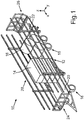
- a transport vehicle 10 is in a perspective view in FIG Fig. 1 shown.
- the loading platform 12 has a front loading platform part 20 mounted on a chassis 18 of the transport vehicle 10 and a rear loading platform part 22 which can be extended in the vehicle longitudinal direction x relative to the front loading platform part 20.
- a front end wall 24 At the front loading platform part 20 is a front end wall 24 and at the rear, extendable loading platform part 22 is a rear end wall 26 arranged for securing cargo.
- the loading platform 12 is also bounded laterally by two constructed in the form of lattice structures side walls 28.
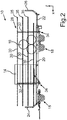
- Fig. 2 the transport vehicle 10 is shown in a side view.
- the lattice structure of one of the two side walls 28 is clearly visible.
- the side walls 28 are thus completely formed in the form of respective lattice structures, which have a plurality of horizontal struts 30 which are each hinged to two vertical struts 32.
- Respective lower longitudinal ends 34 of the vertical struts 32 are pivotably mounted on the front loading platform part 20 about respective unspecified pivot axes extending in the vehicle transverse direction y.
- the side walls 28 which are completely constructed in the form of the lattice structures can thereby be pivoted between an unfolded load securing position shown here, in which the vertical struts 32 extend in the vertical direction z of the transport vehicle 10, and a folded-off loading position in which the horizontal struts 30 abut one another.
- the side walls 28 formed in the form of the lattice structures also have a plurality of extension struts 35, which are arranged on the horizontal struts 30 for extending the side walls 28 in the vehicle longitudinal direction x.
- the length of the side walls 28 can thereby be adapted to the positioning of the extendable rear loading platform part 22.
- the extension struts 35 may be arranged longitudinally displaceably relative to the horizontal struts 30.
- Fig. 3 the transport vehicle 10 is shown in a further side view, wherein the two side walls 28 are shown in their folded-off loading position. A section A of the transport vehicle 10 is marked.
- Fig. 4 the detail A is shown in an enlarged detail view.
- the horizontal struts 32 in the vertical direction z abut each other when the side walls 28 have been brought into their folded-down loading position.
- respective hydraulic lifting cylinders 36 are provided on the transport vehicle 10 per side wall 28, by the actuation of which the side walls 28 are pivoted up and down can.
- the side walls 28 are preferably secured to the loading platform 12 and arranged such that the uppermost of the horizontal struts 30 in the folded-down loading position in the vehicle vertical direction z is either flush with a loading platform upper side or even below the loading platform upper side.
- the transport vehicle 10 can be loaded in a particularly simple manner from the side, if at least one of the side walls 28 is arranged in the folded-off loading position.
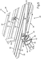
- a section of the transport vehicle 10 is shown in a perspective detail view, wherein one of the two side walls 28 is shown once in the folded-off loading position and with dashed lines in the unfolded load securing position.
- the transport vehicle 10 has an unspecified adjusting device, by means of which the side walls 28 designed as lattice structures are movable relative to the loading platform 12 in the vehicle transverse direction y.
- the adjusting device has a positive guide 38, by means of which the side walls 28 are moved away from the loading platform 12 when folded into the load securing position in the vehicle transverse direction y to the loading platform 12 and when folding down into the loading position.
- the forced guides 38 each have in the vehicle transverse direction y from an outside end portion 40 to an inside end portion 42 extending links 44, by means of which respective arranged on the longitudinal ends 34 of the vertical struts 32 guide elements 46 are positively driven in the unfolded load securing position on in each case inside end region 42 and in the folded-off loading position on the respective outer end region 40 of the links 44 are arranged.
- the guide elements 46 move in their respective scenes 44 in the vehicle transverse direction y to the outside, so that the side walls 28 in the vehicle transverse direction y move away from the loading platform 28.
- the guide elements 42 move forcibly in their respective scenes 44 in the vehicle transverse direction y inwards, so that the side walls 28 to move in the vehicle transverse direction y on the loading platform 28.
- the pivoting movement of the side walls 28 is coupled to a movement of the side walls 28 in the vehicle transverse direction y by the slide-like positive guides 38.
- a bottom side of the transport vehicle 10 is shown in a plan view, wherein the two side walls 28 are arranged in their folded down loading position. As can be seen, the two side walls 28 in the folded-down loading position in the vehicle transverse direction y are spaced from the loading platform 12.
- two of the positive guides 38 are also clearly visible, which are arranged in the region of the lower longitudinal ends 34. Each of the vertical struts 32 is thus guided by means of one of the positive guides 38, whereby the already explained motion coupling is achieved.
- a detailed view B of one of the forced guides 38 is also still in Fig. 6 shown.
- Fig. 7 the transport vehicle 10 is again shown in a plan view from below, wherein the side walls 28 are arranged in the present illustration in its upwardly pivoted load securing position.
- the two side walls 28 abut laterally on the loading platform 12 in their upwardly pivoted cargo securing position.
- the detail B is in Fig. 7 again shown in an enlarged view.
- the guide elements 46 which are positively guided within the respective slotted links 44, are located on the inside end region 42 when the side walls 28 have been pivoted upwards into the load securing position.
- the respective guide elements 46 in the respective scenes 44 migrate from the inside end region 42 to the outside end region 40, when the side walls 28 are pivoted from their folded up cargo securing position into the loading position folded downwards.
- the said adjustment of the transport vehicle 10 may alternatively or additionally, for example, a hydraulic adjustment mechanism, by means of which formed as a grid structures side walls 28 in the vehicle transverse direction y can be moved relative to the loading platform 12.
- a hydraulic adjustment mechanism by means of which formed as a grid structures side walls 28 in the vehicle transverse direction y can be moved relative to the loading platform 12.
- the hydraulic adjustment mechanism, the telescopic tubes in combination with the locking means and the positive guides 38 can also be combined with each other arbitrarily. Due to the adjustability of the side walls 28 in the vehicle transverse direction y relative to the loading platform 12, a load securing can be accomplished in a simple manner. Once the transport vehicle 10 has been loaded with the bale 14, 16 finished, the side walls 28 are folded upwards, whereby the bales 14, 16 are clamped between the two side walls 28.
- 16 can be carried out on the said hydraulic adjustment mechanism and / or the telescopic tubes, an additional adjustment of the side walls 28 in the vehicle transverse direction y, if necessary, the clamping of the bales 14, 16 between the side walls 28 in addition to increase.
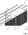
- Fig. 8 the transport vehicle 10 is shown in a perspective detail view, wherein at one of the two lattice-shaped side walls 28, a network structure 48 is attached.
- the network structure 48 may be, for example, a network or else a lattice-like structure of a plurality of belts.
- the net structure 48 is arranged in the vehicle transverse direction y between the horizontal struts 30 and the vertical struts 32 of the side wall 28 and preferably extends at least substantially along the entire side wall 28.
- the network structure 48 When unfolding the side wall 28 in the established load securing position, the network structure 48 is clamped, creating an additional Load securing function is provided by the network structure 48.
- the network structure 48 When folding down the side wall 28 in the lowered loading position, the network structure 48 is folded or folded so that it is not in the way of lateral loading of the transport vehicle 10 in the way.
- such network structures 48 can also be attached to both side walls 28, whereby a further improved load securing can be achieved. If, for example, individual parts of the bales 14, 16 come loose, they are prevented by the network structures 28 from falling from the transport vehicle. Furthermore, by attaching the net structures 28 on both sides, an even better clamping of the received bales 14, 16 in the vehicle transverse direction y can take place since the bales 14, 16 are clamped flatly between the network structures 48 attached to the side walls 28 when the side walls 28 are folded upwards Load securing position have been pivoted.
Description
Die Erfindung betrifft ein Transportfahrzeug für Stückgut, insbesondere für Ballen, der im Oberbegriff des Anspruchs 1 angegebenen Art.The invention relates to a transport vehicle for general cargo, in particular for bales, specified in the preamble of claim 1 Art.
In der Landwirtschaftsindustrie ist es an sich bekannt, als Ballenwagen bezeichnete Transportfahrzeuge zum Transportieren von Stückgut in Form von Heu- oder Strohballen zu verwenden. Die
Die Beladung des Transportfahrzeugs mit Stückgut, insbesondere mit Ballen, kann sich dabei relativ schwierig gestalten. Darüber hinaus kann auch eine Schwierigkeit darin bestehen, eine zuverlässige Ladungssicherung bei dem Transportfahrzeug vorzunehmen, sobald dieses mit Stückgut beladen worden ist.The loading of the transport vehicle with cargo, especially with bales, can make it relatively difficult. In addition, a difficulty may be to make a reliable load securing the transport vehicle once it has been loaded with cargo.
Die
Es ist daher die Aufgabe der vorliegenden Erfindung, ein Transportfahrzeug der eingangs genannten Art bereitzustellen, welches sich auf besonders bequeme Weise mit Stückgut beladen lässt und bei welchem auf besonders einfache Weise eine Ladungssicherung erzielt werden kann.It is therefore an object of the present invention to provide a transport vehicle of the type mentioned, which can be loaded in a particularly convenient way with cargo and in which a particularly simple way a load securing can be achieved.
Diese Aufgabe wird durch ein Transportfahrzeug für Stückgut, insbesondere für Ballen, mit den Merkmalen des Anspruchs 1 gelöst. Vorteilhafte Ausgestaltungen mit zweckmäßigen und nicht trivialen Weiterbildungen der Erfindung sind in den abhängigen Ansprüchen angegeben.This object is achieved by a transport vehicle for piece goods, in particular for bales, with the features of claim 1. Advantageous embodiments with expedient and non-trivial developments of the invention are specified in the dependent claims.
Das erfindungsgemäße Transportfahrzeug für Stückgut, insbesondere für Ballen, umfasst eine Ladeplattform, an welcher seitlich eine linke Seitenwand und eine rechte Seitenwand angeordnet sind. Das erfindungsgemäße Transportfahrzeug zeichnet sich dadurch aus, dass zumindest eine der Seitenwände vollständig in Form von einer Gitterstruktur ausgebildet ist, welche mehrere Horizontalstreben aufweist, die gelenkig an wenigstens zwei Vertikalstreben befestigt sind, deren untere Längsenden um jeweilige in Fahrzeugquerrichtung verlaufende Schwenkachsen verschwenkbar an der Ladeplattform gelagert sind, so dass die Gitterstruktur zwischen einer aufgeklappten Ladungssicherungsposition, in welcher die Vertikalstreben in Hochrichtung des Transportfahrzeugen verlaufen, und einer abgeklappten Beladungsposition, in welcher die Horizontalstreben aneinander anliegen, verschwenkbar ist.The transport vehicle according to the invention for piece goods, in particular for bales, comprises a loading platform on which a left side wall and a right side wall are arranged laterally. The transport vehicle according to the invention is characterized in that at least one of the side walls is formed completely in the form of a lattice structure having a plurality of horizontal struts which are hinged to at least two vertical struts, the lower longitudinal ends of which are pivotally mounted on the loading platform about respective pivot axes extending in the vehicle transverse direction are, so that the grid structure between an unfolded cargo securing position, in which the vertical struts extend in the vertical direction of the transport vehicles, and a folded-off loading position, in which the horizontal struts abut each other, is pivotable.
Bei dem erfindungsgemäßen Transportfahrzeug handelt es sich mit anderen Worten also um einen Ballenwagen, bei dem zumindest eine der Seitenwände in Form der besagten Gitterstruktur ausgebildet und zwischen der aufgeklappten Ladungssicherungsposition und der abgeklappten Beladungsposition hin und her verschwenkbar ist.In other words, the transport vehicle according to the invention is a bale carriage in which at least one of the side walls is designed in the form of said lattice structure and can be pivoted back and forth between the unfolded cargo securing position and the folded loading position.
Vorzugsweise sind beide Seitenwände des Transportfahrzeugs in Form der Gitterstruktur ausgebildet. Vorzugsweise ist also der gesamte seitliche Aufbau des Transportfahrzeugs zwischen der aufgeklappten Ladungssicherungsposition und der abgeklappten Beladungsposition hin und her verschwenkbar. Die Horizontalstreben sind dabei derart an den Vertikalstreben gelagert, dass die Horizontalstreben einen Drehfreiheitsgrad um jeweilige in Fahrzeugquerrichtung verlaufende Drehachsen aufweisen. Darüber hinaus umfasst das erfindungsgemäße Transportfahrzeug vorzugsweise eine Verriegelungsvorrichtung zum Arretieren der Gitterstruktur bzw. der Gitterstrukturen in einer jeweils gewünschten Position. Ferner kann das Transportfahrzeug auch eine Hubeinrichtung zum bequemen Auf- und Abklappen der Gitterstruktur bzw. der Gitterstrukturen aufweisen. Bei der Hubeinrichtung kann es sich um einen Hydraulikzylinder handeln, mittels welchem die Gitterstruktur auf und ab verschwenkbar ist.Preferably, both side walls of the transport vehicle are formed in the form of the lattice structure. Preferably, therefore, the entire lateral structure of the transport vehicle between the unfolded cargo securing position and the folded-off loading position is pivoted back and forth. The horizontal struts are mounted on the vertical struts such that the horizontal struts have a rotational degree of freedom about respective axes of rotation extending in the vehicle transverse direction. In addition, the transport vehicle according to the invention preferably comprises a locking device for locking the lattice structure or the lattice structures in a respective desired position. Furthermore, the transport vehicle can also have a lifting device for convenient folding and unfolding of the lattice structure or the lattice structures. The lifting device may be a hydraulic cylinder, by means of which the grid structure is pivotable up and down.
Dadurch, dass zumindest eine der Seitenwände vollständig in Form der besagten Gitterstruktur ausgebildet ist, kann das Transportfahrzeug besonders einfach beladen werden, indem die als Gitterstruktur ausgebildete Seitenwand einfach in die abgeklappte Beladungsposition verbracht wird. Danach kann das Transportfahrzeug auf besonders bequeme Weise von der Seite mit Stückgut, beispielsweise mit Heuballen oder dergleichen, beladen werden. Sobald die Beladung des Transportfahrzeugs abgeschlossen ist, kann die als Gitterstruktur ausgebildete Seitenwand von der abgeklappten Beladungsposition in die aufgeklappte Ladungssicherungsposition hochgeklappt werden. In der Ladungssicherungsposition kann auf zuverlässige Weise sichergestellt werden, dass das aufgeladene Stückgut nicht seitlich von dem Transportfahrzeug herunterfällt.Characterized in that at least one of the side walls is formed completely in the form of said lattice structure, the transport vehicle can be particularly easily loaded by the formed as a grid structure side wall is simply moved into the folded-off loading position. Thereafter, the transport vehicle can be loaded in a particularly convenient way from the side with cargo, such as hay bales or the like. As soon as the loading of the transport vehicle has been completed, the side wall designed as a grid structure can be folded from the folded-down loading position into the unfolded load securing position. In the load securing position can be reliably ensured that the loaded cargo does not fall laterally from the transport vehicle.
Um eine besonders einfache Beladung des Transportfahrzeugs ermöglichen zu können, ist es vorzugsweise vorgesehen, dass die oberste der Horizontalstreben in der abgeklappten Beladungsposition in Fahrzeughochrichtung bündig mit einer Ladeplattformoberseite abschließt oder unterhalb von der Ladeplattformoberseite angeordnet ist. In der abgeklappten Beladungsposition ist also keine der Horizontalstreben in Fahrzeugquerrichtung im Weg, so dass das Transportfahrzeug auf ganz einfache Weise von der Seite mit Stückgut beladen werden kann. Vorzugsweise sind die Horizontalstreben dabei derart an den Vertikalstreben befestigt, dass in der abgeklappten Beladungsposition auch die Vertikalstreben entweder bündig mit der Ladeplattformoberseite abschließen oder sogar unterhalb von der Ladeplattformoberseite angeordnet sind. Die Ladeplattform des Transportfahrzeugs kann dadurch auf ganz einfache Weise von der Seite her beladen werden, da keine störenden Strukturen im Weg sind.In order to enable a particularly simple loading of the transport vehicle, it is preferably provided that the uppermost of the horizontal struts in the folded-off loading position in the vehicle vertical direction is flush with a loading platform top or below the loading platform top. In the folded loading position so none of the horizontal struts in the vehicle transverse direction in the way, so that the transport vehicle can be loaded in a very simple way from the side with cargo. Preferably, the horizontal struts are attached to the vertical struts so that in the folded-off loading position, the vertical struts either flush with the loading platform top complete or even below the loading platform top are arranged. The loading platform of the transport vehicle can be loaded in a very simple way from the side, since no disturbing structures are in the way.
Eine weitere vorteilhafte Ausführungsform der Erfindung sieht vor, dass das Transportfahrzeug eine Verstelleinrichtung aufweist, mittels welcher die Gitterstruktur in Fahrzeugquerrichtung relativ zur Ladeplattform bewegbar ist. Die zumindest eine als Gitterstruktur ausgebildete Seitenwand kann also auf die Ladeplattform zu und von dieser weg bewegt werden. Dadurch ist es auf einfache Weise möglich, auf der Ladeplattform angeordnetes Stückgut, beispielsweise Heuballen oder dergleichen, zwischen den beiden Seitenwänden einzuklemmen, wodurch eine besonders zuverlässige Ladungssicherung erzielt werden kann.A further advantageous embodiment of the invention provides that the transport vehicle has an adjusting device, by means of which the grid structure in the vehicle transverse direction is movable relative to the loading platform. The at least one side wall designed as a grid structure can thus be moved to and from the loading platform. This makes it possible in a simple manner, clamped on the loading platform piece goods, such as hay bales or the like, clamped between the two side walls, whereby a particularly reliable load securing can be achieved.
Gemäß einer weiteren vorteilhaften Ausführungsform der Erfindung ist es vorgesehen, dass die Verstelleinrichtung eine Zwangsführung aufweist, mittels welcher die Gitterstruktur beim Aufklappen in die Ladungssicherungsposition in Fahrzeugquerrichtung auf die Ladeplattform zu und beim Abklappen in die Beladungsposition von der Ladeplattform weg bewegt wird. Die Verschwenkbewegung der Gitterstruktur ist mit anderen Worten also vorzugsweise zwangsgekoppelt an eine Verschiebung der Gitterstruktur in Fahrzeugquerrichtung, und zwar derart, dass die Gitterstruktur in der abgeklappten Beladungsposition in Fahrzeugquerrichtung weiter von der Ladeplattform entfernt angeordnet ist als in der aufgeklappten Ladungssicherungsposition. Wird also die Gitterstruktur nach dem Beladen des Transportfahrzeugs von der abgeklappten Beladungsposition in die aufgeklappte Ladungssicherungsposition verbracht, so kann auf der Ladeplattform angeordnetes Stückgut automatisch in Fahrzeugquerrichtung zwischen den beiden Seitenwänden eingeklemmt werden, um eine zuverlässige Ladungssicherung zu erzielen.According to a further advantageous embodiment of the invention, it is provided that the adjusting device comprises a positive guide, by means of which the grid structure is moved away from the loading platform on opening in the load securing position in the vehicle transverse direction to the loading platform and when folding into the loading position. In other words, the pivoting movement of the lattice structure is preferably positively coupled to a displacement of the lattice structure in the vehicle transverse direction, in such a way that the lattice structure is further away from the loading platform in the folded load position in the vehicle transverse direction than in the unfolded cargo securing position. Thus, if the grid structure is spent after loading the transport vehicle from the folded loading position in the unfolded cargo securing position, so arranged on the loading platform cargo can be automatically clamped in the vehicle transverse direction between the two side walls to achieve a reliable load securing.
Eine weitere vorteilhafte Ausführungsform der Erfindung sieht vor, dass die Zwangsführung jeweilige sich in Fahrzeugquerrichtung von einem außenseitigen Endbereich zu einem innenseitigen Endbereich erstreckende Kulissen aufweist, mittels welchen jeweilige an den Längsenden der Vertikalstreben angeordnete Führungselemente zwangsgeführt sind, die in der aufgeklappten Ladungssicherungsposition am jeweils innenseitigen Endbereich und in der abgeklappten Beladungsposition am jeweils außenseitigen Endbereich der Kulissen angeordnet sind. Mit anderen Worten weist das Transportfahrzeug also für die zumindest eine Gitterstruktur eine Kulissenführung auf, mittels welcher die Bewegungskopplung der Gitterstruktur hinsichtlich der Bewegung in Fahrzeugquerrichtung und dem Auf- bzw. Abschwenken bewerkstelligt wird. Dadurch kann auf besonders einfache und zuverlässige Weise die Bewegung der Gitterstruktur in Fahrzeugquerrichtung zur Ladungssicherung erzielt werden. Insbesondere muss ein Benutzer des Transportfahrzeugs nicht aktiv noch die zumindest eine als Gitterstruktur ausgebildete Seitenwand in Fahrzeugquerrichtung verschieben, denn dies geschieht automatisch beim Auf- und Abklappen der als Gitterstruktur ausgebildeten Seitenwand.A further advantageous embodiment of the invention provides that the positive guide has respective scenes extending in the vehicle transverse direction from an outside end area to an inside end area, by means of which respective guide elements arranged at the longitudinal ends of the vertical struts are forcibly guided, those in the unfolded load securing position on the respective inside end area and in the folded-off loading position on the respective outside End region of the scenes are arranged. In other words, the transport vehicle for the at least one grid structure on a sliding guide, by means of which the movement coupling of the grid structure with respect to the movement in the vehicle transverse direction and the up or pivoting is accomplished. As a result, the movement of the grid structure in the vehicle transverse direction for load securing can be achieved in a particularly simple and reliable manner. In particular, a user of the transport vehicle does not have to actively move the at least one side wall designed as a grid structure in the vehicle transverse direction, because this happens automatically when folding up and down the sidewall formed as a grid structure.
In weiterer vorteilhafter Ausgestaltung der Erfindung ist es vorgesehen, dass die Verstelleinrichtung einen hydraulischen Verstellmechanismus aufweist, mittels welchem die Gitterstruktur in Fahrzeugquerrichtung relativ zur Ladeplattform bewegbar ist. Unter Verwendung des hydraulischen Verstellmechanismus kann ein Benutzer die auf dem Transportfahrzeug aufgenommene Ladung auf besonders einfache Weise manuell sichern, indem er durch Betätigung des hydraulischen Verstellmechanismus bewirkt, dass die auf dem Transportfahrzeug aufgenommene Ladung zwischen den beiden Seitenwänden eingeklemmt wird. Der hydraulische Verstellmechanismus kann dabei auch in Kombination mit der kulissengeführten Zwangsverschiebung in Fahrzeugquerrichtung der Gitterstruktur erfolgen. Einerseits wird die Gitterstruktur also in bereits erläuterter Weise beim Aufschwenken in die Ladungssicherungsposition auf die Ladeplattform zu bewegt, wodurch schon eine gewisse Einquetschung des aufgenommenen Stückguts in Fahrzeugquerrichtung erfolgen kann. Sollte dies gegebenenfalls nicht ausreichend sein, so kann auch zusätzlich der hydraulische Verstellmechanismus betätigt werden, um die zumindest eine als Gitterstruktur ausgebildete Seitenwand noch stärker auf die Ladeplattform zu in Fahrzeugquerrichtung zu verschieben.In a further advantageous embodiment of the invention, it is provided that the adjusting device has a hydraulic adjusting mechanism, by means of which the grid structure in the vehicle transverse direction is movable relative to the loading platform. Using the hydraulic adjustment mechanism, a user can manually secure the charge received on the transport vehicle in a particularly simple manner by causing actuation of the hydraulic adjustment mechanism that the charge received on the transport vehicle between the two side walls is clamped. The hydraulic adjustment mechanism can also be done in combination with the backdrop-driven positive displacement in the vehicle transverse direction of the grid structure. On the one hand, the grid structure is thus moved in the already explained manner when swiveling in the load securing position on the loading platform, which can already be done a certain pinching of the recorded piece goods in the vehicle transverse direction. If this may not be sufficient, the hydraulic adjusting mechanism can also be actuated in order to move the at least one side wall formed as a grid structure even more strongly towards the loading platform in the vehicle transverse direction.
Eine weitere vorteilhafte Ausführungsform der Erfindung sieht vor, dass die Verstelleinrichtung wenigstens ein Teleskoprohr aufweist, mittels welchem die Gitterstruktur in Fahrzeugquerrichtung relativ zur Ladeplattform bewegbar ist, wobei die Verstelleinrichtung zumindest ein Arretiermittel, insbesondere einen Steckbolzen, zum Arretieren des Teleskoprohrs umfasst. Auch mittels des Teleskoprohrs kann auf einfache Weise eine Ladungssicherung erzielt werden, da mit Hilfe des Teleskoprohrs und des Arretiermittels die zumindest eine als Gitterstruktur ausgebildete Seitenwand in Fahrzeugquerrichtung relativ zur Ladeplattform bewegt werden kann. Die Lösung mit dem Teleskoprohr und dem Arretiermittel kann dabei sowohl mit dem hydraulischen Verstellmechanismus als auch mit dem kulissengeführten Verstellmechanismus kombiniert werden, wobei auch alle drei Lösungen miteinander kombiniert werden können. Beispielsweise kann das Teleskoprohr gemeinsam mit dem Arretiermittel dazu verwendet werden, eine bestimmte Lage der Gitterstruktur in Fahrzeugquerrichtung festzulegen. In Kombination mit dem hydraulischen Verstellmechanismus und der Kulissenführung kann dann zusätzlich noch eine stärkere Verstellung der Gitterstruktur in Fahrzeugquerrichtung zur Ladungssicherung erfolgen.A further advantageous embodiment of the invention provides that the adjusting device has at least one telescopic tube, by means of which the grid structure in the vehicle transverse direction relative to the loading platform is movable, wherein the adjusting device comprises at least one locking means, in particular a locking pin for locking the telescopic tube. Also, by means of the telescopic tube, a load securing can be achieved in a simple manner, since with the help of the telescopic tube and the locking means, the at least one formed as a grid structure side wall in the vehicle transverse direction can be moved relative to the loading platform. The solution with the telescopic tube and the locking means can be combined with both the hydraulic adjustment mechanism as well as with the setting-guided adjustment mechanism, whereby all three solutions can be combined. For example, the telescopic tube can be used together with the locking means to set a specific position of the grid structure in the vehicle transverse direction. In combination with the hydraulic adjusting mechanism and the slotted guide, a stronger adjustment of the grid structure in the vehicle transverse direction for securing the load can additionally take place.
Gemäß einer weiteren vorteilhaften Ausführungsform der Erfindung ist es vorgesehen, dass die Ladeplattform einen auf einem Fahrgestell des Transportfahrzeugs befestigten vorderen Ladeplattformteil, an welchem die unteren Längsenden der Vertikalstreben gelagert sind, und einen in Fahrzeuglängsrichtung relativ zum ersten Ladeplattformteil ausziehbaren hinteren Ladeplattformteil umfasst. Vorzugsweise ist dabei am vorderen Ladeplattformteil eine vordere Stirnwand und am hinteren Ladeplattformteil eine hintere Stirnwand angeordnet. Der hintere Ladeplattformteil bildet eine Art ausziehbare Brücke, mittels welcher bei Bedarf die Länge der Ladefläche des Transportfahrzeugs vergrößert und verkleinert werden kann. Darüber hinaus bringt der ausziehbare hintere Ladeplattformteil noch den Vorteil mit sich, dass bei einer Fahrt mit dem Transportfahrzeug auf öffentlichen Verkehrswegen durch Einfahren des hinteren Ladeplattformteils sichergestellt werden kann, dass eine gesetzlich vorgegebene Gesamtlänge des Transportfahrzeugs, gegebenenfalls in Kombination mit einem Zugfahrzeug, nicht überschritten wird.According to a further advantageous embodiment of the invention, it is provided that the loading platform comprises a mounted on a chassis of the transport vehicle front loading platform part on which the lower longitudinal ends of the vertical struts are mounted, and extending in the vehicle longitudinal direction relative to the first loading platform part rear loading platform part. Preferably, a front end wall is arranged on the front loading platform part and a rear end wall on the rear loading platform part. The rear loading platform part forms a kind of extendable bridge, by means of which, if necessary, the length of the loading area of the transport vehicle can be increased and decreased. In addition, the extendable rear loading platform part still brings with it the advantage that when driving with the transport vehicle on public roads by retracting the rear loading platform part can be ensured that a statutory total length of the transport vehicle, possibly in combination with a towing vehicle is not exceeded ,
Eine weitere vorteilhafte Ausführungsform der Erfindung sieht vor, dass die Gitterstruktur mehrere Verlängerungsstreben aufweist, welche zur Verlängerung der Gitterstruktur in Fahrzeuglängsrichtung an den Horizontalstreben anordnenbar sind. Insbesondere in Kombination mit dem ausziehbaren hinteren Ladeplattformteil ist dies von Vorteil, da durch Anbringen bzw. entsprechendes Einstellen der Verlängerungsstreben die Länge der Gitterstruktur in Fahrzeuglängsrichtung entsprechend zur Positionierung des hinteren Ladeplattformteils angepasst werden kann. Wird also der hintere Ladeplattformteil besonders weit ausgezogen, so können entsprechende Verlängerungsstreben angebracht bzw. derart positioniert werden, dass eine Ladungssicherung entlang der gesamten Ladeplattform sichergestellt werden kann.A further advantageous embodiment of the invention provides that the grid structure has a plurality of extension struts, which can be arranged to extend the grid structure in the vehicle longitudinal direction of the horizontal struts. This is advantageous in particular in combination with the extendable rear loading platform part, since the length of the lattice structure in the vehicle longitudinal direction can be adjusted in accordance with the positioning of the rear loading platform part by attaching or correspondingly adjusting the extension struts. Thus, if the rear loading platform part is pulled out particularly far, appropriate extension struts can be attached or positioned in such a way that load securing can be ensured along the entire loading platform.
Schließlich ist es gemäß einer weiteren vorteilhaften Ausführungsform der Erfindung vorgesehen, dass die Verlängerungsstreben relativ zu den Horizontalstreben längsverschiebbar an diesen anordnenbar sind. Beispielsweise können die Verlängerungsstreben teleskopartig ausgebildet sein, so dass diese je nach Bedarf aus den Horizontalstreben herausgezogen und wiederum in diese hineinbewegt werden können. Ferner können beispielsweise noch Arretiermittel in Form von Bolzen oder dergleichen vorgesehen sein, mittels welchen die Positionierung der Verlängerungsstreben relativ zu den Horizontalstreben festlegbar ist. Dadurch kann auf besonders einfache Weise sichergestellt werden, dass eine Ladungssicherung entlang der gesamten Länge der Ladeplattform jederzeit sichergestellt werden kann, indem die Verlängerungsstreben gerade entsprechend der Länge der Ladeplattform positioniert werden können.Finally, it is provided according to a further advantageous embodiment of the invention that the extension struts are arranged longitudinally displaceable relative to the horizontal struts on this. For example, the extension struts may be telescopic, so that they can be pulled out as needed from the horizontal struts and in turn moved into this. Furthermore, for example, locking means in the form of bolts or the like can still be provided, by means of which the positioning of the extension struts can be fixed relative to the horizontal struts. This can be ensured in a particularly simple manner that a load securing along the entire length of the loading platform can be ensured at any time by the extension struts can be positioned just according to the length of the loading platform.
Weitere Vorteile, Merkmale und Einzelheiten der Erfindung ergeben sich aus der nachfolgenden Beschreibung eines bevorzugten Ausführungsbeispiels sowie anhand der Zeichnung. Die vorstehend in der Beschreibung genannten Merkmale und Merkmalskombinationen sowie die nachfolgend in der Figurenbeschreibung genannten Merkmale und Merkmalskombinationen sind dabei nicht nur in der angegebenen Kombination, sondern auch in Alleinstellung oder in anderen Kombinationen verwendbar, ohne den Rahmen der Erfindung zu verlassen.Further advantages, features and details of the invention will become apparent from the following description of a preferred embodiment and from the drawing. The features and feature combinations mentioned above in the description as well as the features and feature combinations mentioned below in the description of the figures can be used not only in the specified combination but also alone or in other combinations, without departing from the scope of the invention.
Die Zeichnung zeigt in:
- Fig. 1
- eine Perspektivansicht eines Transportfahrzeugs, auf dessen Ladeplatt-form mehrere zylinderförmige und quaderförmige Heuballen angeordnet sind, wobei die Ladeplattform seitlich von zwei gitterförmig ausgebildeten Seitenwänden und in Fahrzeuglängsrichtung von zwei gitterförmigen Stirnwänden begrenzt wird;
- Fig. 2
- eine Seitenansicht des mit den Heuballen beladenen Transportfahrzeugs;
- Fig. 3
- eine weitere Seitenansicht des Transportfahrzeugs, wobei die beiden Seitenwände in einer abgeklappten Position dargestellt sind;
- Fig. 4
- eine Detailansicht von einer der beiden abgeklappten Seitenwände;
- Fig. 5
- eine perspektivische Detailansicht des Transportfahrzeugs, wobei eine der beiden Seitenwände sowohl einmal in der abgeklappten als auch in der aufgestellten Position dargestellt ist;
- Fig. 6
- eine Draufsicht auf die Unterseite des Transportfahrzeugs, wobei die Seitenwände in ihrer abgeklappten Position dargestellt sind, in welcher diese in Fahrzeugquerrichtung von der Ladeplattform beabstandet sind, wobei in einer Detailansicht eine Kulisse dargestellt ist, welche zur seitlichen Verschiebung von einer der Seitenwände dient;
- Fig. 7
- eine weitere Draufsicht auf die Unterseite des Transportfahrzeugs, wobei die Seitenwände in der aufgeklappten Position angeordnet sind, in welcher die Seitenwände in Fahrzeugquerrichtung an der Ladeplattform anliegen, wobei erneut eine der Kulissen, welche zur seitlichen Verschiebung von einer der Seitenwände dient, in einer Detailansicht gezeigt ist; und in
- Fig. 8
- eine perspektivische Detailansicht des Transportfahrzeugs, wobei an einer der beiden gitterförmig ausgebildeten Seitenwände eine Netzstruktur angebracht ist.
- Fig. 1
- a perspective view of a transport vehicle, on the Ladeplatt-form a plurality of cylindrical and cuboid hay bales are arranged, wherein the loading platform is bounded laterally by two lattice-shaped side walls and in the vehicle longitudinal direction of two lattice-shaped end walls;
- Fig. 2
- a side view of the laden with hay bales transport vehicle;
- Fig. 3
- a further side view of the transport vehicle, wherein the two side walls are shown in a folded position;
- Fig. 4
- a detailed view of one of the two folded side walls;
- Fig. 5
- a detailed perspective view of the transport vehicle, wherein one of the two side walls is shown both once in the folded and in the deployed position;
- Fig. 6
- a top view of the underside of the transport vehicle, wherein the side walls are shown in their folded position in which they are spaced in the vehicle transverse direction of the loading platform, wherein in a detailed view of a gate is shown, which serves for the lateral displacement of one of the side walls;
- Fig. 7
- a further plan view of the underside of the transport vehicle, wherein the side walls are arranged in the unfolded position in which the side walls in the vehicle transverse direction abut against the loading platform, wherein again one of the scenes, which serves for the lateral displacement of one of the side walls shown in a detailed view is; and in
- Fig. 8
- a detailed perspective view of the transport vehicle, wherein at one of the two lattice-shaped side walls, a network structure is attached.
In den Figuren werden gleiche oder funktionsgleiche Elemente mit gleichen Bezugszeichen versehen.In the figures, identical or functionally identical elements are provided with the same reference numerals.
Ein Transportfahrzeug 10 ist in einer Perspektivansicht in
In
Die in Form der Gitterstrukturen ausgebildeten Seitenwände 28 weisen zudem mehrere Verlängerungsstreben 35 auf, welche zur Verlängerung der Seitenwände 28 in Fahrzeuglängsrichtung x an den Horizontalstreben 30 angeordnet sind. Die Länge der Seitenwände 28 kann dadurch an die Positionierung des ausziehbaren hinteren Ladeplattformteils 22 angepasst werden. Beispielsweise können die Verlängerungsstreben 35 relativ zu den Horizontalstreben 30 längsverschiebbar an diesen angeordnet sein.The
In
In
In
Im vorliegend gezeigten Ausführungsbeispiel weisen die Zwangsführungen 38 jeweilige sich in Fahrzeugquerrichtung y von einem außenseitigen Endbereich 40 zu einem innenseitigen Endbereich 42 erstreckende Kulissen 44 auf, mittels welchen jeweilige an den Längsenden 34 der Vertikalstreben 32 angeordnete Führungselemente 46 zwangsgeführt sind, die in der aufgeklappten Ladungssicherungsposition am jeweils innenseitigen Endbereich 42 und in der abgeklappten Beladungsposition am jeweils außenseitigen Endbereich 40 der Kulissen 44 angeordnet sind.In the presently illustrated embodiment, the forced guides 38 each have in the vehicle transverse direction y from an
Werden also die Seitenwände 28 nach unten in die Beladungsposition abgeklappt, so wandern die Führungselemente 46 in ihren jeweiligen Kulissen 44 in Fahrzeugquerrichtung y nach außen, so dass sich die Seitenwände 28 in Fahrzeugquerrichtung y von der Ladeplattform 28 wegbewegen. Werden die Seitenwände 28 hingegen von ihrer heruntergeklappten Beladungsposition in ihre aufgestellte Ladungssicherungsposition hochgeklappt, so wandern die Führungselemente 42 in ihren jeweiligen Kulissen 44 zwangsgeführt in Fahrzeugquerrichtung y nach innen, so dass sich die Seitenwände 28 in Fahrzeugquerrichtung y auf die Ladeplattform 28 zu bewegen. Mit anderen Worten ist also durch die kulissenartigen Zwangsführungen 38 die Verschwenkbewegung der Seitenwände 28 an eine Bewegung der Seitenwände 28 in Fahrzeugquerrichtung y gekoppelt.Thus, if the
In
In
Neben der Zwangskopplung der Klapp- und Seitwärtsbewegung der Seitenwände 28 kann die besagte Verstelleinrichtung des Transportfahrzeugs 10 alternativ oder zusätzlich auch beispielsweise einen hydraulischen Verstellmechanismus aufweisen, mittels welchem die als Gitterstrukturen ausgebildeten Seitenwände 28 in Fahrzeugquerrichtung y relativ zur Ladeplattform 12 bewegt werden können. Des Weiteren ist es auch möglich, dass die besagte Verstelleinrichtung des Transportfahrzeugs 10 je Seitenwand 28 ein in Fahrzeugquerrichtung y verlaufendes Teleskoprohr aufweist, mittels welchem die jeweiligen Seitenwände 28 in Fahrzeugquerrichtung y relativ zur Ladeplattform 12 bewegbar sind, wobei jeweilige Arretiermittel, beispielsweise in Form von Steckbolzen, vorgesehen sein können, mittels welchen die ausgezogenen Teleskoprohre arretiert werden können.In addition to the positive coupling of the folding and sideways movement of the
Der hydraulische Verstellmechanismus, die Teleskoprohre in Kombination mit den Arretiermitteln und die Zwangsführungen 38 können dabei auch beliebig miteinander kombiniert werden. Durch die Verstellbarkeit der Seitenwände 28 in Fahrzeugquerrichtung y relativ zur Ladeplattform 12 kann auf einfache Weise eine Ladungssicherung bewerkstelligt werden. Sobald das Transportfahrzeug 10 mit den Ballen 14, 16 fertig beladen worden ist, werden die Seitenwände 28 nach oben geklappt, wodurch die Ballen 14, 16 zwischen den beiden Seitenwänden 28 eingeklemmt werden. Je nach Abmaßen des Transportfahrzeugs 10 und je nach Abmaßen der aufzuladenden Ballen 14, 16 kann über den besagten hydraulischen Verstellmechanismus und/oder die Teleskoprohre eine zusätzliche Verstellung der Seitenwände 28 in Fahrzeugquerrichtung y erfolgen, um gegebenenfalls die Klemmung der Ballen 14, 16 zwischen den Seitenwänden 28 noch zusätzlich zu erhöhen.The hydraulic adjustment mechanism, the telescopic tubes in combination with the locking means and the
In
Entgegen der hier gezeigten Ausführungsform des Transportfahrzeugs 10 können auch an beiden Seitenwänden 28 derartige Netzstrukturen 48 angebracht sein, wodurch eine nochmals verbesserte Ladungssicherung erzielt werden kann. Sollten sich beispielsweise einzelne Teile von den Ballen 14, 16 lösen, werden diese durch die Netzstrukturen 28 am Herunterfallen vom Transportfahrzeug gehindert. Ferner kann durch eine beidseitige Anbringung der Netzstrukturen 28 eine noch bessere Klemmung der aufgenommenen Ballen 14, 16 in Fahrzeugquerrichtung y erfolgen, da die Ballen 14, 16 flächig zwischen den an den Seitenwänden 28 angebrachten Netzstrukturen 48 eingeklemmt werden, wenn die Seitenwände 28 in die hochgeklappte Ladungssicherungsposition verschwenkt worden sind.Contrary to the embodiment of the
- 1010
- Transportfahrzeugtransport vehicle
- 1212
- Ladeplattformloading platform
- 1414
- Ballenbale
- 1616
- Ballenbale
- 1818
- Fahrgestellchassis
- 2020
- vorderer Ladeplattformteilfront loading platform part
- 2222
- hinterer Ladeplattformteilrear loading platform part
- 2424
- vordere Stirnwandfront end wall
- 2626
- hintere Stirnwandrear end wall
- 2828
- SeitenwandSide wall
- 3030
- HorizontalstrebeHorizontal strut
- 3232
- Vertikalstrebevertical strut
- 3434
- unteres Längsendelower longitudinal end
- 3535
- Verlängerungsstrebeextension strut
- 3636
- Hubzylinderlifting cylinder
- 3838
- Zwangsführungforced control
- 4040
- außenseitiger Endbereichoutside end area
- 4242
- innenseitiger Endbereichinside end area
- 4444
- Kulissescenery
- 4646
- Führungselementguide element
- 4848
- Netzstrukturnetwork structure
- AA
- Detailansichtdetailed view
- BB
- Detailansichtdetailed view
- xx
- FahrzeuglängsrichtungVehicle longitudinal direction
- yy
- FahrzeugquerrichtungVehicle transverse direction
- zz
- FahrzeughochrichtungVehicle vertical direction
Claims (10)
- Transport vehicle (10) for general cargo, in particular for bales (14, 16), including a loading platform (12), at which a left sidewall (28) and a right sidewall (28) are laterally arranged,
characterized in that
at least one of the sidewalls (28) is completely formed in the form of a grid structure, which comprises multiple horizontal struts (30), which are attached to at least two vertical struts (32) in articulated manner, the lower longitudinal ends (34) of which are supported on the loading platform (12) pivotable around respective pivot axes extending in vehicle transverse direction (y), such that the grid structure is pivotable between a folded-up load securing position, in which the vertical struts (32) extend in vertical direction (z) of the transport vehicle (10), and a folded-down loading position, in which the horizontal struts (30) abut on each other. - Transport vehicle (10) according to claim 1,
characterized in that
in the folded-down loading position, the uppermost of the horizontal struts (30) is flush with a loading platform topside or is arranged below the loading platform topside in vehicle vertical direction (z). - Transport vehicle (10) according to claim 1 or 2,
characterized in that
the transport vehicle (10) comprises an adjusting device, by means of which the grid structure is movable relative to the loading platform (12) in vehicle transverse direction (y). - Transport vehicle (10) according to claim 3,
characterized in that
the adjusting device comprises a compulsory guide (38), by means of which the grid structure is moved towards the loading platform (12) upon folding up into the load securing position in vehicle transverse direction (y) and away from the loading platform (12) upon folding down into the loading position. - Transport vehicle (10) according to claim 4,
characterized in that
the compulsory guide (38) comprises respective links (44) extending from an exterior end area (40) to an interior end area (42) in vehicle transverse direction (y), by means of which respective guiding elements (46) arranged at the longitudinal ends (34) of the vertical struts (32) are compulsorily guided, which are arranged at the respectively interior end area (42) in the folded-up load securing position and at the respectively exterior end area (40) of the links (44) in the folded-down loading position. - Transport vehicle (10) according to any one of claims 3 to 5,
characterized in that
the adjusting device comprises a hydraulic adjusting mechanism, by means of which the grid structure is movable relative to the loading platform (12) in vehicle transverse direction (y). - Transport vehicle (10) according to any one of claims 3 to 6,
characterized in that
the adjusting device comprises at least one telescopic tube, by means of which the grid structure is movable relative to the loading platform (12) in vehicle transverse direction (y), wherein the adjusting device includes at least one locking means, in particular a plug bolt, for locking the telescopic tube. - Transport vehicle (10) according to any one of the preceding claims,
characterized in that
the loading platform (12) includes a front loading platform part (20) attached on a chassis (18) of the transport vehicle (10), on which the lower longitudinal ends (34) of the vertical struts (32) are supported, and a rear loading platform part (22) extensible relative to the front loading platform part (20) in vehicle longitudinal direction (x). - Transport vehicle (10) according to any one of the preceding claims,
characterized in that
the grid structure comprises multiple extension struts (35), which can be arranged at the horizontal struts (30) for extending the grid structure in vehicle longitudinal direction (x). - Transport vehicle (10) according to claim 9,
characterized in that
the extension struts (35) can be arranged at the horizontal struts (30) longitudinally displaceable relative to them.
Priority Applications (1)
| Application Number | Priority Date | Filing Date | Title |
|---|---|---|---|
| PL16199147T PL3173286T3 (en) | 2015-11-18 | 2016-11-16 | Transport vehicle for piece goods |
Applications Claiming Priority (1)
| Application Number | Priority Date | Filing Date | Title |
|---|---|---|---|
| DE202015106266.4U DE202015106266U1 (en) | 2015-11-18 | 2015-11-18 | Transport vehicle for general cargo |
Publications (2)
| Publication Number | Publication Date |
|---|---|
| EP3173286A1 EP3173286A1 (en) | 2017-05-31 |
| EP3173286B1 true EP3173286B1 (en) | 2018-09-26 |
Family
ID=55274349
Family Applications (1)
| Application Number | Title | Priority Date | Filing Date |
|---|---|---|---|
| EP16199147.6A Active EP3173286B1 (en) | 2015-11-18 | 2016-11-16 | Transport vehicle for piece goods |
Country Status (5)
| Country | Link |
|---|---|
| EP (1) | EP3173286B1 (en) |
| DE (1) | DE202015106266U1 (en) |
| HU (1) | HUE042441T2 (en) |
| PL (1) | PL3173286T3 (en) |
| RU (1) | RU2708873C2 (en) |
Cited By (2)
| Publication number | Priority date | Publication date | Assignee | Title |
|---|---|---|---|---|
| EP4305952A1 (en) * | 2022-07-14 | 2024-01-17 | Pöttinger Landtechnik GmbH | Agricultural loader |
| FR3139519A1 (en) | 2022-09-13 | 2024-03-15 | Sarl Ponge Pere Et Fils | DEVICE FOR SECURING LOADS, IN PARTICULAR BALES OF FORAGE, ON A LOAD TRANSPORT VEHICLE, AND LOAD TRANSPORT VEHICLE COMPRISING AT LEAST ONE SUCH LOCKING DEVICE |
Families Citing this family (1)
| Publication number | Priority date | Publication date | Assignee | Title |
|---|---|---|---|---|
| FR3081284B1 (en) * | 2018-05-28 | 2020-08-14 | Soc Ind D'applications Mecaniques | FORAGE PLATE |
Family Cites Families (10)
| Publication number | Priority date | Publication date | Assignee | Title |
|---|---|---|---|---|
| AT266617B (en) * | 1966-11-23 | 1968-11-25 | Niederoesterr Molkerei | Foldable side wall for trucks, especially trucks or the like. |
| SU417335A1 (en) * | 1971-02-16 | 1974-02-28 | ||
| DE2538079C2 (en) * | 1975-08-27 | 1983-02-24 | Maschinenfabrik Fahr Ag Gottmadingen, 7702 Gottmadingen | Agricultural vehicle such as loading, harvesting, chopping wagons or the like |
| DE2901597C2 (en) * | 1979-01-17 | 1985-05-15 | Maschinenfabriken Bernard Krone Gmbh, 4441 Spelle | Agricultural harvesting wagon with a two-part wagon body that forms the loading space |
| SU1214509A1 (en) * | 1983-05-04 | 1986-02-28 | Lukyanchuk Dmitrij V | Vehicle for transporting bulk agricultural freight |
| DE4005429A1 (en) | 1989-04-21 | 1990-10-25 | Poettinger Alois Landmasch | Agricultural harvesting self loader - has number of hydraulic devices controlled by servo motor and series of valves |
| DE4223951A1 (en) * | 1992-07-21 | 1994-01-27 | Peter Dr Ing Boese | Support device for interchangeable containers and vehicle platforms - has automatically extending supports and mechanically operated locks to move and connect containers without manual intervention. |
| RU2067059C1 (en) * | 1996-04-08 | 1996-09-27 | Юрий Петрович Милай | Vehicle convertible body |
| RU2314672C2 (en) * | 2006-03-02 | 2008-01-20 | Федеральное государственное образовательное учреждение высшего профессионального образования "Ярославская государственная сельскохозяйственная академия" | Vehicle for loading, transportation and unloading of cylindrical hay and forage bales |
| RU125939U1 (en) * | 2012-10-01 | 2013-03-20 | Открытое акционерное общество "Нефтекамский автозавод" | SEMITRAILER FOR TRANSPORT OF GRAIN CROPS AND OTHER BULK CARGOES |
-
2015
- 2015-11-18 DE DE202015106266.4U patent/DE202015106266U1/en active Active
-
2016
- 2016-11-16 EP EP16199147.6A patent/EP3173286B1/en active Active
- 2016-11-16 PL PL16199147T patent/PL3173286T3/en unknown
- 2016-11-16 HU HUE16199147A patent/HUE042441T2/en unknown
- 2016-11-17 RU RU2016145073A patent/RU2708873C2/en active
Non-Patent Citations (1)
| Title |
|---|
| None * |
Cited By (3)
| Publication number | Priority date | Publication date | Assignee | Title |
|---|---|---|---|---|
| EP4305952A1 (en) * | 2022-07-14 | 2024-01-17 | Pöttinger Landtechnik GmbH | Agricultural loader |
| FR3139519A1 (en) | 2022-09-13 | 2024-03-15 | Sarl Ponge Pere Et Fils | DEVICE FOR SECURING LOADS, IN PARTICULAR BALES OF FORAGE, ON A LOAD TRANSPORT VEHICLE, AND LOAD TRANSPORT VEHICLE COMPRISING AT LEAST ONE SUCH LOCKING DEVICE |
| EP4339021A1 (en) | 2022-09-13 | 2024-03-20 | Sarl Ponge Père et Fils | Device for securing loads, in particular forage bales, on a load-carrying vehicle, and load-carrying vehicle comprising at least one such securing device |
Also Published As
| Publication number | Publication date |
|---|---|
| EP3173286A1 (en) | 2017-05-31 |
| DE202015106266U1 (en) | 2016-01-18 |
| RU2016145073A3 (en) | 2018-08-10 |
| HUE042441T2 (en) | 2019-06-28 |
| RU2708873C2 (en) | 2019-12-11 |
| RU2016145073A (en) | 2018-05-21 |
| PL3173286T3 (en) | 2019-02-28 |
Similar Documents
| Publication | Publication Date | Title |
|---|---|---|
| DE202018106492U1 (en) | Vehicle for transporting a long cargo | |
| EP3620327B1 (en) | Hook-lift vehicle and container for a hook-lift vehicle | |
| EP3173286B1 (en) | Transport vehicle for piece goods | |
| EP2810822B1 (en) | Transfer trolley | |
| DE2228764A1 (en) | Folding wall for dump rear tipper vehicle | |
| DE1481873A1 (en) | Load lifting device | |
| EP2944490B1 (en) | Transport vehicle for piece goods | |
| DE2705979C3 (en) | Truck with a loading floor section that can be moved in its longitudinal direction | |
| DE202010001105U1 (en) | Mobile overload station for overloading bulk material | |
| EP2676824A2 (en) | Superstructure for conveying goods | |
| DE102010003932A1 (en) | Covering device for load transport container i.e. dump basket, of load transport vehicle i.e. dump truck vehicle, has folding bracket coupled with operating unit such that folding clip switches pivoting movement of rear plate | |
| DE102005042243B4 (en) | Foldable transport container | |
| EP1616778A2 (en) | Broad load transporting vehicle | |
| DE7718760U1 (en) | Device for moving a container on the chassis of a vehicle | |
| DE2319652A1 (en) | EQUIPMENT FOR LOADING AND UNLOADING A CONTAINER WITH A SEMI-TRAILER | |
| DE1075441B (en) | Semi-trailer truck with automatic coupling device | |
| DE3812489C1 (en) | Lorry having stakes | |
| DE102013101966B4 (en) | Arrangement for hydraulically stabilizing a folding element | |
| EP3275710B1 (en) | Joint with slide | |
| DE2745751A1 (en) | Platform for lorry drop-side or tailboard - has extensible portion hinged to act as loading ramp and secured in retracted position by locking device | |
| WO2016042147A1 (en) | Truck with a lifting device for containers | |
| EP3000687B1 (en) | Roof frame for a canvas cover of a transport vehicle | |
| EP2684781B1 (en) | Assembly for conveying goods | |
| DE202021003877U1 (en) | Load securing device for agricultural transport vehicles | |
| DE2255609A1 (en) | LOADING DEVICE FOR TRUCKS |
Legal Events
| Date | Code | Title | Description |
|---|---|---|---|
| PUAI | Public reference made under article 153(3) epc to a published international application that has entered the european phase |
Free format text: ORIGINAL CODE: 0009012 |
|
| AK | Designated contracting states |
Kind code of ref document: A1 Designated state(s): AL AT BE BG CH CY CZ DE DK EE ES FI FR GB GR HR HU IE IS IT LI LT LU LV MC MK MT NL NO PL PT RO RS SE SI SK SM TR |
|
| AX | Request for extension of the european patent |
Extension state: BA ME |
|
| 17P | Request for examination filed |
Effective date: 20171130 |
|
| RBV | Designated contracting states (corrected) |
Designated state(s): AL AT BE BG CH CY CZ DE DK EE ES FI FR GB GR HR HU IE IS IT LI LT LU LV MC MK MT NL NO PL PT RO RS SE SI SK SM TR |
|
| GRAP | Despatch of communication of intention to grant a patent |
Free format text: ORIGINAL CODE: EPIDOSNIGR1 |
|
| INTG | Intention to grant announced |
Effective date: 20180425 |
|
| GRAS | Grant fee paid |
Free format text: ORIGINAL CODE: EPIDOSNIGR3 |
|
| GRAA | (expected) grant |
Free format text: ORIGINAL CODE: 0009210 |
|
| AK | Designated contracting states |
Kind code of ref document: B1 Designated state(s): AL AT BE BG CH CY CZ DE DK EE ES FI FR GB GR HR HU IE IS IT LI LT LU LV MC MK MT NL NO PL PT RO RS SE SI SK SM TR |
|
| REG | Reference to a national code |
Ref country code: GB Ref legal event code: FG4D Free format text: NOT ENGLISH |
|
| REG | Reference to a national code |
Ref country code: CH Ref legal event code: EP |
|
| REG | Reference to a national code |
Ref country code: AT Ref legal event code: REF Ref document number: 1045599 Country of ref document: AT Kind code of ref document: T Effective date: 20181015 |
|
| REG | Reference to a national code |
Ref country code: IE Ref legal event code: FG4D Free format text: LANGUAGE OF EP DOCUMENT: GERMAN |
|
| REG | Reference to a national code |
Ref country code: DE Ref legal event code: R096 Ref document number: 502016002088 Country of ref document: DE |
|
| REG | Reference to a national code |
Ref country code: CH Ref legal event code: NV Representative=s name: VALIPAT S.A. GEVERS SA, CH |
|
| REG | Reference to a national code |
Ref country code: NL Ref legal event code: MP Effective date: 20180926 |
|
| PG25 | Lapsed in a contracting state [announced via postgrant information from national office to epo] |
Ref country code: NO Free format text: LAPSE BECAUSE OF FAILURE TO SUBMIT A TRANSLATION OF THE DESCRIPTION OR TO PAY THE FEE WITHIN THE PRESCRIBED TIME-LIMIT Effective date: 20181226 Ref country code: RS Free format text: LAPSE BECAUSE OF FAILURE TO SUBMIT A TRANSLATION OF THE DESCRIPTION OR TO PAY THE FEE WITHIN THE PRESCRIBED TIME-LIMIT Effective date: 20180926 Ref country code: FI Free format text: LAPSE BECAUSE OF FAILURE TO SUBMIT A TRANSLATION OF THE DESCRIPTION OR TO PAY THE FEE WITHIN THE PRESCRIBED TIME-LIMIT Effective date: 20180926 Ref country code: GR Free format text: LAPSE BECAUSE OF FAILURE TO SUBMIT A TRANSLATION OF THE DESCRIPTION OR TO PAY THE FEE WITHIN THE PRESCRIBED TIME-LIMIT Effective date: 20181227 Ref country code: BG Free format text: LAPSE BECAUSE OF FAILURE TO SUBMIT A TRANSLATION OF THE DESCRIPTION OR TO PAY THE FEE WITHIN THE PRESCRIBED TIME-LIMIT Effective date: 20181226 Ref country code: LT Free format text: LAPSE BECAUSE OF FAILURE TO SUBMIT A TRANSLATION OF THE DESCRIPTION OR TO PAY THE FEE WITHIN THE PRESCRIBED TIME-LIMIT Effective date: 20180926 |
|
| REG | Reference to a national code |
Ref country code: LT Ref legal event code: MG4D |
|
| PG25 | Lapsed in a contracting state [announced via postgrant information from national office to epo] |
Ref country code: AL Free format text: LAPSE BECAUSE OF FAILURE TO SUBMIT A TRANSLATION OF THE DESCRIPTION OR TO PAY THE FEE WITHIN THE PRESCRIBED TIME-LIMIT Effective date: 20180926 Ref country code: LV Free format text: LAPSE BECAUSE OF FAILURE TO SUBMIT A TRANSLATION OF THE DESCRIPTION OR TO PAY THE FEE WITHIN THE PRESCRIBED TIME-LIMIT Effective date: 20180926 Ref country code: HR Free format text: LAPSE BECAUSE OF FAILURE TO SUBMIT A TRANSLATION OF THE DESCRIPTION OR TO PAY THE FEE WITHIN THE PRESCRIBED TIME-LIMIT Effective date: 20180926 |
|
| REG | Reference to a national code |
Ref country code: CH Ref legal event code: PCAR Free format text: NEW ADDRESS: RUE DES NOYERS 11, 2000 NEUCHATEL (CH) |
|
| PG25 | Lapsed in a contracting state [announced via postgrant information from national office to epo] |
Ref country code: NL Free format text: LAPSE BECAUSE OF FAILURE TO SUBMIT A TRANSLATION OF THE DESCRIPTION OR TO PAY THE FEE WITHIN THE PRESCRIBED TIME-LIMIT Effective date: 20180926 Ref country code: EE Free format text: LAPSE BECAUSE OF FAILURE TO SUBMIT A TRANSLATION OF THE DESCRIPTION OR TO PAY THE FEE WITHIN THE PRESCRIBED TIME-LIMIT Effective date: 20180926 Ref country code: ES Free format text: LAPSE BECAUSE OF FAILURE TO SUBMIT A TRANSLATION OF THE DESCRIPTION OR TO PAY THE FEE WITHIN THE PRESCRIBED TIME-LIMIT Effective date: 20180926 Ref country code: IS Free format text: LAPSE BECAUSE OF FAILURE TO SUBMIT A TRANSLATION OF THE DESCRIPTION OR TO PAY THE FEE WITHIN THE PRESCRIBED TIME-LIMIT Effective date: 20190126 Ref country code: CZ Free format text: LAPSE BECAUSE OF FAILURE TO SUBMIT A TRANSLATION OF THE DESCRIPTION OR TO PAY THE FEE WITHIN THE PRESCRIBED TIME-LIMIT Effective date: 20180926 Ref country code: RO Free format text: LAPSE BECAUSE OF FAILURE TO SUBMIT A TRANSLATION OF THE DESCRIPTION OR TO PAY THE FEE WITHIN THE PRESCRIBED TIME-LIMIT Effective date: 20180926 Ref country code: IT Free format text: LAPSE BECAUSE OF FAILURE TO SUBMIT A TRANSLATION OF THE DESCRIPTION OR TO PAY THE FEE WITHIN THE PRESCRIBED TIME-LIMIT Effective date: 20180926 |
|
| PG25 | Lapsed in a contracting state [announced via postgrant information from national office to epo] |
Ref country code: SM Free format text: LAPSE BECAUSE OF FAILURE TO SUBMIT A TRANSLATION OF THE DESCRIPTION OR TO PAY THE FEE WITHIN THE PRESCRIBED TIME-LIMIT Effective date: 20180926 Ref country code: PT Free format text: LAPSE BECAUSE OF FAILURE TO SUBMIT A TRANSLATION OF THE DESCRIPTION OR TO PAY THE FEE WITHIN THE PRESCRIBED TIME-LIMIT Effective date: 20190126 Ref country code: SK Free format text: LAPSE BECAUSE OF FAILURE TO SUBMIT A TRANSLATION OF THE DESCRIPTION OR TO PAY THE FEE WITHIN THE PRESCRIBED TIME-LIMIT Effective date: 20180926 |
|
| REG | Reference to a national code |
Ref country code: DE Ref legal event code: R082 Ref document number: 502016002088 Country of ref document: DE Representative=s name: NUSSBAUM, CHRISTOPHER, DIPL.-ING. DR.-ING., DE |
|
| REG | Reference to a national code |
Ref country code: DE Ref legal event code: R097 Ref document number: 502016002088 Country of ref document: DE |
|
| REG | Reference to a national code |
Ref country code: HU Ref legal event code: AG4A Ref document number: E042441 Country of ref document: HU |
|
| PG25 | Lapsed in a contracting state [announced via postgrant information from national office to epo] |
Ref country code: DK Free format text: LAPSE BECAUSE OF FAILURE TO SUBMIT A TRANSLATION OF THE DESCRIPTION OR TO PAY THE FEE WITHIN THE PRESCRIBED TIME-LIMIT Effective date: 20180926 Ref country code: MC Free format text: LAPSE BECAUSE OF FAILURE TO SUBMIT A TRANSLATION OF THE DESCRIPTION OR TO PAY THE FEE WITHIN THE PRESCRIBED TIME-LIMIT Effective date: 20180926 Ref country code: LU Free format text: LAPSE BECAUSE OF NON-PAYMENT OF DUE FEES Effective date: 20181116 |
|
| PLBE | No opposition filed within time limit |
Free format text: ORIGINAL CODE: 0009261 |
|
| STAA | Information on the status of an ep patent application or granted ep patent |
Free format text: STATUS: NO OPPOSITION FILED WITHIN TIME LIMIT |
|
| REG | Reference to a national code |
Ref country code: IE Ref legal event code: MM4A |
|
| 26N | No opposition filed |
Effective date: 20190627 |
|
| PG25 | Lapsed in a contracting state [announced via postgrant information from national office to epo] |
Ref country code: IE Free format text: LAPSE BECAUSE OF NON-PAYMENT OF DUE FEES Effective date: 20181116 Ref country code: SI Free format text: LAPSE BECAUSE OF FAILURE TO SUBMIT A TRANSLATION OF THE DESCRIPTION OR TO PAY THE FEE WITHIN THE PRESCRIBED TIME-LIMIT Effective date: 20180926 Ref country code: FR Free format text: LAPSE BECAUSE OF NON-PAYMENT OF DUE FEES Effective date: 20181126 |
|
| PG25 | Lapsed in a contracting state [announced via postgrant information from national office to epo] |
Ref country code: MT Free format text: LAPSE BECAUSE OF FAILURE TO SUBMIT A TRANSLATION OF THE DESCRIPTION OR TO PAY THE FEE WITHIN THE PRESCRIBED TIME-LIMIT Effective date: 20180926 |
|
| REG | Reference to a national code |
Ref country code: DE Ref legal event code: R082 Ref document number: 502016002088 Country of ref document: DE Representative=s name: NUSSBAUM, CHRISTOPHER, DIPL.-ING. DR.-ING., DE |
|
| PG25 | Lapsed in a contracting state [announced via postgrant information from national office to epo] |
Ref country code: TR Free format text: LAPSE BECAUSE OF FAILURE TO SUBMIT A TRANSLATION OF THE DESCRIPTION OR TO PAY THE FEE WITHIN THE PRESCRIBED TIME-LIMIT Effective date: 20180926 |
|
| PG25 | Lapsed in a contracting state [announced via postgrant information from national office to epo] |
Ref country code: CY Free format text: LAPSE BECAUSE OF FAILURE TO SUBMIT A TRANSLATION OF THE DESCRIPTION OR TO PAY THE FEE WITHIN THE PRESCRIBED TIME-LIMIT Effective date: 20180926 Ref country code: SE Free format text: LAPSE BECAUSE OF FAILURE TO SUBMIT A TRANSLATION OF THE DESCRIPTION OR TO PAY THE FEE WITHIN THE PRESCRIBED TIME-LIMIT Effective date: 20180926 Ref country code: MK Free format text: LAPSE BECAUSE OF NON-PAYMENT OF DUE FEES Effective date: 20180926 |
|
| PGFP | Annual fee paid to national office [announced via postgrant information from national office to epo] |
Ref country code: PL Payment date: 20221108 Year of fee payment: 7 Ref country code: BE Payment date: 20221118 Year of fee payment: 7 |
|
| PGFP | Annual fee paid to national office [announced via postgrant information from national office to epo] |
Ref country code: GB Payment date: 20231123 Year of fee payment: 8 |
|
| PGFP | Annual fee paid to national office [announced via postgrant information from national office to epo] |
Ref country code: HU Payment date: 20231113 Year of fee payment: 8 Ref country code: DE Payment date: 20231120 Year of fee payment: 8 Ref country code: CH Payment date: 20231201 Year of fee payment: 8 Ref country code: AT Payment date: 20231117 Year of fee payment: 8 |
|
| PGFP | Annual fee paid to national office [announced via postgrant information from national office to epo] |
Ref country code: PL Payment date: 20231103 Year of fee payment: 8 Ref country code: BE Payment date: 20231121 Year of fee payment: 8 |