EP2944490B1 - Transport vehicle for piece goods - Google Patents
Transport vehicle for piece goods Download PDFInfo
- Publication number
- EP2944490B1 EP2944490B1 EP15166608.8A EP15166608A EP2944490B1 EP 2944490 B1 EP2944490 B1 EP 2944490B1 EP 15166608 A EP15166608 A EP 15166608A EP 2944490 B1 EP2944490 B1 EP 2944490B1
- Authority
- EP
- European Patent Office
- Prior art keywords
- transport vehicle
- side wall
- opening device
- vehicle according
- end wall
- Prior art date
- Legal status (The legal status is an assumption and is not a legal conclusion. Google has not performed a legal analysis and makes no representation as to the accuracy of the status listed.)
- Active
Links
- 238000006073 displacement reaction Methods 0.000 claims 1
- 238000000034 method Methods 0.000 description 12
- 239000004460 silage Substances 0.000 description 3
- 239000010902 straw Substances 0.000 description 3
- 239000004463 hay Substances 0.000 description 2
- 230000006978 adaptation Effects 0.000 description 1
- 238000010276 construction Methods 0.000 description 1
- 230000001419 dependent effect Effects 0.000 description 1
- 230000005484 gravity Effects 0.000 description 1
Images

Classifications
-
- B—PERFORMING OPERATIONS; TRANSPORTING
- B62—LAND VEHICLES FOR TRAVELLING OTHERWISE THAN ON RAILS
- B62D—MOTOR VEHICLES; TRAILERS
- B62D33/00—Superstructures for load-carrying vehicles
- B62D33/08—Superstructures for load-carrying vehicles comprising adjustable means
-
- B—PERFORMING OPERATIONS; TRANSPORTING
- B62—LAND VEHICLES FOR TRAVELLING OTHERWISE THAN ON RAILS
- B62D—MOTOR VEHICLES; TRAILERS
- B62D33/00—Superstructures for load-carrying vehicles
- B62D33/02—Platforms; Open load compartments
- B62D33/023—Sideboard or tailgate structures
- B62D33/027—Sideboard or tailgate structures movable
- B62D33/0276—Sideboard or tailgate structures movable by vertical translation
-
- B—PERFORMING OPERATIONS; TRANSPORTING
- B60—VEHICLES IN GENERAL
- B60J—WINDOWS, WINDSCREENS, NON-FIXED ROOFS, DOORS, OR SIMILAR DEVICES FOR VEHICLES; REMOVABLE EXTERNAL PROTECTIVE COVERINGS SPECIALLY ADAPTED FOR VEHICLES
- B60J5/00—Doors
- B60J5/04—Doors arranged at the vehicle sides
- B60J5/0497—Doors arranged at the vehicle sides for load transporting vehicles or public transport, e.g. lorries, trucks, buses
- B60J5/0498—Doors arranged at the vehicle sides for load transporting vehicles or public transport, e.g. lorries, trucks, buses with rigid panels pivoting about a horizontal axis
-
- B—PERFORMING OPERATIONS; TRANSPORTING
- B62—LAND VEHICLES FOR TRAVELLING OTHERWISE THAN ON RAILS
- B62D—MOTOR VEHICLES; TRAILERS
- B62D63/00—Motor vehicles or trailers not otherwise provided for
- B62D63/06—Trailers
- B62D63/061—Foldable, extensible or yielding trailers
Definitions
- the invention relates to a transport vehicle for general cargo, which may be present in particular in the form of pressed bales, such as hay, straw or silage bales.
- a transport vehicle for pressed bales of straw or silage in which a pallet shape is limited by front and side walls.
- the side walls can be lowered into a ground-level opening position in which they are arranged below the pallet form. In the transport position remains between the lower edge of the side walls and the loading platform an open area which is optionally secured with additional hinged side panels or securing elements, in particular in the form of flexible clamping parts such as tarpaulins or ropes or nets.
- Trucks also known as wing body parts are known (see. DE 10 2008 049 135 A1 ). These are wall parts of the closed structure of the truck, which have an L-shaped cross-section and each comprise a side wall and a portion of the roof wall of the structure.
- the wing attachment parts are pivotally mounted in the region of those ends which are formed by the sections of the roof wall, about an axis aligned in the longitudinal direction of the truck.
- ⁇ ffhungsvorraumen which are regularly formed in the form of hydraulic or pneumatic cylinders, the wing assembly parts for loading and unloading of the truck can be pivoted upwards.
- a disadvantage of such a configuration of opening side walls is the comparatively large lateral space requirement, which is required for the pivoting of the wing construction parts.
- the truck can not or only to a very limited extent be loaded and unloaded. Also, in any case, a space requirement in the vertical direction is required for opening the L-shaped wing body parts, which is not insignificantly higher than the total height of the structure in the closed state is. If this is not available, the truck can not be loaded or unloaded again or only to a very limited extent.
- the DE 100 15 545 A1 discloses a swap body for transporting goods with a floor, two end walls, a roof and two side walls to be opened.
- a ⁇ ffhungsterrorism the side walls is guided by two pairs of swing frame and effected by hydraulic cylinders.
- the opening movement is a combined movement in which the side walls are moved upwardly and pivoted simultaneously so that the side walls are moved from the vertical, closed position to a substantially horizontal, open position above the roof.
- a comparable transport container is in the WO 2010/115226 A1 described.
- the WO 97/34793 A1 discloses a side wall for a vehicle which is divided horizontally, wherein the two wall parts are connected to each other via pivot joints.
- the side wall can be opened by means of a lifting device based on a hydraulic cylinder, by means of which a lifting arm acting on the upper wall part can be pivoted about a pivot axis.
- the opening movement of the side wall includes pivoting the upper wall portion about the pivot axis to a horizontal orientation above a roof of the vehicle, while pivoting the lower wall portion against the upper wall portion by pivoting about the pivot.
- the DE 92 07 826 U1 discloses a cargo space structure with an openable side wall consisting of a tarpaulin and a frame attached to the lower end of the tarpaulin.
- an openable side wall consisting of a tarpaulin and a frame attached to the lower end of the tarpaulin.
- the invention has the object to provide a transport vehicle for parcel, which can be loaded and unloaded advantageous.
- the transport vehicle is an advantageous loading of the To enable general cargo with different loading heights as well as being able to be loaded and unloaded in confined spaces.
- the invention is based on the idea to improve the loadability of a transport vehicle in that an opening movement of the side walls (to a fully open position), which includes both lifting and pivoting in the direction of a horizontal orientation, is divided into these two partial movements and these partial movements do not necessarily have to occur simultaneously.
- a transport vehicle for piece goods in particular in the form of pressed bales, such as hay, straw or silage bales, with a loading platform, a front end wall and / or a rear end wall and at least one side wall, preferably in a loading platform limiting, closed position has a vertical orientation provided.
- the side wall is initially movable in the vertical direction of the transport vehicle by means of a first opening device and can then be pivoted (outwardly) by means of a second opening device about an axis aligned in the longitudinal direction of the transport vehicle.
- a support structure connected to the front end wall and / or the rear end wall is provided on which a support arm for the side wall is rotatably mounted, wherein the support arm rotatably connected to the side wall and the first opening device between the support structure and the support arm is supported.
- the second opening device is rotatably mounted on the support structure and the side wall, wherein the distances between the axes of rotation of the rotatable fasteners of the support arm and the second opening device on the one hand the support structure and on the other hand, the side wall are the same
- the process in the vertical direction can preferably be purely translatory and / or pivoting can be carried out as pure rotation.
- the method of the side wall may optionally be done until reaching an intermediate end position. In this case, "intermediate end position" means that no further method in the vertical direction is possible any more.
- the transport vehicle according to the invention may preferably have two side walls, of which preferably both are to be opened accordingly. This can be a loadability of both sides are possible.
- An inventive transport vehicle can be characterized in that the lateral space required for opening the side wall near the bottom is reduced.
- the lateral space requirement may be particularly low if, as is basically preferred, the side wall in the vertical direction also extends in the direction of a longitudinal plane of the transport vehicle (defined by the vehicle longitudinal axis and the vehicle vertical axis). in the direction of the vehicle center (with respect to the transverse direction) of the transport vehicle is moved.
- the transport vehicle according to the invention can be loaded and unloaded in a particularly advantageous manner if the first opening device and the second opening device can be actuated independently of one another.
- a particularly variable loadability and unloadability of the transport vehicle can be achieved and, in particular, a most exact adaptation of the opening movement of the side wall to the space available at the side and above the transport vehicle can be made possible.
- the first opening device and / or the second opening device may preferably comprise at least one hydraulic or pneumatic cylinder. These are characterized by a comparatively small footprint while maintaining high performance. In addition, they can be used for their operation on a hydraulic or pneumatic pressure source that is often already available in commercial vehicles. However, other embodiments of the opening device (s) are possible, in particular with an electromotive drive, such as, for example, in the form of a spindle or another electromotive linear drive.
- the side wall can be pivoted by means of the second opening device at least up to a horizontal orientation.
- the support structure of a transport vehicle according to the invention may extend upwards beyond the front end wall and / or the rear end wall in order to achieve a desired loading height for the transport vehicle, without having to design the front and / or rear end wall itself correspondingly high.
- the support structure in the transverse direction of the transport vehicle may be centrally connected to the front end wall and / or the rear end wall, which may have constructive advantages, in particular when two correspondingly openable side walls are provided.
- the first opening device between the support structure and the support arm is supported, while the second opening device between the support structure and the side wall is supported.
- the distances between the axes of rotation of the rotatable fasteners of the support arm and the second opening device are identical on the one hand the support structure and on the other hand, the side wall. As a result, if necessary, it can be achieved that the side wall is moved purely translationally in the vertical direction in the process.
- a locking device for the side wall by the unintentional opening in the closed position, in particular as a result of a laterally directed load by the cargo is prevented.
- a structurally simple and functionally advantageous embodiment of such a locking device can be obtained if this is done by the process of the side wall automatically unlocked and / or lockable.
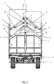
- Fig. 1 1 comprises a chassis 2 and a loading platform 3 arranged above the chassis 2. At the front and rear ends, the loading platform 3 is delimited by one end wall 4 in each case. In lateral, ie transverse direction of the transport vehicle, the loading platform 3 is also bounded on both sides by side walls 5, provided that they are in their closed positions, as shown in the Fig. 1 is shown.
- each of the side walls 5 can be moved in a variety of open positions. This is done in each case by means of two first opening devices 6 and two second opening devices 7 for each of the side walls 5, wherein in each case a first opening device 6 and a second opening device 7 in the region of the front end and in the region of the rear end of each side wall 5 are arranged. All opening device 6, 7 are designed as hydraulic cylinders.
- the side walls 5 are each connected by means of a first pivot joint 8 (rotatable about at least one aligned in the longitudinal direction of the transport vehicle axis) with a support arm 9, in turn by means of a second pivot 10 (rotatable around at least one axis aligned in the longitudinal direction of the transport vehicle) is connected to a support structure 11.
- the support structure 11 is designed in the form of a vertically oriented, centrally (with respect to the transverse direction of the transport vehicle) connected to the associated end wall 4 supporting beam. The connection between the support beam and the associated support arms 9 takes place at the free ends of the support beams.
- each of the support arms 9 serving as a first opening device 6 hydraulic cylinder is supported with one of its ends, while the other end, spaced from the respectively adjacent second pivot 10, is supported on the support structure 11.
- the connection between the first opening devices 6 and on the one hand the support arms 9 and on the other hand the support structures 11 is also designed to be rotatable about axes aligned in the longitudinal direction of the transport vehicle, for which purpose pivot joints 12 are provided.
- the hydraulic cylinders of the second opening devices 7 are each connected by means of a third rotary joint 13 with the associated side walls 5 and by means of a respective fourth rotary joint 14 with the associated support structures 11.
- the third pivot joints 13 spaced from the respective adjacent first pivot joints 8 and the fourth pivot joints 14 spaced from each adjacent second pivot joints 10 are arranged. It is provided that the distances between each of the first pivot 8 and the third pivot 13 on the one hand and the second pivot 10 and the fourth pivot 14 on the other hand are substantially identical.
- a parallelogram kinematic for the side walls 5 is achieved in a method by means of the first opening devices 6 (and fully retracted hydraulic cylinders of the second opening devices).
- the inventive design of the transport vehicle allows variable opening of the side walls 5 in order to load and unload the pallet 3.
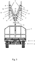
- various open positions shown in the side walls in an opening to a fully open position see. Fig. 5 ) can be moved.
- a first opening position which is achieved by operating the first opening devices 6, that is, a partial extension of the corresponding hydraulic cylinder.
- the side walls 5, starting from the closed position according to the Fig. 1 in which they are aligned substantially vertically and all hydraulic cylinders are fully retracted, are moved in an operation of the first opening devices substantially purely translational, said movements be guided according to the parallelogram kinematics.
- These parallelogram kinematics also lead to the fact that the side walls 5 are moved in the process not only in the vertical direction but also in the transverse direction.
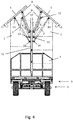
- the Fig. 4 shows how starting from the intermediate end position according to the Fig. 3 the hydraulic cylinders of the second opening devices 7 are extended, whereby the side walls 5 are pivoted about the rotational axes formed by second pivot joints 10.
- the side walls 5 are moved in this way as far as possible from the space above the loading platform, so that the transport vehicle can be loaded as high as possible with the cargo 1. This can be done, for example, up to a legally permissible maximum height of 4 m.
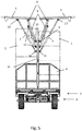
- the Fig. 5 shows the orientation of the side walls 5 in the fully open position, in which all the hydraulic cylinders of the first opening devices 6 and the second opening devices 7 are fully extended.
- the side walls 5 have an approximately horizontal orientation.
- a last section of the movements of the side walls into the completely closed position and a first section of the movements of the side walls out of the fully closed position are carried out exclusively by a method by means of the first opening devices 6.
- an automatic locking and unlocking of a locking device for the side walls 5 can be realized by, for example, on the side walls 5 arranged locking bolts in this last or first portion of the movements of the side walls in or out of associated locking grooves.
- Another advantage of the transport vehicle is that by the specific embodiment of the of the support arms 9, the hydraulic cylinders of the first opening device 6 and the second opening device 7 and the Support structure trained mechanism is ensured that in case of failure of the hydraulic cylinder driving hydraulic system, the side walls 5, provided that in the closed position corresponding to Fig. 1 are positioned, remain closed and can not open automatically. In the event of failure of the hydraulic system with the side walls 5 open, the mechanism also causes the sidewalls to be moved to the closed positions under the influence of gravity.
Landscapes
- Engineering & Computer Science (AREA)
- Mechanical Engineering (AREA)
- Chemical & Material Sciences (AREA)
- Combustion & Propulsion (AREA)
- Transportation (AREA)
- Loading Or Unloading Of Vehicles (AREA)
- Body Structure For Vehicles (AREA)
- Auxiliary Methods And Devices For Loading And Unloading (AREA)
Description
Die Erfindung betrifft ein Transportfahrzeug für Stückgut, das insbesondere in Form von gepressten Ballen, wie beispielsweise Heu-, Stroh- oder Silageballen, vorliegen kann.The invention relates to a transport vehicle for general cargo, which may be present in particular in the form of pressed bales, such as hay, straw or silage bales.
Aus der
Von Lastkraftwagen sind zudem sogenannte Flügel-Aufbauteile bekannt (vgl.
Die
Die
Die
Ausgehend von diesem Stand der Technik hat der Erfindung die Aufgabe zugrunde gelegen, ein Transportfahrzeug für Stückgut anzugeben, das sich vorteilhaft be- und entladen lässt. Insbesondere soll das Transportfahrzeug ein vorteilhaftes Beladen des Stückguts mit unterschiedlichen Beladungshöhen ermöglichen sowie auch in beengten Platzverhältnissen be- und entladbar sein.Based on this prior art, the invention has the object to provide a transport vehicle for parcel, which can be loaded and unloaded advantageous. In particular, the transport vehicle is an advantageous loading of the To enable general cargo with different loading heights as well as being able to be loaded and unloaded in confined spaces.
Diese Aufgabe wird mittels eines Transportfahrzeugs gemäß dem Anspruch 1 gelöst. Vorteilhafte Ausgestaltungen davon sind Gegenstand der abhängigen Ansprüche und ergeben sich aus der nachfolgenden Beschreibung der Erfindung.This object is achieved by means of a transport vehicle according to
Der Erfindung liegt der Gedanke zugrunde, die Beladbarkeit eines Transportfahrzeugs dadurch zu verbessern, dass eine Öffnungsbewegung der Seitenwände (bis in eine vollständig geöffnete Stellung), die sowohl ein Anheben als auch ein Verschwenken in Richtung einer horizontalen Ausrichtung umfasst, in diese beiden Teilbewegungen unterteilt wird und diese Teilbewegungen nicht zwingend gleichzeitig erfolgen müssen.The invention is based on the idea to improve the loadability of a transport vehicle in that an opening movement of the side walls (to a fully open position), which includes both lifting and pivoting in the direction of a horizontal orientation, is divided into these two partial movements and these partial movements do not necessarily have to occur simultaneously.
Erfindungsgemäß ist ein Transportfahrzeug für Stückgut, insbesondere in Form von gepressten Ballen, wie beispielsweise Heu-, Stroh- oder Silageballen, mit einer Ladeplattform, einer vorderen Stirnwand und/oder einer hinteren Stirnwand sowie mindestens einer Seitenwand, die vorzugsweise in einer die Ladeplattform begrenzenden, geschlossenen Stellung eine vertikale Ausrichtung aufweist, vorgesehen. Die Seitenwand ist mittels einer ersten Öffnungsvorrichtung zunächst in Hochrichtung des Transportfahrzeugs verfahrbar und anschließend mittels einer zweiten Öffnungsvorrichtung um eine in Längsrichtung des Transportfahrzeugs ausgerichtete Achse (nach außen) verschwenkbar. Dazu ist eine mit der vorderen Stirnwand und/oder der hinteren Stirnwand verbundene Tragstruktur vorgesehen, an der drehbeweglich ein Tragarm für die Seitenwand befestigt ist, wobei der Tragarm drehbeweglich mit der Seitenwand verbunden und die erste Öffnungsvorrichtung zwischen der Tragstruktur und dem Tragarm abgestützt ist. Weiterhin ist die zweite Öffnungsvorrichtung drehbeweglich an der Tragstruktur und der Seitenwand befestigt, wobei die Abstände zwischen den Drehachsen der drehbaren Befestigungen des Tragarms und der zweiten Öffnungsvorrichtung an einerseits der Tragstruktur und andererseits der Seitenwand gleich sind
Das Verfahren in Hochrichtung kann vorzugsweise rein translatorisch erfolgen und/oder das Verschwenken als reine Rotation ausführbar sein. Zudem kann das Verfahren der Seitenwand gegebenenfalls bis zum Erreichen einer Zwischenendstellung erfolgen. Dabei wird unter "Zwischenendstellung" verstanden, dass kein weiteres Verfahren in Hochrichtung mehr möglich ist.According to the invention, a transport vehicle for piece goods, in particular in the form of pressed bales, such as hay, straw or silage bales, with a loading platform, a front end wall and / or a rear end wall and at least one side wall, preferably in a loading platform limiting, closed position has a vertical orientation provided. The side wall is initially movable in the vertical direction of the transport vehicle by means of a first opening device and can then be pivoted (outwardly) by means of a second opening device about an axis aligned in the longitudinal direction of the transport vehicle. For this purpose, a support structure connected to the front end wall and / or the rear end wall is provided on which a support arm for the side wall is rotatably mounted, wherein the support arm rotatably connected to the side wall and the first opening device between the support structure and the support arm is supported. Furthermore, the second opening device is rotatably mounted on the support structure and the side wall, wherein the distances between the axes of rotation of the rotatable fasteners of the support arm and the second opening device on the one hand the support structure and on the other hand, the side wall are the same
The process in the vertical direction can preferably be purely translatory and / or pivoting can be carried out as pure rotation. In addition, the method of the side wall may optionally be done until reaching an intermediate end position. In this case, "intermediate end position" means that no further method in the vertical direction is possible any more.
Erfindungsgemäß ist nicht erforderlich, dass für ein Öffnen der Seitenwand immer zunächst ein Verfahren in Hochrichtung und anschließend ein Verschwenken der Seitenwand, insbesondere bis in eine vollständig geöffnete Stellung, erfolgen muss. Erfindungswesentlich ist lediglich die konstruktive Ausgestaltung des Transportwagens derart, dass eine solche Bewegungsabfolge möglich beziehungsweise ausführbar ist.According to the invention, it is not necessary for opening the side wall always to firstly carry out a method in the vertical direction and then pivot the side wall, in particular to a fully open position. Essential to the invention is only the structural design of the trolley such that such a sequence of movements is possible or feasible.
Das erfindungsgemäße Transportfahrzeug kann vorzugsweise zwei Seitenwände aufweisen, von denen zudem bevorzugt beide entsprechend zu öffnen sind. Dadurch kann eine Beladbarkeit von beiden Seiten ermöglicht werden.The transport vehicle according to the invention may preferably have two side walls, of which preferably both are to be opened accordingly. This can be a loadability of both sides are possible.
Ein erfindungsgemäßes Transportfahrzeug kann sich dadurch auszeichnen, dass der seitliche Raumbedarf zum Öffnen der Seitenwand in Bodennähe reduziert ist.An inventive transport vehicle can be characterized in that the lateral space required for opening the side wall near the bottom is reduced.
Besonders gering kann der seitliche Raumbedarf sein, wenn, wie grundsätzlich bevorzugt vorgesehen, die Seitenwand bei dem Verfahren in Hochrichtung auch in Richtung einer (von der Fahrzeuglängsachse und der Fahrzeughochachse definierten) Längshochebene des Transportfahrzeugs, d.h. in Richtung der Fahrzeugmitte (bezogen auf die Querrichtung) des Transportfahrzeugs, bewegt wird.The lateral space requirement may be particularly low if, as is basically preferred, the side wall in the vertical direction also extends in the direction of a longitudinal plane of the transport vehicle (defined by the vehicle longitudinal axis and the vehicle vertical axis). in the direction of the vehicle center (with respect to the transverse direction) of the transport vehicle is moved.
Besonders vorteilhaft be- und entladbar ist das erfindungsgemäße Transportfahrzeug, wenn die erste Öffnungsvorrichtung und die zweite Öffnungsvorrichtung voneinander unabhängig betätigbar sind. Dadurch kann eine besonders variable Be- und Entladbarkeit des Transportfahrzeugs erreicht und insbesondere eine möglichst exakte Anpassung der Öffnungsbewegung der Seitenwand an den seitlich und oberhalb des Transportfahrzeugs vorliegenden Raum ermöglicht werden. So kann beispielsweise vorgesehen sein, dass bei sehr beengten seitlichen Platzverhältnissen lediglich ein Verfahren der Seitenwand in Hochrichtung und kein Verschwenken vorgenommen wird. Ist dieses Verfahren in Hochrichtung zudem mit einem Bewegen der Seitenwand in Richtung der Fahrzeugmitte verbunden, kann gegebenenfalls noch ein Verschwenken bis zur weitestmöglichen Ausnutzung des seitlich zur Verfügung stehenden Raums möglich sein. Andererseits kann auch vorgesehen sein, dass bei einem nur sehr kleinen zur Verfügung stehenden Raum oberhalb des Transportfahrzeugs die Seitenwand nur verschwenkt oder erst verschwenkt und anschließend ein Stück weit in Hochrichtung verfahren wird.The transport vehicle according to the invention can be loaded and unloaded in a particularly advantageous manner if the first opening device and the second opening device can be actuated independently of one another. As a result, a particularly variable loadability and unloadability of the transport vehicle can be achieved and, in particular, a most exact adaptation of the opening movement of the side wall to the space available at the side and above the transport vehicle can be made possible. For example, it may be provided that in very tight lateral space conditions only a process of the side wall in the vertical direction and no pivoting is made. If this method is also connected in the vertical direction with a movement of the side wall in the direction of the center of the vehicle, a pivoting may possibly still be possible until the greatest possible utilization of the space available at the side. On the other hand, it can also be provided that with only a very small available space above the transport vehicle, the side wall only pivoted or pivoted first and then a piece is moved far in the vertical direction.
Die erste Öffnungsvorrichtung und/oder die zweite Öffnungsvorrichtung kann/können vorzugsweise mindestens einen Hydraulik- oder Pneumatikzylinder umfassen. Diese zeichnen sich durch einen vergleichsweise geringen Platzbedarf bei gleichzeitig hoher Leistungsfähigkeit aus. Zudem kann für deren Betrieb auf eine häufig bereits bei Nutzfahrzeugen vorhandene hydraulische oder pneumatische Druckquelle zurückgegriffen werden. Möglich sind aber auch andere Ausgestaltungen der Öffnungsvorrichtung(en), insbesondere mit einem elektromotorischen Antrieb, wie beispielsweise in Form einer Spindel oder eines anderen elektromotorischen Linearantriebs.The first opening device and / or the second opening device may preferably comprise at least one hydraulic or pneumatic cylinder. These are characterized by a comparatively small footprint while maintaining high performance. In addition, they can be used for their operation on a hydraulic or pneumatic pressure source that is often already available in commercial vehicles. However, other embodiments of the opening device (s) are possible, in particular with an electromotive drive, such as, for example, in the form of a spindle or another electromotive linear drive.
Um eine vorteilhafte Be- und Entladbarkeit des Transportfahrzeugs zu erreichen, kann vorzugsweise vorgesehen sein, dass die Seitenwand mittels der zweiten Öffnungsvorrichtung zumindest bis in eine horizontale Ausrichtung verschwenkbar ist.In order to achieve an advantageous loading and unloading of the transport vehicle, it can preferably be provided that the side wall can be pivoted by means of the second opening device at least up to a horizontal orientation.
Die Tragstruktur eines erfindungsgemäßen Transportfahrzeugs kann sich nach oben über die vordere Stirnwand und/oder die hintere Stirnwand hinaus erstrecken, um eine gewünschte Beladungshöhe für das Transportfahrzeug zu erreichen, ohne die vordere und/oder hintere Stirnwand selbst entsprechend hoch ausbilden zu müssen.The support structure of a transport vehicle according to the invention may extend upwards beyond the front end wall and / or the rear end wall in order to achieve a desired loading height for the transport vehicle, without having to design the front and / or rear end wall itself correspondingly high.
Zudem kann die Tragstruktur in Querrichtung des Transportfahrzeugs mittig mit der vorderen Stirnwand und/oder der hinteren Stirnwand verbunden sein, was insbesondere dann, wenn zwei entsprechend zu öffnende Seitenwände vorgesehen sind, konstruktive Vorteile aufweisen kann.In addition, the support structure in the transverse direction of the transport vehicle may be centrally connected to the front end wall and / or the rear end wall, which may have constructive advantages, in particular when two correspondingly openable side walls are provided.
Bei einem erfindungsgemäßen Transportfahrzeug ist die erste Öffnungsvorrichtung zwischen der Tragstruktur und dem Tragarm abgestützt, während die zweite Öffnungsvorrichtung zwischen der Tragstruktur und der Seitenwand abgestützt ist. Dadurch können auf konstruktiv einfache Weise die von den beiden Öffnungsvorrichtungen bewirkten, unterschiedlichen Bewegungen der Seitenwand realisiert werden, während sich beide Öffnungsvorrichtungen vorteilhaft jeweils an der Tragstruktur abstützen.In a transport vehicle according to the invention, the first opening device between the support structure and the support arm is supported, while the second opening device between the support structure and the side wall is supported. This can be realized in a structurally simple manner caused by the two opening devices, different movements of the side wall, while both opening devices are advantageously supported respectively on the support structure.
Weiterhin ist vorgesehen, dass die Abstände zwischen den Drehachsen der drehbaren Befestigungen des Tragarms und der zweiten Öffnungsvorrichtung an einerseits der Tragstruktur und andererseits der Seitenwand identisch sind. Dadurch kann gegebenenfalls erreicht werden, dass die Seitenwand bei dem Verfahren in Hochrichtung rein translatorisch bewegt wird.It is further provided that the distances between the axes of rotation of the rotatable fasteners of the support arm and the second opening device are identical on the one hand the support structure and on the other hand, the side wall. As a result, if necessary, it can be achieved that the side wall is moved purely translationally in the vertical direction in the process.
In einer bevorzugten Ausgestaltung des erfindungsgemäßen Transportfahrzeugs kann zudem noch eine Verriegelungsvorrichtung für die Seitenwand vorgesehen sein, durch die ein ungewolltes Öffnen in der geschlossenen Stellung, insbesondere in Folge einer seitlich gerichteten Belastung durch das Stückgut, verhindert wird. Eine konstruktiv einfache und funktional vorteilhafte Ausgestaltung einer solchen Verriegelungsvorrichtung kann erhalten werden, wenn diese durch das Verfahren der Seitenwand selbsttätig ent- und/oder verriegelbar ausgeführt ist.In a preferred embodiment of the transport vehicle according to the invention may also be provided a locking device for the side wall, by the unintentional opening in the closed position, in particular as a result of a laterally directed load by the cargo is prevented. A structurally simple and functionally advantageous embodiment of such a locking device can be obtained if this is done by the process of the side wall automatically unlocked and / or lockable.
Die Erfindung wird nachfolgend anhand eines in den Zeichnungen dargestellten Ausführungsbeispiels näher erläutert. In den Zeichnungen zeigt:
- Fig. 1
- in einer Ansicht von hinten ein erfindungsgemäßes Transportfahrzeug mit den Seitenwänden in geschlossener Stellung;
- Fig. 2
- das Transportfahrzeug gemäß der
Fig. 1 in einer ersten Öffnungsstellung; - Fig. 3
- das Transportfahrzeug gemäß der
Fig. 1 in einer zweiten Öffnungsstellung; - Fig. 4
- das Transportfahrzeug gemäß der
Fig. 1 in einer dritten Öffnungsstellung; und - Fig. 5
- das Transportfahrzeug gemäß der
Fig. 1 in einer vierten Öffnungsstellung.
- Fig. 1
- in a view from behind a transport vehicle according to the invention with the side walls in the closed position;
- Fig. 2
- the transport vehicle according to the
Fig. 1 in a first open position; - Fig. 3
- the transport vehicle according to the
Fig. 1 in a second open position; - Fig. 4
- the transport vehicle according to the
Fig. 1 in a third open position; and - Fig. 5
- the transport vehicle according to the
Fig. 1 in a fourth open position.
Das in
Zum Be- und Entladen der Ladeplattform 3 und damit des Transportfahrzeugs kann jede der Seitenwände 5 in eine Vielzahl von Öffnungsstellungen bewegt werden. Dies erfolgt jeweils mittels zwei ersten Öffnungsvorrichtungen 6 und zwei zweiten Öffnungsvorrichtungen 7 für jede der Seitenwände 5, wobei jeweils eine erste Öffnungsvorrichtung 6 und eine zweite Öffnungsvorrichtung 7 im Bereich des vorderen Endes sowie im Bereich des hinteren Endes jeder Seitenwand 5 angeordnet sind. Alle Öffnungsvorrichtung 6, 7 sind als Hydraulikzylinder ausgeführt.For loading and unloading the
Sowohl im Bereich des vorderen Endes als auch des hinteren Endes des Transportfahrzeugs sind die Seitenwände 5 jeweils mittels eines ersten Drehgelenks 8 (drehbar um zumindest eine in Längsrichtung des Transportfahrzeugs ausgerichtete Achse) mit einem Tragarm 9 verbunden, der wiederum mittels eines zweiten Drehgelenks 10 (drehbar um zumindest eine in Längsrichtung des Transportfahrzeugs ausgerichtete Achse) mit einer Tragstruktur 11 verbunden ist. Die Tragstruktur 11 ist in Form eines vertikal ausgerichteten, mittig (bezüglich der Querrichtung des Transportfahrzeugs) mit der dazugehörigen Stirnwand 4 verbundenen Tragbalkens ausgeführt. Die Verbindung zwischen den Tragbalken und den dazugehörigen Tragarmen 9 erfolgt an den freien Enden der Tragbalken.Both in the region of the front end and the rear end of the transport vehicle, the
An jedem der Tragarme 9 stützt sich ein als erste Öffnungsvorrichtung 6 dienender Hydraulikzylinder mit einem seiner Enden ab, während das andere Ende, beabstandet von dem jeweils benachbarten zweiten Drehgelenk 10, an der Tragstruktur 11 abgestützt ist. Dabei ist die Verbindung zwischen den ersten Öffnungsvorrichtungen 6 und einerseits den Tragarmen 9 sowie andererseits den Tragstrukturen 11 ebenfalls um in Längsrichtung des Transportfahrzeugs ausgerichtete Achsen drehbar ausgeführt, wozu entsprechende Drehgelenke 12 vorgesehen sind.At each of the
Die Hydraulikzylinder der zweiten Öffnungsvorrichtungen 7 sind jeweils mittels eines dritten Drehgelenks 13 mit den dazugehörigen Seitenwänden 5 und mittels jeweils eines vierten Drehgelenks 14 mit den dazugehörigen Tragstrukturen 11 verbunden. Dabei sind die dritten Drehgelenke 13 beabstandet zu den jeweils benachbarten ersten Drehgelenken 8 und die vierten Drehgelenke 14 beabstandet zu den jeweils benachbarten zweiten Drehgelenken 10 angeordnet. Vorgesehen ist, dass die Abstände zwischen jeweils dem ersten Drehgelenk 8 und dem dritten Drehgelenk 13 einerseits und dem zweiten Drehgelenk 10 und dem vierten Drehgelenk 14 andererseits im Wesentlichen identisch sind. Dadurch wird eine ParallelogrammKinematik für die Seitenwände 5 bei einem Verfahren mittels der ersten Öffnungsvorrichtungen 6 (und vollständig eingefahrenen Hydraulikzylindern der zweiten Öffnungsvorrichtungen) erreicht.The hydraulic cylinders of the
Die erfindungsgemäße Ausgestaltung des Transportfahrzeugs ermöglicht ein variables Öffnen der Seitenwände 5, um die Ladeplatteform 3 be- und entladen zu können. Lediglich beispielhaft sind in den
Dabei ist in der
Die in der
Die
Wie sich aus den
Selbstverständlich besteht die Möglichkeit, zumindest Abschnitte dieser durch die ersten und zweiten Öffnungsvorrichtungen 6, 7 bewirkten Teilbewegungen gleichzeitig ablaufen zu lassen.Of course, it is possible to run at least portions of these caused by the first and
Vorzugsweise ist vorgesehen, dass ein letzter Abschnitt der Bewegungen der Seitenwände in die vollständig geschlossene Stellung sowie ein erster Abschnitt der Bewegungen der Seitenwände aus der vollständig geschlossenen Stellung heraus ausschließlich durch ein Verfahren mittels der ersten Öffnungsvorrichtungen 6 durchgeführt wird. Dadurch kann ein selbsttätiges Ver- und Entriegeln einer Verriegelungsvorrichtung für die Seitenwände 5 realisiert werden, indem beispielsweise an den Seitenwänden 5 angeordnete Verriegelungsbolzen bei diesem letzten beziehungsweise ersten Abschnitt der Bewegungen der Seitenwände in dazugehörige Verriegelungsnuten hinein- beziehungsweise aus diesen herausbewegt werden.It is preferably provided that a last section of the movements of the side walls into the completely closed position and a first section of the movements of the side walls out of the fully closed position are carried out exclusively by a method by means of the
Ein weiterer Vorteil des Transportfahrzeugs liegt darin, dass durch die konkrete Ausgestaltung der von den Tragarmen 9, den Hydraulikzylindern der ersten Öffnungsvorrichtung 6 und der zweiten Öffnungsvorrichtung 7 sowie der Tragstruktur ausgebildete Mechanik sichergestellt wird, dass bei einem Ausfall des die Hydraulikzylinder ansteuernden hydraulischen Systems die Seitenwände 5, sofern Sie in der geschlossenen Stellung entsprechend der
- 1.1.
- Stückgutcargo
- 2.Second
- Fahrgestellchassis
- 3.Third
- Ladeplattformloading platform
- 4.4th
- Stirnwandbulkhead
- 5.5th
- SeitenwandSide wall
- 6.6th
- erste Öffnungsvorrichtungfirst opening device
- 7.7th
- zweite Öffnungsvorrichtungsecond opening device
- 8.8th.
- erstes Drehgelenkfirst rotary joint
- 9.9th
- TragarmBeam
- 10.10th
- zweites Drehgelenksecond pivot
- 11.11th
- Tragstruktursupporting structure
- 12.12th
- Drehgelenkswivel
- 13.13th
- drittes Drehgelenkthird pivot
- 14.14th
- viertes Drehgelenkfourth swivel joint
Claims (8)
- Transport vehicle for piece goods (1) having a loading platform (3), a front end wall and/or a rear end wall (4) and at least one side wall (5), wherein the side wall (5) is first displaceable by means of a first opening device (6) in the vertical direction of the transport vehicle, and by means of a second opening device (7) is then pivotable about an axis oriented in the longitudinal direction of the transport vehicle, for which purpose a carrier structure (11) that is connected to the front end wall (4) and/or to the rear end wall (4) is provided, to which a carrier arm (9) for the side wall (5) is fastened in a rotationally movable manner, wherein the carrier arm (9) is connected to the side wall (5) in a rotationally movable manner and the first opening device (6) is supported between the carrier structure (11) and the carrier arm (9), characterised in that the second opening device (7) is fastened to the carrier structure (11) and to the side wall (5) in a rotationally movable manner, and the distances between the rotational axes of the rotatable fastenings of the carrier arm (9) and of the second opening device (7) at the carrier structure (11) on the one hand, and at the side wall (5) on the other hand, are equal.
- Transport vehicle according to claim 1, characterised in that the side wall (5) is displaceable purely translationally in at least one movement section.
- Transport vehicle according to any one of the preceding claims, characterised in that the side wall (5) has a vertical orientation in a closed position delimiting the loading platform (3).
- Transport vehicle according to any one of the preceding claims, characterised in that the side wall (5), when displaced in the vertical direction, is also moved in the transverse direction of the transport vehicle.
- Transport vehicle according to any one of the preceding claims, characterised in that the side wall (5) is pivotable into a horizontal orientation.
- Transport vehicle according to any one of the preceding claims, characterised in that the carrier structure (11) extends upwards beyond the front end wall (4) and/or the rear end wall (4).
- Transport vehicle according to any one of the preceding claims, characterised in that the carrier structure (11) is connected to the front end wall (4) and/or to the rear end wall (4) centrally in the transverse direction of the transport vehicle.
- Transport vehicle according to any one of the preceding claims, characterised by a locking device for the side wall (5),which locking device can be locked and/or unlocked by a displacement of the side wall (5) by means of the opening device (6, 7).
Priority Applications (3)
| Application Number | Priority Date | Filing Date | Title |
|---|---|---|---|
| SI201530326T SI2944490T1 (en) | 2014-05-16 | 2015-05-06 | Transport vehicle for piece goods |
| PL15166608T PL2944490T3 (en) | 2014-05-16 | 2015-05-06 | Transport vehicle for piece goods |
| HRP20181215TT HRP20181215T1 (en) | 2014-05-16 | 2018-07-30 | Transport vehicle for piece goods |
Applications Claiming Priority (1)
| Application Number | Priority Date | Filing Date | Title |
|---|---|---|---|
| DE202014102306.2U DE202014102306U1 (en) | 2014-05-16 | 2014-05-16 | Transport vehicle for general cargo |
Publications (2)
| Publication Number | Publication Date |
|---|---|
| EP2944490A1 EP2944490A1 (en) | 2015-11-18 |
| EP2944490B1 true EP2944490B1 (en) | 2018-07-04 |
Family
ID=51015462
Family Applications (1)
| Application Number | Title | Priority Date | Filing Date |
|---|---|---|---|
| EP15166608.8A Active EP2944490B1 (en) | 2014-05-16 | 2015-05-06 | Transport vehicle for piece goods |
Country Status (8)
| Country | Link |
|---|---|
| US (1) | US9545959B2 (en) |
| EP (1) | EP2944490B1 (en) |
| DE (1) | DE202014102306U1 (en) |
| DK (1) | DK2944490T3 (en) |
| HR (1) | HRP20181215T1 (en) |
| HU (1) | HUE039825T2 (en) |
| PL (1) | PL2944490T3 (en) |
| SI (1) | SI2944490T1 (en) |
Families Citing this family (5)
| Publication number | Priority date | Publication date | Assignee | Title |
|---|---|---|---|---|
| US20150334921A1 (en) * | 2014-05-23 | 2015-11-26 | Vermeer Manufacturing Company | Apparatus and methods for containing bales on a transport vehicle |
| DK3326861T3 (en) | 2016-11-23 | 2020-10-19 | H P Beck & Soehne Ag | Load securing device |
| DE102019218721A1 (en) * | 2019-12-02 | 2021-06-02 | Brose Fahrzeugteile SE & Co. Kommanditgesellschaft, Coburg | Console element for a vehicle |
| AT524320B1 (en) * | 2020-10-23 | 2022-05-15 | Avl List Gmbh | VEHICLE WITH ONE DOOR ARRANGEMENT |
| DE202021103475U1 (en) | 2021-06-30 | 2021-09-02 | Erik Schiefer | Bale transport trolley |
Citations (1)
| Publication number | Priority date | Publication date | Assignee | Title |
|---|---|---|---|---|
| WO2010115226A1 (en) * | 2009-04-09 | 2010-10-14 | Strasser Johann Sen | Apparatus for transferring a wall of a transport container and transport container therewith |
Family Cites Families (9)
| Publication number | Priority date | Publication date | Assignee | Title |
|---|---|---|---|---|
| CH676953A5 (en) | 1988-06-14 | 1991-03-28 | Gangloff Ag Carrosserie | |
| DE9207826U1 (en) * | 1992-06-11 | 1992-11-05 | Maier, Michael, 8341 Dietersburg | Device for opening and closing load compartment covers from the side |
| AU711371B2 (en) * | 1996-03-21 | 1999-10-14 | Johann Strasser | Side wall for the body of a vehicle |
| DE10015545C2 (en) * | 2000-03-30 | 2003-12-04 | Mms Multimodalsysteme Ag Pfaef | Swap bodies |
| DE202007019318U1 (en) | 2007-05-03 | 2011-12-06 | Georg Krassort | Transport trolley for agricultural goods in particular |
| DE102008049135A1 (en) | 2008-09-26 | 2010-04-08 | Gisela Weber | Hydraulic system for adjusting blade assembly unit of heavy goods vehicle, has hydraulic controlling unit with hydraulic pump and hydraulic valves |
| DE202012005798U1 (en) | 2012-06-14 | 2012-07-19 | Fahrzeugbau Heinz Böse GmbH | Structure for a truck, a trailer, a Absetzcontainer, a swap, a semi-trailer or the like |
| HUE031025T2 (en) | 2013-07-10 | 2017-06-28 | Fliegl Jun Josef | Transport vehicle for piece goods |
| US9193397B2 (en) * | 2013-12-17 | 2015-11-24 | GM Global Technology Operations LLC | Lateral expanding cargo bed |
-
2014
- 2014-05-16 DE DE202014102306.2U patent/DE202014102306U1/en not_active Expired - Lifetime
-
2015
- 2015-05-06 EP EP15166608.8A patent/EP2944490B1/en active Active
- 2015-05-06 DK DK15166608.8T patent/DK2944490T3/en active
- 2015-05-06 PL PL15166608T patent/PL2944490T3/en unknown
- 2015-05-06 SI SI201530326T patent/SI2944490T1/en unknown
- 2015-05-06 HU HUE15166608A patent/HUE039825T2/en unknown
- 2015-05-13 US US14/710,664 patent/US9545959B2/en active Active
-
2018
- 2018-07-30 HR HRP20181215TT patent/HRP20181215T1/en unknown
Patent Citations (1)
| Publication number | Priority date | Publication date | Assignee | Title |
|---|---|---|---|---|
| WO2010115226A1 (en) * | 2009-04-09 | 2010-10-14 | Strasser Johann Sen | Apparatus for transferring a wall of a transport container and transport container therewith |
Also Published As
| Publication number | Publication date |
|---|---|
| SI2944490T1 (en) | 2018-09-28 |
| HUE039825T2 (en) | 2019-02-28 |
| US9545959B2 (en) | 2017-01-17 |
| DE202014102306U1 (en) | 2014-06-06 |
| US20150329150A1 (en) | 2015-11-19 |
| PL2944490T3 (en) | 2018-12-31 |
| EP2944490A1 (en) | 2015-11-18 |
| HRP20181215T1 (en) | 2018-10-05 |
| DK2944490T3 (en) | 2018-10-15 |
Similar Documents
| Publication | Publication Date | Title |
|---|---|---|
| EP2944490B1 (en) | Transport vehicle for piece goods | |
| EP3147160B1 (en) | Storage structure for a commercial vehicle, in particular a heavy goods vehicle | |
| DE3233669A1 (en) | SUPPORT ARRANGEMENT FOR A LIFT, OR STAGE FOR TRUCKS AND THE LIKE | |
| DE102010024687A1 (en) | Folding driver's roof | |
| DE102010027716A1 (en) | Commercial vehicle, particularly articulated train, has bodywork which is height-adjustable between position and another position | |
| DE202012104195U1 (en) | Commercial vehicle body with at least one side tarpaulin | |
| EP4043644A1 (en) | Operator's cab with protective screen | |
| DE102010030812A1 (en) | Covering device for tilting bridge-type transport container of e.g. three sided dump truck vehicle, has operating device that does not laterally overlap at surface such that plate is not folded when tarpaulin is found in covering position | |
| EP2810822B1 (en) | Transfer trolley | |
| DE2849194C2 (en) | ||
| EP3173286B1 (en) | Transport vehicle for piece goods | |
| EP2676824B1 (en) | Superstructure for conveying goods | |
| DE202013105357U1 (en) | Safety device for a truck | |
| DE102005042243B4 (en) | Foldable transport container | |
| EP1616778A2 (en) | Broad load transporting vehicle | |
| DE1111521B (en) | Trucks, especially for bulk goods | |
| DE102015111842B4 (en) | Container superstructure | |
| EP0849115B1 (en) | Loading and unloading device for transport vehicle | |
| DE102014208166A1 (en) | Sliding roof structure | |
| EP2684782B1 (en) | Assembly for conveying goods | |
| DE202007014067U1 (en) | Bulk commercial vehicle | |
| DE2261934A1 (en) | SIDE WALL | |
| EP3000687B1 (en) | Roof frame for a canvas cover of a transport vehicle | |
| DE2218828A1 (en) | BACK PANEL AND COVER WITH DEPENDENT MOVEMENT ON TRUCKS | |
| DE102008007639B4 (en) | Loading structure for a truck |
Legal Events
| Date | Code | Title | Description |
|---|---|---|---|
| PUAI | Public reference made under article 153(3) epc to a published international application that has entered the european phase |
Free format text: ORIGINAL CODE: 0009012 |
|
| AK | Designated contracting states |
Kind code of ref document: A1 Designated state(s): AL AT BE BG CH CY CZ DE DK EE ES FI FR GB GR HR HU IE IS IT LI LT LU LV MC MK MT NL NO PL PT RO RS SE SI SK SM TR |
|
| AX | Request for extension of the european patent |
Extension state: BA ME |
|
| 17P | Request for examination filed |
Effective date: 20151102 |
|
| RBV | Designated contracting states (corrected) |
Designated state(s): AL AT BE BG CH CY CZ DE DK EE ES FI FR GB GR HR HU IE IS IT LI LT LU LV MC MK MT NL NO PL PT RO RS SE SI SK SM TR |
|
| STAA | Information on the status of an ep patent application or granted ep patent |
Free format text: STATUS: EXAMINATION IS IN PROGRESS |
|
| 17Q | First examination report despatched |
Effective date: 20170323 |
|
| GRAP | Despatch of communication of intention to grant a patent |
Free format text: ORIGINAL CODE: EPIDOSNIGR1 |
|
| STAA | Information on the status of an ep patent application or granted ep patent |
Free format text: STATUS: GRANT OF PATENT IS INTENDED |
|
| INTG | Intention to grant announced |
Effective date: 20180216 |
|
| GRAS | Grant fee paid |
Free format text: ORIGINAL CODE: EPIDOSNIGR3 |
|
| GRAA | (expected) grant |
Free format text: ORIGINAL CODE: 0009210 |
|
| STAA | Information on the status of an ep patent application or granted ep patent |
Free format text: STATUS: THE PATENT HAS BEEN GRANTED |
|
| AK | Designated contracting states |
Kind code of ref document: B1 Designated state(s): AL AT BE BG CH CY CZ DE DK EE ES FI FR GB GR HR HU IE IS IT LI LT LU LV MC MK MT NL NO PL PT RO RS SE SI SK SM TR |
|
| REG | Reference to a national code |
Ref country code: GB Ref legal event code: FG4D Free format text: NOT ENGLISH |
|
| REG | Reference to a national code |
Ref country code: CH Ref legal event code: EP |
|
| REG | Reference to a national code |
Ref country code: AT Ref legal event code: REF Ref document number: 1014121 Country of ref document: AT Kind code of ref document: T Effective date: 20180715 |
|
| REG | Reference to a national code |
Ref country code: IE Ref legal event code: FG4D Free format text: LANGUAGE OF EP DOCUMENT: GERMAN |
|
| REG | Reference to a national code |
Ref country code: HR Ref legal event code: TUEP Ref document number: P20181215 Country of ref document: HR |
|
| REG | Reference to a national code |
Ref country code: DE Ref legal event code: R096 Ref document number: 502015004897 Country of ref document: DE |
|
| REG | Reference to a national code |
Ref country code: RO Ref legal event code: EPE |
|
| REG | Reference to a national code |
Ref country code: NL Ref legal event code: FP |
|
| REG | Reference to a national code |
Ref country code: HR Ref legal event code: T1PR Ref document number: P20181215 Country of ref document: HR |
|
| REG | Reference to a national code |
Ref country code: DK Ref legal event code: T3 Effective date: 20181008 |
|
| REG | Reference to a national code |
Ref country code: NO Ref legal event code: T2 Effective date: 20180704 |
|
| REG | Reference to a national code |
Ref country code: LT Ref legal event code: MG4D |
|
| REG | Reference to a national code |
Ref country code: SK Ref legal event code: T3 Ref document number: E 28572 Country of ref document: SK |
|
| PG25 | Lapsed in a contracting state [announced via postgrant information from national office to epo] |
Ref country code: FI Free format text: LAPSE BECAUSE OF FAILURE TO SUBMIT A TRANSLATION OF THE DESCRIPTION OR TO PAY THE FEE WITHIN THE PRESCRIBED TIME-LIMIT Effective date: 20180704 Ref country code: SE Free format text: LAPSE BECAUSE OF FAILURE TO SUBMIT A TRANSLATION OF THE DESCRIPTION OR TO PAY THE FEE WITHIN THE PRESCRIBED TIME-LIMIT Effective date: 20180704 Ref country code: IS Free format text: LAPSE BECAUSE OF FAILURE TO SUBMIT A TRANSLATION OF THE DESCRIPTION OR TO PAY THE FEE WITHIN THE PRESCRIBED TIME-LIMIT Effective date: 20181104 Ref country code: RS Free format text: LAPSE BECAUSE OF FAILURE TO SUBMIT A TRANSLATION OF THE DESCRIPTION OR TO PAY THE FEE WITHIN THE PRESCRIBED TIME-LIMIT Effective date: 20180704 Ref country code: BG Free format text: LAPSE BECAUSE OF FAILURE TO SUBMIT A TRANSLATION OF THE DESCRIPTION OR TO PAY THE FEE WITHIN THE PRESCRIBED TIME-LIMIT Effective date: 20181004 Ref country code: LT Free format text: LAPSE BECAUSE OF FAILURE TO SUBMIT A TRANSLATION OF THE DESCRIPTION OR TO PAY THE FEE WITHIN THE PRESCRIBED TIME-LIMIT Effective date: 20180704 Ref country code: GR Free format text: LAPSE BECAUSE OF FAILURE TO SUBMIT A TRANSLATION OF THE DESCRIPTION OR TO PAY THE FEE WITHIN THE PRESCRIBED TIME-LIMIT Effective date: 20181005 |
|
| PG25 | Lapsed in a contracting state [announced via postgrant information from national office to epo] |
Ref country code: ES Free format text: LAPSE BECAUSE OF FAILURE TO SUBMIT A TRANSLATION OF THE DESCRIPTION OR TO PAY THE FEE WITHIN THE PRESCRIBED TIME-LIMIT Effective date: 20180704 Ref country code: LV Free format text: LAPSE BECAUSE OF FAILURE TO SUBMIT A TRANSLATION OF THE DESCRIPTION OR TO PAY THE FEE WITHIN THE PRESCRIBED TIME-LIMIT Effective date: 20180704 Ref country code: AL Free format text: LAPSE BECAUSE OF FAILURE TO SUBMIT A TRANSLATION OF THE DESCRIPTION OR TO PAY THE FEE WITHIN THE PRESCRIBED TIME-LIMIT Effective date: 20180704 |
|
| REG | Reference to a national code |
Ref country code: HU Ref legal event code: AG4A Ref document number: E039825 Country of ref document: HU |
|
| REG | Reference to a national code |
Ref country code: DE Ref legal event code: R097 Ref document number: 502015004897 Country of ref document: DE |
|
| PG25 | Lapsed in a contracting state [announced via postgrant information from national office to epo] |
Ref country code: EE Free format text: LAPSE BECAUSE OF FAILURE TO SUBMIT A TRANSLATION OF THE DESCRIPTION OR TO PAY THE FEE WITHIN THE PRESCRIBED TIME-LIMIT Effective date: 20180704 |
|
| PLBE | No opposition filed within time limit |
Free format text: ORIGINAL CODE: 0009261 |
|
| STAA | Information on the status of an ep patent application or granted ep patent |
Free format text: STATUS: NO OPPOSITION FILED WITHIN TIME LIMIT |
|
| PG25 | Lapsed in a contracting state [announced via postgrant information from national office to epo] |
Ref country code: SM Free format text: LAPSE BECAUSE OF FAILURE TO SUBMIT A TRANSLATION OF THE DESCRIPTION OR TO PAY THE FEE WITHIN THE PRESCRIBED TIME-LIMIT Effective date: 20180704 |
|
| 26N | No opposition filed |
Effective date: 20190405 |
|
| REG | Reference to a national code |
Ref country code: HR Ref legal event code: ODRP Ref document number: P20181215 Country of ref document: HR Payment date: 20190530 Year of fee payment: 5 |
|
| PG25 | Lapsed in a contracting state [announced via postgrant information from national office to epo] |
Ref country code: MC Free format text: LAPSE BECAUSE OF FAILURE TO SUBMIT A TRANSLATION OF THE DESCRIPTION OR TO PAY THE FEE WITHIN THE PRESCRIBED TIME-LIMIT Effective date: 20180704 |
|
| PG25 | Lapsed in a contracting state [announced via postgrant information from national office to epo] |
Ref country code: LU Free format text: LAPSE BECAUSE OF NON-PAYMENT OF DUE FEES Effective date: 20190506 |
|
| PG25 | Lapsed in a contracting state [announced via postgrant information from national office to epo] |
Ref country code: TR Free format text: LAPSE BECAUSE OF FAILURE TO SUBMIT A TRANSLATION OF THE DESCRIPTION OR TO PAY THE FEE WITHIN THE PRESCRIBED TIME-LIMIT Effective date: 20180704 |
|
| PG25 | Lapsed in a contracting state [announced via postgrant information from national office to epo] |
Ref country code: IE Free format text: LAPSE BECAUSE OF NON-PAYMENT OF DUE FEES Effective date: 20190506 |
|
| REG | Reference to a national code |
Ref country code: HR Ref legal event code: ODRP Ref document number: P20181215 Country of ref document: HR Payment date: 20200428 Year of fee payment: 6 |
|
| PG25 | Lapsed in a contracting state [announced via postgrant information from national office to epo] |
Ref country code: PT Free format text: LAPSE BECAUSE OF FAILURE TO SUBMIT A TRANSLATION OF THE DESCRIPTION OR TO PAY THE FEE WITHIN THE PRESCRIBED TIME-LIMIT Effective date: 20181104 |
|
| REG | Reference to a national code |
Ref country code: HR Ref legal event code: ODRP Ref document number: P20181215 Country of ref document: HR Payment date: 20210429 Year of fee payment: 7 |
|
| PG25 | Lapsed in a contracting state [announced via postgrant information from national office to epo] |
Ref country code: CY Free format text: LAPSE BECAUSE OF FAILURE TO SUBMIT A TRANSLATION OF THE DESCRIPTION OR TO PAY THE FEE WITHIN THE PRESCRIBED TIME-LIMIT Effective date: 20180704 |
|
| PG25 | Lapsed in a contracting state [announced via postgrant information from national office to epo] |
Ref country code: MT Free format text: LAPSE BECAUSE OF FAILURE TO SUBMIT A TRANSLATION OF THE DESCRIPTION OR TO PAY THE FEE WITHIN THE PRESCRIBED TIME-LIMIT Effective date: 20180704 |
|
| REG | Reference to a national code |
Ref country code: HR Ref legal event code: ODRP Ref document number: P20181215 Country of ref document: HR Payment date: 20220502 Year of fee payment: 8 |
|
| PG25 | Lapsed in a contracting state [announced via postgrant information from national office to epo] |
Ref country code: MK Free format text: LAPSE BECAUSE OF FAILURE TO SUBMIT A TRANSLATION OF THE DESCRIPTION OR TO PAY THE FEE WITHIN THE PRESCRIBED TIME-LIMIT Effective date: 20180704 |
|
| PGFP | Annual fee paid to national office [announced via postgrant information from national office to epo] |
Ref country code: NL Payment date: 20220518 Year of fee payment: 8 |
|
| PGFP | Annual fee paid to national office [announced via postgrant information from national office to epo] |
Ref country code: SK Payment date: 20220502 Year of fee payment: 8 Ref country code: RO Payment date: 20220503 Year of fee payment: 8 Ref country code: NO Payment date: 20220520 Year of fee payment: 8 Ref country code: IT Payment date: 20220531 Year of fee payment: 8 Ref country code: HU Payment date: 20220426 Year of fee payment: 8 Ref country code: HR Payment date: 20220502 Year of fee payment: 8 Ref country code: GB Payment date: 20220523 Year of fee payment: 8 Ref country code: FR Payment date: 20220523 Year of fee payment: 8 Ref country code: DK Payment date: 20220523 Year of fee payment: 8 Ref country code: DE Payment date: 20220519 Year of fee payment: 8 Ref country code: CZ Payment date: 20220503 Year of fee payment: 8 |
|
| PGFP | Annual fee paid to national office [announced via postgrant information from national office to epo] |
Ref country code: SI Payment date: 20220425 Year of fee payment: 8 Ref country code: PL Payment date: 20220426 Year of fee payment: 8 Ref country code: CH Payment date: 20220523 Year of fee payment: 8 Ref country code: BE Payment date: 20220518 Year of fee payment: 8 Ref country code: AT Payment date: 20220517 Year of fee payment: 8 |
|
| REG | Reference to a national code |
Ref country code: HR Ref legal event code: PBON Ref document number: P20181215 Country of ref document: HR Effective date: 20230506 |
|
| REG | Reference to a national code |
Ref country code: DE Ref legal event code: R119 Ref document number: 502015004897 Country of ref document: DE |
|
| REG | Reference to a national code |
Ref country code: SK Ref legal event code: MM4A Ref document number: E 28572 Country of ref document: SK Effective date: 20230506 |
|
| REG | Reference to a national code |
Ref country code: NO Ref legal event code: MMEP |
|
| REG | Reference to a national code |
Ref country code: CH Ref legal event code: PL |
|
| REG | Reference to a national code |
Ref country code: DK Ref legal event code: EBP Effective date: 20230531 |
|
| REG | Reference to a national code |
Ref country code: NL Ref legal event code: MM Effective date: 20230601 |
|
| REG | Reference to a national code |
Ref country code: AT Ref legal event code: MM01 Ref document number: 1014121 Country of ref document: AT Kind code of ref document: T Effective date: 20230506 |
|
| PG25 | Lapsed in a contracting state [announced via postgrant information from national office to epo] |
Ref country code: SK Free format text: LAPSE BECAUSE OF NON-PAYMENT OF DUE FEES Effective date: 20230506 |
|
| GBPC | Gb: european patent ceased through non-payment of renewal fee |
Effective date: 20230506 |
|
| REG | Reference to a national code |
Ref country code: BE Ref legal event code: MM Effective date: 20230531 |
|
| PG25 | Lapsed in a contracting state [announced via postgrant information from national office to epo] |
Ref country code: SK Free format text: LAPSE BECAUSE OF NON-PAYMENT OF DUE FEES Effective date: 20230506 Ref country code: SI Free format text: LAPSE BECAUSE OF NON-PAYMENT OF DUE FEES Effective date: 20230507 Ref country code: RO Free format text: LAPSE BECAUSE OF NON-PAYMENT OF DUE FEES Effective date: 20230506 Ref country code: NO Free format text: LAPSE BECAUSE OF NON-PAYMENT OF DUE FEES Effective date: 20230531 Ref country code: LI Free format text: LAPSE BECAUSE OF NON-PAYMENT OF DUE FEES Effective date: 20230531 Ref country code: HU Free format text: LAPSE BECAUSE OF NON-PAYMENT OF DUE FEES Effective date: 20230507 Ref country code: HR Free format text: LAPSE BECAUSE OF NON-PAYMENT OF DUE FEES Effective date: 20230506 Ref country code: CZ Free format text: LAPSE BECAUSE OF NON-PAYMENT OF DUE FEES Effective date: 20230506 Ref country code: CH Free format text: LAPSE BECAUSE OF NON-PAYMENT OF DUE FEES Effective date: 20230531 Ref country code: AT Free format text: LAPSE BECAUSE OF NON-PAYMENT OF DUE FEES Effective date: 20230506 |
|
| PG25 | Lapsed in a contracting state [announced via postgrant information from national office to epo] |
Ref country code: NL Free format text: LAPSE BECAUSE OF NON-PAYMENT OF DUE FEES Effective date: 20230601 |
|
| REG | Reference to a national code |
Ref country code: SI Ref legal event code: KO00 Effective date: 20240228 |
|
| PG25 | Lapsed in a contracting state [announced via postgrant information from national office to epo] |
Ref country code: IT Free format text: LAPSE BECAUSE OF NON-PAYMENT OF DUE FEES Effective date: 20230506 Ref country code: DK Free format text: LAPSE BECAUSE OF NON-PAYMENT OF DUE FEES Effective date: 20230531 Ref country code: DE Free format text: LAPSE BECAUSE OF NON-PAYMENT OF DUE FEES Effective date: 20231201 Ref country code: GB Free format text: LAPSE BECAUSE OF NON-PAYMENT OF DUE FEES Effective date: 20230506 |
|
| PG25 | Lapsed in a contracting state [announced via postgrant information from national office to epo] |
Ref country code: FR Free format text: LAPSE BECAUSE OF NON-PAYMENT OF DUE FEES Effective date: 20230531 Ref country code: BE Free format text: LAPSE BECAUSE OF NON-PAYMENT OF DUE FEES Effective date: 20230531 |