EP3173286B1 - Véhicule de transport pour matériaux en vrac - Google Patents
Véhicule de transport pour matériaux en vrac Download PDFInfo
- Publication number
- EP3173286B1 EP3173286B1 EP16199147.6A EP16199147A EP3173286B1 EP 3173286 B1 EP3173286 B1 EP 3173286B1 EP 16199147 A EP16199147 A EP 16199147A EP 3173286 B1 EP3173286 B1 EP 3173286B1
- Authority
- EP
- European Patent Office
- Prior art keywords
- loading platform
- transport vehicle
- vehicle
- struts
- transverse direction
- Prior art date
- Legal status (The legal status is an assumption and is not a legal conclusion. Google has not performed a legal analysis and makes no representation as to the accuracy of the status listed.)
- Active
Links
- 230000033001 locomotion Effects 0.000 description 8
- 238000006073 displacement reaction Methods 0.000 description 4
- 230000008878 coupling Effects 0.000 description 3
- 238000010168 coupling process Methods 0.000 description 3
- 238000005859 coupling reaction Methods 0.000 description 3
- 238000003306 harvesting Methods 0.000 description 2
- 239000010902 straw Substances 0.000 description 2
- 230000003247 decreasing effect Effects 0.000 description 1
- 230000001419 dependent effect Effects 0.000 description 1
- 238000011161 development Methods 0.000 description 1
- 230000018109 developmental process Effects 0.000 description 1
Images


Classifications
-
- A—HUMAN NECESSITIES
- A01—AGRICULTURE; FORESTRY; ANIMAL HUSBANDRY; HUNTING; TRAPPING; FISHING
- A01D—HARVESTING; MOWING
- A01D90/00—Vehicles for carrying harvested crops with means for selfloading or unloading
- A01D90/02—Loading means
- A01D90/08—Loading means with bale-forming means additionally used for loading; with means for picking-up bales and transporting them into the vehicle
- A01D90/083—Round-bale trailers
-
- B—PERFORMING OPERATIONS; TRANSPORTING
- B60—VEHICLES IN GENERAL
- B60P—VEHICLES ADAPTED FOR LOAD TRANSPORTATION OR TO TRANSPORT, TO CARRY, OR TO COMPRISE SPECIAL LOADS OR OBJECTS
- B60P1/00—Vehicles predominantly for transporting loads and modified to facilitate loading, consolidating the load, or unloading
- B60P1/04—Vehicles predominantly for transporting loads and modified to facilitate loading, consolidating the load, or unloading with a tipping movement of load-transporting element
- B60P1/26—Means for controlling movement of tailboards or sideboards
-
- B—PERFORMING OPERATIONS; TRANSPORTING
- B60—VEHICLES IN GENERAL
- B60P—VEHICLES ADAPTED FOR LOAD TRANSPORTATION OR TO TRANSPORT, TO CARRY, OR TO COMPRISE SPECIAL LOADS OR OBJECTS
- B60P3/00—Vehicles adapted to transport, to carry or to comprise special loads or objects
-
- B—PERFORMING OPERATIONS; TRANSPORTING
- B60—VEHICLES IN GENERAL
- B60P—VEHICLES ADAPTED FOR LOAD TRANSPORTATION OR TO TRANSPORT, TO CARRY, OR TO COMPRISE SPECIAL LOADS OR OBJECTS
- B60P7/00—Securing or covering of load on vehicles
-
- B—PERFORMING OPERATIONS; TRANSPORTING
- B62—LAND VEHICLES FOR TRAVELLING OTHERWISE THAN ON RAILS
- B62D—MOTOR VEHICLES; TRAILERS
- B62D33/00—Superstructures for load-carrying vehicles
- B62D33/02—Platforms; Open load compartments
- B62D33/023—Sideboard or tailgate structures
- B62D33/027—Sideboard or tailgate structures movable
Definitions
- the invention relates to a transport vehicle for general cargo, in particular for bales, specified in the preamble of claim 1 Art.
- bale trucks for transporting piece goods in the form of hay or straw bales.
- the DE 40 05 429 A1 shows, for example, such a transport vehicle for piece goods, in particular for bales, which has a loading platform on which laterally a left side wall and a right side wall are arranged.
- a loading platform on which laterally a left side wall and a right side wall are arranged.
- front side and back respective end walls are provided for limiting the loading platform in the longitudinal direction.
- folding grid structure is arranged on the side and end walls of a designated Dürrfuttertive.
- this lattice structure which is referred to as a dry lining structure, can be pivoted up and down in order to be able to achieve load securing as required.
- the loading of the transport vehicle with cargo can make it relatively difficult.
- a difficulty may be to make a reliable load securing the transport vehicle once it has been loaded with cargo.
- the DE 29 01 597 A1 shows a folding structure which is mounted on a side wall of an agricultural harvesting cart.
- the structure consists of a front gate and pipe brackets, which are mounted on respective bearing angles at several superimposed longitudinal rails.
- the gate and tube yokes are pivotable about respective pivot points provided on respective pedestals.
- the bearing blocks are arranged on an upper side of the side wall of the harvesting cart.
- the transport vehicle according to the invention for piece goods comprises a loading platform on which a left side wall and a right side wall are arranged laterally.
- the transport vehicle according to the invention is characterized in that at least one of the side walls is formed completely in the form of a lattice structure having a plurality of horizontal struts which are hinged to at least two vertical struts, the lower longitudinal ends of which are pivotally mounted on the loading platform about respective pivot axes extending in the vehicle transverse direction are, so that the grid structure between an unfolded cargo securing position, in which the vertical struts extend in the vertical direction of the transport vehicles, and a folded-off loading position, in which the horizontal struts abut each other, is pivotable.
- the transport vehicle according to the invention is a bale carriage in which at least one of the side walls is designed in the form of said lattice structure and can be pivoted back and forth between the unfolded cargo securing position and the folded loading position.
- both side walls of the transport vehicle are formed in the form of the lattice structure.
- the entire lateral structure of the transport vehicle between the unfolded cargo securing position and the folded-off loading position is pivoted back and forth.
- the horizontal struts are mounted on the vertical struts such that the horizontal struts have a rotational degree of freedom about respective axes of rotation extending in the vehicle transverse direction.
- the transport vehicle according to the invention preferably comprises a locking device for locking the lattice structure or the lattice structures in a respective desired position.
- the transport vehicle can also have a lifting device for convenient folding and unfolding of the lattice structure or the lattice structures.
- the lifting device may be a hydraulic cylinder, by means of which the grid structure is pivotable up and down.
- the transport vehicle can be particularly easily loaded by the formed as a grid structure side wall is simply moved into the folded-off loading position. Thereafter, the transport vehicle can be loaded in a particularly convenient way from the side with cargo, such as hay bales or the like.
- the side wall designed as a grid structure can be folded from the folded-down loading position into the unfolded load securing position. In the load securing position can be reliably ensured that the loaded cargo does not fall laterally from the transport vehicle.
- the uppermost of the horizontal struts in the folded-off loading position in the vehicle vertical direction is flush with a loading platform top or below the loading platform top.
- the horizontal struts are attached to the vertical struts so that in the folded-off loading position, the vertical struts either flush with the loading platform top complete or even below the loading platform top are arranged.
- the loading platform of the transport vehicle can be loaded in a very simple way from the side, since no disturbing structures are in the way.
- a further advantageous embodiment of the invention provides that the transport vehicle has an adjusting device, by means of which the grid structure in the vehicle transverse direction is movable relative to the loading platform.
- the at least one side wall designed as a grid structure can thus be moved to and from the loading platform. This makes it possible in a simple manner, clamped on the loading platform piece goods, such as hay bales or the like, clamped between the two side walls, whereby a particularly reliable load securing can be achieved.
- the adjusting device comprises a positive guide, by means of which the grid structure is moved away from the loading platform on opening in the load securing position in the vehicle transverse direction to the loading platform and when folding into the loading position.
- the pivoting movement of the lattice structure is preferably positively coupled to a displacement of the lattice structure in the vehicle transverse direction, in such a way that the lattice structure is further away from the loading platform in the folded load position in the vehicle transverse direction than in the unfolded cargo securing position.
- a further advantageous embodiment of the invention provides that the positive guide has respective scenes extending in the vehicle transverse direction from an outside end area to an inside end area, by means of which respective guide elements arranged at the longitudinal ends of the vertical struts are forcibly guided, those in the unfolded load securing position on the respective inside end area and in the folded-off loading position on the respective outside End region of the scenes are arranged.
- the transport vehicle for the at least one grid structure on a sliding guide by means of which the movement coupling of the grid structure with respect to the movement in the vehicle transverse direction and the up or pivoting is accomplished.
- the movement of the grid structure in the vehicle transverse direction for load securing can be achieved in a particularly simple and reliable manner.
- a user of the transport vehicle does not have to actively move the at least one side wall designed as a grid structure in the vehicle transverse direction, because this happens automatically when folding up and down the sidewall formed as a grid structure.
- the adjusting device has a hydraulic adjusting mechanism, by means of which the grid structure in the vehicle transverse direction is movable relative to the loading platform.
- a user can manually secure the charge received on the transport vehicle in a particularly simple manner by causing actuation of the hydraulic adjustment mechanism that the charge received on the transport vehicle between the two side walls is clamped.
- the hydraulic adjustment mechanism can also be done in combination with the backdrop-driven positive displacement in the vehicle transverse direction of the grid structure.
- the grid structure is thus moved in the already explained manner when swiveling in the load securing position on the loading platform, which can already be done a certain pinching of the recorded piece goods in the vehicle transverse direction. If this may not be sufficient, the hydraulic adjusting mechanism can also be actuated in order to move the at least one side wall formed as a grid structure even more strongly towards the loading platform in the vehicle transverse direction.
- a further advantageous embodiment of the invention provides that the adjusting device has at least one telescopic tube, by means of which the grid structure in the vehicle transverse direction relative to the loading platform is movable, wherein the adjusting device comprises at least one locking means, in particular a locking pin for locking the telescopic tube.
- the adjusting device comprises at least one locking means, in particular a locking pin for locking the telescopic tube.
- a load securing can be achieved in a simple manner, since with the help of the telescopic tube and the locking means, the at least one formed as a grid structure side wall in the vehicle transverse direction can be moved relative to the loading platform.
- the solution with the telescopic tube and the locking means can be combined with both the hydraulic adjustment mechanism as well as with the setting-guided adjustment mechanism, whereby all three solutions can be combined.
- the telescopic tube can be used together with the locking means to set a specific position of the grid structure in the vehicle transverse direction.
- a stronger adjustment of the grid structure in the vehicle transverse direction for securing the load can additionally take place.
- the loading platform comprises a mounted on a chassis of the transport vehicle front loading platform part on which the lower longitudinal ends of the vertical struts are mounted, and extending in the vehicle longitudinal direction relative to the first loading platform part rear loading platform part.
- a front end wall is arranged on the front loading platform part and a rear end wall on the rear loading platform part.
- the rear loading platform part forms a kind of extendable bridge, by means of which, if necessary, the length of the loading area of the transport vehicle can be increased and decreased.
- the extendable rear loading platform part still brings with it the advantage that when driving with the transport vehicle on public roads by retracting the rear loading platform part can be ensured that a statutory total length of the transport vehicle, possibly in combination with a towing vehicle is not exceeded ,
- a further advantageous embodiment of the invention provides that the grid structure has a plurality of extension struts, which can be arranged to extend the grid structure in the vehicle longitudinal direction of the horizontal struts.
- This is advantageous in particular in combination with the extendable rear loading platform part, since the length of the lattice structure in the vehicle longitudinal direction can be adjusted in accordance with the positioning of the rear loading platform part by attaching or correspondingly adjusting the extension struts.
- appropriate extension struts can be attached or positioned in such a way that load securing can be ensured along the entire loading platform.
- the extension struts are arranged longitudinally displaceable relative to the horizontal struts on this.
- the extension struts may be telescopic, so that they can be pulled out as needed from the horizontal struts and in turn moved into this.
- locking means in the form of bolts or the like can still be provided, by means of which the positioning of the extension struts can be fixed relative to the horizontal struts. This can be ensured in a particularly simple manner that a load securing along the entire length of the loading platform can be ensured at any time by the extension struts can be positioned just according to the length of the loading platform.
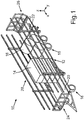
- a transport vehicle 10 is in a perspective view in FIG Fig. 1 shown.
- the loading platform 12 has a front loading platform part 20 mounted on a chassis 18 of the transport vehicle 10 and a rear loading platform part 22 which can be extended in the vehicle longitudinal direction x relative to the front loading platform part 20.
- a front end wall 24 At the front loading platform part 20 is a front end wall 24 and at the rear, extendable loading platform part 22 is a rear end wall 26 arranged for securing cargo.
- the loading platform 12 is also bounded laterally by two constructed in the form of lattice structures side walls 28.
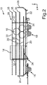
- Fig. 2 the transport vehicle 10 is shown in a side view.
- the lattice structure of one of the two side walls 28 is clearly visible.
- the side walls 28 are thus completely formed in the form of respective lattice structures, which have a plurality of horizontal struts 30 which are each hinged to two vertical struts 32.
- Respective lower longitudinal ends 34 of the vertical struts 32 are pivotably mounted on the front loading platform part 20 about respective unspecified pivot axes extending in the vehicle transverse direction y.
- the side walls 28 which are completely constructed in the form of the lattice structures can thereby be pivoted between an unfolded load securing position shown here, in which the vertical struts 32 extend in the vertical direction z of the transport vehicle 10, and a folded-off loading position in which the horizontal struts 30 abut one another.
- the side walls 28 formed in the form of the lattice structures also have a plurality of extension struts 35, which are arranged on the horizontal struts 30 for extending the side walls 28 in the vehicle longitudinal direction x.
- the length of the side walls 28 can thereby be adapted to the positioning of the extendable rear loading platform part 22.
- the extension struts 35 may be arranged longitudinally displaceably relative to the horizontal struts 30.
- Fig. 3 the transport vehicle 10 is shown in a further side view, wherein the two side walls 28 are shown in their folded-off loading position. A section A of the transport vehicle 10 is marked.
- Fig. 4 the detail A is shown in an enlarged detail view.
- the horizontal struts 32 in the vertical direction z abut each other when the side walls 28 have been brought into their folded-down loading position.
- respective hydraulic lifting cylinders 36 are provided on the transport vehicle 10 per side wall 28, by the actuation of which the side walls 28 are pivoted up and down can.
- the side walls 28 are preferably secured to the loading platform 12 and arranged such that the uppermost of the horizontal struts 30 in the folded-down loading position in the vehicle vertical direction z is either flush with a loading platform upper side or even below the loading platform upper side.
- the transport vehicle 10 can be loaded in a particularly simple manner from the side, if at least one of the side walls 28 is arranged in the folded-off loading position.
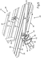
- a section of the transport vehicle 10 is shown in a perspective detail view, wherein one of the two side walls 28 is shown once in the folded-off loading position and with dashed lines in the unfolded load securing position.
- the transport vehicle 10 has an unspecified adjusting device, by means of which the side walls 28 designed as lattice structures are movable relative to the loading platform 12 in the vehicle transverse direction y.
- the adjusting device has a positive guide 38, by means of which the side walls 28 are moved away from the loading platform 12 when folded into the load securing position in the vehicle transverse direction y to the loading platform 12 and when folding down into the loading position.
- the forced guides 38 each have in the vehicle transverse direction y from an outside end portion 40 to an inside end portion 42 extending links 44, by means of which respective arranged on the longitudinal ends 34 of the vertical struts 32 guide elements 46 are positively driven in the unfolded load securing position on in each case inside end region 42 and in the folded-off loading position on the respective outer end region 40 of the links 44 are arranged.
- the guide elements 46 move in their respective scenes 44 in the vehicle transverse direction y to the outside, so that the side walls 28 in the vehicle transverse direction y move away from the loading platform 28.
- the guide elements 42 move forcibly in their respective scenes 44 in the vehicle transverse direction y inwards, so that the side walls 28 to move in the vehicle transverse direction y on the loading platform 28.
- the pivoting movement of the side walls 28 is coupled to a movement of the side walls 28 in the vehicle transverse direction y by the slide-like positive guides 38.
- a bottom side of the transport vehicle 10 is shown in a plan view, wherein the two side walls 28 are arranged in their folded down loading position. As can be seen, the two side walls 28 in the folded-down loading position in the vehicle transverse direction y are spaced from the loading platform 12.
- two of the positive guides 38 are also clearly visible, which are arranged in the region of the lower longitudinal ends 34. Each of the vertical struts 32 is thus guided by means of one of the positive guides 38, whereby the already explained motion coupling is achieved.
- a detailed view B of one of the forced guides 38 is also still in Fig. 6 shown.
- Fig. 7 the transport vehicle 10 is again shown in a plan view from below, wherein the side walls 28 are arranged in the present illustration in its upwardly pivoted load securing position.
- the two side walls 28 abut laterally on the loading platform 12 in their upwardly pivoted cargo securing position.
- the detail B is in Fig. 7 again shown in an enlarged view.
- the guide elements 46 which are positively guided within the respective slotted links 44, are located on the inside end region 42 when the side walls 28 have been pivoted upwards into the load securing position.
- the respective guide elements 46 in the respective scenes 44 migrate from the inside end region 42 to the outside end region 40, when the side walls 28 are pivoted from their folded up cargo securing position into the loading position folded downwards.
- the said adjustment of the transport vehicle 10 may alternatively or additionally, for example, a hydraulic adjustment mechanism, by means of which formed as a grid structures side walls 28 in the vehicle transverse direction y can be moved relative to the loading platform 12.
- a hydraulic adjustment mechanism by means of which formed as a grid structures side walls 28 in the vehicle transverse direction y can be moved relative to the loading platform 12.
- the hydraulic adjustment mechanism, the telescopic tubes in combination with the locking means and the positive guides 38 can also be combined with each other arbitrarily. Due to the adjustability of the side walls 28 in the vehicle transverse direction y relative to the loading platform 12, a load securing can be accomplished in a simple manner. Once the transport vehicle 10 has been loaded with the bale 14, 16 finished, the side walls 28 are folded upwards, whereby the bales 14, 16 are clamped between the two side walls 28.
- 16 can be carried out on the said hydraulic adjustment mechanism and / or the telescopic tubes, an additional adjustment of the side walls 28 in the vehicle transverse direction y, if necessary, the clamping of the bales 14, 16 between the side walls 28 in addition to increase.
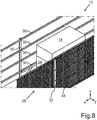
- Fig. 8 the transport vehicle 10 is shown in a perspective detail view, wherein at one of the two lattice-shaped side walls 28, a network structure 48 is attached.
- the network structure 48 may be, for example, a network or else a lattice-like structure of a plurality of belts.
- the net structure 48 is arranged in the vehicle transverse direction y between the horizontal struts 30 and the vertical struts 32 of the side wall 28 and preferably extends at least substantially along the entire side wall 28.
- the network structure 48 When unfolding the side wall 28 in the established load securing position, the network structure 48 is clamped, creating an additional Load securing function is provided by the network structure 48.
- the network structure 48 When folding down the side wall 28 in the lowered loading position, the network structure 48 is folded or folded so that it is not in the way of lateral loading of the transport vehicle 10 in the way.
- such network structures 48 can also be attached to both side walls 28, whereby a further improved load securing can be achieved. If, for example, individual parts of the bales 14, 16 come loose, they are prevented by the network structures 28 from falling from the transport vehicle. Furthermore, by attaching the net structures 28 on both sides, an even better clamping of the received bales 14, 16 in the vehicle transverse direction y can take place since the bales 14, 16 are clamped flatly between the network structures 48 attached to the side walls 28 when the side walls 28 are folded upwards Load securing position have been pivoted.
Landscapes
- Engineering & Computer Science (AREA)
- Transportation (AREA)
- Mechanical Engineering (AREA)
- Chemical & Material Sciences (AREA)
- Combustion & Propulsion (AREA)
- Life Sciences & Earth Sciences (AREA)
- Environmental Sciences (AREA)
- Health & Medical Sciences (AREA)
- Public Health (AREA)
- Body Structure For Vehicles (AREA)
- Loading Or Unloading Of Vehicles (AREA)
Claims (10)
- Véhicule de transport (10) pour marchandises diverses, en particulier pour des ballots (14, 16), avec une plate-forme de chargement (12), sur laquelle sont agencées latéralement une paroi latérale gauche (28) et une paroi latérale droite (28),
caractérisé en ce
qu'au moins l'une des parois latérales (28) est constituée intégralement sous forme d'une structure de grille, laquelle présente plusieurs barres horizontales (30), qui sont fixées, articulées, à au moins deux barres verticales (32), dont les extrémités longitudinales inférieures (34) sont logées de façon pivotante sur la plate-forme de chargement (12), autour d'axes de pivotement respectifs, évoluant dans le sens transversal (y) du véhicule, de sorte que la structure de grille peut pivoter entre une position déployée d'arrimage du chargement, dans laquelle les barres verticales (32) évoluent dans le sens ascendant (z) du véhicule de transport (10), et une position rabattue de chargement, dans laquelle les barres horizontales (30) sont en contact entre elles. - Véhicule de transport (10) selon la revendication 1,
caractérisé en ce que
la plus haute des barres horizontales (30) se termine, dans la position rabattue de chargement, dans le sens ascendant (z) du véhicule, de niveau avec une partie supérieure de la plate-forme de chargement ou est agencée au-dessous de la face supérieure de la plate-forme de chargement. - Véhicule de transport (10) selon la revendication 1 ou 2,
caractérisé en ce que
le véhicule de transport (10) présente un dispositif de déplacement, au moyen duquel la structure de grille peut être déplacée, dans le sens transversal (y) du véhicule, par rapport à la plate-forme de chargement (12). - Véhicule de transport (10) selon la revendication 3,
caractérisé en ce que
le dispositif de déplacement présente un guidage forcé (38), au moyen duquel la structure de grille est déplacée, lors du déploiement dans la position d'arrimage du chargement, dans le sens transversal (y) du véhicule, vers la plate-forme de chargement (12) et, lors du rabattement dans la position de chargement, s'éloigne de la plate-forme de chargement (12). - Véhicule de transport (10) selon la revendication 4,
caractérisé en ce que
le guidage forcé (38) présente des coulisseaux (44) respectifs, s'étendant, dans le sens transversal (y) du véhicule, depuis une zone d'extrémité, côté extérieur (40), vers une zone d'extrémité, côté intérieur (42), au moyen desquels sont guidés en force des éléments de guidage (46) respectifs, agencés sur les extrémités longitudinales (34) des barres verticales (32), éléments de guidage (46) qui sont agencés, dans la position d'arrimage de chargement déployée, respectivement, sur la zone d'extrémité, côté intérieur, (42) et, dans la position de chargement rabattue, respectivement, sur la zone d'extrémité, côté extérieur, (40) des coulisseaux (44). - Véhicule de transport (10) selon l'une des revendications 3 à 5,
caractérisé en ce que
le dispositif de déplacement présente un mécanisme de réglage hydraulique, au moyen duquel la structure de grille peut être déplacée dans le sens transversal (y) du véhicule, par rapport à la plate-forme de chargement (12). - Véhicule de transport (10) selon l'une des revendications 3 à 6,
caractérisé en ce que
le dispositif de déplacement présente au moins un tube télescopique, au moyen duquel la structure de grille est mobile, dans le sens transversal (y) du véhicule, par rapport à la plate-forme de chargement (12), le dispositif de déplacement comprenant au moins un moyen d'arrêt, en particulier un boulon enfichable, pour arrêter le tube télescopique. - Véhicule de transport (10) selon l'une des revendications précédentes,
caractérisé en ce que
la plate-forme de chargement (12) comprend une partie avant (20) de la plate-forme de chargement, fixée sur un châssis (18) du véhicule de transport (10), sur laquelle sont logées les extrémités longitudinales inférieures (34) des barres verticales (32), et une partie arrière (22) de la plate-forme de chargement, extensible par rapport à la partie avant (20) de la plate-forme de chargement, dans le sens longitudinal (x) du véhicule. - Véhicule de transport (10) selon l'une des revendications précédentes,
caractérisé en ce que
la structure de grille présente plusieurs barres de prolongement (35), lesquelles peuvent être agencées sur les barres horizontales (30), pour prolonger la structure de grille dans le sens longitudinal (x) du véhicule. - Véhicule de transport (10) selon la revendication 9,
caractérisé en ce que
les barres de prolongement (35) peuvent être agencées par rapport aux barres horizontales (30), en étant coulissantes dans le sens longitudinal sur celles-ci.
Priority Applications (1)
| Application Number | Priority Date | Filing Date | Title |
|---|---|---|---|
| PL16199147T PL3173286T3 (pl) | 2015-11-18 | 2016-11-16 | Pojazd transportowy dla drobnicy |
Applications Claiming Priority (1)
| Application Number | Priority Date | Filing Date | Title |
|---|---|---|---|
| DE202015106266.4U DE202015106266U1 (de) | 2015-11-18 | 2015-11-18 | Transportfahrzeug für Stückgut |
Publications (2)
| Publication Number | Publication Date |
|---|---|
| EP3173286A1 EP3173286A1 (fr) | 2017-05-31 |
| EP3173286B1 true EP3173286B1 (fr) | 2018-09-26 |
Family
ID=55274349
Family Applications (1)
| Application Number | Title | Priority Date | Filing Date |
|---|---|---|---|
| EP16199147.6A Active EP3173286B1 (fr) | 2015-11-18 | 2016-11-16 | Véhicule de transport pour matériaux en vrac |
Country Status (5)
| Country | Link |
|---|---|
| EP (1) | EP3173286B1 (fr) |
| DE (1) | DE202015106266U1 (fr) |
| HU (1) | HUE042441T2 (fr) |
| PL (1) | PL3173286T3 (fr) |
| RU (1) | RU2708873C2 (fr) |
Cited By (2)
| Publication number | Priority date | Publication date | Assignee | Title |
|---|---|---|---|---|
| EP4305952A1 (fr) * | 2022-07-14 | 2024-01-17 | Pöttinger Landtechnik GmbH | Remorque agricole |
| FR3139519A1 (fr) | 2022-09-13 | 2024-03-15 | Sarl Ponge Pere Et Fils | Dispositif d’arrimage de charges, notamment de balles de fourrage, sur un véhicule de transport de charges, et véhicule de transport de charges comprenant au moins un tel dispositif d’arrimage |
Families Citing this family (1)
| Publication number | Priority date | Publication date | Assignee | Title |
|---|---|---|---|---|
| FR3081284B1 (fr) * | 2018-05-28 | 2020-08-14 | Soc Ind D'applications Mecaniques | Plateau fourrager |
Family Cites Families (10)
| Publication number | Priority date | Publication date | Assignee | Title |
|---|---|---|---|---|
| AT266617B (de) * | 1966-11-23 | 1968-11-25 | Niederoesterr Molkerei | Faltbare Bordwand für Lastwagen, insbesondere Lastkraftwagen od.dgl. |
| SU417335A1 (fr) * | 1971-02-16 | 1974-02-28 | ||
| DE2538079C2 (de) * | 1975-08-27 | 1983-02-24 | Maschinenfabrik Fahr Ag Gottmadingen, 7702 Gottmadingen | Landwirtschaftliches Fahrzeug wie Lade-, Ernte-, Häckselwagen oder dergleichen |
| DE2901597C2 (de) * | 1979-01-17 | 1985-05-15 | Maschinenfabriken Bernard Krone Gmbh, 4441 Spelle | Landwirtschaftlicher Erntewagen mit einem den Laderaum bildenden zweiteiligen Wagenaufbau |
| SU1214509A1 (ru) * | 1983-05-04 | 1986-02-28 | Lukyanchuk Dmitrij V | Транспортное средство дл перевозки объемных сельскохоз йственных грузов |
| DE4005429A1 (de) | 1989-04-21 | 1990-10-25 | Poettinger Alois Landmasch | Landwirtschaftliche erntemaschine, insbesondere selbstladewagen mit einer hydraulischen steuervorrichtung |
| DE4223951A1 (de) * | 1992-07-21 | 1994-01-27 | Peter Dr Ing Boese | Stützeinrichtung für Wechselbehälter |
| RU2067059C1 (ru) * | 1996-04-08 | 1996-09-27 | Юрий Петрович Милай | Трансформируемый кузов пим транспортного средства |
| RU2314672C2 (ru) * | 2006-03-02 | 2008-01-20 | Федеральное государственное образовательное учреждение высшего профессионального образования "Ярославская государственная сельскохозяйственная академия" | Транспортное средство для погрузки, перевозки и разгрузки рулонов сенажа и сена |
| RU125939U1 (ru) * | 2012-10-01 | 2013-03-20 | Открытое акционерное общество "Нефтекамский автозавод" | Полуприцеп для перевозки зерновых культур и других сыпучих грузов |
-
2015
- 2015-11-18 DE DE202015106266.4U patent/DE202015106266U1/de active Active
-
2016
- 2016-11-16 EP EP16199147.6A patent/EP3173286B1/fr active Active
- 2016-11-16 PL PL16199147T patent/PL3173286T3/pl unknown
- 2016-11-16 HU HUE16199147A patent/HUE042441T2/hu unknown
- 2016-11-17 RU RU2016145073A patent/RU2708873C2/ru active
Non-Patent Citations (1)
| Title |
|---|
| None * |
Cited By (3)
| Publication number | Priority date | Publication date | Assignee | Title |
|---|---|---|---|---|
| EP4305952A1 (fr) * | 2022-07-14 | 2024-01-17 | Pöttinger Landtechnik GmbH | Remorque agricole |
| FR3139519A1 (fr) | 2022-09-13 | 2024-03-15 | Sarl Ponge Pere Et Fils | Dispositif d’arrimage de charges, notamment de balles de fourrage, sur un véhicule de transport de charges, et véhicule de transport de charges comprenant au moins un tel dispositif d’arrimage |
| EP4339021A1 (fr) | 2022-09-13 | 2024-03-20 | Sarl Ponge Père et Fils | Dispositif d'arrimage de charges, notamment de balles de fourrage, sur un véhicule de transport de charges, et véhicule de transport de charges comprenant au moins un tel dispositif d arrimage |
Also Published As
| Publication number | Publication date |
|---|---|
| RU2708873C2 (ru) | 2019-12-11 |
| RU2016145073A3 (fr) | 2018-08-10 |
| DE202015106266U1 (de) | 2016-01-18 |
| PL3173286T3 (pl) | 2019-02-28 |
| HUE042441T2 (hu) | 2019-06-28 |
| EP3173286A1 (fr) | 2017-05-31 |
| RU2016145073A (ru) | 2018-05-21 |
Similar Documents
| Publication | Publication Date | Title |
|---|---|---|
| DE202018106492U1 (de) | Fahrzeug zum Transportieren eines langen Transportguts | |
| EP3620327B1 (fr) | Véhicule élévateur à crochet ainsi que contenant pour un véhicule élévateur à crochet | |
| EP3173286B1 (fr) | Véhicule de transport pour matériaux en vrac | |
| EP2810822B1 (fr) | Véhicule de transbordement | |
| DE2228764A1 (de) | Klappwand fur Mulden Hinterkipper Fahrzeug | |
| DE1481873A1 (de) | Lasthebevorrichtung | |
| EP2944490B1 (fr) | Véhicule de transport pour matériaux en vrac | |
| DE2705979C3 (de) | Lastwagen mit in seiner Längsrichtung verschiebbarem Ladebodenabschnitt | |
| DE202010001105U1 (de) | Mobile Überladestation zum Überladen von Schüttgut | |
| EP2676824A2 (fr) | Structure pour le transports de biens | |
| DE102010003932A1 (de) | Verdeckvorrichtung für einen Lastentransportbehälter | |
| DE102005042243B4 (de) | Klappbarer Transportcontainer | |
| EP1616778A2 (fr) | Véhicule pour le transport de marchandises larges | |
| DE7718760U1 (de) | Vorrichtung zur Bewegung eines Containers auf dem Chassis eines Fahrzeuges | |
| DE2319652A1 (de) | Einrichtung zum be- und entladen eines containers bei einem sattelanhaenger | |
| DE1075441B (de) | Sattelschlepperanhänger mit selbsttätiger Kupplungsvorrichtung | |
| DE3812489C1 (en) | Lorry having stakes | |
| DE102013101966B4 (de) | Anordnung zum hydraulischen Stabilisieren eines Klappelements | |
| EP3275710B1 (fr) | Articulation a coulisseau | |
| DE2745751A1 (de) | Plattform, insbesondere fuer ladebordwaende bei kraftfahrzeugen o.dgl. | |
| WO2016042147A1 (fr) | Camion pourvu d'un dispositif de levage de conteneurs | |
| EP3000687B1 (fr) | Berceau de couverture pour un montage de superstructure d'un vehicule de transport | |
| EP2684781B1 (fr) | Structure pour le transports de biens | |
| DE202021003877U1 (de) | Ladungssicherungsvorrichtung für landwirtschaftliche Transportwagen | |
| DE2255609A1 (de) | Ladehilfsvorrichtung fuer lastfahrzeuge |
Legal Events
| Date | Code | Title | Description |
|---|---|---|---|
| PUAI | Public reference made under article 153(3) epc to a published international application that has entered the european phase |
Free format text: ORIGINAL CODE: 0009012 |
|
| AK | Designated contracting states |
Kind code of ref document: A1 Designated state(s): AL AT BE BG CH CY CZ DE DK EE ES FI FR GB GR HR HU IE IS IT LI LT LU LV MC MK MT NL NO PL PT RO RS SE SI SK SM TR |
|
| AX | Request for extension of the european patent |
Extension state: BA ME |
|
| 17P | Request for examination filed |
Effective date: 20171130 |
|
| RBV | Designated contracting states (corrected) |
Designated state(s): AL AT BE BG CH CY CZ DE DK EE ES FI FR GB GR HR HU IE IS IT LI LT LU LV MC MK MT NL NO PL PT RO RS SE SI SK SM TR |
|
| GRAP | Despatch of communication of intention to grant a patent |
Free format text: ORIGINAL CODE: EPIDOSNIGR1 |
|
| INTG | Intention to grant announced |
Effective date: 20180425 |
|
| GRAS | Grant fee paid |
Free format text: ORIGINAL CODE: EPIDOSNIGR3 |
|
| GRAA | (expected) grant |
Free format text: ORIGINAL CODE: 0009210 |
|
| AK | Designated contracting states |
Kind code of ref document: B1 Designated state(s): AL AT BE BG CH CY CZ DE DK EE ES FI FR GB GR HR HU IE IS IT LI LT LU LV MC MK MT NL NO PL PT RO RS SE SI SK SM TR |
|
| REG | Reference to a national code |
Ref country code: GB Ref legal event code: FG4D Free format text: NOT ENGLISH |
|
| REG | Reference to a national code |
Ref country code: CH Ref legal event code: EP |
|
| REG | Reference to a national code |
Ref country code: AT Ref legal event code: REF Ref document number: 1045599 Country of ref document: AT Kind code of ref document: T Effective date: 20181015 |
|
| REG | Reference to a national code |
Ref country code: IE Ref legal event code: FG4D Free format text: LANGUAGE OF EP DOCUMENT: GERMAN |
|
| REG | Reference to a national code |
Ref country code: DE Ref legal event code: R096 Ref document number: 502016002088 Country of ref document: DE |
|
| REG | Reference to a national code |
Ref country code: CH Ref legal event code: NV Representative=s name: VALIPAT S.A. GEVERS SA, CH |
|
| REG | Reference to a national code |
Ref country code: NL Ref legal event code: MP Effective date: 20180926 |
|
| PG25 | Lapsed in a contracting state [announced via postgrant information from national office to epo] |
Ref country code: NO Free format text: LAPSE BECAUSE OF FAILURE TO SUBMIT A TRANSLATION OF THE DESCRIPTION OR TO PAY THE FEE WITHIN THE PRESCRIBED TIME-LIMIT Effective date: 20181226 Ref country code: RS Free format text: LAPSE BECAUSE OF FAILURE TO SUBMIT A TRANSLATION OF THE DESCRIPTION OR TO PAY THE FEE WITHIN THE PRESCRIBED TIME-LIMIT Effective date: 20180926 Ref country code: FI Free format text: LAPSE BECAUSE OF FAILURE TO SUBMIT A TRANSLATION OF THE DESCRIPTION OR TO PAY THE FEE WITHIN THE PRESCRIBED TIME-LIMIT Effective date: 20180926 Ref country code: GR Free format text: LAPSE BECAUSE OF FAILURE TO SUBMIT A TRANSLATION OF THE DESCRIPTION OR TO PAY THE FEE WITHIN THE PRESCRIBED TIME-LIMIT Effective date: 20181227 Ref country code: BG Free format text: LAPSE BECAUSE OF FAILURE TO SUBMIT A TRANSLATION OF THE DESCRIPTION OR TO PAY THE FEE WITHIN THE PRESCRIBED TIME-LIMIT Effective date: 20181226 Ref country code: LT Free format text: LAPSE BECAUSE OF FAILURE TO SUBMIT A TRANSLATION OF THE DESCRIPTION OR TO PAY THE FEE WITHIN THE PRESCRIBED TIME-LIMIT Effective date: 20180926 |
|
| REG | Reference to a national code |
Ref country code: LT Ref legal event code: MG4D |
|
| PG25 | Lapsed in a contracting state [announced via postgrant information from national office to epo] |
Ref country code: AL Free format text: LAPSE BECAUSE OF FAILURE TO SUBMIT A TRANSLATION OF THE DESCRIPTION OR TO PAY THE FEE WITHIN THE PRESCRIBED TIME-LIMIT Effective date: 20180926 Ref country code: LV Free format text: LAPSE BECAUSE OF FAILURE TO SUBMIT A TRANSLATION OF THE DESCRIPTION OR TO PAY THE FEE WITHIN THE PRESCRIBED TIME-LIMIT Effective date: 20180926 Ref country code: HR Free format text: LAPSE BECAUSE OF FAILURE TO SUBMIT A TRANSLATION OF THE DESCRIPTION OR TO PAY THE FEE WITHIN THE PRESCRIBED TIME-LIMIT Effective date: 20180926 |
|
| REG | Reference to a national code |
Ref country code: CH Ref legal event code: PCAR Free format text: NEW ADDRESS: RUE DES NOYERS 11, 2000 NEUCHATEL (CH) |
|
| PG25 | Lapsed in a contracting state [announced via postgrant information from national office to epo] |
Ref country code: NL Free format text: LAPSE BECAUSE OF FAILURE TO SUBMIT A TRANSLATION OF THE DESCRIPTION OR TO PAY THE FEE WITHIN THE PRESCRIBED TIME-LIMIT Effective date: 20180926 Ref country code: EE Free format text: LAPSE BECAUSE OF FAILURE TO SUBMIT A TRANSLATION OF THE DESCRIPTION OR TO PAY THE FEE WITHIN THE PRESCRIBED TIME-LIMIT Effective date: 20180926 Ref country code: ES Free format text: LAPSE BECAUSE OF FAILURE TO SUBMIT A TRANSLATION OF THE DESCRIPTION OR TO PAY THE FEE WITHIN THE PRESCRIBED TIME-LIMIT Effective date: 20180926 Ref country code: IS Free format text: LAPSE BECAUSE OF FAILURE TO SUBMIT A TRANSLATION OF THE DESCRIPTION OR TO PAY THE FEE WITHIN THE PRESCRIBED TIME-LIMIT Effective date: 20190126 Ref country code: CZ Free format text: LAPSE BECAUSE OF FAILURE TO SUBMIT A TRANSLATION OF THE DESCRIPTION OR TO PAY THE FEE WITHIN THE PRESCRIBED TIME-LIMIT Effective date: 20180926 Ref country code: RO Free format text: LAPSE BECAUSE OF FAILURE TO SUBMIT A TRANSLATION OF THE DESCRIPTION OR TO PAY THE FEE WITHIN THE PRESCRIBED TIME-LIMIT Effective date: 20180926 Ref country code: IT Free format text: LAPSE BECAUSE OF FAILURE TO SUBMIT A TRANSLATION OF THE DESCRIPTION OR TO PAY THE FEE WITHIN THE PRESCRIBED TIME-LIMIT Effective date: 20180926 |
|
| PG25 | Lapsed in a contracting state [announced via postgrant information from national office to epo] |
Ref country code: SM Free format text: LAPSE BECAUSE OF FAILURE TO SUBMIT A TRANSLATION OF THE DESCRIPTION OR TO PAY THE FEE WITHIN THE PRESCRIBED TIME-LIMIT Effective date: 20180926 Ref country code: PT Free format text: LAPSE BECAUSE OF FAILURE TO SUBMIT A TRANSLATION OF THE DESCRIPTION OR TO PAY THE FEE WITHIN THE PRESCRIBED TIME-LIMIT Effective date: 20190126 Ref country code: SK Free format text: LAPSE BECAUSE OF FAILURE TO SUBMIT A TRANSLATION OF THE DESCRIPTION OR TO PAY THE FEE WITHIN THE PRESCRIBED TIME-LIMIT Effective date: 20180926 |
|
| REG | Reference to a national code |
Ref country code: DE Ref legal event code: R082 Ref document number: 502016002088 Country of ref document: DE Representative=s name: NUSSBAUM, CHRISTOPHER, DIPL.-ING. DR.-ING., DE |
|
| REG | Reference to a national code |
Ref country code: DE Ref legal event code: R097 Ref document number: 502016002088 Country of ref document: DE |
|
| REG | Reference to a national code |
Ref country code: HU Ref legal event code: AG4A Ref document number: E042441 Country of ref document: HU |
|
| PG25 | Lapsed in a contracting state [announced via postgrant information from national office to epo] |
Ref country code: DK Free format text: LAPSE BECAUSE OF FAILURE TO SUBMIT A TRANSLATION OF THE DESCRIPTION OR TO PAY THE FEE WITHIN THE PRESCRIBED TIME-LIMIT Effective date: 20180926 Ref country code: MC Free format text: LAPSE BECAUSE OF FAILURE TO SUBMIT A TRANSLATION OF THE DESCRIPTION OR TO PAY THE FEE WITHIN THE PRESCRIBED TIME-LIMIT Effective date: 20180926 Ref country code: LU Free format text: LAPSE BECAUSE OF NON-PAYMENT OF DUE FEES Effective date: 20181116 |
|
| PLBE | No opposition filed within time limit |
Free format text: ORIGINAL CODE: 0009261 |
|
| STAA | Information on the status of an ep patent application or granted ep patent |
Free format text: STATUS: NO OPPOSITION FILED WITHIN TIME LIMIT |
|
| REG | Reference to a national code |
Ref country code: IE Ref legal event code: MM4A |
|
| 26N | No opposition filed |
Effective date: 20190627 |
|
| PG25 | Lapsed in a contracting state [announced via postgrant information from national office to epo] |
Ref country code: IE Free format text: LAPSE BECAUSE OF NON-PAYMENT OF DUE FEES Effective date: 20181116 Ref country code: SI Free format text: LAPSE BECAUSE OF FAILURE TO SUBMIT A TRANSLATION OF THE DESCRIPTION OR TO PAY THE FEE WITHIN THE PRESCRIBED TIME-LIMIT Effective date: 20180926 Ref country code: FR Free format text: LAPSE BECAUSE OF NON-PAYMENT OF DUE FEES Effective date: 20181126 |
|
| PG25 | Lapsed in a contracting state [announced via postgrant information from national office to epo] |
Ref country code: MT Free format text: LAPSE BECAUSE OF FAILURE TO SUBMIT A TRANSLATION OF THE DESCRIPTION OR TO PAY THE FEE WITHIN THE PRESCRIBED TIME-LIMIT Effective date: 20180926 |
|
| REG | Reference to a national code |
Ref country code: DE Ref legal event code: R082 Ref document number: 502016002088 Country of ref document: DE Representative=s name: NUSSBAUM, CHRISTOPHER, DIPL.-ING. DR.-ING., DE |
|
| PG25 | Lapsed in a contracting state [announced via postgrant information from national office to epo] |
Ref country code: TR Free format text: LAPSE BECAUSE OF FAILURE TO SUBMIT A TRANSLATION OF THE DESCRIPTION OR TO PAY THE FEE WITHIN THE PRESCRIBED TIME-LIMIT Effective date: 20180926 |
|
| PG25 | Lapsed in a contracting state [announced via postgrant information from national office to epo] |
Ref country code: CY Free format text: LAPSE BECAUSE OF FAILURE TO SUBMIT A TRANSLATION OF THE DESCRIPTION OR TO PAY THE FEE WITHIN THE PRESCRIBED TIME-LIMIT Effective date: 20180926 Ref country code: SE Free format text: LAPSE BECAUSE OF FAILURE TO SUBMIT A TRANSLATION OF THE DESCRIPTION OR TO PAY THE FEE WITHIN THE PRESCRIBED TIME-LIMIT Effective date: 20180926 Ref country code: MK Free format text: LAPSE BECAUSE OF NON-PAYMENT OF DUE FEES Effective date: 20180926 |
|
| PGFP | Annual fee paid to national office [announced via postgrant information from national office to epo] |
Ref country code: GB Payment date: 20231123 Year of fee payment: 8 |
|
| PGFP | Annual fee paid to national office [announced via postgrant information from national office to epo] |
Ref country code: HU Payment date: 20231113 Year of fee payment: 8 Ref country code: DE Payment date: 20231120 Year of fee payment: 8 Ref country code: CH Payment date: 20231201 Year of fee payment: 8 Ref country code: AT Payment date: 20231117 Year of fee payment: 8 |
|
| PGFP | Annual fee paid to national office [announced via postgrant information from national office to epo] |
Ref country code: PL Payment date: 20231103 Year of fee payment: 8 Ref country code: BE Payment date: 20231121 Year of fee payment: 8 |