EP3173060B1 - Cassette de médicament - Google Patents
Cassette de médicament Download PDFInfo
- Publication number
- EP3173060B1 EP3173060B1 EP15825431.8A EP15825431A EP3173060B1 EP 3173060 B1 EP3173060 B1 EP 3173060B1 EP 15825431 A EP15825431 A EP 15825431A EP 3173060 B1 EP3173060 B1 EP 3173060B1
- Authority
- EP
- European Patent Office
- Prior art keywords
- medicine
- rotator
- cassette
- rotation axis
- motor
- Prior art date
- Legal status (The legal status is an assumption and is not a legal conclusion. Google has not performed a legal analysis and makes no representation as to the accuracy of the status listed.)
- Active
Links
- 239000003814 drug Substances 0.000 title claims description 195
- 229940079593 drug Drugs 0.000 title description 60
- 230000002093 peripheral effect Effects 0.000 claims description 16
- 230000000717 retained effect Effects 0.000 claims description 4
- 230000000052 comparative effect Effects 0.000 description 12
- 239000003826 tablet Substances 0.000 description 12
- 238000010276 construction Methods 0.000 description 7
- 230000033001 locomotion Effects 0.000 description 6
- 238000004806 packaging method and process Methods 0.000 description 6
- 238000002474 experimental method Methods 0.000 description 4
- 230000001105 regulatory effect Effects 0.000 description 3
- 238000004891 communication Methods 0.000 description 2
- 230000005489 elastic deformation Effects 0.000 description 2
- 239000000463 material Substances 0.000 description 2
- 238000000034 method Methods 0.000 description 2
- 230000008569 process Effects 0.000 description 2
- 238000011144 upstream manufacturing Methods 0.000 description 2
- 238000005299 abrasion Methods 0.000 description 1
- 230000009471 action Effects 0.000 description 1
- 239000002775 capsule Substances 0.000 description 1
- 230000008859 change Effects 0.000 description 1
- LYKJEJVAXSGWAJ-UHFFFAOYSA-N compactone Natural products CC1(C)CCCC2(C)C1CC(=O)C3(O)CC(C)(CCC23)C=C LYKJEJVAXSGWAJ-UHFFFAOYSA-N 0.000 description 1
- 239000007947 dispensing tablet Substances 0.000 description 1
- 238000006073 displacement reaction Methods 0.000 description 1
- 230000000694 effects Effects 0.000 description 1
- 238000009472 formulation Methods 0.000 description 1
- 230000003116 impacting effect Effects 0.000 description 1
- 238000009434 installation Methods 0.000 description 1
- 239000011159 matrix material Substances 0.000 description 1
- 239000000203 mixture Substances 0.000 description 1
- 238000012986 modification Methods 0.000 description 1
- 230000004048 modification Effects 0.000 description 1
- 230000004044 response Effects 0.000 description 1
- 229920002379 silicone rubber Polymers 0.000 description 1
- 239000004945 silicone rubber Substances 0.000 description 1
- 239000007787 solid Substances 0.000 description 1
- 238000012546 transfer Methods 0.000 description 1
Images


Classifications
-
- A—HUMAN NECESSITIES
- A61—MEDICAL OR VETERINARY SCIENCE; HYGIENE
- A61J—CONTAINERS SPECIALLY ADAPTED FOR MEDICAL OR PHARMACEUTICAL PURPOSES; DEVICES OR METHODS SPECIALLY ADAPTED FOR BRINGING PHARMACEUTICAL PRODUCTS INTO PARTICULAR PHYSICAL OR ADMINISTERING FORMS; DEVICES FOR ADMINISTERING FOOD OR MEDICINES ORALLY; BABY COMFORTERS; DEVICES FOR RECEIVING SPITTLE
- A61J3/00—Devices or methods specially adapted for bringing pharmaceutical products into particular physical or administering forms
-
- A—HUMAN NECESSITIES
- A61—MEDICAL OR VETERINARY SCIENCE; HYGIENE
- A61J—CONTAINERS SPECIALLY ADAPTED FOR MEDICAL OR PHARMACEUTICAL PURPOSES; DEVICES OR METHODS SPECIALLY ADAPTED FOR BRINGING PHARMACEUTICAL PRODUCTS INTO PARTICULAR PHYSICAL OR ADMINISTERING FORMS; DEVICES FOR ADMINISTERING FOOD OR MEDICINES ORALLY; BABY COMFORTERS; DEVICES FOR RECEIVING SPITTLE
- A61J7/00—Devices for administering medicines orally, e.g. spoons; Pill counting devices; Arrangements for time indication or reminder for taking medicine
- A61J7/0076—Medicament distribution means
-
- B—PERFORMING OPERATIONS; TRANSPORTING
- B65—CONVEYING; PACKING; STORING; HANDLING THIN OR FILAMENTARY MATERIAL
- B65B—MACHINES, APPARATUS OR DEVICES FOR, OR METHODS OF, PACKAGING ARTICLES OR MATERIALS; UNPACKING
- B65B1/00—Packaging fluent solid material, e.g. powders, granular or loose fibrous material, loose masses of small articles, in individual containers or receptacles, e.g. bags, sacks, boxes, cartons, cans, or jars
- B65B1/30—Devices or methods for controlling or determining the quantity or quality or the material fed or filled
-
- B—PERFORMING OPERATIONS; TRANSPORTING
- B65—CONVEYING; PACKING; STORING; HANDLING THIN OR FILAMENTARY MATERIAL
- B65B—MACHINES, APPARATUS OR DEVICES FOR, OR METHODS OF, PACKAGING ARTICLES OR MATERIALS; UNPACKING
- B65B37/00—Supplying or feeding fluent-solid, plastic, or liquid material, or loose masses of small articles, to be packaged
- B65B37/08—Supplying or feeding fluent-solid, plastic, or liquid material, or loose masses of small articles, to be packaged by rotary feeders
-
- B—PERFORMING OPERATIONS; TRANSPORTING
- B65—CONVEYING; PACKING; STORING; HANDLING THIN OR FILAMENTARY MATERIAL
- B65D—CONTAINERS FOR STORAGE OR TRANSPORT OF ARTICLES OR MATERIALS, e.g. BAGS, BARRELS, BOTTLES, BOXES, CANS, CARTONS, CRATES, DRUMS, JARS, TANKS, HOPPERS, FORWARDING CONTAINERS; ACCESSORIES, CLOSURES, OR FITTINGS THEREFOR; PACKAGING ELEMENTS; PACKAGES
- B65D83/00—Containers or packages with special means for dispensing contents
- B65D83/04—Containers or packages with special means for dispensing contents for dispensing annular, disc-shaped, or spherical or like small articles, e.g. tablets or pills
- B65D83/0409—Containers or packages with special means for dispensing contents for dispensing annular, disc-shaped, or spherical or like small articles, e.g. tablets or pills the dispensing means being adapted for delivering one article, or a single dose, upon each actuation
-
- B—PERFORMING OPERATIONS; TRANSPORTING
- B65—CONVEYING; PACKING; STORING; HANDLING THIN OR FILAMENTARY MATERIAL
- B65G—TRANSPORT OR STORAGE DEVICES, e.g. CONVEYORS FOR LOADING OR TIPPING, SHOP CONVEYOR SYSTEMS OR PNEUMATIC TUBE CONVEYORS
- B65G29/00—Rotary conveyors, e.g. rotating discs, arms, star-wheels or cones
-
- B—PERFORMING OPERATIONS; TRANSPORTING
- B65—CONVEYING; PACKING; STORING; HANDLING THIN OR FILAMENTARY MATERIAL
- B65G—TRANSPORT OR STORAGE DEVICES, e.g. CONVEYORS FOR LOADING OR TIPPING, SHOP CONVEYOR SYSTEMS OR PNEUMATIC TUBE CONVEYORS
- B65G2201/00—Indexing codes relating to handling devices, e.g. conveyors, characterised by the type of product or load being conveyed or handled
- B65G2201/02—Articles
- B65G2201/027—Tablets, capsules, pills or the like
Definitions
- the present invention relates to a medicine cassette.
- WO 2013/035692 discloses a medicine supply device comprising a tube-shaped body housing a first rotating body to form together a medicine containing section capable of containing a medicine.
- the first rotating body can reciprocate in the axial direction of the tube-shaped body and is rotatable about a first rotation axis.
- the device comprises also a second rotating body disposed at the outer periphery of the opening of the tube-shaped body and rotatable about a second rotation axis. Owing to such configuration the device can contain a large amount of medicine, while being capable of smoothly and automatically dispensing the medicine.
- the present invention may provide a medicine cassette comprising a medicine dispensing unit for dispensing a medicine retained, the medicine dispensing unit may comprise a first rotator having a circular face rotatably disposed at a slant state to a horizontal plane; a second rotator having a ring face rotatably disposed over the horizontal plane at an outer peripheral side of the first rotator; and a guide member having a guide face, the guide face being disposed above the circular face of the first rotator while extending radially with respect to the circular face, being positioned at a downstream side in a rotational direction of the first rotator towards a periphery in a radial direction, and being capable of contacting to the medicine placed on the first rotator due to rotation of the first rotator.
- the medicine moves toward a circumference direction according to the rotation thereof to contact with the guide face of the guide member and then moves to a radially outer side along the guide face. Therefore, even though the first rotator is not rotated at high speeds, the medicine may be moved smoothly to the radially outer side by the guide member.
- At least a part including the guide face to be contacted to the medicine is capable of deforming elastically so as to modify a positional relationship to the second rotator depending on a size of the medicine.
- the first rotator is rotated at a rate at which the medicine is not allowed to move to an outer peripheral side only by a centrifugal force, but is allowed to move to the outer peripheral side along the guide member.
- first rotator and the second rotator are rotated by an identical driver means.
- the construction may be simplified and a compact one. This may be arisen from the fact that there is no need for increasing a rotation speed of the first rotator by disposing the guide member of the above feature. Besides, since a rotation speed of the second rotator may be suppressed so that dispensing accuracy for dispensing certainly the medicine one by one may be improved.
- first rotator and the second rotator are stopped every time one medicine is dispensed.
- the medicine may be dispensed certainly one by one.
- this feature may be effective when the first rotator and the second rotator are rotated by an identical driver means.
- a medicine supplying unit for supplying the medicine to the medicine dispensing unit is disposed and that the medicine supplying unit is capable of supplying the medicine depending on replenishment status of the medicine at the medicine dispensing unit.
- amounts of medicines at the medicine dispensing unit may be always controlled to values suitable for dispensing action.
- the medicine supplying unit is detachable from the medicine dispensing unit and comprises a supply port for supplying the medicine to the medicine dispensing unit and a shutter member for closing the supply port when the medicine dispensing unit is detached from the medicine supplying unit.
- the supply port may be closed by the shutter member so that falling down of the medicines may be protected as for safe handling when the medicines stay in the medicine supplying unit.
- the medicine cassette is attachable to and detachable from a cassette attaching part, and the shutter member closes the supply port of the medicine dispensing unit when the medicine cassette is detached from the cassette attaching part.
- the medicine cassette when there are necessities for supplying the medicines, the medicine cassette may be detached from the cassette attaching part and since the supply port is closed by the shutter member so that there may be no care about spilling out of the medicines even though the medicines remain in the medicine supply unit.
- the medicines since the guide member is provided, the medicines may be moved smoothly to the second rotator if a rotation speed of the first rotator is not fast.
- the medicines may be dispensed certainly one by one.
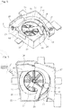
- the medicine cassette 5 comprises, as shown in Fig. 2 , a medicine reserving unit 6 and a medicine dispensing unit 7.
- the medicine reserving unit 6 is constructed by disposing a supplying rotator 9 in a reserving container 8.
- a plurality of medicines 10 of the same kind e.g. tablet or capsule
- the reserving container 8 as shown in Fig. 3 , comprises a surrounding wall 11 which has an almost trapezoid shape in a top view.
- a guide wall 12 extending downwardly and slantingly is formed on one inner face of a side wall which constructs the surrounding wall 11.
- the medicines 10 may be supplied using this guide wall 12.
- the guide wall 12 allows the supplied medicines 10 to move smoothly toward a bottom plane side and prevents the medicines 10 from being damaged by impacting the bottom plane side strongly.
- a supply port 13 is formed at a lower side below a region to which the guide wall 12 is formed.
- the supply port 13 may be capable of being opened and closed by a shutter 14 which constructs a shutter member of the present invention.
- the shutter 14 may preferably be configured to automatically close when the medicine cassette 5 is detached from the cassette attaching part.
- the supply port 13 may be closed by the shutter 14 biased by a springs etc. and a contact portion is disposed to the cassette attaching part such that a part of the shutter 14 may contact to the contact portion so as to open the supply port 13.
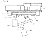
- the supplying rotator 9 has a circular shape and comprises an outer peripheral gear 17 as shown in Fig. 4 .
- a plurality of ridges 18 extend radially outwardly from a rotation center on an upper face.
- the outer peripheral gear 17 meshes with a first gear 19 and a second gear 20 sequentially and the second gear 20 is integrated to a rotation axis of a first motor 21.
- driving force of the first motor 21 may be transferred to the supplying rotator 9 through the second gear 20 and the first gear 19.
- the first motor 21 may be capable of rotating positively and negatively.
- the ridges 18 extend outwardly and evenly from the rotation axis to a radially outward peripheral side, and in detailed description extend curvedly with gradual displacements toward an upstream side in a rotational direction.
- the supporting container 22 is constructed with a surrounding side wall and a bottom wall and each of the supporting member 23, the height regulation member 26 and the width regulation member 27 may be fixed by screwing thereto.
- a discharge port 29 for the medicines 10 is formed.
- the medicines 10 discharged from the discharge port 29, as shown in Fig. 3 may be countably detected by a sensor 30.
- a rectangular protrusion part 31 with a slant top face is formed at the bottom wall and a cylinder part 32 is formed at a center thereof for rotatably supporting the first rotator 24.
- an arch part 33 protrudes in the condition in which a part of a cylinder shape about a center axis of the cylinder part 32 is cut off.
- An inner face of the arch part 33 and the slant upper face of the first rotator 24 construct a reserving concave part 34 (see Fig. 5 ).
- a ring part 35 is formed around the arch part 33.
- the second rotator 25 is mounted.
- Driving force of a third motor 45 may be transferred to the second rotator part 25 from a driving gear 46 which is mentioned below through a communication opening 36 formed by cutting off a part of the reserving concave part 34.
- the supporting member 23 is disposed in the concave of the supporting container 22 and is fixed by screwing from a lower face side.
- a part of the supporting member 23 is constructed with a protrusion part 37.
- An inner face of the protrusion part 37 constructs a part of an inner face surrounding an outer peripheral part of the second rotator 25.
- the guide member 28 may be fixed by screwing on an upper face of the protrusion part 37.
- a following gear 40 is integrated.
- a driving gear 42 which is integrated to a rotation axis of the second motor 41, meshes with the following gear 40. Thereby, the driving force of the second motor 41 may be transferred to the first rotator 24 through the driving gear 42 and the following gear 40.
- the second rotator 25 is, as shown in Fig. 7 , a planar ring plate which is disposed at the outer periphery of the first rotator 24.
- the second rotator 25 is disposed such that the upper face i.e. the ring face, is disposed so as to be positioned over a horizontal face.
- the cylinder part 43 is formed at a lower face side of the second rotator 25 and a following gear 44 is formed at an outer peripheral face thereof.
- a driving gear 46 as shown in Fig. 8 , which is integrated to a rotation axis of the third motor 45, meshes with the following gear 44. Thereby, the driving force of the third motor 45 may be transferred to the second rotator 25 through the driving gear 46 and the following gear 44.
- the height regulation member 26 is shaped generally to a rectangular solid and provides a space between a bottom face thereof and the second rotator 25 when fixed by screwing to a side wall of the supporting container 22.
- the space may be adjusted by changing a screwing position for fixing so as to allow only one medicine 10 to pass through.
- the width regulation member 27 comprises a curved surface 47.
- the width regulation member 27 is fixed by screwing to the side wall of the supporting container 22 and is disposed so as to extend inwardly beyond the outer periphery of the second rotator 25 for regulating an exposed width size of an upper face of the second rotator 25 so that only one medicine 10 may be carried by the second rotator 25.
- the exposed width size may be adjusted by changing a screwing position for fixing.
- the guide member 28 is constructed by a support member 48 and a guide chip 49.
- the support member 48 is formed to about an "L" letter shape from a planar plate and a through hole for fixing to the support member 23 by screwing is formed at one end side.
- the strip shaped guide chip 49 is fixed at a right angled direction against the upper face of the first rotator 24 in the condition out of contact.
- a material having flexibility as well as an excellent anti-abrasion property such as a silicone rubber may be used.
- the guide chip 49 curves gradually to a downstream side of the rotational direction of the first rotator 24 against a radial direction to which the opposite end of the supporting member 48 extends (in Fig. 6 , shown by two dotted line). Thereby, the guide face, which swells out to the outer radial side of the first rotator 24, may be formed.
- the medicine 10 may be moved to an outer radial side by an elastic deformation thereof.
- a tip position of the guide chip 49 reaches adjacent to an inner peripheral edge of the second rotator 25 and is located at a shifted position toward the rotational direction from the position where a stepwise difference between the upper face of the first rotator 24 and the upper face of the second rotator 25 becomes almost zero (in Fig. 6 , though a pressured contacting state of the medicine 10 to the guide chip 49 is not illustrated, the guide chip 49 will be curved by the pressurized contact of the medicine 10.). Since the tip position of the guide chip 49 is set as described above, the guide chip 49 does not hinder the rotational movement of the second rotator 25 and the medicine 10 can certainly be moved onto the second rotator 25 from the first rotator 24.
- the tip of the guide chip 49 of the guide member 28 is located at the position where the tip is rotated at about 40 degrees - about 45 degrees from a referenced position at which the stepwise difference between the slant first rotator 24 and the second rotator 25 becomes zero.
- the height regulation member 26 is disposed at about 90 degrees rotated position from the referenced position such that the height size of the medicine 10 may be regulated.
- the width regulation member 27 is positioned at about 180 degrees rotated position from the referenced position.
- the controller unit 4 executes motion control for the first motor 21, the second motor 41, and the third motor 45 on the basis of sensor signals of the sensor 30 as well as formulation data from a server (not shown) to carry out the dispensing process as described hereunder.
- the centrifugal force exerted to the medicine 10 becomes insufficient.
- the rotation speed of the first rotator 24 becomes high, slipping contact speeds between the medicines 10 and the first rotator 24 become increased and conditions in which the medicines 10 are easy to be damaged are created.
- the rotation speed of the fist rotator 24 may be lowered than the conventional one so that the medicines 10 may be transferred onto the second rotator 25 certainly while reducing the damage of the medicines 10 sufficiently.
- the rotation speed of the first rotator 24 is set to be the same with that of the second rotator 25. That is to say, the speed may be adjusted suitable for dispensing the medicines 10 certainly one by one.
- the guide chip 49 is constructed using the material having elasticity. The positions of a height regulation body 26 and a width regulation body 27 are adjustable in response to sizes of the medicines as dispensing objects.
- medicines having various sizes may be dispensed.
- the medicines 10 as the dispensing objects have different characters in sizes, forms, and weights. Therefore, if the guide chip 49 is formed with a rigid body, it may be suspicious to blockages of the medicines 10 when the medicines 10 move along the guide chip 49. In this instance, since the guide chip 49 may change the deformation amounts depending on the difference of the characters, particularly in differences of the sizes of the medicines 10, a distance to the inner circumference face formed by the supporting member 23 may be changed to appropriate values. As the result, the guide chip 49 may recover the shape prior to the blockage of the medicines 10 so that the blockage state may be cleared or the blockage may not occur.
- the guide chip 49 may be deformed largely and recover the shape thereof when it bends beyond certain dimensions. As the result, the guide chip 49 may push back a plurality of medicines or depending on cases, the guide chip 49 flicks off the medicines toward the upstream side in the rotational direction of the first rotator 24.
- the blockage of the medicines becomes harder between the tip of the guide chip 49 and the inner circumference face of the supporting member 23 and it may be suppressed that a plurality of medicines pass through at the same time between the tip of the guide chip 49 and the inner circumference face of the supporting member 23.
- the medicines 10 after moved to the outer radial side are transferred to the second rotator 25 from the first rotator 24.
- the medicines 10 after passed through the height regulation member 26 but oversized beyond a predetermined width size (for example, medicines placed 2 lines side by side, and the like) are returned inwardly by the width regulation member 27.
- the only one medicine 10 after passing regulated allowable regions for passing through by the height regulation member 26 and the width regulation member 27 may be dispensed from the discharge port 29.
- the rotations of the first rotator 24 and the second rotator 25 are terminated. Thereby, one medicine 10 may be dispensed certainly. Then, the rotations of the first rotator 24 and the second rotator 25 will be restarted again. The termination and restart will be repeated each time one medicine 10 is detected by the sensor 30. The dispensing process will be terminated when predetermined numbers of the medicines 10 have been dispensed.
- a sensor detects whether the dispensed medicine 10 from the reserving concave part 34 of the medicine dispensing unit 7 is positioned at a particular position or not (for example, on the second rotator 25) and if determination that the medicine is not positioned at the particular position, the rotation of the supplying rotator 9 may be started. Furthermore, by detecting that the medicine is positioned on the particular position, the supplying rotator 9 may be terminated. Alternatively, when amounts of the medicines 10 to be dispensed run up to predetermined given amounts, the determination may be made that the supply of the medicines 10 is necessary and then the supplying rotator 9 may be rotated.
- the rotation of the supplying rotator 9 may be performed for predetermined time duration on the basis of relations between the time duration determined by experiments and the amounts of the medicines 10 allowed to be supplied.
- the medicines may be supplied on the basis of supply conditions of the medicines 10 in the medicine dispensing unit 7 (the former predicts whether the supply condition permits the dispensation or not depending on presence or absence of the medicines 10 at the particular position and the latter calculates the amounts of medicines 10 in the medicine dispensing unit 7 from practically dispensed amounts and specifies the supply condition precisely.).
- the outer diameter size of the first rotator 24 was set to be 40 mm and the slant angle of the first rotator 24 was set to be 13 degrees against the horizontal plane. Tablets having a diameter of 10 mm were dispensed under the conditions listed in Table 1.
- Table 1 Comparative Example 1 Comparative Example 2 Comparative Example 3
- the minimal rotation speeds of the first rotator 24 required for dispensing the tablets to the second rotator were to be 110 rpm in the comparative example 1; to be 157 rpm in the comparative example 2; and to be 224 rpm in the comparative example 3, respectively.
- the example 1 could transfer the tablets at 7 rpm.
- the rotation speed of the second rotator 25 suitable for dispensing the medicines 10 certainly one by one was to be 7-14 rpm. Therefore, the rotation speed of the first rotator 24 may be set to a similar speed (for example, the identical speed).
- the medicines 10 were transferred onto the second rotator 25 even though the rotation speed of the first rotator 24 was lowered to the similar level as low as the second rotator 25. Therefore, it was made possible to prevent the medicines 10 from being damaged due to the reduced impact force exerted from the first rotator 24. Besides, the first rotator and the second rotator 25 were terminated each time one medicine 10 was dispensed. Therefore, the medicines 10 may not be erroneously dispensed over the necessities because the movement speeds of the medicines 10 along the circumference direction are increased.
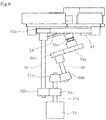
- the first rotator 24 and the second rotator 25 are rotated by separated motors each other, however, it may be possible to rotate using the same motor.
- a spur gear 24b may be integrated to the rotation axis 24a of the first rotator 24 being slant to the horizontal plane.
- the spur gear 24b meshes with a spur gear 50a integrated to a rotation axis 50 at one end side.
- a bevel gear 50b integrated to a rotation axis 50 at the opposite end side meshes with a bevel gear 51b integrated to a rotation axis 51a of a motor 51.
- the following gear 44 of the second rotator 25 meshes with a spur gear 52a integrated to a rotation axis 52 at one end side.
- a spur gear 52b integrated to the rotation axis 52 at the opposite end side meshes with a spur gear 51c integrated to the rotation axis 51a of the motor 51.
- the supply port 13 may be closed when the medicine cassette 5 is detached from the cassette attaching part; however, the medicine dispensing part 7 may be constructed detachably from the medicine cassette 5 and supply port 13 may be closed by the shutter 14 when the medicine dispensing unit 7 is detached therefrom.
Claims (8)
- Une cassette de médecine (5) comprenant une unité de distribution de médicament (7) pour distribuer un médicament retenu, l'unité de distribution de médicament (7) comprenant :un premier rotateur (24) ayant une face circulaire disposée de manière rotative dans un état incliné par rapport à un plan horizontal ;un second rotateur (25) ayant une face annulaire disposée de manière rotative sur le plan horizontal au niveau d'un côté périphérique externe du premier rotateur (24), caractérisée en ce qu'elle comprend en outre un élément de guidage (28) ayant une face de guidage, la face de guidage étant disposée au-dessus de la face circulaire du premier rotateur tout en s'étendant radialement par rapport à la face circulaire, étant positionné vers l'aval dans une direction de rotation du premier rotateur (24) vers une périphérie dans une direction radiale, et pouvant entrer en contact avec le médicament placé sur le premier rotateur (24) en raison de la rotation du premier rotateur (24), de sorte que dans l'élément de guidage (28), au moins une partie comprenant la face de guidage à mettre en contact avec le médicament est capable de se déformer élastiquement de manière à modifier une relation de position avec le second rotateur (25) en fonction de la taille du médicament.
- La cassette de médicament selon la revendication 1, comprenant en outre un second moteur (41) ayant un axe de rotation intégré à un engrenage d'entraînement (42) venant en prise avec un engrenage suiveur (40) intégré à une extrémité inférieure d'un axe de rotation du premier rotateur (24), et dans laquelle le second moteur (41) est configuré pour faire tourner le premier rotateur (24) à une vitesse insuffisante pour déplacer le médicament vers un côté périphérique externe uniquement par une force centrifuge, mais suffisante pour déplacer le médicament vers le côté périphérique externe le long de l'élément de guidage (28).
- La cassette de médicament selon la revendication 2, dans laquelle le deuxième moteur (41) est configuré pour arrêter le premier rotateur (24) chaque fois qu'un médicament est distribué.
- La cassette de médicament selon l'une quelconque des revendications 1 à 3, dans laquelle le premier rotateur (24) et le second rotateur (25) sont mis en rotation par un moyen d'entraînement identique.
- La cassette de médicament selon la revendication 1, comprenant en outre un moteur (51) pourvu d'un axe de rotation (51a), où
le premier rotateur (24) est pourvu d'un axe de rotation (24a) s'étendant obliquement vers le bas et comportant un engrenage droit (24b) à son extrémité inférieure, ledit engrenage droit (24b) coopérant avec un engrenage droit (50a) intégré à une extrémité d'un axe de rotation (50), tandis que son extrémité opposée comporte un engrenage conique (50b) coopérant à son tour avec un engrenage conique (51b) intégré à un axe de rotation (51a) du moteur (51),
le second rotateur (25) est pourvu d'un engrenage suiveur (44) coopérant avec un engrenage droit (52a) intégré à un côté d'extrémité d'un axe de rotation (52) lequel axe de rotation (52), de son côté d'extrémité opposé, a un engrenage droit (52b) coopérant avec un engrenage droit (51c) intégré à l'axe de rotation (51a) du moteur (51),
le moteur (51) est configuré pour arrêter le premier rotateur (24) et le second rotateur (25) chaque fois qu'un médicament est distribué. - La cassette de médicament selon l'une quelconque des revendications 1 à 5, comprenant en outre une unité de fourniture de médicament destinée à fournir le médicament à l'unité de distribution de médicament (7), l'unité de fourniture de médicament étant capable de fournir le médicament en fonction de l'état de réapprovisionnement du médicament à l'unité de distribution de médicament (7).
- La cassette de médicament selon la revendication 6, dans laquelle l'unité de fourniture de médicament est détachable de l'unité de distribution de médicament (7) et comprend un orifice de fourniture (13) destiné à fournir le médicament à l'unité de distribution de médicament (7) et un élément obturateur (14) pour fermer l'orifice de fourniture (13) lorsque l'unité de distribution de médicament (7) est détachée de l'unité de fourniture de médicament.
- La cassette de médicament selon la revendication 7, dans laquelle la cassette de médicament (5) peut être attachée à et détachée d'une pièce de fixation de cassette, et l'élément d'obturateur (14) ferme l'orifice de fourniture (13) de l'unité de distribution de médicament (7) lorsque la cassette de médicament (5) est détachée de la pièce de fixation de cassette.
Applications Claiming Priority (2)
| Application Number | Priority Date | Filing Date | Title |
|---|---|---|---|
| JP2014150196 | 2014-07-23 | ||
| PCT/JP2015/070750 WO2016013553A1 (fr) | 2014-07-23 | 2015-07-21 | Cassette de médicament |
Publications (3)
| Publication Number | Publication Date |
|---|---|
| EP3173060A1 EP3173060A1 (fr) | 2017-05-31 |
| EP3173060A4 EP3173060A4 (fr) | 2018-03-21 |
| EP3173060B1 true EP3173060B1 (fr) | 2019-06-12 |
Family
ID=55163077
Family Applications (1)
| Application Number | Title | Priority Date | Filing Date |
|---|---|---|---|
| EP15825431.8A Active EP3173060B1 (fr) | 2014-07-23 | 2015-07-21 | Cassette de médicament |
Country Status (6)
| Country | Link |
|---|---|
| US (1) | US9877896B2 (fr) |
| EP (1) | EP3173060B1 (fr) |
| JP (1) | JP5867666B1 (fr) |
| KR (1) | KR102360460B1 (fr) |
| CN (1) | CN106535859B (fr) |
| WO (1) | WO2016013553A1 (fr) |
Families Citing this family (13)
| Publication number | Priority date | Publication date | Assignee | Title |
|---|---|---|---|---|
| JP6172489B1 (ja) | 2015-11-30 | 2017-08-02 | 株式会社湯山製作所 | 薬剤カセット、薬剤払出装置、及び薬剤包装装置 |
| JP6736064B2 (ja) * | 2017-01-04 | 2020-08-05 | 株式会社トーショー | 薬剤フィーダ |
| CN107380943A (zh) * | 2017-07-26 | 2017-11-24 | 宜兴新高合金制品有限公司 | 一种质量块螺旋震动输送装置 |
| CA3072585A1 (fr) * | 2017-08-15 | 2019-02-21 | Yuyama Mfg. Co., Ltd. | Dispositif de reglage de trajet de guidage de comprime de cassette de comprimes |
| KR101880924B1 (ko) * | 2017-09-26 | 2018-07-23 | (주)제이브이엠 | 약제 카세트 및 이를 포함하는 약제 자동 포장기 |
| CN107898315B (zh) * | 2017-11-21 | 2020-09-04 | 宿迁市宿城区人民医院 | 一种中医调理药茶冲泡装置及方法 |
| CN108963852B (zh) * | 2018-07-23 | 2020-06-02 | 冯航军 | 一种手选改变弹性元件调压稳件的电力检修工具配发装置 |
| JP7233076B2 (ja) * | 2018-09-21 | 2023-03-06 | 株式会社タカゾノ | 薬剤供給装置 |
| JP2020124327A (ja) * | 2019-02-04 | 2020-08-20 | 株式会社タカゾノ | 薬剤供給装置 |
| CN110884777B (zh) * | 2019-10-18 | 2021-08-27 | 福建师范大学 | 一种可简便分药的药瓶 |
| JP7337383B2 (ja) * | 2020-01-29 | 2023-09-04 | 株式会社トーショー | 薬剤フィーダ |
| CN111824475B (zh) * | 2020-07-17 | 2021-07-23 | 郑州轻工业大学 | 一种粒径可调的片剂药品摆药装置 |
| CN113479954B (zh) * | 2021-08-10 | 2022-01-25 | 宿迁凯达环保设备制造有限公司 | 一种环保的污水处理设备 |
Family Cites Families (13)
| Publication number | Priority date | Publication date | Assignee | Title |
|---|---|---|---|---|
| JP2541997B2 (ja) | 1987-08-12 | 1996-10-09 | ディーエスエム ナムローゼ フェンノートシャップ | 活性エネルギ−線による硬化方法 |
| JPH0651529B2 (ja) * | 1989-11-01 | 1994-07-06 | 株式会社エフアイテイ | 供給機 |
| JP2000203525A (ja) * | 1999-01-11 | 2000-07-25 | Dainippon Printing Co Ltd | 錠剤供給ホッパ― |
| JP2002347921A (ja) | 2001-05-25 | 2002-12-04 | Ntn Corp | 部品供給装置 |
| JP2008127133A (ja) * | 2006-11-17 | 2008-06-05 | Nakamichi:Kk | パーツフィーダ |
| JP3148073U (ja) * | 2008-11-16 | 2009-01-29 | 木下精工有限会社 | 部品供給装置 |
| TWI585017B (zh) * | 2009-08-28 | 2017-06-01 | Yuyama Manufacturing Co Ltd | A medicine discharge device, a hopper, and a method for manufacturing the same |
| KR101820799B1 (ko) * | 2010-12-09 | 2018-01-22 | 가부시키가이샤 유야마 세이사쿠쇼 | 약제 송출 장치 및 약제 계수 장치 |
| US9155681B2 (en) * | 2011-01-20 | 2015-10-13 | Yuyama Mfg. Co., Ltd. | Medicine feeding device and a medicine counting device using the medicine feeding device |
| US9242785B2 (en) * | 2011-09-06 | 2016-01-26 | Yuyama Mfg. Co., Ltd. | Medicine cassette and medicine feeding apparatus |
| WO2013141130A1 (fr) * | 2012-03-21 | 2013-09-26 | 株式会社湯山製作所 | Dispositif d'alimentation en médicament et dispositif de comptage de médicament |
| KR20130118838A (ko) | 2013-08-02 | 2013-10-30 | 임도현 | 조준경의 영점 조정방법 |
| WO2015052794A1 (fr) * | 2013-10-09 | 2015-04-16 | 株式会社タカゾノテクノロジー | Dispositif de remplissage de médicament |
-
2015
- 2015-07-21 KR KR1020177001531A patent/KR102360460B1/ko active IP Right Grant
- 2015-07-21 WO PCT/JP2015/070750 patent/WO2016013553A1/fr active Application Filing
- 2015-07-21 EP EP15825431.8A patent/EP3173060B1/fr active Active
- 2015-07-21 US US15/328,431 patent/US9877896B2/en active Active
- 2015-07-21 CN CN201580038136.4A patent/CN106535859B/zh active Active
- 2015-07-21 JP JP2015548097A patent/JP5867666B1/ja active Active
Non-Patent Citations (1)
| Title |
|---|
| None * |
Also Published As
| Publication number | Publication date |
|---|---|
| KR102360460B1 (ko) | 2022-02-10 |
| CN106535859B (zh) | 2019-06-14 |
| JP5867666B1 (ja) | 2016-02-24 |
| WO2016013553A1 (fr) | 2016-01-28 |
| EP3173060A1 (fr) | 2017-05-31 |
| EP3173060A4 (fr) | 2018-03-21 |
| US9877896B2 (en) | 2018-01-30 |
| CN106535859A (zh) | 2017-03-22 |
| US20170216150A1 (en) | 2017-08-03 |
| KR20170034383A (ko) | 2017-03-28 |
| JPWO2016013553A1 (ja) | 2017-04-27 |
Similar Documents
| Publication | Publication Date | Title |
|---|---|---|
| EP3173060B1 (fr) | Cassette de médicament | |
| JP6135742B2 (ja) | 薬剤排出装置 | |
| US7669733B2 (en) | Cassette device for automatic medicine packaging apparatus | |
| US9233789B2 (en) | Medicine-supplying device and medicine-counting device | |
| US8281955B2 (en) | Passive device for staging and dispensing objects | |
| US8244398B2 (en) | Device for selectively presenting objects | |
| CN108119345A (zh) | 蠕动泵装置 | |
| KR200459198Y1 (ko) | 로터리형 정제공급기 | |
| JP2023052649A (ja) | 薬剤包装装置 | |
| KR100623387B1 (ko) | 가루약 분배장치 | |
| CN114348363B (zh) | 一种含有顶槽的可调节高度的制药用颗粒分装机 | |
| US20220332493A1 (en) | Vacuum-based retrieving and dispensing | |
| JP4837641B2 (ja) | 散薬分配装置 | |
| CA3076226A1 (fr) | Cartouche de distribution de pilules | |
| JP7337382B2 (ja) | 薬剤フィーダ | |
| JP4852114B2 (ja) | 散薬分配装置および分包機 | |
| JP7337383B2 (ja) | 薬剤フィーダ | |
| CN115966486A (zh) | 基板处理装置及基板处理方法 | |
| JP7325756B2 (ja) | 薬剤フィーダ | |
| JP7160290B2 (ja) | 遠心機、及びそれを用いた懸濁液調製方法 | |
| KR100613020B1 (ko) | 가루약 피이더 | |
| JP6370678B2 (ja) | 基板液処理装置 | |
| KR20220090958A (ko) | 약제 카트리지 건조 장치 | |
| KR20170027972A (ko) | 개폐장치 및 이를 포함하는 약제 조제 시스템 |
Legal Events
| Date | Code | Title | Description |
|---|---|---|---|
| STAA | Information on the status of an ep patent application or granted ep patent |
Free format text: STATUS: THE INTERNATIONAL PUBLICATION HAS BEEN MADE |
|
| PUAI | Public reference made under article 153(3) epc to a published international application that has entered the european phase |
Free format text: ORIGINAL CODE: 0009012 |
|
| STAA | Information on the status of an ep patent application or granted ep patent |
Free format text: STATUS: REQUEST FOR EXAMINATION WAS MADE |
|
| 17P | Request for examination filed |
Effective date: 20170221 |
|
| AK | Designated contracting states |
Kind code of ref document: A1 Designated state(s): AL AT BE BG CH CY CZ DE DK EE ES FI FR GB GR HR HU IE IS IT LI LT LU LV MC MK MT NL NO PL PT RO RS SE SI SK SM TR |
|
| AX | Request for extension of the european patent |
Extension state: BA ME |
|
| DAV | Request for validation of the european patent (deleted) | ||
| DAX | Request for extension of the european patent (deleted) | ||
| A4 | Supplementary search report drawn up and despatched |
Effective date: 20180216 |
|
| RIC1 | Information provided on ipc code assigned before grant |
Ipc: A61J 3/00 20060101AFI20180212BHEP Ipc: B65B 1/30 20060101ALI20180212BHEP Ipc: B65B 37/08 20060101ALI20180212BHEP |
|
| STAA | Information on the status of an ep patent application or granted ep patent |
Free format text: STATUS: EXAMINATION IS IN PROGRESS |
|
| 17Q | First examination report despatched |
Effective date: 20180827 |
|
| GRAP | Despatch of communication of intention to grant a patent |
Free format text: ORIGINAL CODE: EPIDOSNIGR1 |
|
| STAA | Information on the status of an ep patent application or granted ep patent |
Free format text: STATUS: GRANT OF PATENT IS INTENDED |
|
| INTG | Intention to grant announced |
Effective date: 20190211 |
|
| GRAJ | Information related to disapproval of communication of intention to grant by the applicant or resumption of examination proceedings by the epo deleted |
Free format text: ORIGINAL CODE: EPIDOSDIGR1 |
|
| STAA | Information on the status of an ep patent application or granted ep patent |
Free format text: STATUS: EXAMINATION IS IN PROGRESS |
|
| GRAS | Grant fee paid |
Free format text: ORIGINAL CODE: EPIDOSNIGR3 |
|
| STAA | Information on the status of an ep patent application or granted ep patent |
Free format text: STATUS: GRANT OF PATENT IS INTENDED |
|
| GRAP | Despatch of communication of intention to grant a patent |
Free format text: ORIGINAL CODE: EPIDOSNIGR1 |
|
| INTC | Intention to grant announced (deleted) | ||
| GRAA | (expected) grant |
Free format text: ORIGINAL CODE: 0009210 |
|
| STAA | Information on the status of an ep patent application or granted ep patent |
Free format text: STATUS: THE PATENT HAS BEEN GRANTED |
|
| INTG | Intention to grant announced |
Effective date: 20190424 |
|
| AK | Designated contracting states |
Kind code of ref document: B1 Designated state(s): AL AT BE BG CH CY CZ DE DK EE ES FI FR GB GR HR HU IE IS IT LI LT LU LV MC MK MT NL NO PL PT RO RS SE SI SK SM TR |
|
| REG | Reference to a national code |
Ref country code: GB Ref legal event code: FG4D |
|
| REG | Reference to a national code |
Ref country code: CH Ref legal event code: EP |
|
| REG | Reference to a national code |
Ref country code: AT Ref legal event code: REF Ref document number: 1141650 Country of ref document: AT Kind code of ref document: T Effective date: 20190615 |
|
| REG | Reference to a national code |
Ref country code: DE Ref legal event code: R096 Ref document number: 602015031986 Country of ref document: DE |
|
| REG | Reference to a national code |
Ref country code: IE Ref legal event code: FG4D |
|
| REG | Reference to a national code |
Ref country code: NL Ref legal event code: FP |
|
| REG | Reference to a national code |
Ref country code: LT Ref legal event code: MG4D |
|
| PG25 | Lapsed in a contracting state [announced via postgrant information from national office to epo] |
Ref country code: LT Free format text: LAPSE BECAUSE OF FAILURE TO SUBMIT A TRANSLATION OF THE DESCRIPTION OR TO PAY THE FEE WITHIN THE PRESCRIBED TIME-LIMIT Effective date: 20190612 Ref country code: NO Free format text: LAPSE BECAUSE OF FAILURE TO SUBMIT A TRANSLATION OF THE DESCRIPTION OR TO PAY THE FEE WITHIN THE PRESCRIBED TIME-LIMIT Effective date: 20190912 Ref country code: HR Free format text: LAPSE BECAUSE OF FAILURE TO SUBMIT A TRANSLATION OF THE DESCRIPTION OR TO PAY THE FEE WITHIN THE PRESCRIBED TIME-LIMIT Effective date: 20190612 Ref country code: FI Free format text: LAPSE BECAUSE OF FAILURE TO SUBMIT A TRANSLATION OF THE DESCRIPTION OR TO PAY THE FEE WITHIN THE PRESCRIBED TIME-LIMIT Effective date: 20190612 Ref country code: SE Free format text: LAPSE BECAUSE OF FAILURE TO SUBMIT A TRANSLATION OF THE DESCRIPTION OR TO PAY THE FEE WITHIN THE PRESCRIBED TIME-LIMIT Effective date: 20190612 Ref country code: AL Free format text: LAPSE BECAUSE OF FAILURE TO SUBMIT A TRANSLATION OF THE DESCRIPTION OR TO PAY THE FEE WITHIN THE PRESCRIBED TIME-LIMIT Effective date: 20190612 |
|
| PG25 | Lapsed in a contracting state [announced via postgrant information from national office to epo] |
Ref country code: LV Free format text: LAPSE BECAUSE OF FAILURE TO SUBMIT A TRANSLATION OF THE DESCRIPTION OR TO PAY THE FEE WITHIN THE PRESCRIBED TIME-LIMIT Effective date: 20190612 Ref country code: GR Free format text: LAPSE BECAUSE OF FAILURE TO SUBMIT A TRANSLATION OF THE DESCRIPTION OR TO PAY THE FEE WITHIN THE PRESCRIBED TIME-LIMIT Effective date: 20190913 Ref country code: BG Free format text: LAPSE BECAUSE OF FAILURE TO SUBMIT A TRANSLATION OF THE DESCRIPTION OR TO PAY THE FEE WITHIN THE PRESCRIBED TIME-LIMIT Effective date: 20190912 Ref country code: RS Free format text: LAPSE BECAUSE OF FAILURE TO SUBMIT A TRANSLATION OF THE DESCRIPTION OR TO PAY THE FEE WITHIN THE PRESCRIBED TIME-LIMIT Effective date: 20190612 |
|
| REG | Reference to a national code |
Ref country code: AT Ref legal event code: MK05 Ref document number: 1141650 Country of ref document: AT Kind code of ref document: T Effective date: 20190612 |
|
| PG25 | Lapsed in a contracting state [announced via postgrant information from national office to epo] |
Ref country code: PT Free format text: LAPSE BECAUSE OF FAILURE TO SUBMIT A TRANSLATION OF THE DESCRIPTION OR TO PAY THE FEE WITHIN THE PRESCRIBED TIME-LIMIT Effective date: 20191014 Ref country code: CZ Free format text: LAPSE BECAUSE OF FAILURE TO SUBMIT A TRANSLATION OF THE DESCRIPTION OR TO PAY THE FEE WITHIN THE PRESCRIBED TIME-LIMIT Effective date: 20190612 Ref country code: RO Free format text: LAPSE BECAUSE OF FAILURE TO SUBMIT A TRANSLATION OF THE DESCRIPTION OR TO PAY THE FEE WITHIN THE PRESCRIBED TIME-LIMIT Effective date: 20190612 Ref country code: SK Free format text: LAPSE BECAUSE OF FAILURE TO SUBMIT A TRANSLATION OF THE DESCRIPTION OR TO PAY THE FEE WITHIN THE PRESCRIBED TIME-LIMIT Effective date: 20190612 Ref country code: AT Free format text: LAPSE BECAUSE OF FAILURE TO SUBMIT A TRANSLATION OF THE DESCRIPTION OR TO PAY THE FEE WITHIN THE PRESCRIBED TIME-LIMIT Effective date: 20190612 Ref country code: EE Free format text: LAPSE BECAUSE OF FAILURE TO SUBMIT A TRANSLATION OF THE DESCRIPTION OR TO PAY THE FEE WITHIN THE PRESCRIBED TIME-LIMIT Effective date: 20190612 |
|
| RAP2 | Party data changed (patent owner data changed or rights of a patent transferred) |
Owner name: YUYAMA MFG. CO., LTD. |
|
| PG25 | Lapsed in a contracting state [announced via postgrant information from national office to epo] |
Ref country code: SM Free format text: LAPSE BECAUSE OF FAILURE TO SUBMIT A TRANSLATION OF THE DESCRIPTION OR TO PAY THE FEE WITHIN THE PRESCRIBED TIME-LIMIT Effective date: 20190612 Ref country code: IS Free format text: LAPSE BECAUSE OF FAILURE TO SUBMIT A TRANSLATION OF THE DESCRIPTION OR TO PAY THE FEE WITHIN THE PRESCRIBED TIME-LIMIT Effective date: 20191012 Ref country code: IT Free format text: LAPSE BECAUSE OF FAILURE TO SUBMIT A TRANSLATION OF THE DESCRIPTION OR TO PAY THE FEE WITHIN THE PRESCRIBED TIME-LIMIT Effective date: 20190612 Ref country code: ES Free format text: LAPSE BECAUSE OF FAILURE TO SUBMIT A TRANSLATION OF THE DESCRIPTION OR TO PAY THE FEE WITHIN THE PRESCRIBED TIME-LIMIT Effective date: 20190612 |
|
| REG | Reference to a national code |
Ref country code: CH Ref legal event code: PL |
|
| REG | Reference to a national code |
Ref country code: DE Ref legal event code: R097 Ref document number: 602015031986 Country of ref document: DE |
|
| PG25 | Lapsed in a contracting state [announced via postgrant information from national office to epo] |
Ref country code: MC Free format text: LAPSE BECAUSE OF FAILURE TO SUBMIT A TRANSLATION OF THE DESCRIPTION OR TO PAY THE FEE WITHIN THE PRESCRIBED TIME-LIMIT Effective date: 20190612 Ref country code: TR Free format text: LAPSE BECAUSE OF FAILURE TO SUBMIT A TRANSLATION OF THE DESCRIPTION OR TO PAY THE FEE WITHIN THE PRESCRIBED TIME-LIMIT Effective date: 20190612 |
|
| REG | Reference to a national code |
Ref country code: BE Ref legal event code: MM Effective date: 20190731 |
|
| PLBE | No opposition filed within time limit |
Free format text: ORIGINAL CODE: 0009261 |
|
| STAA | Information on the status of an ep patent application or granted ep patent |
Free format text: STATUS: NO OPPOSITION FILED WITHIN TIME LIMIT |
|
| PG25 | Lapsed in a contracting state [announced via postgrant information from national office to epo] |
Ref country code: PL Free format text: LAPSE BECAUSE OF FAILURE TO SUBMIT A TRANSLATION OF THE DESCRIPTION OR TO PAY THE FEE WITHIN THE PRESCRIBED TIME-LIMIT Effective date: 20190612 Ref country code: DK Free format text: LAPSE BECAUSE OF FAILURE TO SUBMIT A TRANSLATION OF THE DESCRIPTION OR TO PAY THE FEE WITHIN THE PRESCRIBED TIME-LIMIT Effective date: 20190612 |
|
| 26N | No opposition filed |
Effective date: 20200313 |
|
| PG25 | Lapsed in a contracting state [announced via postgrant information from national office to epo] |
Ref country code: LU Free format text: LAPSE BECAUSE OF NON-PAYMENT OF DUE FEES Effective date: 20190721 Ref country code: LI Free format text: LAPSE BECAUSE OF NON-PAYMENT OF DUE FEES Effective date: 20190731 Ref country code: IS Free format text: LAPSE BECAUSE OF FAILURE TO SUBMIT A TRANSLATION OF THE DESCRIPTION OR TO PAY THE FEE WITHIN THE PRESCRIBED TIME-LIMIT Effective date: 20200224 Ref country code: SI Free format text: LAPSE BECAUSE OF FAILURE TO SUBMIT A TRANSLATION OF THE DESCRIPTION OR TO PAY THE FEE WITHIN THE PRESCRIBED TIME-LIMIT Effective date: 20190612 Ref country code: CH Free format text: LAPSE BECAUSE OF NON-PAYMENT OF DUE FEES Effective date: 20190731 Ref country code: BE Free format text: LAPSE BECAUSE OF NON-PAYMENT OF DUE FEES Effective date: 20190731 |
|
| PG2D | Information on lapse in contracting state deleted |
Ref country code: IS |
|
| PG25 | Lapsed in a contracting state [announced via postgrant information from national office to epo] |
Ref country code: IE Free format text: LAPSE BECAUSE OF NON-PAYMENT OF DUE FEES Effective date: 20190721 |
|
| GBPC | Gb: european patent ceased through non-payment of renewal fee |
Effective date: 20190912 |
|
| PG25 | Lapsed in a contracting state [announced via postgrant information from national office to epo] |
Ref country code: GB Free format text: LAPSE BECAUSE OF NON-PAYMENT OF DUE FEES Effective date: 20190912 |
|
| PG25 | Lapsed in a contracting state [announced via postgrant information from national office to epo] |
Ref country code: CY Free format text: LAPSE BECAUSE OF FAILURE TO SUBMIT A TRANSLATION OF THE DESCRIPTION OR TO PAY THE FEE WITHIN THE PRESCRIBED TIME-LIMIT Effective date: 20190612 |
|
| PG25 | Lapsed in a contracting state [announced via postgrant information from national office to epo] |
Ref country code: MT Free format text: LAPSE BECAUSE OF FAILURE TO SUBMIT A TRANSLATION OF THE DESCRIPTION OR TO PAY THE FEE WITHIN THE PRESCRIBED TIME-LIMIT Effective date: 20190612 Ref country code: HU Free format text: LAPSE BECAUSE OF FAILURE TO SUBMIT A TRANSLATION OF THE DESCRIPTION OR TO PAY THE FEE WITHIN THE PRESCRIBED TIME-LIMIT; INVALID AB INITIO Effective date: 20150721 |
|
| PG25 | Lapsed in a contracting state [announced via postgrant information from national office to epo] |
Ref country code: MK Free format text: LAPSE BECAUSE OF FAILURE TO SUBMIT A TRANSLATION OF THE DESCRIPTION OR TO PAY THE FEE WITHIN THE PRESCRIBED TIME-LIMIT Effective date: 20190612 |
|
| PGFP | Annual fee paid to national office [announced via postgrant information from national office to epo] |
Ref country code: NL Payment date: 20230719 Year of fee payment: 9 |
|
| PGFP | Annual fee paid to national office [announced via postgrant information from national office to epo] |
Ref country code: FR Payment date: 20230726 Year of fee payment: 9 Ref country code: DE Payment date: 20230719 Year of fee payment: 9 |