EP3173060B1 - Medicine cassette - Google Patents
Medicine cassette Download PDFInfo
- Publication number
- EP3173060B1 EP3173060B1 EP15825431.8A EP15825431A EP3173060B1 EP 3173060 B1 EP3173060 B1 EP 3173060B1 EP 15825431 A EP15825431 A EP 15825431A EP 3173060 B1 EP3173060 B1 EP 3173060B1
- Authority
- EP
- European Patent Office
- Prior art keywords
- medicine
- rotator
- cassette
- rotation axis
- motor
- Prior art date
- Legal status (The legal status is an assumption and is not a legal conclusion. Google has not performed a legal analysis and makes no representation as to the accuracy of the status listed.)
- Active
Links
- 239000003814 drug Substances 0.000 title claims description 195
- 229940079593 drug Drugs 0.000 title description 60
- 230000002093 peripheral effect Effects 0.000 claims description 16
- 230000000717 retained effect Effects 0.000 claims description 4
- 230000000052 comparative effect Effects 0.000 description 12
- 239000003826 tablet Substances 0.000 description 12
- 238000010276 construction Methods 0.000 description 7
- 230000033001 locomotion Effects 0.000 description 6
- 238000004806 packaging method and process Methods 0.000 description 6
- 238000002474 experimental method Methods 0.000 description 4
- 230000001105 regulatory effect Effects 0.000 description 3
- 238000004891 communication Methods 0.000 description 2
- 230000005489 elastic deformation Effects 0.000 description 2
- 239000000463 material Substances 0.000 description 2
- 238000000034 method Methods 0.000 description 2
- 230000008569 process Effects 0.000 description 2
- 238000011144 upstream manufacturing Methods 0.000 description 2
- 238000005299 abrasion Methods 0.000 description 1
- 230000009471 action Effects 0.000 description 1
- 239000002775 capsule Substances 0.000 description 1
- 230000008859 change Effects 0.000 description 1
- LYKJEJVAXSGWAJ-UHFFFAOYSA-N compactone Natural products CC1(C)CCCC2(C)C1CC(=O)C3(O)CC(C)(CCC23)C=C LYKJEJVAXSGWAJ-UHFFFAOYSA-N 0.000 description 1
- 239000007947 dispensing tablet Substances 0.000 description 1
- 238000006073 displacement reaction Methods 0.000 description 1
- 230000000694 effects Effects 0.000 description 1
- 238000009472 formulation Methods 0.000 description 1
- 230000003116 impacting effect Effects 0.000 description 1
- 238000009434 installation Methods 0.000 description 1
- 239000011159 matrix material Substances 0.000 description 1
- 239000000203 mixture Substances 0.000 description 1
- 238000012986 modification Methods 0.000 description 1
- 230000004048 modification Effects 0.000 description 1
- 230000004044 response Effects 0.000 description 1
- 229920002379 silicone rubber Polymers 0.000 description 1
- 239000004945 silicone rubber Substances 0.000 description 1
- 239000007787 solid Substances 0.000 description 1
- 238000012546 transfer Methods 0.000 description 1
Images


Classifications
-
- A—HUMAN NECESSITIES
- A61—MEDICAL OR VETERINARY SCIENCE; HYGIENE
- A61J—CONTAINERS SPECIALLY ADAPTED FOR MEDICAL OR PHARMACEUTICAL PURPOSES; DEVICES OR METHODS SPECIALLY ADAPTED FOR BRINGING PHARMACEUTICAL PRODUCTS INTO PARTICULAR PHYSICAL OR ADMINISTERING FORMS; DEVICES FOR ADMINISTERING FOOD OR MEDICINES ORALLY; BABY COMFORTERS; DEVICES FOR RECEIVING SPITTLE
- A61J3/00—Devices or methods specially adapted for bringing pharmaceutical products into particular physical or administering forms
-
- A—HUMAN NECESSITIES
- A61—MEDICAL OR VETERINARY SCIENCE; HYGIENE
- A61J—CONTAINERS SPECIALLY ADAPTED FOR MEDICAL OR PHARMACEUTICAL PURPOSES; DEVICES OR METHODS SPECIALLY ADAPTED FOR BRINGING PHARMACEUTICAL PRODUCTS INTO PARTICULAR PHYSICAL OR ADMINISTERING FORMS; DEVICES FOR ADMINISTERING FOOD OR MEDICINES ORALLY; BABY COMFORTERS; DEVICES FOR RECEIVING SPITTLE
- A61J7/00—Devices for administering medicines orally, e.g. spoons; Pill counting devices; Arrangements for time indication or reminder for taking medicine
- A61J7/0076—Medicament distribution means
-
- B—PERFORMING OPERATIONS; TRANSPORTING
- B65—CONVEYING; PACKING; STORING; HANDLING THIN OR FILAMENTARY MATERIAL
- B65B—MACHINES, APPARATUS OR DEVICES FOR, OR METHODS OF, PACKAGING ARTICLES OR MATERIALS; UNPACKING
- B65B1/00—Packaging fluent solid material, e.g. powders, granular or loose fibrous material, loose masses of small articles, in individual containers or receptacles, e.g. bags, sacks, boxes, cartons, cans, or jars
- B65B1/30—Devices or methods for controlling or determining the quantity or quality or the material fed or filled
-
- B—PERFORMING OPERATIONS; TRANSPORTING
- B65—CONVEYING; PACKING; STORING; HANDLING THIN OR FILAMENTARY MATERIAL
- B65B—MACHINES, APPARATUS OR DEVICES FOR, OR METHODS OF, PACKAGING ARTICLES OR MATERIALS; UNPACKING
- B65B37/00—Supplying or feeding fluent-solid, plastic, or liquid material, or loose masses of small articles, to be packaged
- B65B37/08—Supplying or feeding fluent-solid, plastic, or liquid material, or loose masses of small articles, to be packaged by rotary feeders
-
- B—PERFORMING OPERATIONS; TRANSPORTING
- B65—CONVEYING; PACKING; STORING; HANDLING THIN OR FILAMENTARY MATERIAL
- B65D—CONTAINERS FOR STORAGE OR TRANSPORT OF ARTICLES OR MATERIALS, e.g. BAGS, BARRELS, BOTTLES, BOXES, CANS, CARTONS, CRATES, DRUMS, JARS, TANKS, HOPPERS, FORWARDING CONTAINERS; ACCESSORIES, CLOSURES, OR FITTINGS THEREFOR; PACKAGING ELEMENTS; PACKAGES
- B65D83/00—Containers or packages with special means for dispensing contents
- B65D83/04—Containers or packages with special means for dispensing contents for dispensing annular, disc-shaped, or spherical or like small articles, e.g. tablets or pills
- B65D83/0409—Containers or packages with special means for dispensing contents for dispensing annular, disc-shaped, or spherical or like small articles, e.g. tablets or pills the dispensing means being adapted for delivering one article, or a single dose, upon each actuation
-
- B—PERFORMING OPERATIONS; TRANSPORTING
- B65—CONVEYING; PACKING; STORING; HANDLING THIN OR FILAMENTARY MATERIAL
- B65G—TRANSPORT OR STORAGE DEVICES, e.g. CONVEYORS FOR LOADING OR TIPPING, SHOP CONVEYOR SYSTEMS OR PNEUMATIC TUBE CONVEYORS
- B65G29/00—Rotary conveyors, e.g. rotating discs, arms, star-wheels or cones
-
- B—PERFORMING OPERATIONS; TRANSPORTING
- B65—CONVEYING; PACKING; STORING; HANDLING THIN OR FILAMENTARY MATERIAL
- B65G—TRANSPORT OR STORAGE DEVICES, e.g. CONVEYORS FOR LOADING OR TIPPING, SHOP CONVEYOR SYSTEMS OR PNEUMATIC TUBE CONVEYORS
- B65G2201/00—Indexing codes relating to handling devices, e.g. conveyors, characterised by the type of product or load being conveyed or handled
- B65G2201/02—Articles
- B65G2201/027—Tablets, capsules, pills or the like
Definitions
- the present invention relates to a medicine cassette.
- WO 2013/035692 discloses a medicine supply device comprising a tube-shaped body housing a first rotating body to form together a medicine containing section capable of containing a medicine.
- the first rotating body can reciprocate in the axial direction of the tube-shaped body and is rotatable about a first rotation axis.
- the device comprises also a second rotating body disposed at the outer periphery of the opening of the tube-shaped body and rotatable about a second rotation axis. Owing to such configuration the device can contain a large amount of medicine, while being capable of smoothly and automatically dispensing the medicine.
- the present invention may provide a medicine cassette comprising a medicine dispensing unit for dispensing a medicine retained, the medicine dispensing unit may comprise a first rotator having a circular face rotatably disposed at a slant state to a horizontal plane; a second rotator having a ring face rotatably disposed over the horizontal plane at an outer peripheral side of the first rotator; and a guide member having a guide face, the guide face being disposed above the circular face of the first rotator while extending radially with respect to the circular face, being positioned at a downstream side in a rotational direction of the first rotator towards a periphery in a radial direction, and being capable of contacting to the medicine placed on the first rotator due to rotation of the first rotator.
- the medicine moves toward a circumference direction according to the rotation thereof to contact with the guide face of the guide member and then moves to a radially outer side along the guide face. Therefore, even though the first rotator is not rotated at high speeds, the medicine may be moved smoothly to the radially outer side by the guide member.
- At least a part including the guide face to be contacted to the medicine is capable of deforming elastically so as to modify a positional relationship to the second rotator depending on a size of the medicine.
- the first rotator is rotated at a rate at which the medicine is not allowed to move to an outer peripheral side only by a centrifugal force, but is allowed to move to the outer peripheral side along the guide member.
- first rotator and the second rotator are rotated by an identical driver means.
- the construction may be simplified and a compact one. This may be arisen from the fact that there is no need for increasing a rotation speed of the first rotator by disposing the guide member of the above feature. Besides, since a rotation speed of the second rotator may be suppressed so that dispensing accuracy for dispensing certainly the medicine one by one may be improved.
- first rotator and the second rotator are stopped every time one medicine is dispensed.
- the medicine may be dispensed certainly one by one.
- this feature may be effective when the first rotator and the second rotator are rotated by an identical driver means.
- a medicine supplying unit for supplying the medicine to the medicine dispensing unit is disposed and that the medicine supplying unit is capable of supplying the medicine depending on replenishment status of the medicine at the medicine dispensing unit.
- amounts of medicines at the medicine dispensing unit may be always controlled to values suitable for dispensing action.
- the medicine supplying unit is detachable from the medicine dispensing unit and comprises a supply port for supplying the medicine to the medicine dispensing unit and a shutter member for closing the supply port when the medicine dispensing unit is detached from the medicine supplying unit.
- the supply port may be closed by the shutter member so that falling down of the medicines may be protected as for safe handling when the medicines stay in the medicine supplying unit.
- the medicine cassette is attachable to and detachable from a cassette attaching part, and the shutter member closes the supply port of the medicine dispensing unit when the medicine cassette is detached from the cassette attaching part.
- the medicine cassette when there are necessities for supplying the medicines, the medicine cassette may be detached from the cassette attaching part and since the supply port is closed by the shutter member so that there may be no care about spilling out of the medicines even though the medicines remain in the medicine supply unit.
- the medicines since the guide member is provided, the medicines may be moved smoothly to the second rotator if a rotation speed of the first rotator is not fast.
- the medicines may be dispensed certainly one by one.
- the medicine cassette 5 comprises, as shown in Fig. 2 , a medicine reserving unit 6 and a medicine dispensing unit 7.
- the medicine reserving unit 6 is constructed by disposing a supplying rotator 9 in a reserving container 8.
- a plurality of medicines 10 of the same kind e.g. tablet or capsule
- the reserving container 8 as shown in Fig. 3 , comprises a surrounding wall 11 which has an almost trapezoid shape in a top view.
- a guide wall 12 extending downwardly and slantingly is formed on one inner face of a side wall which constructs the surrounding wall 11.
- the medicines 10 may be supplied using this guide wall 12.
- the guide wall 12 allows the supplied medicines 10 to move smoothly toward a bottom plane side and prevents the medicines 10 from being damaged by impacting the bottom plane side strongly.
- a supply port 13 is formed at a lower side below a region to which the guide wall 12 is formed.
- the supply port 13 may be capable of being opened and closed by a shutter 14 which constructs a shutter member of the present invention.
- the shutter 14 may preferably be configured to automatically close when the medicine cassette 5 is detached from the cassette attaching part.
- the supply port 13 may be closed by the shutter 14 biased by a springs etc. and a contact portion is disposed to the cassette attaching part such that a part of the shutter 14 may contact to the contact portion so as to open the supply port 13.
- the supplying rotator 9 has a circular shape and comprises an outer peripheral gear 17 as shown in Fig. 4 .
- a plurality of ridges 18 extend radially outwardly from a rotation center on an upper face.
- the outer peripheral gear 17 meshes with a first gear 19 and a second gear 20 sequentially and the second gear 20 is integrated to a rotation axis of a first motor 21.
- driving force of the first motor 21 may be transferred to the supplying rotator 9 through the second gear 20 and the first gear 19.
- the first motor 21 may be capable of rotating positively and negatively.
- the ridges 18 extend outwardly and evenly from the rotation axis to a radially outward peripheral side, and in detailed description extend curvedly with gradual displacements toward an upstream side in a rotational direction.
- the supporting container 22 is constructed with a surrounding side wall and a bottom wall and each of the supporting member 23, the height regulation member 26 and the width regulation member 27 may be fixed by screwing thereto.
- a discharge port 29 for the medicines 10 is formed.
- the medicines 10 discharged from the discharge port 29, as shown in Fig. 3 may be countably detected by a sensor 30.
- a rectangular protrusion part 31 with a slant top face is formed at the bottom wall and a cylinder part 32 is formed at a center thereof for rotatably supporting the first rotator 24.
- an arch part 33 protrudes in the condition in which a part of a cylinder shape about a center axis of the cylinder part 32 is cut off.
- An inner face of the arch part 33 and the slant upper face of the first rotator 24 construct a reserving concave part 34 (see Fig. 5 ).
- a ring part 35 is formed around the arch part 33.
- the second rotator 25 is mounted.
- Driving force of a third motor 45 may be transferred to the second rotator part 25 from a driving gear 46 which is mentioned below through a communication opening 36 formed by cutting off a part of the reserving concave part 34.
- the supporting member 23 is disposed in the concave of the supporting container 22 and is fixed by screwing from a lower face side.
- a part of the supporting member 23 is constructed with a protrusion part 37.
- An inner face of the protrusion part 37 constructs a part of an inner face surrounding an outer peripheral part of the second rotator 25.
- the guide member 28 may be fixed by screwing on an upper face of the protrusion part 37.
- a following gear 40 is integrated.
- a driving gear 42 which is integrated to a rotation axis of the second motor 41, meshes with the following gear 40. Thereby, the driving force of the second motor 41 may be transferred to the first rotator 24 through the driving gear 42 and the following gear 40.
- the second rotator 25 is, as shown in Fig. 7 , a planar ring plate which is disposed at the outer periphery of the first rotator 24.
- the second rotator 25 is disposed such that the upper face i.e. the ring face, is disposed so as to be positioned over a horizontal face.
- the cylinder part 43 is formed at a lower face side of the second rotator 25 and a following gear 44 is formed at an outer peripheral face thereof.
- a driving gear 46 as shown in Fig. 8 , which is integrated to a rotation axis of the third motor 45, meshes with the following gear 44. Thereby, the driving force of the third motor 45 may be transferred to the second rotator 25 through the driving gear 46 and the following gear 44.
- the height regulation member 26 is shaped generally to a rectangular solid and provides a space between a bottom face thereof and the second rotator 25 when fixed by screwing to a side wall of the supporting container 22.
- the space may be adjusted by changing a screwing position for fixing so as to allow only one medicine 10 to pass through.
- the width regulation member 27 comprises a curved surface 47.
- the width regulation member 27 is fixed by screwing to the side wall of the supporting container 22 and is disposed so as to extend inwardly beyond the outer periphery of the second rotator 25 for regulating an exposed width size of an upper face of the second rotator 25 so that only one medicine 10 may be carried by the second rotator 25.
- the exposed width size may be adjusted by changing a screwing position for fixing.
- the guide member 28 is constructed by a support member 48 and a guide chip 49.
- the support member 48 is formed to about an "L" letter shape from a planar plate and a through hole for fixing to the support member 23 by screwing is formed at one end side.
- the strip shaped guide chip 49 is fixed at a right angled direction against the upper face of the first rotator 24 in the condition out of contact.
- a material having flexibility as well as an excellent anti-abrasion property such as a silicone rubber may be used.
- the guide chip 49 curves gradually to a downstream side of the rotational direction of the first rotator 24 against a radial direction to which the opposite end of the supporting member 48 extends (in Fig. 6 , shown by two dotted line). Thereby, the guide face, which swells out to the outer radial side of the first rotator 24, may be formed.
- the medicine 10 may be moved to an outer radial side by an elastic deformation thereof.
- a tip position of the guide chip 49 reaches adjacent to an inner peripheral edge of the second rotator 25 and is located at a shifted position toward the rotational direction from the position where a stepwise difference between the upper face of the first rotator 24 and the upper face of the second rotator 25 becomes almost zero (in Fig. 6 , though a pressured contacting state of the medicine 10 to the guide chip 49 is not illustrated, the guide chip 49 will be curved by the pressurized contact of the medicine 10.). Since the tip position of the guide chip 49 is set as described above, the guide chip 49 does not hinder the rotational movement of the second rotator 25 and the medicine 10 can certainly be moved onto the second rotator 25 from the first rotator 24.
- the tip of the guide chip 49 of the guide member 28 is located at the position where the tip is rotated at about 40 degrees - about 45 degrees from a referenced position at which the stepwise difference between the slant first rotator 24 and the second rotator 25 becomes zero.
- the height regulation member 26 is disposed at about 90 degrees rotated position from the referenced position such that the height size of the medicine 10 may be regulated.
- the width regulation member 27 is positioned at about 180 degrees rotated position from the referenced position.
- the controller unit 4 executes motion control for the first motor 21, the second motor 41, and the third motor 45 on the basis of sensor signals of the sensor 30 as well as formulation data from a server (not shown) to carry out the dispensing process as described hereunder.
- the centrifugal force exerted to the medicine 10 becomes insufficient.
- the rotation speed of the first rotator 24 becomes high, slipping contact speeds between the medicines 10 and the first rotator 24 become increased and conditions in which the medicines 10 are easy to be damaged are created.
- the rotation speed of the fist rotator 24 may be lowered than the conventional one so that the medicines 10 may be transferred onto the second rotator 25 certainly while reducing the damage of the medicines 10 sufficiently.
- the rotation speed of the first rotator 24 is set to be the same with that of the second rotator 25. That is to say, the speed may be adjusted suitable for dispensing the medicines 10 certainly one by one.
- the guide chip 49 is constructed using the material having elasticity. The positions of a height regulation body 26 and a width regulation body 27 are adjustable in response to sizes of the medicines as dispensing objects.
- medicines having various sizes may be dispensed.
- the medicines 10 as the dispensing objects have different characters in sizes, forms, and weights. Therefore, if the guide chip 49 is formed with a rigid body, it may be suspicious to blockages of the medicines 10 when the medicines 10 move along the guide chip 49. In this instance, since the guide chip 49 may change the deformation amounts depending on the difference of the characters, particularly in differences of the sizes of the medicines 10, a distance to the inner circumference face formed by the supporting member 23 may be changed to appropriate values. As the result, the guide chip 49 may recover the shape prior to the blockage of the medicines 10 so that the blockage state may be cleared or the blockage may not occur.
- the guide chip 49 may be deformed largely and recover the shape thereof when it bends beyond certain dimensions. As the result, the guide chip 49 may push back a plurality of medicines or depending on cases, the guide chip 49 flicks off the medicines toward the upstream side in the rotational direction of the first rotator 24.
- the blockage of the medicines becomes harder between the tip of the guide chip 49 and the inner circumference face of the supporting member 23 and it may be suppressed that a plurality of medicines pass through at the same time between the tip of the guide chip 49 and the inner circumference face of the supporting member 23.
- the medicines 10 after moved to the outer radial side are transferred to the second rotator 25 from the first rotator 24.
- the medicines 10 after passed through the height regulation member 26 but oversized beyond a predetermined width size (for example, medicines placed 2 lines side by side, and the like) are returned inwardly by the width regulation member 27.
- the only one medicine 10 after passing regulated allowable regions for passing through by the height regulation member 26 and the width regulation member 27 may be dispensed from the discharge port 29.
- the rotations of the first rotator 24 and the second rotator 25 are terminated. Thereby, one medicine 10 may be dispensed certainly. Then, the rotations of the first rotator 24 and the second rotator 25 will be restarted again. The termination and restart will be repeated each time one medicine 10 is detected by the sensor 30. The dispensing process will be terminated when predetermined numbers of the medicines 10 have been dispensed.
- a sensor detects whether the dispensed medicine 10 from the reserving concave part 34 of the medicine dispensing unit 7 is positioned at a particular position or not (for example, on the second rotator 25) and if determination that the medicine is not positioned at the particular position, the rotation of the supplying rotator 9 may be started. Furthermore, by detecting that the medicine is positioned on the particular position, the supplying rotator 9 may be terminated. Alternatively, when amounts of the medicines 10 to be dispensed run up to predetermined given amounts, the determination may be made that the supply of the medicines 10 is necessary and then the supplying rotator 9 may be rotated.
- the rotation of the supplying rotator 9 may be performed for predetermined time duration on the basis of relations between the time duration determined by experiments and the amounts of the medicines 10 allowed to be supplied.
- the medicines may be supplied on the basis of supply conditions of the medicines 10 in the medicine dispensing unit 7 (the former predicts whether the supply condition permits the dispensation or not depending on presence or absence of the medicines 10 at the particular position and the latter calculates the amounts of medicines 10 in the medicine dispensing unit 7 from practically dispensed amounts and specifies the supply condition precisely.).
- the outer diameter size of the first rotator 24 was set to be 40 mm and the slant angle of the first rotator 24 was set to be 13 degrees against the horizontal plane. Tablets having a diameter of 10 mm were dispensed under the conditions listed in Table 1.
- Table 1 Comparative Example 1 Comparative Example 2 Comparative Example 3
- the minimal rotation speeds of the first rotator 24 required for dispensing the tablets to the second rotator were to be 110 rpm in the comparative example 1; to be 157 rpm in the comparative example 2; and to be 224 rpm in the comparative example 3, respectively.
- the example 1 could transfer the tablets at 7 rpm.
- the rotation speed of the second rotator 25 suitable for dispensing the medicines 10 certainly one by one was to be 7-14 rpm. Therefore, the rotation speed of the first rotator 24 may be set to a similar speed (for example, the identical speed).
- the medicines 10 were transferred onto the second rotator 25 even though the rotation speed of the first rotator 24 was lowered to the similar level as low as the second rotator 25. Therefore, it was made possible to prevent the medicines 10 from being damaged due to the reduced impact force exerted from the first rotator 24. Besides, the first rotator and the second rotator 25 were terminated each time one medicine 10 was dispensed. Therefore, the medicines 10 may not be erroneously dispensed over the necessities because the movement speeds of the medicines 10 along the circumference direction are increased.
- the first rotator 24 and the second rotator 25 are rotated by separated motors each other, however, it may be possible to rotate using the same motor.
- a spur gear 24b may be integrated to the rotation axis 24a of the first rotator 24 being slant to the horizontal plane.
- the spur gear 24b meshes with a spur gear 50a integrated to a rotation axis 50 at one end side.
- a bevel gear 50b integrated to a rotation axis 50 at the opposite end side meshes with a bevel gear 51b integrated to a rotation axis 51a of a motor 51.
- the following gear 44 of the second rotator 25 meshes with a spur gear 52a integrated to a rotation axis 52 at one end side.
- a spur gear 52b integrated to the rotation axis 52 at the opposite end side meshes with a spur gear 51c integrated to the rotation axis 51a of the motor 51.
- the supply port 13 may be closed when the medicine cassette 5 is detached from the cassette attaching part; however, the medicine dispensing part 7 may be constructed detachably from the medicine cassette 5 and supply port 13 may be closed by the shutter 14 when the medicine dispensing unit 7 is detached therefrom.
Description
- The present invention relates to a medicine cassette.
- Conventionally, as an apparatus for supplying small articles (goods) in an aligned form, it has been known that the one which comprises, for example, a first circular rotator rotated by a first driver means and a second ring shaped rotator rotated by a second driver means (e.g. Japan Koukoku (examined patent publication) No.
1-51403 - Besides, as an apparatus for dispensing tablets, it has been known that the one in which a first rotator is rotated at a high speed to move the tablets to an outer peripheral side by a centrifugal force and subsequently a second rotator of a low speed disposed at the outer peripheral side dispenses them to the outside (e.g.
WO 2013/118838 ). - Further,
WO 2013/035692 discloses a medicine supply device comprising a tube-shaped body housing a first rotating body to form together a medicine containing section capable of containing a medicine. The first rotating body can reciprocate in the axial direction of the tube-shaped body and is rotatable about a first rotation axis. The device comprises also a second rotating body disposed at the outer periphery of the opening of the tube-shaped body and rotatable about a second rotation axis. Owing to such configuration the device can contain a large amount of medicine, while being capable of smoothly and automatically dispensing the medicine. - Now, there are earnest needs for a miniaturization of a medicine packaging apparatus in relation to an installation space and there are increasing needs to miniaturize a medicine cassette. Thus, when the foregoing construction is adopted, a size of an outer diameter of the first rotator becomes small and hence, a higher speed rotation may be required so as to exert sufficient centrifugal force to the tablets etc. by a rotation thereof. As the result, the tablets etc. will be moved to a circumference direction in high speeds such that there are possibilities for dispensing the tablets erroneously beyond necessities. In addition, since the first rotator is rotated in high speeds, risks for damaging the tablets may be increased. On the other hand, when the rotation speeds may not be brought high, the dispensing may be impossible due to insufficient centrifugal force exerted to the tablets.
- An object of the present invention is to provide a medicine cassette which may have a compact construction while not giving damages to tablets and also ensuring to dispense the tablets certainly one by one.
- The present invention, as a means for solving a problem, may provide a medicine cassette comprising a medicine dispensing unit for dispensing a medicine retained, the medicine dispensing unit may comprise a first rotator having a circular face rotatably disposed at a slant state to a horizontal plane; a second rotator having a ring face rotatably disposed over the horizontal plane at an outer peripheral side of the first rotator; and a guide member having a guide face, the guide face being disposed above the circular face of the first rotator while extending radially with respect to the circular face, being positioned at a downstream side in a rotational direction of the first rotator towards a periphery in a radial direction, and being capable of contacting to the medicine placed on the first rotator due to rotation of the first rotator.
- By the above feature, when the first rotator is rotated, the medicine moves toward a circumference direction according to the rotation thereof to contact with the guide face of the guide member and then moves to a radially outer side along the guide face. Therefore, even though the first rotator is not rotated at high speeds, the medicine may be moved smoothly to the radially outer side by the guide member.
- It may be preferred in the guide member that at least a part including the guide face to be contacted to the medicine is capable of deforming elastically so as to modify a positional relationship to the second rotator depending on a size of the medicine.
- It may be preferred that the first rotator is rotated at a rate at which the medicine is not allowed to move to an outer peripheral side only by a centrifugal force, but is allowed to move to the outer peripheral side along the guide member.
- By the above feature, movement speeds of the medicines by the first rotator toward the peripheral direction are prevented from increasing so much and it may be possible to prevent dispensing amounts from becoming immeasurable.
- It may be preferable that the first rotator and the second rotator are rotated by an identical driver means.
- By the above feature, the construction may be simplified and a compact one. This may be arisen from the fact that there is no need for increasing a rotation speed of the first rotator by disposing the guide member of the above feature. Besides, since a rotation speed of the second rotator may be suppressed so that dispensing accuracy for dispensing certainly the medicine one by one may be improved.
- It may be preferable that the first rotator and the second rotator are stopped every time one medicine is dispensed.
- By the above feature, the medicine may be dispensed certainly one by one. Particularly, this feature may be effective when the first rotator and the second rotator are rotated by an identical driver means.
- It may be preferred that a medicine supplying unit for supplying the medicine to the medicine dispensing unit is disposed and that the medicine supplying unit is capable of supplying the medicine depending on replenishment status of the medicine at the medicine dispensing unit.
- By the above feature, amounts of medicines at the medicine dispensing unit may be always controlled to values suitable for dispensing action.
- It may be preferred that the medicine supplying unit is detachable from the medicine dispensing unit and comprises a supply port for supplying the medicine to the medicine dispensing unit and a shutter member for closing the supply port when the medicine dispensing unit is detached from the medicine supplying unit.
- By the above feature, when supply of the medicines is necessary, easy addressing may be possible by removing the medicine supplying unit. The supply port may be closed by the shutter member so that falling down of the medicines may be protected as for safe handling when the medicines stay in the medicine supplying unit.
- It may be preferred that the medicine cassette is attachable to and detachable from a cassette attaching part, and the shutter member closes the supply port of the medicine dispensing unit when the medicine cassette is detached from the cassette attaching part.
- By the above feature, when there are necessities for supplying the medicines, the medicine cassette may be detached from the cassette attaching part and since the supply port is closed by the shutter member so that there may be no care about spilling out of the medicines even though the medicines remain in the medicine supply unit.
- According to the present invention since the guide member is provided, the medicines may be moved smoothly to the second rotator if a rotation speed of the first rotator is not fast. Thus, the medicines may be dispensed certainly one by one. Besides, when a compact construction is achieved, there is no requirement for rotating the first rotator at a rotation speed higher than a conventional one and there is also no concern for increasing the risk of damaging the medicines due to increase of the rotation speed.
-
-
Fig. 1 shows a perspective view of a medicine packaging apparatus of an embodiment of the present invention. -
Fig. 2 shows a perspective view of a medicine cassette depicted inFig. 1 . -
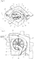
Fig. 3 shows a perspective view of a medicine reserving unit and a medicine dispensing unit depicted inFig. 2 . -
Fig. 4 shows a perspective view of a state in which a reserving container of a medicine reserving unit is removed fromFig. 3 . -
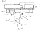
Fig. 5 shows a perspective view of a perspective view of a medicine dispensing unit depicted inFig. 2 . -
Fig. 6 shows a plane view ofFig. 5 . -
Fig. 7 shows an exploded perspective view ofFig. 5 . -
Fig. 8 shows a plane cross sectional view ofFig. 5 . -
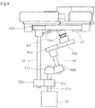
Fig. 9 shows a cross sectional view of an outline of a medicine dispensing unit of another embodiment of the present invention. - Hereunder, embodiments of the present invention will be described according to appended drawings. Now, descriptions hereinafter shall essentially be mere examples and shall not intend to limit the present invention, applied objects thereof or use applications thereof.
-
Fig. 1 shows a perspective view of a medicine packaging apparatus of the present invention. The medicine packaging apparatus comprises an automatic medicine supplying unit 1, a hand feed medicine supplying unit 2, amedicine packaging unit 3, and controller unit 4 and the like. In the automatic medicine supplying unit 1, amedicine cassette 5 is set detachably to each of cassette attaching parts (not shown) which are arranged as a matrix form with a plurality of columns along a width direction and a plurality of stages along a height direction. - The
medicine cassette 5 comprises, as shown inFig. 2 , amedicine reserving unit 6 and a medicine dispensingunit 7. - The
medicine reserving unit 6 is constructed by disposing a supplying rotator 9 in a reservingcontainer 8. In the reservingcontainer 8, a plurality ofmedicines 10 of the same kind (e.g. tablet or capsule) are retained and are supplied timely to themedicine dispensing unit 7. - The reserving
container 8, as shown inFig. 3 , comprises a surroundingwall 11 which has an almost trapezoid shape in a top view. Aguide wall 12 extending downwardly and slantingly is formed on one inner face of a side wall which constructs the surroundingwall 11. Themedicines 10 may be supplied using thisguide wall 12. Theguide wall 12 allows the suppliedmedicines 10 to move smoothly toward a bottom plane side and prevents themedicines 10 from being damaged by impacting the bottom plane side strongly. At a lower side below a region to which theguide wall 12 is formed, asupply port 13 is formed. Thesupply port 13 may be capable of being opened and closed by ashutter 14 which constructs a shutter member of the present invention. - The
shutter 14 may preferably be configured to automatically close when themedicine cassette 5 is detached from the cassette attaching part. For example, thesupply port 13 may be closed by theshutter 14 biased by a springs etc. and a contact portion is disposed to the cassette attaching part such that a part of theshutter 14 may contact to the contact portion so as to open thesupply port 13. - An upper opening of the reserving
container 8, as shown inFig. 2 , is closed by a detachably attachedcover body 15. At a center region of a bottom plane of the reservingcontainer 8, anopening 16 is formed to dispose the supplying rotator 9 therein. - The supplying rotator 9 has a circular shape and comprises an outer
peripheral gear 17 as shown inFig. 4 . A plurality ofridges 18 extend radially outwardly from a rotation center on an upper face. - The outer
peripheral gear 17 meshes with afirst gear 19 and asecond gear 20 sequentially and thesecond gear 20 is integrated to a rotation axis of afirst motor 21. Thereby, driving force of thefirst motor 21 may be transferred to the supplying rotator 9 through thesecond gear 20 and thefirst gear 19. Thefirst motor 21 may be capable of rotating positively and negatively. When the supplying rotator 9 rotates positively, the suppliedmedicines 10 are transferred to thesupply port 13. - Returning to
Fig. 4 , theridges 18 extend outwardly and evenly from the rotation axis to a radially outward peripheral side, and in detailed description extend curvedly with gradual displacements toward an upstream side in a rotational direction. - The
medicine dispensing unit 7, as shown fromFig. 5 to Fig. 7 , is the one to which a supportingmember 23 is fixed in a supportingcontainer 22 and afirst rotator 24, asecond rotator 25, aheight regulation member 26, awidth regulation member 27, and aguide member 28 are attached thereto. - The supporting
container 22 is constructed with a surrounding side wall and a bottom wall and each of the supportingmember 23, theheight regulation member 26 and thewidth regulation member 27 may be fixed by screwing thereto. By cutting out a part of the side wall, adischarge port 29 for themedicines 10 is formed. Themedicines 10 discharged from thedischarge port 29, as shown inFig. 3 , may be countably detected by asensor 30. As shown inFig. 7 , arectangular protrusion part 31 with a slant top face is formed at the bottom wall and acylinder part 32 is formed at a center thereof for rotatably supporting thefirst rotator 24. Around therectangular protrusion part 31, anarch part 33 protrudes in the condition in which a part of a cylinder shape about a center axis of thecylinder part 32 is cut off. An inner face of thearch part 33 and the slant upper face of thefirst rotator 24 construct a reserving concave part 34 (seeFig. 5 ). Aring part 35 is formed around thearch part 33. On thering part 35, thesecond rotator 25 is mounted. Driving force of athird motor 45 may be transferred to thesecond rotator part 25 from adriving gear 46 which is mentioned below through acommunication opening 36 formed by cutting off a part of the reservingconcave part 34. - The supporting
member 23 is disposed in the concave of the supportingcontainer 22 and is fixed by screwing from a lower face side. A part of the supportingmember 23 is constructed with aprotrusion part 37. An inner face of theprotrusion part 37 constructs a part of an inner face surrounding an outer peripheral part of thesecond rotator 25. Theguide member 28 may be fixed by screwing on an upper face of theprotrusion part 37. An end face of theprotrusion part 37 and thewidth regulation member 27 disposed oppositely forms a discharge passage 38 (seeFig. 5 ) therebetween. - The
first rotator 24 has a circular plate shape likely to the abovementioned supplying rotator 9 and on an upper face, i.e. a circular face thereof, a plurality ofprotrusions 39 extend radially from a rotation center (herein, 8 ridges with 45 degrees spacing are formed). Thefirst rotator 24 is disposed such that a rotation axis thereof is slant to a vertical direction and the upper face is slanted to a horizontal plane (a slant angle in the present embodiment is 18 degrees). - At a lower end of the rotation axis of the
first rotator 24, as shown inFig. 8 , a followinggear 40 is integrated. Adriving gear 42, which is integrated to a rotation axis of the second motor 41, meshes with the followinggear 40. Thereby, the driving force of the second motor 41 may be transferred to thefirst rotator 24 through thedriving gear 42 and the followinggear 40. - The
second rotator 25 is, as shown inFig. 7 , a planar ring plate which is disposed at the outer periphery of thefirst rotator 24. Thesecond rotator 25 is disposed such that the upper face i.e. the ring face, is disposed so as to be positioned over a horizontal face. Besides, thecylinder part 43 is formed at a lower face side of thesecond rotator 25 and a followinggear 44 is formed at an outer peripheral face thereof. Adriving gear 46, as shown inFig. 8 , which is integrated to a rotation axis of thethird motor 45, meshes with the followinggear 44. Thereby, the driving force of thethird motor 45 may be transferred to thesecond rotator 25 through thedriving gear 46 and the followinggear 44. - The
height regulation member 26 is shaped generally to a rectangular solid and provides a space between a bottom face thereof and thesecond rotator 25 when fixed by screwing to a side wall of the supportingcontainer 22. The space may be adjusted by changing a screwing position for fixing so as to allow only onemedicine 10 to pass through. - The
width regulation member 27 comprises acurved surface 47. Thewidth regulation member 27 is fixed by screwing to the side wall of the supportingcontainer 22 and is disposed so as to extend inwardly beyond the outer periphery of thesecond rotator 25 for regulating an exposed width size of an upper face of thesecond rotator 25 so that only onemedicine 10 may be carried by thesecond rotator 25. The exposed width size may be adjusted by changing a screwing position for fixing. - The
guide member 28 is constructed by asupport member 48 and aguide chip 49. Thesupport member 48 is formed to about an "L" letter shape from a planar plate and a through hole for fixing to thesupport member 23 by screwing is formed at one end side. At an opposite end side of thesupport member 48, the strip shapedguide chip 49 is fixed at a right angled direction against the upper face of thefirst rotator 24 in the condition out of contact. For theguide chip 49, a material having flexibility as well as an excellent anti-abrasion property such as a silicone rubber may be used. - As shown in
Fig. 6 , theguide chip 49 curves gradually to a downstream side of the rotational direction of thefirst rotator 24 against a radial direction to which the opposite end of the supportingmember 48 extends (inFig. 6 , shown by two dotted line). Thereby, the guide face, which swells out to the outer radial side of thefirst rotator 24, may be formed. When the force larger than that of required is exerted from the contactingmedicine 10 due to the rotation of thefirst rotator 24, themedicine 10 may be moved to an outer radial side by an elastic deformation thereof. - A tip position of the
guide chip 49 reaches adjacent to an inner peripheral edge of thesecond rotator 25 and is located at a shifted position toward the rotational direction from the position where a stepwise difference between the upper face of thefirst rotator 24 and the upper face of thesecond rotator 25 becomes almost zero (inFig. 6 , though a pressured contacting state of themedicine 10 to theguide chip 49 is not illustrated, theguide chip 49 will be curved by the pressurized contact of themedicine 10.). Since the tip position of theguide chip 49 is set as described above, theguide chip 49 does not hinder the rotational movement of thesecond rotator 25 and themedicine 10 can certainly be moved onto thesecond rotator 25 from thefirst rotator 24. - In the
medicine dispensing unit 7 of the above construction, the tip of theguide chip 49 of theguide member 28 is located at the position where the tip is rotated at about 40 degrees - about 45 degrees from a referenced position at which the stepwise difference between the slantfirst rotator 24 and thesecond rotator 25 becomes zero. Besides, theheight regulation member 26 is disposed at about 90 degrees rotated position from the referenced position such that the height size of themedicine 10 may be regulated. Furthermore, beyond theheight regulation member 26, thewidth regulation member 27 is positioned at about 180 degrees rotated position from the referenced position. - The controller unit 4 executes motion control for the
first motor 21, the second motor 41, and thethird motor 45 on the basis of sensor signals of thesensor 30 as well as formulation data from a server (not shown) to carry out the dispensing process as described hereunder. - Next, a motion of the
medicine cassette 5 having the above construction will be described. When themedicines 10 retained in themedicine cassette 5 are dispensed, the first rotator24 and thesecond rotator 25 are rotated. Thereby, themedicines 10 on thefirst rotator 24 moves to the circumference direction and will contact with theguide chip 49 of theguide member 28. Themedicines 10 contacted with theguide chip 40 move to the outer radial side along theguide chip 49. By providing theguide chip 49, smooth movements become possible even if the rotation speed of thefirst rotator 24 is slower than that of the conventional one and thus themedicines 10 may not be moved to the outer radial side only by the exerted centrifugal force. - Now, in the case that an outer radial size of the
first rotator 24 is reduced significantly comparing with the conventional one and thefirst rotator 24 is rotated at the similar rotation speed with the conventional one, the centrifugal force exerted to themedicine 10 becomes insufficient. Thus, it becomes necessary to increase the rotation speed of thefirst rotator 24. However, when the rotation speed of thefirst rotator 24 becomes high, slipping contact speeds between themedicines 10 and thefirst rotator 24 become increased and conditions in which themedicines 10 are easy to be damaged are created. According to the present embodiment, by disposing theguide member 28, the rotation speed of thefist rotator 24 may be lowered than the conventional one so that themedicines 10 may be transferred onto thesecond rotator 25 certainly while reducing the damage of themedicines 10 sufficiently. Here, the rotation speed of thefirst rotator 24 is set to be the same with that of thesecond rotator 25. That is to say, the speed may be adjusted suitable for dispensing themedicines 10 certainly one by one. Besides, theguide chip 49 is constructed using the material having elasticity. The positions of aheight regulation body 26 and awidth regulation body 27 are adjustable in response to sizes of the medicines as dispensing objects. In addition, the spacing between the tip of the guide chip 49 (an end of the outer radial direction) and the inner circumference face of the supportingmember 23 through which the medicines pass, due to an ability of the elastic deformation of theguide chip 49, changes depending on the sizes of the medicines as dispensing objects. Thus, according to themedicine dispensing unit 7 of the present embodiment medicines having various sizes may be dispensed. Themedicines 10 as the dispensing objects have different characters in sizes, forms, and weights. Therefore, if theguide chip 49 is formed with a rigid body, it may be suspicious to blockages of themedicines 10 when themedicines 10 move along theguide chip 49. In this instance, since theguide chip 49 may change the deformation amounts depending on the difference of the characters, particularly in differences of the sizes of themedicines 10, a distance to the inner circumference face formed by the supportingmember 23 may be changed to appropriate values. As the result, theguide chip 49 may recover the shape prior to the blockage of themedicines 10 so that the blockage state may be cleared or the blockage may not occur. Furthermore, if plural medicines are set about passing through the space between the tip of theguide chip 49 and the supportingmember 23 at the same time, theguide chip 49 may be deformed largely and recover the shape thereof when it bends beyond certain dimensions. As the result, theguide chip 49 may push back a plurality of medicines or depending on cases, theguide chip 49 flicks off the medicines toward the upstream side in the rotational direction of thefirst rotator 24. Thus, the blockage of the medicines becomes harder between the tip of theguide chip 49 and the inner circumference face of the supportingmember 23 and it may be suppressed that a plurality of medicines pass through at the same time between the tip of theguide chip 49 and the inner circumference face of the supportingmember 23. - The
medicines 10 after moved to the outer radial side are transferred to thesecond rotator 25 from thefirst rotator 24. Themedicines 10 after transferred to thesecond rotator 25, according to the rotation of thesecond rotator 25, first themedicines 10 overlapped more than 2 layers or stood vertically are returned inwardly by theheight regulation member 26. Themedicines 10 after passed through theheight regulation member 26 but oversized beyond a predetermined width size (for example, medicines placed 2 lines side by side, and the like) are returned inwardly by thewidth regulation member 27. - As described above, the only one
medicine 10 after passing regulated allowable regions for passing through by theheight regulation member 26 and thewidth regulation member 27 may be dispensed from thedischarge port 29. Here, when the dispensedmedicine 10 is detected by thesensor 30, the rotations of thefirst rotator 24 and thesecond rotator 25 are terminated. Thereby, onemedicine 10 may be dispensed certainly. Then, the rotations of thefirst rotator 24 and thesecond rotator 25 will be restarted again. The termination and restart will be repeated each time onemedicine 10 is detected by thesensor 30. The dispensing process will be terminated when predetermined numbers of themedicines 10 have been dispensed. - Meanwhile, a sensor (not shown) detects whether the dispensed
medicine 10 from the reservingconcave part 34 of themedicine dispensing unit 7 is positioned at a particular position or not (for example, on the second rotator 25) and if determination that the medicine is not positioned at the particular position, the rotation of the supplying rotator 9 may be started. Furthermore, by detecting that the medicine is positioned on the particular position, the supplying rotator 9 may be terminated. Alternatively, when amounts of themedicines 10 to be dispensed run up to predetermined given amounts, the determination may be made that the supply of themedicines 10 is necessary and then the supplying rotator 9 may be rotated. The rotation of the supplying rotator 9 may be performed for predetermined time duration on the basis of relations between the time duration determined by experiments and the amounts of themedicines 10 allowed to be supplied. In summary, the medicines may be supplied on the basis of supply conditions of themedicines 10 in the medicine dispensing unit 7 (the former predicts whether the supply condition permits the dispensation or not depending on presence or absence of themedicines 10 at the particular position and the latter calculates the amounts ofmedicines 10 in themedicine dispensing unit 7 from practically dispensed amounts and specifies the supply condition precisely.). - Here, using a conventional medicine cassette 5 (comparative examples 1, 2), a
medicine cassette 5 of the above embodiment without the guide member 28 (comparative example 3) and with the guide member 28 (example 1), comparing experiments were conducted. In the comparative experiment 1, the outer diameter size of thefirst rotator 24 was set to be 160 mm and the slant angle of thefirst rotator 24 was set to be 13 degrees against the horizontal plane. In the comparative example 2, the outer diameter size of thefirst rotator 24 was set to be 140 mm and the slant angle of thefirst rotator 24 was set to be 18 degrees against the horizontal plane. In the comparative example 3 and the example 1, the outer diameter size of thefirst rotator 24 was set to be 40 mm and the slant angle of thefirst rotator 24 was set to be 13 degrees against the horizontal plane. Tablets having a diameter of 10 mm were dispensed under the conditions listed in Table 1.[Table 1] Comparative Example 1 Comparative Example 2 Comparative Example 3 Example 1 second outer rotator radial size (mm) 160.5 120 40 40 second slant rotator angle (° ) 18 18 13 13 second rotational rotator speed (rpm) 110 157 224 7 - As the results of the comparative experiments, as shown in Table 1, the minimal rotation speeds of the
first rotator 24 required for dispensing the tablets to the second rotator were to be 110 rpm in the comparative example 1; to be 157 rpm in the comparative example 2; and to be 224 rpm in the comparative example 3, respectively. In contrast to the above, the example 1 could transfer the tablets at 7 rpm. - The rotation speed of the
second rotator 25 suitable for dispensing themedicines 10 certainly one by one was to be 7-14 rpm. Therefore, the rotation speed of thefirst rotator 24 may be set to a similar speed (for example, the identical speed). - As described above, with providing the
guide member 28, themedicines 10 were transferred onto thesecond rotator 25 even though the rotation speed of thefirst rotator 24 was lowered to the similar level as low as thesecond rotator 25. Therefore, it was made possible to prevent themedicines 10 from being damaged due to the reduced impact force exerted from thefirst rotator 24. Besides, the first rotator and thesecond rotator 25 were terminated each time onemedicine 10 was dispensed. Therefore, themedicines 10 may not be erroneously dispensed over the necessities because the movement speeds of themedicines 10 along the circumference direction are increased. - In addition, the present invention shall not be limited to the construction described the above embodiments and there may be various modifications.
- For example, in the above embodiments, the
first rotator 24 and thesecond rotator 25 are rotated by separated motors each other, however, it may be possible to rotate using the same motor. For example, as shown inFig. 9 , aspur gear 24b may be integrated to therotation axis 24a of thefirst rotator 24 being slant to the horizontal plane. Thespur gear 24b meshes with aspur gear 50a integrated to arotation axis 50 at one end side. Abevel gear 50b integrated to arotation axis 50 at the opposite end side meshes with a bevel gear 51b integrated to arotation axis 51a of amotor 51. The followinggear 44 of thesecond rotator 25 meshes with aspur gear 52a integrated to arotation axis 52 at one end side. Aspur gear 52b integrated to therotation axis 52 at the opposite end side meshes with aspur gear 51c integrated to therotation axis 51a of themotor 51. Thereby, when themotor 51 is actuated, thefirst rotator 24 and thesecond rotator 25 rotate synchronously through each of the gears. - Alternatively, in the above embodiments, the
supply port 13 may be closed when themedicine cassette 5 is detached from the cassette attaching part; however, themedicine dispensing part 7 may be constructed detachably from themedicine cassette 5 andsupply port 13 may be closed by theshutter 14 when themedicine dispensing unit 7 is detached therefrom. - 1-automatic medicine suppling unit 2-hand feed medicine supplying unit 3-medicine packaging unit 4-controller unit 4 5-medicine cassette 6- medicine reserving unit 7-medicine dispensing unit 8- reserving container 9- supplying rotator 10- medicine 11-surrounding wall 12- guide wall 13- supply port (feed port) 14- shutter 15- cover body 16-opening 17-outer peripheral gear 18-ridges 19-first gear 20-second gear 21- first motor 22- supporting container 23- supporting member 24- first rotator 25- second rotator 26- height regulation member 27- width regulation member 28- guide member 29- discharge port 30- sensor 31-rectangular protrusion 32- cylinder member 33- arch part 34- reserving concave part 35- ring part 36-communication opening 37- protrusion part 38- discharge passage 39- protrusions 40- following gear 41- second motor 42-driving gear 43- cylinder part 44- following gear 45- third motor 46- driving gear 47-curved surface 48- support member 49- guide chip 50- rotation axis 51- motor (driver means) 52- rotation axis
Claims (8)
- A medicine cassette (5) comprising a medicine dispensing unit (7) for dispensing a medicine retained, the medicine dispensing unit (7) comprising:a first rotator (24) having a circular face rotatably disposed at a slant state to a horizontal plane;a second rotator (25) having a ring face rotatably disposed over the horizontal plane at an outer peripheral side of the first rotator (24), characterised in that it further comprises a guide member (28) having a guide face, the guide face being disposed above the circular face of the first rotator while extending radially with respect to the circular face, being positioned at a downstream side in a rotational direction of the first rotator (24) towards a periphery in a radial direction, and being capable of contacting with the medicine placed on the first rotator (24) due to rotation of the first rotator (24), whereby in the guide member (28), at least a part including the guide face to be contacted with the medicine is capable of deforming elastically so as to modify a positional relationship to the second rotator (25) depending on a size of the medicine.
- The medicine cassette of claim 1, further comprising a second motor (41) having a rotation axis integrated with a driving gear (42) engaging with a following gear (40) integrated at a lower end of a rotation axis of the first rotator (24), and wherein the second motor (41) is configured to rotate the first rotator (24) at a rate being insufficient to move the medicine to an outer peripheral side only by a centrifugal force, but sufficient to move the medicine to the outer peripheral side along the guide member (28).
- The medicine cassette of claim 2, wherein the second motor (41) is configured to stop the first rotator (24) every time one medicine is dispensed.
- The medicine cassette of any one of claims 1 to 3, wherein the first rotator (24) and the second rotator (25) are rotated by an identical driver means.
- The medicine cassette of claims 1, further comprising a motor (51) provided with a rotation axis (51a), whereby
the first rotator (24) is provided with a rotation axis (24a) extending obliquely downwards and having a spur gear (24b) at its lower end, said spur gear (24b) engaging with a spur gear (50a) integrated to one end of a rotation axis (50), while its opposite end is having a bevel gear (50b) engaging in turn with a bevel gear (51b) integrated to a rotation axis (51a) of the motor (51),
the second rotator (25) is provided with a following gear (44) engaging with a spur gear (52a) integrated to one end side of a rotation axis (52), which on its opposite end side the rotation axis (52) has a spur gear (52b) engaging with a spur gear (51c) integrated to the rotation axis (51a) of the motor (51),
the motor (51) is configured to stop the first rotator (24) and the second rotator (25) every time one medicine is dispensed. - The medicine cassette of any one of claims 1 to 5 further comprising a medicine supplying unit for supplying the medicine to the medicine dispensing unit (7), the medicine supplying unit being capable of supplying the medicine depending on replenishment status of the medicine at the medicine dispensing unit (7).
- The medicine cassette of claim 6, wherein the medicine supplying unit is detachable from the medicine dispensing unit (7) and comprises a supply port (13) for supplying the medicine to the medicine dispensing unit (7) and a shutter member (14) for closing the supply port (13) when the medicine dispensing unit (7) is detached from the medicine supplying unit.
- The medicine cassette of claim 7, wherein the medicine cassette (5) is attachable to and detachable from a cassette attaching part, and the shutter member (14) closes the supply port (13) of the medicine dispensing unit (7) when the medicine cassette (5) is detached from the cassette attaching part.
Applications Claiming Priority (2)
| Application Number | Priority Date | Filing Date | Title |
|---|---|---|---|
| JP2014150196 | 2014-07-23 | ||
| PCT/JP2015/070750 WO2016013553A1 (en) | 2014-07-23 | 2015-07-21 | Medicine cassette |
Publications (3)
| Publication Number | Publication Date |
|---|---|
| EP3173060A1 EP3173060A1 (en) | 2017-05-31 |
| EP3173060A4 EP3173060A4 (en) | 2018-03-21 |
| EP3173060B1 true EP3173060B1 (en) | 2019-06-12 |
Family
ID=55163077
Family Applications (1)
| Application Number | Title | Priority Date | Filing Date |
|---|---|---|---|
| EP15825431.8A Active EP3173060B1 (en) | 2014-07-23 | 2015-07-21 | Medicine cassette |
Country Status (6)
| Country | Link |
|---|---|
| US (1) | US9877896B2 (en) |
| EP (1) | EP3173060B1 (en) |
| JP (1) | JP5867666B1 (en) |
| KR (1) | KR102360460B1 (en) |
| CN (1) | CN106535859B (en) |
| WO (1) | WO2016013553A1 (en) |
Families Citing this family (13)
| Publication number | Priority date | Publication date | Assignee | Title |
|---|---|---|---|---|
| JP6172489B1 (en) | 2015-11-30 | 2017-08-02 | 株式会社湯山製作所 | Drug cassette, drug dispensing device, and drug packaging device |
| JP6736064B2 (en) * | 2017-01-04 | 2020-08-05 | 株式会社トーショー | Drug feeder |
| CN107380943A (en) * | 2017-07-26 | 2017-11-24 | 宜兴新高合金制品有限公司 | A kind of mass spiral vibration conveying device |
| CA3072585A1 (en) * | 2017-08-15 | 2019-02-21 | Yuyama Mfg. Co., Ltd. | Tablet guiding path adjusting apparatus for tablet cassette |
| KR101880924B1 (en) * | 2017-09-26 | 2018-07-23 | (주)제이브이엠 | Medicine cassette and automatic medicine packing machine therewith |
| CN107898315B (en) * | 2017-11-21 | 2020-09-04 | 宿迁市宿城区人民医院 | Brewing device and method for traditional Chinese medicine conditioning medicinal tea |
| CN108963852B (en) * | 2018-07-23 | 2020-06-02 | 冯航军 | Electric power overhaul tool distribution device capable of manually changing voltage regulation stabilizing piece of elastic element |
| JP7233076B2 (en) * | 2018-09-21 | 2023-03-06 | 株式会社タカゾノ | drug supply device |
| JP2020124327A (en) * | 2019-02-04 | 2020-08-20 | 株式会社タカゾノ | Medicine supplying device |
| CN110884777B (en) * | 2019-10-18 | 2021-08-27 | 福建师范大学 | Medicine bottle capable of simply and conveniently distributing medicine |
| JP7337383B2 (en) * | 2020-01-29 | 2023-09-04 | 株式会社トーショー | drug feeder |
| CN111824475B (en) * | 2020-07-17 | 2021-07-23 | 郑州轻工业大学 | Particle size adjustable tablet medicine pendulum medicine device |
| CN113479954B (en) * | 2021-08-10 | 2022-01-25 | 宿迁凯达环保设备制造有限公司 | Sewage treatment device of environmental protection |
Family Cites Families (13)
| Publication number | Priority date | Publication date | Assignee | Title |
|---|---|---|---|---|
| JP2541997B2 (en) | 1987-08-12 | 1996-10-09 | ディーエスエム ナムローゼ フェンノートシャップ | Curing method with active energy rays |
| JPH0651529B2 (en) * | 1989-11-01 | 1994-07-06 | 株式会社エフアイテイ | Feeder |
| JP2000203525A (en) * | 1999-01-11 | 2000-07-25 | Dainippon Printing Co Ltd | Tablet feed hopper |
| JP2002347921A (en) | 2001-05-25 | 2002-12-04 | Ntn Corp | Component feeder |
| JP2008127133A (en) * | 2006-11-17 | 2008-06-05 | Nakamichi:Kk | Part feeder |
| JP3148073U (en) * | 2008-11-16 | 2009-01-29 | 木下精工有限会社 | Parts supply device |
| TWI585017B (en) * | 2009-08-28 | 2017-06-01 | Yuyama Manufacturing Co Ltd | A medicine discharge device, a hopper, and a method for manufacturing the same |
| KR101820799B1 (en) * | 2010-12-09 | 2018-01-22 | 가부시키가이샤 유야마 세이사쿠쇼 | Drug dispenser and drug counter |
| US9155681B2 (en) * | 2011-01-20 | 2015-10-13 | Yuyama Mfg. Co., Ltd. | Medicine feeding device and a medicine counting device using the medicine feeding device |
| US9242785B2 (en) * | 2011-09-06 | 2016-01-26 | Yuyama Mfg. Co., Ltd. | Medicine cassette and medicine feeding apparatus |
| WO2013141130A1 (en) * | 2012-03-21 | 2013-09-26 | 株式会社湯山製作所 | Drug-supplying device and drug-counting device |
| KR20130118838A (en) | 2013-08-02 | 2013-10-30 | 임도현 | Telescope sight method for zeroing |
| WO2015052794A1 (en) * | 2013-10-09 | 2015-04-16 | 株式会社タカゾノテクノロジー | Medicine filling device |
-
2015
- 2015-07-21 KR KR1020177001531A patent/KR102360460B1/en active IP Right Grant
- 2015-07-21 WO PCT/JP2015/070750 patent/WO2016013553A1/en active Application Filing
- 2015-07-21 EP EP15825431.8A patent/EP3173060B1/en active Active
- 2015-07-21 US US15/328,431 patent/US9877896B2/en active Active
- 2015-07-21 CN CN201580038136.4A patent/CN106535859B/en active Active
- 2015-07-21 JP JP2015548097A patent/JP5867666B1/en active Active
Non-Patent Citations (1)
| Title |
|---|
| None * |
Also Published As
| Publication number | Publication date |
|---|---|
| KR102360460B1 (en) | 2022-02-10 |
| CN106535859B (en) | 2019-06-14 |
| JP5867666B1 (en) | 2016-02-24 |
| WO2016013553A1 (en) | 2016-01-28 |
| EP3173060A1 (en) | 2017-05-31 |
| EP3173060A4 (en) | 2018-03-21 |
| US9877896B2 (en) | 2018-01-30 |
| CN106535859A (en) | 2017-03-22 |
| US20170216150A1 (en) | 2017-08-03 |
| KR20170034383A (en) | 2017-03-28 |
| JPWO2016013553A1 (en) | 2017-04-27 |
Similar Documents
| Publication | Publication Date | Title |
|---|---|---|
| EP3173060B1 (en) | Medicine cassette | |
| JP6135742B2 (en) | Drug discharge device | |
| US7669733B2 (en) | Cassette device for automatic medicine packaging apparatus | |
| US9233789B2 (en) | Medicine-supplying device and medicine-counting device | |
| US8281955B2 (en) | Passive device for staging and dispensing objects | |
| US8244398B2 (en) | Device for selectively presenting objects | |
| CN108119345A (en) | Peristaltic-type pump arrangement | |
| KR200459198Y1 (en) | Rotary type tablet dispenser | |
| JP2023052649A (en) | Medicine packaging apparatus | |
| KR100623387B1 (en) | Dispensing apparatus for powder medicine | |
| CN114348363B (en) | But contain top groove's granule racking machine for pharmacy | |
| US20220332493A1 (en) | Vacuum-based retrieving and dispensing | |
| JP4837641B2 (en) | Powder distribution device | |
| CA3076226A1 (en) | Pill dispensing canister | |
| JP7337382B2 (en) | drug feeder | |
| JP4852114B2 (en) | Powder distribution device and packing machine | |
| JP7337383B2 (en) | drug feeder | |
| CN115966486A (en) | Substrate processing apparatus and substrate processing method | |
| JP7325756B2 (en) | drug feeder | |
| JP7160290B2 (en) | CENTRIFUGE AND SUSPENSION PREPARATION METHOD USING THE SAME | |
| KR100613020B1 (en) | Feeder for powder medicine | |
| JP6370678B2 (en) | Substrate liquid processing equipment | |
| KR20220090958A (en) | Pharmaceutical cartridge drying device | |
| KR20170027972A (en) | Switchgear and pharmaceutical preparation system comprising the switchgear |
Legal Events
| Date | Code | Title | Description |
|---|---|---|---|
| STAA | Information on the status of an ep patent application or granted ep patent |
Free format text: STATUS: THE INTERNATIONAL PUBLICATION HAS BEEN MADE |
|
| PUAI | Public reference made under article 153(3) epc to a published international application that has entered the european phase |
Free format text: ORIGINAL CODE: 0009012 |
|
| STAA | Information on the status of an ep patent application or granted ep patent |
Free format text: STATUS: REQUEST FOR EXAMINATION WAS MADE |
|
| 17P | Request for examination filed |
Effective date: 20170221 |
|
| AK | Designated contracting states |
Kind code of ref document: A1 Designated state(s): AL AT BE BG CH CY CZ DE DK EE ES FI FR GB GR HR HU IE IS IT LI LT LU LV MC MK MT NL NO PL PT RO RS SE SI SK SM TR |
|
| AX | Request for extension of the european patent |
Extension state: BA ME |
|
| DAV | Request for validation of the european patent (deleted) | ||
| DAX | Request for extension of the european patent (deleted) | ||
| A4 | Supplementary search report drawn up and despatched |
Effective date: 20180216 |
|
| RIC1 | Information provided on ipc code assigned before grant |
Ipc: A61J 3/00 20060101AFI20180212BHEP Ipc: B65B 1/30 20060101ALI20180212BHEP Ipc: B65B 37/08 20060101ALI20180212BHEP |
|
| STAA | Information on the status of an ep patent application or granted ep patent |
Free format text: STATUS: EXAMINATION IS IN PROGRESS |
|
| 17Q | First examination report despatched |
Effective date: 20180827 |
|
| GRAP | Despatch of communication of intention to grant a patent |
Free format text: ORIGINAL CODE: EPIDOSNIGR1 |
|
| STAA | Information on the status of an ep patent application or granted ep patent |
Free format text: STATUS: GRANT OF PATENT IS INTENDED |
|
| INTG | Intention to grant announced |
Effective date: 20190211 |
|
| GRAJ | Information related to disapproval of communication of intention to grant by the applicant or resumption of examination proceedings by the epo deleted |
Free format text: ORIGINAL CODE: EPIDOSDIGR1 |
|
| STAA | Information on the status of an ep patent application or granted ep patent |
Free format text: STATUS: EXAMINATION IS IN PROGRESS |
|
| GRAS | Grant fee paid |
Free format text: ORIGINAL CODE: EPIDOSNIGR3 |
|
| STAA | Information on the status of an ep patent application or granted ep patent |
Free format text: STATUS: GRANT OF PATENT IS INTENDED |
|
| GRAP | Despatch of communication of intention to grant a patent |
Free format text: ORIGINAL CODE: EPIDOSNIGR1 |
|
| INTC | Intention to grant announced (deleted) | ||
| GRAA | (expected) grant |
Free format text: ORIGINAL CODE: 0009210 |
|
| STAA | Information on the status of an ep patent application or granted ep patent |
Free format text: STATUS: THE PATENT HAS BEEN GRANTED |
|
| INTG | Intention to grant announced |
Effective date: 20190424 |
|
| AK | Designated contracting states |
Kind code of ref document: B1 Designated state(s): AL AT BE BG CH CY CZ DE DK EE ES FI FR GB GR HR HU IE IS IT LI LT LU LV MC MK MT NL NO PL PT RO RS SE SI SK SM TR |
|
| REG | Reference to a national code |
Ref country code: GB Ref legal event code: FG4D |
|
| REG | Reference to a national code |
Ref country code: CH Ref legal event code: EP |
|
| REG | Reference to a national code |
Ref country code: AT Ref legal event code: REF Ref document number: 1141650 Country of ref document: AT Kind code of ref document: T Effective date: 20190615 |
|
| REG | Reference to a national code |
Ref country code: DE Ref legal event code: R096 Ref document number: 602015031986 Country of ref document: DE |
|
| REG | Reference to a national code |
Ref country code: IE Ref legal event code: FG4D |
|
| REG | Reference to a national code |
Ref country code: NL Ref legal event code: FP |
|
| REG | Reference to a national code |
Ref country code: LT Ref legal event code: MG4D |
|
| PG25 | Lapsed in a contracting state [announced via postgrant information from national office to epo] |
Ref country code: LT Free format text: LAPSE BECAUSE OF FAILURE TO SUBMIT A TRANSLATION OF THE DESCRIPTION OR TO PAY THE FEE WITHIN THE PRESCRIBED TIME-LIMIT Effective date: 20190612 Ref country code: NO Free format text: LAPSE BECAUSE OF FAILURE TO SUBMIT A TRANSLATION OF THE DESCRIPTION OR TO PAY THE FEE WITHIN THE PRESCRIBED TIME-LIMIT Effective date: 20190912 Ref country code: HR Free format text: LAPSE BECAUSE OF FAILURE TO SUBMIT A TRANSLATION OF THE DESCRIPTION OR TO PAY THE FEE WITHIN THE PRESCRIBED TIME-LIMIT Effective date: 20190612 Ref country code: FI Free format text: LAPSE BECAUSE OF FAILURE TO SUBMIT A TRANSLATION OF THE DESCRIPTION OR TO PAY THE FEE WITHIN THE PRESCRIBED TIME-LIMIT Effective date: 20190612 Ref country code: SE Free format text: LAPSE BECAUSE OF FAILURE TO SUBMIT A TRANSLATION OF THE DESCRIPTION OR TO PAY THE FEE WITHIN THE PRESCRIBED TIME-LIMIT Effective date: 20190612 Ref country code: AL Free format text: LAPSE BECAUSE OF FAILURE TO SUBMIT A TRANSLATION OF THE DESCRIPTION OR TO PAY THE FEE WITHIN THE PRESCRIBED TIME-LIMIT Effective date: 20190612 |
|
| PG25 | Lapsed in a contracting state [announced via postgrant information from national office to epo] |
Ref country code: LV Free format text: LAPSE BECAUSE OF FAILURE TO SUBMIT A TRANSLATION OF THE DESCRIPTION OR TO PAY THE FEE WITHIN THE PRESCRIBED TIME-LIMIT Effective date: 20190612 Ref country code: GR Free format text: LAPSE BECAUSE OF FAILURE TO SUBMIT A TRANSLATION OF THE DESCRIPTION OR TO PAY THE FEE WITHIN THE PRESCRIBED TIME-LIMIT Effective date: 20190913 Ref country code: BG Free format text: LAPSE BECAUSE OF FAILURE TO SUBMIT A TRANSLATION OF THE DESCRIPTION OR TO PAY THE FEE WITHIN THE PRESCRIBED TIME-LIMIT Effective date: 20190912 Ref country code: RS Free format text: LAPSE BECAUSE OF FAILURE TO SUBMIT A TRANSLATION OF THE DESCRIPTION OR TO PAY THE FEE WITHIN THE PRESCRIBED TIME-LIMIT Effective date: 20190612 |
|
| REG | Reference to a national code |
Ref country code: AT Ref legal event code: MK05 Ref document number: 1141650 Country of ref document: AT Kind code of ref document: T Effective date: 20190612 |
|
| PG25 | Lapsed in a contracting state [announced via postgrant information from national office to epo] |
Ref country code: PT Free format text: LAPSE BECAUSE OF FAILURE TO SUBMIT A TRANSLATION OF THE DESCRIPTION OR TO PAY THE FEE WITHIN THE PRESCRIBED TIME-LIMIT Effective date: 20191014 Ref country code: CZ Free format text: LAPSE BECAUSE OF FAILURE TO SUBMIT A TRANSLATION OF THE DESCRIPTION OR TO PAY THE FEE WITHIN THE PRESCRIBED TIME-LIMIT Effective date: 20190612 Ref country code: RO Free format text: LAPSE BECAUSE OF FAILURE TO SUBMIT A TRANSLATION OF THE DESCRIPTION OR TO PAY THE FEE WITHIN THE PRESCRIBED TIME-LIMIT Effective date: 20190612 Ref country code: SK Free format text: LAPSE BECAUSE OF FAILURE TO SUBMIT A TRANSLATION OF THE DESCRIPTION OR TO PAY THE FEE WITHIN THE PRESCRIBED TIME-LIMIT Effective date: 20190612 Ref country code: AT Free format text: LAPSE BECAUSE OF FAILURE TO SUBMIT A TRANSLATION OF THE DESCRIPTION OR TO PAY THE FEE WITHIN THE PRESCRIBED TIME-LIMIT Effective date: 20190612 Ref country code: EE Free format text: LAPSE BECAUSE OF FAILURE TO SUBMIT A TRANSLATION OF THE DESCRIPTION OR TO PAY THE FEE WITHIN THE PRESCRIBED TIME-LIMIT Effective date: 20190612 |
|
| RAP2 | Party data changed (patent owner data changed or rights of a patent transferred) |
Owner name: YUYAMA MFG. CO., LTD. |
|
| PG25 | Lapsed in a contracting state [announced via postgrant information from national office to epo] |
Ref country code: SM Free format text: LAPSE BECAUSE OF FAILURE TO SUBMIT A TRANSLATION OF THE DESCRIPTION OR TO PAY THE FEE WITHIN THE PRESCRIBED TIME-LIMIT Effective date: 20190612 Ref country code: IS Free format text: LAPSE BECAUSE OF FAILURE TO SUBMIT A TRANSLATION OF THE DESCRIPTION OR TO PAY THE FEE WITHIN THE PRESCRIBED TIME-LIMIT Effective date: 20191012 Ref country code: IT Free format text: LAPSE BECAUSE OF FAILURE TO SUBMIT A TRANSLATION OF THE DESCRIPTION OR TO PAY THE FEE WITHIN THE PRESCRIBED TIME-LIMIT Effective date: 20190612 Ref country code: ES Free format text: LAPSE BECAUSE OF FAILURE TO SUBMIT A TRANSLATION OF THE DESCRIPTION OR TO PAY THE FEE WITHIN THE PRESCRIBED TIME-LIMIT Effective date: 20190612 |
|
| REG | Reference to a national code |
Ref country code: CH Ref legal event code: PL |
|
| REG | Reference to a national code |
Ref country code: DE Ref legal event code: R097 Ref document number: 602015031986 Country of ref document: DE |
|
| PG25 | Lapsed in a contracting state [announced via postgrant information from national office to epo] |
Ref country code: MC Free format text: LAPSE BECAUSE OF FAILURE TO SUBMIT A TRANSLATION OF THE DESCRIPTION OR TO PAY THE FEE WITHIN THE PRESCRIBED TIME-LIMIT Effective date: 20190612 Ref country code: TR Free format text: LAPSE BECAUSE OF FAILURE TO SUBMIT A TRANSLATION OF THE DESCRIPTION OR TO PAY THE FEE WITHIN THE PRESCRIBED TIME-LIMIT Effective date: 20190612 |
|
| REG | Reference to a national code |
Ref country code: BE Ref legal event code: MM Effective date: 20190731 |
|
| PLBE | No opposition filed within time limit |
Free format text: ORIGINAL CODE: 0009261 |
|
| STAA | Information on the status of an ep patent application or granted ep patent |
Free format text: STATUS: NO OPPOSITION FILED WITHIN TIME LIMIT |
|
| PG25 | Lapsed in a contracting state [announced via postgrant information from national office to epo] |
Ref country code: PL Free format text: LAPSE BECAUSE OF FAILURE TO SUBMIT A TRANSLATION OF THE DESCRIPTION OR TO PAY THE FEE WITHIN THE PRESCRIBED TIME-LIMIT Effective date: 20190612 Ref country code: DK Free format text: LAPSE BECAUSE OF FAILURE TO SUBMIT A TRANSLATION OF THE DESCRIPTION OR TO PAY THE FEE WITHIN THE PRESCRIBED TIME-LIMIT Effective date: 20190612 |
|
| 26N | No opposition filed |
Effective date: 20200313 |
|
| PG25 | Lapsed in a contracting state [announced via postgrant information from national office to epo] |
Ref country code: LU Free format text: LAPSE BECAUSE OF NON-PAYMENT OF DUE FEES Effective date: 20190721 Ref country code: LI Free format text: LAPSE BECAUSE OF NON-PAYMENT OF DUE FEES Effective date: 20190731 Ref country code: IS Free format text: LAPSE BECAUSE OF FAILURE TO SUBMIT A TRANSLATION OF THE DESCRIPTION OR TO PAY THE FEE WITHIN THE PRESCRIBED TIME-LIMIT Effective date: 20200224 Ref country code: SI Free format text: LAPSE BECAUSE OF FAILURE TO SUBMIT A TRANSLATION OF THE DESCRIPTION OR TO PAY THE FEE WITHIN THE PRESCRIBED TIME-LIMIT Effective date: 20190612 Ref country code: CH Free format text: LAPSE BECAUSE OF NON-PAYMENT OF DUE FEES Effective date: 20190731 Ref country code: BE Free format text: LAPSE BECAUSE OF NON-PAYMENT OF DUE FEES Effective date: 20190731 |
|
| PG2D | Information on lapse in contracting state deleted |
Ref country code: IS |
|
| PG25 | Lapsed in a contracting state [announced via postgrant information from national office to epo] |
Ref country code: IE Free format text: LAPSE BECAUSE OF NON-PAYMENT OF DUE FEES Effective date: 20190721 |
|
| GBPC | Gb: european patent ceased through non-payment of renewal fee |
Effective date: 20190912 |
|
| PG25 | Lapsed in a contracting state [announced via postgrant information from national office to epo] |
Ref country code: GB Free format text: LAPSE BECAUSE OF NON-PAYMENT OF DUE FEES Effective date: 20190912 |
|
| PG25 | Lapsed in a contracting state [announced via postgrant information from national office to epo] |
Ref country code: CY Free format text: LAPSE BECAUSE OF FAILURE TO SUBMIT A TRANSLATION OF THE DESCRIPTION OR TO PAY THE FEE WITHIN THE PRESCRIBED TIME-LIMIT Effective date: 20190612 |
|
| PG25 | Lapsed in a contracting state [announced via postgrant information from national office to epo] |
Ref country code: MT Free format text: LAPSE BECAUSE OF FAILURE TO SUBMIT A TRANSLATION OF THE DESCRIPTION OR TO PAY THE FEE WITHIN THE PRESCRIBED TIME-LIMIT Effective date: 20190612 Ref country code: HU Free format text: LAPSE BECAUSE OF FAILURE TO SUBMIT A TRANSLATION OF THE DESCRIPTION OR TO PAY THE FEE WITHIN THE PRESCRIBED TIME-LIMIT; INVALID AB INITIO Effective date: 20150721 |
|
| PG25 | Lapsed in a contracting state [announced via postgrant information from national office to epo] |
Ref country code: MK Free format text: LAPSE BECAUSE OF FAILURE TO SUBMIT A TRANSLATION OF THE DESCRIPTION OR TO PAY THE FEE WITHIN THE PRESCRIBED TIME-LIMIT Effective date: 20190612 |
|
| PGFP | Annual fee paid to national office [announced via postgrant information from national office to epo] |
Ref country code: NL Payment date: 20230719 Year of fee payment: 9 |
|
| PGFP | Annual fee paid to national office [announced via postgrant information from national office to epo] |
Ref country code: FR Payment date: 20230726 Year of fee payment: 9 Ref country code: DE Payment date: 20230719 Year of fee payment: 9 |