EP3172984B9 - Structure of grip of bag and method for attachment of same - Google Patents
Structure of grip of bag and method for attachment of same Download PDFInfo
- Publication number
- EP3172984B9 EP3172984B9 EP15824933.4A EP15824933A EP3172984B9 EP 3172984 B9 EP3172984 B9 EP 3172984B9 EP 15824933 A EP15824933 A EP 15824933A EP 3172984 B9 EP3172984 B9 EP 3172984B9
- Authority
- EP
- European Patent Office
- Prior art keywords
- region
- hand
- carrying member
- longitudinal edge
- carrying
- Prior art date
- Legal status (The legal status is an assumption and is not a legal conclusion. Google has not performed a legal analysis and makes no representation as to the accuracy of the status listed.)
- Active
Links
- 238000000034 method Methods 0.000 title claims description 15
- 238000009958 sewing Methods 0.000 claims description 45
- 239000000126 substance Substances 0.000 claims description 19
- 230000005291 magnetic effect Effects 0.000 claims description 18
- 230000008878 coupling Effects 0.000 claims description 8
- 238000010168 coupling process Methods 0.000 claims description 8
- 238000005859 coupling reaction Methods 0.000 claims description 8
- 239000004744 fabric Substances 0.000 description 30
- 239000010985 leather Substances 0.000 description 28
- 238000004519 manufacturing process Methods 0.000 description 14
- 238000010586 diagram Methods 0.000 description 4
- 230000002093 peripheral effect Effects 0.000 description 3
- XEEYBQQBJWHFJM-UHFFFAOYSA-N Iron Chemical compound [Fe] XEEYBQQBJWHFJM-UHFFFAOYSA-N 0.000 description 2
- PXHVJJICTQNCMI-UHFFFAOYSA-N Nickel Chemical compound [Ni] PXHVJJICTQNCMI-UHFFFAOYSA-N 0.000 description 2
- 229910000828 alnico Inorganic materials 0.000 description 1
- 239000010941 cobalt Substances 0.000 description 1
- 229910017052 cobalt Inorganic materials 0.000 description 1
- GUTLYIVDDKVIGB-UHFFFAOYSA-N cobalt atom Chemical compound [Co] GUTLYIVDDKVIGB-UHFFFAOYSA-N 0.000 description 1
- 230000000694 effects Effects 0.000 description 1
- 238000005516 engineering process Methods 0.000 description 1
- 230000005294 ferromagnetic effect Effects 0.000 description 1
- 229910052742 iron Inorganic materials 0.000 description 1
- 229910001172 neodymium magnet Inorganic materials 0.000 description 1
- 229910052759 nickel Inorganic materials 0.000 description 1
- 229910000938 samarium–cobalt magnet Inorganic materials 0.000 description 1
- 229910000859 α-Fe Inorganic materials 0.000 description 1
Images


Classifications
-
- A—HUMAN NECESSITIES
- A45—HAND OR TRAVELLING ARTICLES
- A45C—PURSES; LUGGAGE; HAND CARRIED BAGS
- A45C13/00—Details; Accessories
- A45C13/30—Straps; Bands
-
- A—HUMAN NECESSITIES
- A45—HAND OR TRAVELLING ARTICLES
- A45C—PURSES; LUGGAGE; HAND CARRIED BAGS
- A45C13/00—Details; Accessories
- A45C13/10—Arrangement of fasteners
- A45C13/1023—Arrangement of fasteners with elongated profiles fastened by sliders
- A45C13/103—Arrangement of zip-fasteners
-
- A—HUMAN NECESSITIES
- A45—HAND OR TRAVELLING ARTICLES
- A45C—PURSES; LUGGAGE; HAND CARRIED BAGS
- A45C13/00—Details; Accessories
- A45C13/10—Arrangement of fasteners
- A45C13/1069—Arrangement of fasteners magnetic
-
- A—HUMAN NECESSITIES
- A45—HAND OR TRAVELLING ARTICLES
- A45C—PURSES; LUGGAGE; HAND CARRIED BAGS
- A45C13/00—Details; Accessories
- A45C13/26—Special adaptations of handles
-
- A—HUMAN NECESSITIES
- A45—HAND OR TRAVELLING ARTICLES
- A45C—PURSES; LUGGAGE; HAND CARRIED BAGS
- A45C3/00—Flexible luggage; Handbags
- A45C3/06—Ladies' handbags
-
- A—HUMAN NECESSITIES
- A45—HAND OR TRAVELLING ARTICLES
- A45C—PURSES; LUGGAGE; HAND CARRIED BAGS
- A45C13/00—Details; Accessories
- A45C13/30—Straps; Bands
- A45C2013/306—Straps; Bands for attaching auxiliary articles to luggage, e.g. piggyback
Definitions
- the present invention relates to a structure of a hand-carrying portion of a bag such as a handbag, a shoulder bag, and the like, and a method for attaching the same.
- a handle attachment structure disclosed in JP 4430734 B1 is proposed for the hand-carrying portion of the handbag, the shoulder bag, and the like.
- the handle is formed by joining an outer handle section and an inner handle section, a distal end portion of the outer handle section being attached to a surface of a body and a distal end portion of the inner handle section being attached while being sandwiched between the body and an upper gore section, and handle excels in durability so that the bag can be used over many years.
- the handle tends to fall outward, thereby deforming also the body.
- An object of the present invention is to provide a structure of a hand-carrying portion that less tends to fall and is capable of keeping a predetermined shape, and a method for attaching the same.
- the support member has a plurality of band-shaped bodies laminated, with the laminated band-shaped bodies curved in their width to form the overlapping region in an arch shape with a substantially C-shaped cross section. Therefore, the hand-carrying member can be raised upward.
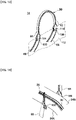
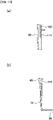
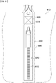
- Fig. 1 is a perspective view of a bag using a structure of a hand-carrying portion of a bag according to one embodiment of the present invention.
- Fig. 2 is a perspective view of a rear side of the bag of Fig. 1 .
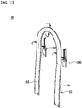
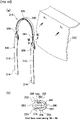
- Fig. 3 is an opposite side view showing the structure of the hand-carrying portion of the bag of Fig. 1 .
- Fig. 4 is a side view showing the structure of the hand-carrying portion of the bag of Fig. 1 .
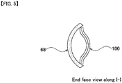
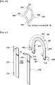
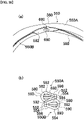
- Fig. 5 is an end face view along I-I of Fig. 4 .
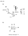
- Fig. 6 is a perspective view showing the structure of the hand-carrying portion of the bag of Fig. 1 .
- Fig. 7 is a cross-sectional view showing the structure of the hand-carrying portion of the bag of Fig. 1 .
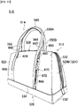
- the structure of the hand-carrying portion of the bag of the present invention can be used to attach a hand-carrying portion 14 to a bag main body 12 of a hand-carrying bag 10 such as an overnight bag, and the like.
- the structure of the hand-carrying portion of the bag of the present invention can also be used in a shoulder bag, and the like, other than the hand-carrying bag.
- the bag main body 12 includes a front body portion 20, a back body portion 22 facing the front body portion 20, a gore portion 24 interposed between the front body portion 20 and the back body portion 22, and a bottom portion 26 arranged at the lower ends of the front body portion 20, the back body portion 22, and the gore portion 24.
- An opening 28 between the front body portion 20 and the back body portion 22 is configured to be opened and closed with a zipper 30 provided at the open edge of the front body portion 20 and an open edge of the back body portion 22.
- the gore portion 24 includes a left side gore portion 24A formed on the left side of the front body portion 20, and a right side gore portion 24B formed on the right side of the front body portion 20.
- the bottom portion 26 is formed by sewing a bottom member 32 overlapped with the outer surfaces of the front body portion 20, the back body portion 22, and the gore portion 24 at the lower end edges of the front body portion 20, the back body portion 22, and the gore portion 24.
- the bottom member 32 is entirely formed to a plate shape, where the peripheral edge thereof is sewed to the front body portion 20, the back body portion 22, and the gore portion 24 at a bottom member joining region 34 having a constant width.
- the structure of the hand-carrying portion attached to the bag main body 12 of the present invention is applied to the hand-carrying portion 14 in which a hand-carrying region A1, which is to be carried by the person's hand, is attached to extend toward the upper side of the front body portion 20 and/or the back body portion 22 on the outer side of the bag main body 12.
- the structure of the hand-carrying portion of the bag according to the present invention is a structure which supports a hand-carrying member 50 attached to the bag main body 12.
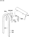
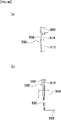
- the hand-carrying member 50 includes a curved region 60, one overlapping region 62 and other overlapping region 64 formed continuously to both ends of the curved region 60, bridging regions (one bridging region 66 and other bridging region 68) formed continuously to the overlapping regions (one overlapping region 62 and other overlapping region 64), and fixing regions (one fixing region 70 and other fixing region 72) formed continuously to the one bridging region 66 and the other bridging region 68 configuring the bridging regions.
- the outer hand-carrying member 50 is curved in a substantially U shape in a front view in the hand-carrying region A1.
- the one bridging region 66 and the one fixing region 70 and the other bridging region 68 and the other fixing region 72 in an extended region which extends from the curved region 60 as divided leftward and rightward are attached with an appropriate space to the outside of the bag main body 12.
- the longitudinal band-shaped hand-carrying member 50 is a linear longitudinal band-shaped body made of leather or fabric, and is formed in an arch shape with a substantially C-shaped cross section by combining both longitudinal edges, that is, one longitudinal edge 52 and other longitudinal edge 54, together.
- the hand-carrying member 50 has the curved region 60, the overlapping regions (one overlapping region 62 and other overlapping region 64), and portions nearby continued to the overlapping regions of the bridging regions (one bridging region 66 and other bridging region 68) formed in an arch shape with a substantially C-shaped cross section.
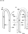
- the hand-carrying member 50 has a support member 100 for each of the one bridging region 66 and the other bridging region 68, the support member 100 intervened between both of the longitudinal edges, that is, between the one longitudinal edge 52 and the other longitudinal edge 54, of the band-shaped body in the one bridging region 66 and the other bridging region 68.
- the support members 100 are formed so as to extend along the one overlapping region 62 and the other overlapping region 64 of the hand-carrying member 50 in order to raise the hand-carrying member 50 upward from the bag main body 12.
- the support member 100 is a linear longitudinal band-shaped body made of leather or fabric, including: an overlapping region 110 having at least its upper portion formed in an arch shape with a substantially C-shaped cross section by combining both longitudinal edges (one longitudinal edge 102 and other longitudinal edge 104) together, a support region 112 extending downward from the overlapping region 110, and a fixing region 114 formed below the support region 112.
- the support member 100 has both longitudinal edges, that is, the one longitudinal edge 102 and the other longitudinal edge 104, of the overlapping region 110 intervened between both longitudinal edges, that is, the one longitudinal edge 52 and the other longitudinal edge 54, of the hand-carrying member 50 formed in an arch shape with a substantially C-shaped cross section.
- the support member 100 is coupled, with the overlapping region 110 of the support member 100 and the overlapping region (one overlapping region 62 and other overlapping region 64) of the hand-carrying member 50 sewed together so that a crest portion 150 of the support member 100 faces a crest portion 90 of the hand-carrying member 50 so as to be positioned oppositely thereto.
- the support member 100 has the support region 112 formed in an arch shape with a substantially C-shaped cross section or a substantially U-shaped cross section at least near the overlapping region 110, and is fixed to the bag main body 12 in the fixing region 114 below the support region 112.
- the hand-carrying member 50 extends downward from the fixing regions 114 of the support members 100 fixed to the bag main body 12, and is fixed to the bag main body 12 in the fixing regions (one fixing region 70 and other fixing region 72) of the hand-carrying member 50.
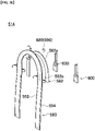
- the support member 100 has a plurality of band-shaped bodies 130 and band-shaped bodies 140 laminated, with the laminated band-shaped bodies 130 and band-shaped bodies 140 curved in their width to form the overlapping region 110 in an arch shape with a substantially C-shaped cross section.
- the band-shaped bodies 130 and band-shaped bodies 140 are formed by folding portions near both band-shaped longitudinal edges made of leather or fabric inward and bonding folded portions together.
- the band-shaped bodies 130 and band-shaped bodies 140 are configured so that the folded portions face each other to be laminated together to form one support member 100.
- the support member 100 has formed therein: a closing portion 156 formed by curving the band-shaped bodies 130 and band-shaped bodies 140 at the center in a width direction with the band-shaped bodies 140 placed inward, closing the one longitudinal edge 102 and the other longitudinal edge 104 together, and sewing the one longitudinal edge 102 and the other longitudinal edge 104 together so that an inner side of the one longitudinal edge 102 and the other longitudinal edge 104 is curved to swell to an outer direction, that is, to a band-shaped bodies 130 side; a swelled portion 152 and a swelled portion 154 continued to the one longitudinal edge 102 and the other longitudinal edge 102; and the crest portion 150 of the support region 112 with the band-shaped bodies 130 and band-shaped bodies 140 curved at the center in the width direction.
- the hand-carrying member 50 is formed by folding a band-shaped body 80 made of leather or fabric so that portions near both longitudinal edges made of band-shaped leather or fabric overlap each other inward, and bonding folded portions together.
- the band-shaped body 80 is configured so that the folded portions face each other to be laminated together to form one hand-carrying member 50.
- the hand-carrying member 50 has formed therein: a closing portion 96 formed by curving the band-shaped body 80 at the center in a width direction with the folded portions placed inward, closing the one longitudinal edge 52 and the other longitudinal edge 54 together, and sewing the one longitudinal edge 52 and the other longitudinal edge 54 together so that an inner side of the one longitudinal edge 52 and the other longitudinal edge 54 is curved to swell to an outer direction, that is, oppositely to the folded portions; a swelled portion 92 and a swelled portion 94 continued to the one longitudinal edge 52 and the other longitudinal edge 54; and the crest portion 90.
- the outer hand-carrying member 50 and the inner support member 100 have different lengths, and the outer hand-carrying member 50 is longer than the inner support member 100.
- the hand-carrying member 50 and the inner support member 100 have a substantially same width.
- the outer hand-carrying member 50 is curved at a portion near the center in the width direction of the band-shaped body 80 in the overlapped regions, that is, the one overlapping region 62 and the other overlapping region 64 of the hand-carrying member 50 and the overlapping regions 110 of the support members 100.
- the one overlapping region 62 and the other overlapping region 64 of the outer hand-carrying member 50 swell toward outside of the bag main body 12.
- the support members 100 are curved at portions near the center in the width direction of the band-shaped bodies 130 in the overlapped regions, that is, the one overlapping region 62 and the other overlapping region 64 of the hand-carrying member 50 and the overlapping regions 110 of the support members 100.
- the overlapping regions 110 of the support members 100 swell toward a bag main body 12 side.
- the closing portion 156 of the band-shaped bodies 130 and band-shaped bodies 140 in the overlapping region 110 is inserted from a space between the one longitudinal edge 52 and the other longitudinal edge 54 in the one overlapping region 62 (and other overlapping region 64) of the hand-carrying member 50 toward the inside of the crest portion 90 of the hand-carrying member 50, and the overlapping region 110 of the support member 100 and the one overlapping region 62 (and other overlapping region 64) of the hand-carrying member 50 are overlapped each other.
- the one longitudinal edge 52 and the other longitudinal edge 54 in the one overlapping region 62 (and other overlapping region 64) of the hand-carrying member 50 reach near the crest portion 150 in the overlapping region 110 of the support member 100.
- a portion near the one longitudinal edge 52 and the other overlapping region 64 of the hand-carrying member 50 and the crest portion 150 of the support member 100 are sewed together along the one longitudinal edge 52 and the other longitudinal edge 54 of the hand-carrying member 50.
- the support region 112 of the support member 100 is located between the overlapping region 110 and the fixing region 114 where the inner support member 100 is attached to the surface of the bag main body 12.
- the support region 112 is formed with the band-shaped bodies 130 and band-shaped bodies 140 curved at the center in the width direction, without the support region 112 portion being sewed.
- the inner support members 100 have the overlapping regions 110 at one end attached to the one overlapping region 62 and the other overlapping region 64 of the hand-carrying member 50, and have the fixing regions 114 at the other end attached to the outer surface of the bag main body 12.
- the inner support members 100 have the overlapping regions 110 at one end sewed to the one overlapping region 62 and the other overlapping region 64 of the hand-carrying member 50 near the left side gore portion 24A (right side gore portion 24B) configuring the gore portion 24 near the opening 28 of the front body portion 20, and also have the fixing regions 114 at the other end sewed to portions near the right side gore portion 24B configuring the gore portion 24 near the opening 28 of the front body portion 20.
- a back surface side of the fixing region 114 is made in contact with and sewed to the outer surface of the bag main body 12.
- the support region 112 which is a non-joining region A4 not in contact with the outer hand-carrying member 50 and the bag main body 12, is formed between the overlapping region 110 and the one overlapping region 62 and the other overlapping region 64 of the outer hand-carrying member 50.
- the inner support member 100 is in a mode of the band-shaped bodies 130 and band-shaped bodies 140 in which the long band-shaped bodies configuring the inner support member 100 are in a flat state on a side near the fixing region 114 in a non-sewing region A2 not sewed to the outer hand-carrying member 50.
- the outer hand-carrying member 50 is curved in a U shape in a front view in the hand-carrying region A1.
- the outer hand-carrying member 50 is attached to the outside of the bag main body 12 with an appropriate space from the outer surface of the bag main body 12 in an extended region extending from the one overlapping region 62 and the other overlapping region 64 overlapped with the inner support members 100 to a bottom direction of the bag main body 12.
- the non-sewing region A2 not sewed to the support member 100 and the bag main body 12 is formed to a position joined to the bag main body 12.
- the outer hand-carrying member 50 is in a mode of a band-shaped body in which the long band-shaped body 80 configuring the outer hand-carrying member 50 is in a flat state at a part (a portion on one end and the other end sides below the one overlapping region 62 and the other overlapping region 64) of the non-sewing region A2 not sewed to the inner support members 100.
- the one fixing region 70 and the other fixing region 72 in the extended region of the outer hand-carrying member 50 are inserted between the bottom member 32 and the bag main body 12 from an edge of a joining region of the bottom member 32 joined to the bag main body 12, and are attached to the outer surface of the bag main body 12 and/or the inner surface of the bag main body 12.
- the outer hand-carrying member 50 has the one fixing region 70 at one end sewed over the front body portion 20 and the bottom member 32 in the bottom member joining region 34 between the bottom member 32 and the front body portion 20 near the left side gore portion 24A.
- the one fixing region 70 at one end of the outer hand-carrying member 50 interposed between the front body portion 20 and the bottom member 32 is attached by sewing.
- the other fixing region 72 at the other end is sewed over the front body portion 20 and the bottom member 32 in the bottom member joining region 34 between the bottom member 32 and the front body portion 20 near the right side gore portion 24B.
- the other fixing region 72 at the other end of the outer hand-carrying member 50 interposed between the front body portion 20 and the bottom member 32 is attached by sewing.
- the outer hand-carrying member 50 has a region configuring the one fixing region 70 and the other fixing region 72 sewed with a back surface side of the long band-shaped member 80 configuring the outer hand-carrying member 50 in a flat state in contact with the outer surface of the bag main body 12.
- a non-joining region A4 not joined to the one fixing region 70 and the other fixing region 72 of the inner hand-carrying member 50 is formed.
- the outer hand-carrying member 50 is in a mode of a band-shaped body in which the long band-shaped body 80 configuring the outer hand-carrying member 50 is in a flat state in the non-joining region A4 not sewed to the inner support members 100 and the bag main body 12.
- the one bridging region 66 and the other bridging region 68 are formed for nipping an article in a space between their inner side and the outer surface of the bag main body 12.
- the longitudinal band-shaped body 80 made of leather or fabric to form the longitudinal band-shaped hand-carrying member 50 is prepared.
- the hand-carrying member 50 is formed by folding the band-shaped body 80 made of leather or fabric so that portions near both longitudinal edges made of band-shaped leather or fabric overlap each other inward, and bonding folded portions together.
- the band-shaped body 80 is configured so that the folded portions face each other to be laminated to form one hand-carrying member 50.
- the band-shaped body 80 is formed in an arch shape with a substantially C-shaped cross section by combining both of the longitudinal edges, that is, the one longitudinal edge 52 and the other longitudinal edge 54, together.
- the hand-carrying member 50 has the curved region 60, the overlapping regions (the one overlapping region 62 and the other overlapping region 64), and portions nearby continued to the overlapping regions of the bridging regions (one bridging region 66 and the other bridging region 68) formed in an arch shape with a substantially C-shaped cross section.
- the curved region 60 and the other overlapping region 64 are sewed together near the one longitudinal edge 52 and the other longitudinal edge 54.
- the hand-carrying member 50 has formed therein: the closing portion 96 formed by curving the band-shaped body 80 at the center in the width direction with the folded portions placed inward, closing the one longitudinal edge 52 and the other longitudinal edge 54 together, and sewing the one longitudinal edge 52 and the other longitudinal edge 54 together so that an inner side of the one longitudinal edge 52 and the other longitudinal edge 54 is curved to swell to an outer direction, that is, oppositely to the folded portions; the swelled portion 92 and the swelled portion 94 continued to the one longitudinal edge 52 and the other longitudinal edge 54; and the crest portion 90 (hand-carrying member forming step).
- the support member 100 is intervened for each of the one bridging region 66 and the other bridging region 68 in each of both longitudinal edges, that is, the one longitudinal edge 52 and the other longitudinal edge 54, of the band-shaped body in the one bridging region 66 and the other bridging region 68 of the hand-carrying member 50.
- the support members 100 are intervened in the one overlapping region 62 and the other overlapping region 64 along the one overlapping region 62 and the other overlapping region 64 of the hand-carrying member 50 in order to raise the hand-carrying member 50 upward from the bag main body 12 (support member intervening step).
- the longitudinal band-shaped bodies 130 and 140 made of leather or fabric forming the support members 100 include the overlapping region 110 having at least an upper portion formed in an arch shape with a substantially C-shaped cross section by combining both longitudinal edges (one longitudinal edge 102 and other longitudinal edge 104) together, the support region 112 extending downward from the overlapping region 110, and the fixing region 114 formed below the support region 112.
- both longitudinal edges that is, the one longitudinal edge 102 and the other longitudinal edge 104, of the overlapping region 110, are intervened in both longitudinal edges, that is, the one longitudinal edge 52 and the other longitudinal edge 54, of the hand-carrying member 50 formed in an arch shape with a substantially C-shaped cross section.
- the overlapping region 110 of the support member 100 and the overlapping region (one overlapping region 62 and other overlapping region 64) of the hand-carrying member 50 are sewed together so that the crest portion 150 of the support member 100 faces the crest portion 90 of the hand-carrying member 50 so as to be positioned oppositely thereto, thereby coupling the support member 100 to the hand-carrying member 50 (support member coupling step).
- the band-shaped bodies 130 and band-shaped bodies 140 are formed by folding portions near both band-shape longitudinal edges made of leather or fabric inward and bonding folded portion together.
- the band-shaped bodies 130 and band-shaped bodies 140 are configured so that the folded portions face each other to be laminated together to form one support member 100.
- the support member 100 has formed therein: the closing portion 156 formed by curving the band-shaped bodies 130 and band-shaped bodies 140 at the center in the width direction with the band-shaped bodies 140 placed inward, closing the one longitudinal edge 102 and the other longitudinal edge 104 together, and sewing the one longitudinal edge 102 and the other longitudinal edge 104 together so that an inner side of the one longitudinal edge 102 and the other longitudinal edge 104 is curved to swell to the outer direction, that is, to the band-shaped bodies 130 side; the swelled portion 152 and the swelled portion 154 continued to the one longitudinal edge 102 and the other longitudinal edge 104; and the crest portion 150 of the support region 112 with the band-shaped bodies 130 and band-shaped bodies 140 curved at the center in the width direction (support member forming step).
- a portion near the one longitudinal edge 52 and the other overlapping region 64 of the hand-carrying member 50 and the crest portion 150 of the support member 100 are sewed together along the one longitudinal edge 52 and the other longitudinal edge 54 of the hand-carrying member 50 to form the sewing portion 160.
- the support member 100 is formed so that the support region 112 has an arch shape with a substantially C-shaped or substantially U-shaped cross section at least near the overlapping region 110, and the fixing region 114 below the support region 112 is fixed to the bag main body 12 (support member fixing step).
- the hand-carrying member 50 extends downward from the fixing region 114 of the support members 100 fixed to the bag main body 12, and is fixed to the bag main body 12 in the fixing regions (one fixing region 70 and other fixing region 72) of the hand-carrying member 50 (hand-carrying member fixing step).
- the support region 112 of the support member 100 is located between the overlapping region 110 and the fixing region 114 where the inner support member 100 is attached to the surface of the bag main body 12.
- the support region 112 is formed with the band-shaped bodies 130 and band-shaped-bodies 140 curved at the center in the width direction, without the support region 112 portion being sewed.
- the overlapping regions 110 at one end of the inner support members 100 are attached to the one overlapping region 62 and the other overlapping region 64 of the hand-carrying members 50, and the fixing regions 114 at the other end are attached to the outer surface of the back main body 12.
- the overlapping regions 110 at one end of the inner support members 100 are sewed to the one overlapping region 62 and the other overlapping region 64 of the hand-carrying member 50 near the left side gore portion 24A (right side gore portion 24B) configuring the gore portion 24 near the opening 28 of the front body portion 20, and also the fixing regions 114 at the other end are sewed to portions near the right side gore portion 24B configuring the gore portion 24 near the opening 28 of the front body portion 20.
- the back surface side of the fixing regions 114 in a flat state of the long band-shaped bodies (band-shaped bodies 130 and band-shaped bodies 140) configuring the inner support member 100 is made in contact with and sewed to the outer surface of the bag main body 12.
- the bag including the structure of the hand-carrying portion 14 of the bag of the present invention can be formed.
- the longitudinal band-shaped hand-carrying member 250 is formed in an arch shape with a substantially C-shaped cross section by combining both longitudinal edges (one longitudinal edge 252 and other longitudinal edge 254) together.
- the hand-carrying member 250 has support members 300 intervened therein for raising the hand-carrying member 250 upward from the bag main body 212.
- the hand-carrying member 250 is positioned on a bag main body 212 side, and the support members 300 are positioned outside the hand-carrying member 250 oppositely to the hand-carrying portion 214 of the embodiment described above.
- the hand-carrying member 250 is shorter and, conversely, the support members 300 are longer.
- the support member 300 is a longitudinal band-shaped body 330(340), and includes an overlapping region 310 having at least its upper portion formed in an arch shape with a substantially C-shaped cross section by combining both longitudinal edges together, a support region 312 extending downward from the overlapping region 310, and a fixing region 314 formed below the support region 312.
- the support member 300 has both longitudinal edges of the overlapping region 310 intervened between both longitudinal edges (one longitudinal edge 252 and other longitudinal edge 254) of the hand-carrying member 250 formed in an arch shape with a substantially C-shaped cross section.
- the support member 300 is coupled, with the overlapping region 310 of the support member 300 and overlapping region (one overlapping region 262 and other overlapping region 264) of the hand-carrying member 250 sewed together so that a crest portion 350 of the support member 300 faces a crest portion 290 of the hand-carrying member 250 so as to be positioned oppositely thereto.
- the support member 300 has the support region 312 formed in an arch shape with a substantially C-shaped cross section or a substantially U-shaped cross section at least near the overlapping region 310, and is fixed to the bag main body 212 in the fixing region 314 below the support region 312.
- the support region 312 of the support member 300 extends long in a height direction of the bag main body 212.
- the hand-carrying member 250 extends downward from the overlapping regions (one overlapping region 262 and other overlapping region 264), and is fixed to the bag main body 212 in the fixing region of the hand-carrying member 250 of the portion extending downward.
- the hand-carrying member 250 has one bridging region 266 and other bridging region 268 each having a short length so as to be fixed with one fixing region 270 and other fixing region 272 of lower portions in upper portions of the bag main body 212.
- a bag main body 212 includes a front body portion 220, a back body portion 222 facing the front body portion 220, a gore portion 224 interposed between the front body portion 220 and the back body portion 222, and a bottom portion 226 arranged at the lower ends of the front body portion 220, the back body portion 222, and the gore portion 224.
- An opening 228 between the front body portion 220 and the back body portion 222 is configured to be opened and closed with a zipper 230 provided at the open edge of the front body portion 220 and an open edge of the back body portion 222.
- the gore portion 224 includes a left side gore portion 224A formed on the left side of the front body portion 220, and a right side gore portion 224B formed on the right side of the front body portion 220.
- the bottom portion 226 is formed by sewing a bottom member 232 overlapped with the outer surfaces of the front body portion 220, the back body portion 222, and the gore portion 224 at the lower end edges of the front body portion 220, the back body portion 222, and the gore portion 224.
- the bottom member 232 is entirely formed to a plate shape, where the peripheral edge thereof is sewed to the front body portion 220, the back body portion 222, and the gore portion 224 in a bottom member joining region 234 having a constant width.
- the hand-carrying member 250 includes a curved region 260, one overlapping region 262 and other overlapping region 264 formed continuously to both ends of the curved region 260, bridging regions (one bridging region 266 and other bridging region 268) formed continuously to the overlapping regions (one overlapping region 262 and other overlapping region 264), and fixing regions (one fixing region 270 and other fixing region 272) formed continuously to the one bridging region 266 and the other bridging region 268 configuring the bridging regions.
- the inner hand-carrying member 250 is curved in a substantially U shape in a front view in the hand-carrying region A1.
- the one bridging region 266 and the one fixing region 270 and the other bridging region 268 and the other fixing region 272 in an extended region which extends from the curved region 260 as divided leftward and rightward are attached with an appropriate space to the outside of an upper portion of the bag main body 212.
- the hand-carrying member 250 has a support member 300 for each of the one bridging region 266 and the other bridging region 268, the support member 300 intervened between both longitudinal edges, that is, between the one longitudinal edge 252 and the other longitudinal edge 254, of the band-shaped body in the one bridging region 266 and the other bridging region 268.
- the support members 300 are formed so as to extend along the one overlapping region 262 and the other overlapping region 264 of the hand-carrying member 250 in order to raise the hand-carrying member 250 upward from the bag main body 212.
- the support member 300 is coupled, with the overlapping region 310 of the support member 300 and the overlapping regions (one overlapping region 262 and other overlapping region 264) of the hand-carrying member 250 sewed together so that the crest portion 350 of the support member 300 faces the crest portion 290 of the hand-carrying member 250 so as to be positioned oppositely thereto.
- the support member 300 extends downward from the fixing region (one fixing region 270 and other fixing region 272) of the hand-carrying member 250 fixed to the bag main body 212, and is fixed to the bag main body 212 in the long-extended support region 312.
- the hand-carrying member 250 has formed therein: a closing portion 296 formed by curving the band-shaped body 280 at the center in a width direction with the folded portions placed inward, closing the one longitudinal edge 252 and the other longitudinal edge 254 together, and sewing the one longitudinal edge 252 and the other longitudinal edge 254 together so that an inner side of the one longitudinal edge 252 and the other longitudinal edge 254 is curved to swell to an outer direction, that is, oppositely to the folded portions; a swelled portion 292 and a swelled portion 294 continued to the one longitudinal edge 252 and the other longitudinal edge 254; and the crest portion 290.
- the hand-carrying member 250 has the crest portion 290 oriented to the inside of the bag main body 212.
- the inner hand-carrying member 250 (one bridging region 266 and other bridging region 268) and the outer support member 300 have different lengths, and the inner hand-carrying member 250 is shorter than the outer support member 300.
- the inner hand-carrying member 250 and the outer support member 300 have a substantially same width.
- the one overlapping region 262 and the other overlapping region 264 of the inner hand-carrying member 250 swell toward the inside of the bag main body 212.
- the closing portion 356 of the band-shaped bodies 330 and band-shaped bodies 340 in the overlapping region 310 is inserted from a space between the one longitudinal edge 252 and the other longitudinal edge 254 in the one overlapping region 262 (and other overlapping region 264) of the hand-carrying member 250 toward the inside of the crest portion 290 of the hand-carrying member 250, and the overlapping region 310 of the support member 300 and the one overlapping region 262 (and other overlapping region 264) of the hand-carrying member 250 are overlapped each other.
- the one longitudinal edge 252 and the other longitudinal edge 254 in the one overlapping region 262 (and other overlapping region 264) of the hand-carrying member 250 reach near the crest portion 350 in the overlapping region 310 of the support member 300.
- a portion near the one longitudinal edge 252 and the other overlapping region 264 of the hand-carrying member 250 and the crest portion 350 of the support member 300 are sewed together along the one longitudinal edge 252 and the other longitudinal edge 254 of the hand-carrying member 250.
- the support region 312 of the support member 300 is located between the overlapping region 310 and the fixing region 314 where the outer support member 300 is attached to the surface of the bag main body 212.
- the support region 312 is formed with the band-shaped bodies 330 and band-shaped bodies 340 curved at the center in the width direction, without the support region 312 portion being sewed.
- the outer support member 300 has the overlapping region 310 at one end attached to the one overlapping region 262 and the other overlapping region 264 of the hand-carrying member 250, and have the fixing region 314 at the other end attached to the outer surface of the bag main body 212.
- the longitudinal band-shaped body 280 made of leather or fabric to form the longitudinal band-shaped hand-carrying member 250 is prepared.
- the hand-carrying member 250 is formed by folding the band-shaped body 280 made of leather or fabric so that portions near both longitudinal edges made of band-shaped leather or fabric overlap each other inward, and bonding folded portions together.
- the band-shaped body 280 is configured so that the folded portions face each other to be laminated to form one hand-carrying member 250.
- the band-shaped body 280 is formed in an arch shape with a substantially C-shaped cross section by combining both of the longitudinal edges, that is, the one longitudinal edge 252 and the other longitudinal edge 254, together.
- the hand-carrying member 250 has the curved region 260, the overlapping regions (the one overlapping region 262 and the other overlapping region 264), and portions nearby continued to the overlapping regions of the bridging regions (one bridging region 266 and the other bridging region 268) formed in an arch shape with a substantially C-shaped cross section.
- the curved region 260 and the other overlapping region 264 are sewed together near the one longitudinal edge 252 and the other longitudinal edge 254.
- the hand-carrying member 250 has formed therein: the closing portion 296 formed by curving the band-shaped body2 80 at the center in the width direction with the folded portions placed inward, closing the one longitudinal edge 252 and the other longitudinal edge 254 together, and sewing the one longitudinal edge 252 and the other longitudinal edge 254 together so that an inner side of the one longitudinal edge 252 and the other longitudinal edge 254 is curved to swell to an outer direction, that is, oppositely to the folded portions; the swelled portion 292 and the swelled portion 294 continued to the one longitudinal edge 252 and the other longitudinal edge 254; and the crest portion 290 (hand-carrying member forming step).
- the support member 300 is intervened for each of the one bridging region 266 and the other bridging region 268 in each of both longitudinal edges, that is, the one longitudinal edge 252 and the other longitudinal edge 254, of the band-shaped body in the one bridging region 266 and the other bridging region 268 of the hand-carrying member 250.
- the support members 300 are intervened in the one overlapping region 262 and the other overlapping region 264 along the one overlapping region 262 and the other overlapping region 264 of the hand-carrying member 250 in order to raise the hand-carrying member 250 upward from the bag main body 212 (support member intervening step).
- the longitudinal band-shaped bodies 330 and 340 made of leather or fabric forming the support members 300 include the overlapping region 310 having at least an upper portion formed in an arch shape with a substantially C-shaped cross section by combining both longitudinal edges (one longitudinal edge 302 and other longitudinal edge 304) together, the support region 312 extending downward from the overlapping region 310, and the fixing region 314 formed below the support region 312.
- both longitudinal edges that is, the one longitudinal edge 302 and the other longitudinal edge 304, of the overlapping region 310, are intervened in both longitudinal edges, that is, the one longitudinal edge 252 and the other longitudinal edge 254, of the hand-carrying member 250 formed in an arch shape with a substantially C-shaped cross section.
- the overlapping region 310 of the support member 300 and the overlapping region (one overlapping region 262 and other overlapping region 264) of the hand-carrying member 250 are sewed together so that the crest portion 350 of the support member 300 faces the crest portion 290 of the hand-carrying member 250 so as to be positioned oppositely thereto, thereby coupling the support member 300 to the hand-carrying member 250 (support member coupling step).
- the band-shaped bodies 330 and band-shaped bodies 340 are formed by folding portions near both band-shape longitudinal edges made of leather or fabric inward and bonding folded portion together.
- the band-shaped bodies 330 and band-shaped bodies 340 are configured so that the folded portions face each other to be laminated together to form one support member 300.
- the support member 300 has formed therein: the closing portion 356 formed by curving the band-shaped bodies 330 and band-shaped bodies 340 at the center in the width direction with the band-shaped bodies 340 placed inward, closing the one longitudinal edge 302 and the other longitudinal edge 304 together, and sewing the one longitudinal edge 302 and the other longitudinal edge 304 together so that an inner side of the one longitudinal edge 302 and the other longitudinal edge 304 is curved to swell to the outer direction, that is, to the band-shaped bodies 330 side; the swelled portion 352 and the swelled portion 354 continued to the one longitudinal edge 302 and the other longitudinal edge 304; and the crest portion 350 of the support region 312 with the band-shaped bodies 330 and band-shaped bodies 340 curved at the center in the width direction (support member forming step).
- a portion near the longitudinal edge (one longitudinal edge 252 and other longitudinal edge 254) of the inner hand-carrying member 250 and a portion near the crest portion 350 of one inner support member 300 are sewed together to form the sewing portion 360.
- a portion near the one longitudinal edge 252 and the other overlapping region 264 of the hand-carrying member 250 and the crest portion 350 of the support member 300 are sewed together along the one longitudinal edge 252 and the other longitudinal edge 254 of the hand-carrying member 250 to form the sewing portion 360 (support member fixing step).
- the support member 300 is formed so that the support region 312 has an arch shape with a substantially C-shaped or substantially U-shaped cross section at least near the overlapping region 310, and the fixing region 314 below the support region 312 is fixed to the bag main body 212 (hand-carrying member fixing step).
- the hand-carrying member 250 is fixed to the bag main body 212 in the fixing regions (one fixing region 270 and other fixing region 272) of the hand-carrying member 250 below the one bridging region 266 and the other bridging region 268 extending downward from the one overlapping region 262 and the other overlapping region 264.
- the support region 312 of the support member 300 is located between the overlapping region 310 and the fixing region 314 where the outer support member 300 is attached to the surface of the bag main body 212.
- the support region 312 is formed with the band-shaped bodies 330 and band-shaped bodies 340 curved at the center in the width direction, without the support region 312 portion being sewed.
- the overlapping regions 310 at one end of the outer support members 300 are attached to the one overlapping region 262 and the other overlapping region 264 of the hand-carrying member 250, and the fixing regions 314 at the other end are attached to the outer surface of the back main body 212.
- the overlapping regions (one overlapping region 262 and other overlapping region 264) at one end of the inner hand-carrying member 250 are sewed to the one longitudinal edge 302 and the other overlapping region 264 of the support member 300 near the left side gore portion 224A (right side gore portion 224B) configuring the gore portion 224 near the opening 228 of the front body portion 220, and also the fixing regions (one fixing region 270 and other fixing region 272) at the other end are sewed to portions near the right side gore portion 224B configuring the gore portion 224 near the opening 228 of the front body portion 220.
- the back surface side of the fixing regions 314 in a flat state of the long band-shaped bodies (band-shaped bodies 330 and band-shaped bodies 340) configuring the outer support member 300 is made in contact with and sewed to the outer surface of the bag main body 212.
- the bag including the structure of the hand-carrying portion 214 of the bag of the present invention can be formed.
- Fig. 26 is a perspective view of a bag using the structure of a hand-carrying portion of a bag according to still another embodiment of the present invention.
- Fig. 27 is a perspective view of a front side of the bag of Fig. 26 .
- Fig. 28 is an opposite side view showing the structure of the hand-carrying portion of the bag of Fig. 26 .
- the structure of the hand-carrying portion of the bag of the present invention particularly includes a structure suitable for use as a shoulder bag.
- hand-carrying portions are attached so as to extend upward from both sides of a front body portion and a back body portion of a bag main body. Normally, these two front and back hand-carrying portions are overlapped each other and put on the shoulder. At the time of walking with the shoulder bag put on the shoulder or the like, the overlapped two hand-carrying portions tend to be separated to cause one hand-carrying portion to be slipped off the shoulder .
- the shoulder bag is inconveniently slipped off the shoulder accordingly, or the like.
- the structure of the hand-carrying portion of the bag of this embodiment can provide bag hand-carrying portions allowing a state in which two hand-carrying portions are overlapped each other to be kept.
- two bag hand-carrying portions are hooked as being overlapped each other on the shoulder, and the bag is less prone to be slipped off the shoulder.
- the structure of the hand-carrying portion of the bag of the present invention can be used for a shouldering portion or the like of a shoulder bag, as shown in Fig. 26 .
- the bag main body 512 includes a front body portion 520, a back body portion 522 facing the front body portion 520, a gore portion 524 interposed between the front body portion 520 and the back body portion 522, and a bottom portion 526 arranged at the lower ends of the front body portion 520, the back body portion 522, and the gore portion 524.
- An opening 528 between the front body portion 520 and the back body portion 522 is configured to be opened and closed with a zipper 530 provided at the open edge of the front body portion 520 and an open edge of the back body portion 522.
- the gore portion 524 includes a left side gore portion 524A formed on the left side of the front body portion 520, and a right side gore portion 524B formed on the right side of the front body portion 520.
- the bottom portion 526 is formed by sewing a bottom member 532 overlapped with the outer surfaces of the front body portion 520, the back body portion 522, and the gore portion 524 at the lower end edges of the front body portion 5250, the back body portion 522, and the gore portion 524.
- the bottom member 532 is entirely formed to a plate shape, where the peripheral edge thereof is sewed to the front body portion 520, the back body portion 522, and the gore portion 524 at a bottom member joining region 534 having a constant width.
- the structure of the hand-carrying portion 514 to be attached to the bag main body 512 of the present invention is applied to the hand-carrying portion 514 attached outside the bag main body 512 so that a shouldering region B1 at the top to be put on the human shoulder extends upward from the front body portion 520 and/or the back body portion 522.
- the structure of the hand-carrying portion 514 of the bag includes a structure which supports a hand-carrying member 550 attached to the bag main body 512 and a structure which affixing the shouldering regions B1 at the top of the paired front and back hand-carrying portions 514 together as being overlapped each other.
- the hand-carrying member 550 configuring the hand-carrying portion 514 includes a first hand-carrying member 550A on one side (that is, on a front side) attached to the front body portion 520 and a second hand-carrying member 550B on the other side (that is, an opposite side) attached to a back body portion 522 side.
- the first hand-carrying member 550A and the second hand-carrying member 550B have a substantially same structure which supports a hand-carrying member.
- the first hand-carrying member 550A is mainly described.
- the first hand-carrying member 550A includes a curved region 560, one overlapping region 562 and other overlapping region 564 formed continuously to both ends of the curved region 560, bridging regions (one bridging region 566 and other bridging region 568) formed continuously to the overlapping regions (one overlapping region 562 and other overlapping region 564), and fixing regions (one fixing region 570 and other fixing region 572) formed continuously to the one bridging region 566 and the other bridging region 568 configuring the bridging regions.
- the outer hand-carrying member 550 is curved in a substantially U shape in a front view in the shouldering region B1 at the top.
- the one bridging region 566 and the one fixing region 570 and the other bridging region 568 and the other fixing region 572 in an extended region which extends from the curved region 560 as divided leftward and rightward are attached with an appropriate space to the outside of the bag main body 512.
- the longitudinal band-shaped hand-carrying member 550 is a linear longitudinal band-shaped body made of leather or fabric, and is formed in an arch shape with a substantially C-shaped cross section by combining both longitudinal edges, that is, one longitudinal edge 552 and other longitudinal edge 554, together.
- the hand-carrying member 550 has a curved region 560, the overlapping regions (one overlapping region 562 and other overlapping region 564), and portions nearby continued to the overlapping regions of the bridging regions (one bridging region 566 and other bridging region 568) formed in an arch shape with a substantially C-shaped cross section.
- the hand-carrying member 550 is additionally provided with a longitudinal band-shaped elastic member 582 along an inner side surface.
- the elastic member 582 is a linear longitudinal band-shaped body made of fabric having a substantially same width as that of the elastic member 582, and is formed in an arch shape with a substantially C-shaped cross section together with the hand-carrying member 550 inside the hand-carrying member 550, by combining both longitudinal edges, that is, one longitudinal edge 582a and other longitudinal edge 582b, together.
- the elastic member 582 has a length corresponding to the curved region 560 of the hand-carrying member 550. Therefore, the elastic member 582 is additionally provided only to the curved region 560 of the hand-carrying member 550.
- the hand-carrying member 550 has a support member 600 for each of the one bridging region 566 and the other bridging region 568, the support member 600 intervened between both longitudinal edges, that is, between the one longitudinal edge 552 and the other longitudinal edge 554, of the band-shaped body in the one bridging region 566 and the other bridging region 568.
- the support members 600 are formed so as to extend along the one overlapping region 562 and the other overlapping region 564 of the hand-carrying member 550 in order to raise the hand-carrying member 550 upward from the bag main body 512.
- the support member 600 is a linear longitudinal band-shaped body made of leather or fabric, including: an overlapping region 610 having at least its upper portion formed in an arch shape with a substantially C-shaped cross section by combining both longitudinal edges (one longitudinal edge 602 and other longitudinal edge 604), a support region 612 extending downward from the overlapping region 610, and a fixing region 614 formed below the support region 612.
- the support member 600 has both longitudinal edges, that is, the one longitudinal edge 602 and the other longitudinal edge 604, of the overlapping region 610 intervened between both longitudinal edges, that is, the one longitudinal edge 552 and other longitudinal edge 554, of the hand-carrying member 550 formed in an arch shape with a substantially C-shaped cross section.
- the support member 600 is coupled, with the overlapping region 610 of the support member 600 and the overlapping region (one overlapping region 562 and other overlapping region 564) of the hand-carrying member 550 sewed together so that a crest portion 650 of the support member 600 faces a crest portion 590 of the hand-carrying member 550 so as to be positioned oppositely thereto.
- the support member 600 has the support region 612 formed in an arch shape with a substantially C-shaped cross section or a substantially U-shaped cross section at least near the overlapping region 610, and is fixed to the bag main body 512 in the fixing region 614 below the support region 612.
- the support member 600 confronts the bag main body 512 to be fixed thereto in the fixing region 614, and is fastened with a rivet.
- the hand-carrying member 550 extends downward from the fixing region 614 of the support member 600 fixed to the bag main body 512, and is fixed to the bag main body 512 in the fixing regions (one fixing region 570 and other fixing region 572) of the hand-carrying member 550.
- the support member 600 has a plurality of band-shaped bodies 630 and band-shaped bodies 640 laminated, with the laminated band-shaped bodies 630 and band-shaped bodies 640 curved in their width to form the overlapping region 610 in an arch shape with a substantially C-shaped cross section.
- the band-shaped bodies 630 and band-shaped bodies 640 are formed by folding portions near both band-shaped longitudinal edges made of leather or fabric inward and bonding folded portions together.
- the band-shaped bodies 630 and band-shaped bodies 640 are configured so that the folded portions face each other to be laminated together to form one support member 600.
- the support member 600 has formed therein: a closing portion 656 formed by curving the band-shaped bodies 630 and the band-shaped bodies 640 at the center in a width direction with the band-shaped bodies 640 placed inward, closing the one longitudinal edge 602 and the other longitudinal edge 604 together, and sewing the one longitudinal edge 602 and the other longitudinal edge 604 together so that an inner side of the one longitudinal edge 602 and the other longitudinal edge 604 is curved to swell to an outer direction, that is, a band-shaped bodies 630 side; a swelled portion 652 and a swelled portion 654 continued to the one longitudinal edge 602 and the other longitudinal edge 604; and the crest portion 650 of the support region 612 with the band-shaped bodies 630 and band-shaped bodies 640 curved at the center in the width direction.
- the hand-carrying member 550 is formed by folding a band-shaped body 580 made of leather or fabric inward so that portions near both longitudinal edges made of band-shaped leather or fabric overlap each other, and bonding folded portions together.
- the elastic member 582 is formed by folding and overlapping portions near both longitudinal edges inward together with the band-shaped body 580, and bonding folded portions together.
- the band-shaped body 580 is configured so that the folded portions face each other to be laminated together to form one hand-carrying member 550.
- the hand-carrying member 550 has formed therein: a closing portion 596 formed by curving the band-shaped body 580 at the center in a width direction with the folded portions placed inward, closing the one longitudinal edge 552 and the other longitudinal edge 554 together, and sewing the one longitudinal edge 552 and the other longitudinal edge 554 together so that an inner side of the one longitudinal edge 552 and the other longitudinal edge 554 is curved to swell to an outer direction, that is, oppositely to the folded portions; a swelled portion 592 and a swelled portion 594 continuing to the one longitudinal edge 552 and the other longitudinal edge 554; and the crest portion 590.
- the outer hand-carrying member 550 and the inner support member 600 have different lengths, and the outer hand-carrying member 550 is longer than the inner support member 600.
- the hand-carrying member 550 and the inner support member 600 have a substantially same width.
- the outer hand-carrying member 550 is curved at a portion near the center in the width direction of the band-shaped body 580 in the overlapping regions, that is, the one overlapping region 562 and the other overlapping region 564 of the hand-carrying member 550 and the overlapping regions 610 of the support members 600.
- the one overlapping region 562 and the other overlapping region 564 of the outer hand-carrying member 550 swell toward outside of the bag main body 512.
- the support members 600 are curved at portions near the center in the width direction of the band-shaped bodies 630 in the overlapping regions, that is, the one overlapping region 562 and the other overlapping region 564 of the hand-carrying member 550 and the overlapping regions 610 of the support members 600.
- the overlapping regions 610 of the support members 600 swell toward a bag main body 512 side.
- the closing portion 656 of the band-shaped bodies 630 and band-shaped bodies 640 in the overlapping region 610 is inserted from a space between the one longitudinal edge 552 and the other longitudinal edge 554 in the one overlapping region 562 (and other overlapping region 564) of the hand-carrying member 550 toward the inside of the crest portion 590 of the hand-carrying member 550, and the overlapping region 610 of the support member 600 and the one overlapping region 562 (and other overlapping region 564) of the hand-carrying member 550 are overlapped each other.
- the one longitudinal edge 552 and the other longitudinal edge 554 in the one overlapping region 562 (and other overlapping region 564) of the hand-carrying member 550 reach near the crest portion 650 in the overlapping region 610 of the support member 600.
- a portion near the one longitudinal edge 552 and the other overlapping region 564 of the hand-carrying member 550 and the crest portion 650 of the support member 600 are sewed together along the one longitudinal edge 552 and the other longitudinal edge 554 of the hand-carrying member 550.
- the support region 612 of the support member 600 is located between the overlapping region 610 and the fixing region 614 where the inner support member 600 is attached to the surface of the bag main body 512.
- the support region 612 is formed with the band-shaped bodies 630 and band-shaped bodies 640 curved at the center in the width direction, without the support region 612 portion being sewed.
- the inner support members 600 have the overlapping regions 610 at one end attached to the one overlapping region 562 and the other overlapping region 564 of the hand-carrying member 550, and have the fixing region 614 at the other end attached to the outer surface of the bag main body 512.
- the inner support members 600 have the overlapping regions 610 at one end sewed to the one overlapping region 562 and the other overlapping region 564 of the hand-carrying member 550 near the left side gore portion 524A (right side gore portion 524B) configuring the gore portion 224 near the opening 528 of the front body portion 520, and also have the fixing regions 614 at the other end sewed to portions near the right side gore portion 524B configuring the gore portion 524 near the opening 528 of the front body portion 520.
- a back surface side of the fixing region 614 is made in contact with and sewed to the outer surface of the bag main body 512.
- the support region 612 which is a non-joining region B4 not in contact with the outer hand-carrying member 550 and the bag main body 512, is formed between the overlapping region 610 and the one overlapping region 562 and the other overlapping region 564 of the outer hand-carrying member 550.
- the inner support member 600 is in a mode of the band-shaped bodies 630 and band-shaped bodies 640 in which the long band-shaped bodies configuring the inner support member 600 are in a flat state on a side near the fixing region 614 in a non-sewing region B2 not sewed to the outer hand-carrying member 550.
- the outer hand-carrying member 550 is curved in a U shape in a front view in the shouldering region B1.
- the outer hand-carrying member 550 is attached to the outside of the bag main body 512 with an appropriate space from the outer surface of the bag main body 512 in an extended region extending from the one overlapping region 562 and the other overlapping region 564 overlapped with the inner support member 600 to a bottom direction of the bag main body 512.
- the non-sewing region B2 not sewed to the support member 600 and the bag main body 512 is formed to a position joined to the bag main body 512.
- the outer hand-carrying member 550 is in a mode of a band-shaped body in which the long band-shaped body 580 configuring the outer hand-carrying member 550 is in a flat state at a part (a portion on one end and the other end sides below the one overlapping region 562 and the other overlapping region 564) of the non-sewing region B2 not sewed to the inner support member 600.
- the one fixing region 570 and the other fixing region 572 in the extended region of the outer hand-carrying member 550 are inserted between the bottom member 532 and the bag main body 512 from an edge of a joining region of the bottom member 532 joined to the bag main body 512, and are attached to the outer surface of the bag main body 512 and/or the inner surface of the bag main body 512.
- the outer hand-carrying member 550 has the one fixing region 570 at one end sewed over the front body portion 520 and the bottom member 532 in the bottom member joining region 534 between the bottom member 532 and the front body portion 520 near the left side gore portion 524A.
- the one fixing region 570 at one end of the outer hand-carrying member 550 interposed between the front body portion 520 and the bottom member 532 is attached by sewing.
- the other fixing region 572 at the other end is sewed over the front body portion 520 and the bottom member 532 in the bottom member joining region 534 between the bottom member 532 and the front body portion 520 near the right side gore portion 524B.
- the other fixing region 572 at the other end of the outer hand-carrying member 550 interposed between the front body portion 520 and the bottom member 532 is attached by sewing.
- the outer hand-carrying member 550 has a region configuring the one fixing region 570 and the other fixing region 572 sewed with a back surface side of the long band-shaped member 580 configuring the outer hand-carrying member 550 in a flat state in contact with the outer surface of the bag main body 512.
- a non-joining region B4 not joined to the one fixing region 570 and the other fixing region 572 of the inner hand-carrying member 550 is formed.
- the outer hand-carrying member 550 is in a mode of a band-shaped body in which the long band-shaped body 580 configuring the outer hand-carrying member 550 is in a flat state in the non-joining region B4 not sewed to the inner support members 600 and the bag main body 512.
- the one bridging region 566 and the other bridging region 568 are formed for nipping an article in a space between their inner side and the outer surface of the bag main body 512.
- first hand-carrying member 550A on one side that is, on a front side
- second hand-carrying member 550A on the other side that is, on an opposite side
- the second hand-carrying member 550B attached to the back body portion 522 is first put on a shoulder side, that is, a lower side, and the first hand-carrying member 550A attached to the front body portion 520 is put on the shoulder over the second hand-carrying member 550B first put on the shoulder.
- the swelled portion 594 and the closing portion 596 on a lower side of the first hand-carrying member 550A and the swelled portion 592 and the closing portion 596 on an upper side of the hand-carrying member 550B are overlapped each other.
- a permanent magnet piece 680 for affixing the first hand-carrying member 550A and the second hand-carrying member 550B together and a ferromagnetic substance piece 690 to be affixed to the permanent magnet piece 680 are disposed.
- the magnet piece 680 and the magnetic substance piece 690 are disk-shaped bodies, and are internally provided so as to be incorporated in the inside of the band-shaped body 580 configuring the first hand-carrying member 550A and the second hand-carrying member 550B, the inside formed in an arch shape with a substantially C-shaped cross section.
- the magnet piece 680 and the magnetic substance piece 690 are nipped in the band-shaped body 580 configuring the hand-carrying member 550.
- the magnet piece 680 internally provided in the curved region 560 of the first hand-carrying member 550A is made by forming a permanent magnet such as an alnico magnet, ferrite magnet, neodymium magnet, or samarium-cobalt magnet in a disk shape, and has a size suitable for shouldering the first hand-carrying member 550A.
- the magnet piece 680 has a diameter of 15 mm to 25 mm and a thickness of 2 mm to 3 mm.
- the magnetic substance piece 690 internally provided in the curved region 560 of the second hand-carrying member 550B is made by forming a magnetic substance such as iron, cobalt, or nickel in a disk shape, and has a size suitable for shouldering the second hand-carrying member 550B.
- the magnetic substance piece 690 has a a diameter of 15 mm to 25 mm and a thickness of 2 mm to 3 mm.
- a flat surface of the magnet piece 680 internally provided to the first hand-carrying member 550A and a flat surface of the magnetic substance piece 690 internally provided to the second hand-carrying member 550B are configured to face each other so that the first hand-carrying member 550A and the second hand-carrying member 550B are easily affixed together.
- the magnet piece 680 of the first hand-carrying member 550A and the magnetic substance piece 690 of the second hand-carrying member 550B are each intervened between the one swelled portion 592 and the other swelled portion 594 facing each other so that a radial direction of the magnet piece 680 and the magnetic substance piece 690 extends between the crest portion 590 and the one longitudinal edge 552 and the other longitudinal edge 554.
- a thickness direction of the magnet piece 680 and the magnetic substance piece 690 extends in a direction in which the one swelled portion 592 and the other swelled portion 594 face each other.
- the longitudinal band-shaped body 580 made of leather or fabric and the elastic member 582 made of fabric or the like with elasticity to form the longitudinal band-shaped hand-carrying member 550 are prepared, and also the magnet piece 680 and the magnetic substance piece 690 are prepared.
- the elastic member 582 is overlapped with an inner side surface of the band-shaped body 580.
- the hand-carrying member 550 is formed by folding the band-shaped body 580 made of leather or fabric so that portions near both longitudinal edges made of band-shaped leather or fabric overlap each other inward, and bonding or sewing folded portions together.
- the band-shaped body 580 is configured so that the folded portions face each other to be laminated to form one hand-carrying member 550.
- the band-shaped body 580 is formed in an arch shape with a substantially C-shaped cross section by combining both of the longitudinal edges, that is, the one longitudinal edge 552 and the other longitudinal edge 554, together.
- the hand-carrying member 550 has the curved region 560, the overlapping regions (the one overlapping region 562 and the other overlapping region 564), and portions nearby continued to the overlapping regions of the bridging regions (one bridging region 566 and the other bridging region 568) formed in an arch shape with a substantially C-shaped cross section.
- the magnet piece 680 is disposed between the swelled portion 592 and the swelled portion 594 in the curved region 560.
- the magnetic substance piece 690 is also disposed between the swelled portion 592 and the swelled portion 594 in the curved region 560 of the band-shaped body 580 configuring the second hand-carrying member 550B.
- the magnet piece 680 is disposed inside the elastic member 582 overlapped with the band-shaped body 580.
- the magnet piece 680 may be disposed between the band-shaped body 580 and the elastic member 582.
- the magnetic substance piece 690 is disposed inside the elastic member 582 overlapped with the band-shaped body 580.
- the magnetic substance piece 690 may be disposed between the band-shaped body 580 and the elastic member 582.
- the curved region 560 and the other overlapping region 564 are sewed together near the one longitudinal edge 552 and the other longitudinal edge 554.
- the hand-carrying member 550 has formed therein: the closing portion 596 formed by curving the band-shaped body 580 at the center in the width direction with the folded portions placed inward, closing the one longitudinal edge 552 and the other longitudinal edge 554 together, and sewing the one longitudinal edge 552 and the other longitudinal edge 554 together so that an inner side of the one longitudinal edge 552 and the other longitudinal edge 554 is curved to swell to an outer direction, that is, oppositely to the folded portions; the swelled portion 592 and the swelled portion 594 continued to the one longitudinal edge 552 and the other longitudinal edge 554; and the crest portion 590.
- the bag main body 512 is provided inside the hand-carrying member 550 with an opening of a pocket (not shown) provided inside the bag main body 512.
- a pocket opening 670 is provided with a pocket zipper 672.
- the pocket opening 670 and the pocket zipper 672 are covered with the hand-carrying member 550 for protection.
- the longitudinal band-shaped body 580 made of leather or fabric to form the longitudinal band-shaped hand-carrying member 550 is prepared.
- the hand-carrying member 550 is formed by folding the band-shaped body 580 made of leather or fabric so that portions near both longitudinal edges made of band-shaped leather or fabric overlap each other inward, and bonding folded portions together.
- the band-shaped body 580 is configured so that the folded portions face each other to be laminated to form one hand-carrying member 550.
- the band-shaped body 580 is formed in an arch shape with a substantially C-shaped cross section by combining both of the longitudinal edges, that is, the one longitudinal edge 552 and the other longitudinal edge 554, together.
- the hand-carrying member 550 has the curved region 560, the overlapping regions (the one overlapping region 562 and the other overlapping region 564), and portions nearby continued to the overlapping regions of the bridging regions (one bridging region 566 and the other bridging region 568) formed in an arch shape with a substantially C-shaped cross section.
- the curved region 560 and the other overlapping region 564 are sewed together near the one longitudinal edge 552 and the other longitudinal edge 554.
- the hand-carrying member 550 has formed therein: the closing portion 596 formed by curving the band-shaped body 580 at the center in the width direction with the folded portions placed inward, closing the one longitudinal edge 552 and the other longitudinal edge 554 together, and sewing the one longitudinal edge 552 and the other longitudinal edge 554 together so that an inner side of the one longitudinal edge 552 and the other longitudinal edge 554 is curved to swell to an outer direction, that is, oppositely to the folded portions; the swelled portion 592 and the swelled portion 594 continued to the one longitudinal edge 552 and the other longitudinal edge 554; and the crest portion 590 (hand-carrying member forming step).
- the support member 600 is intervened for each of the one bridging region 566 and the other bridging region 568 in each of both longitudinal edges, that is, the one longitudinal edge 552 and the other longitudinal edge 554, of the band-shaped body in the one bridging region 566 and the other bridging region 568 of the hand-carrying member 550.
- the support members 600 are intervened in the one overlapping region 562 and the other overlapping region 564 along the one overlapping region 562 and the other overlapping region 564 of the hand-carrying member 550 in order to raise the hand-carrying member 550 upward from the bag main body 512 (support member intervening step).
- the longitudinal band-shaped bodies 630 and 640 made of leather or fabric forming the support members 600 include the overlapping region 610 having at least an upper portion formed in an arch shape with a substantially C-shaped cross section by combining both longitudinal edges (one longitudinal edge 602 and other longitudinal edge 604) together, the support region 612 extending downward from the overlapping region 610, and the fixing region 614 formed below the support region 612.
- both longitudinal edges that is, the one longitudinal edge 602 and the other longitudinal edge 604, of the overlapping region 610, are intervened in both longitudinal edges, that is, the one longitudinal edge 552 and the other longitudinal edge 554, of the hand-carrying member 550 formed in an arch shape with a substantially C-shaped cross section.
- the overlapping region 610 of the support member 600 and the overlapping region (one overlapping region 562 and other overlapping region 564) of the hand-carrying member 550 are sewed together so that the crest portion 650 of the support member 600 faces the crest portion 590 of the hand-carrying member 550 so as to be positioned oppositely thereto, thereby coupling the support member 600 to the hand-carrying member 550 (support member coupling step).
- the band-shaped bodies 630 and band-shaped bodies 640 are formed by folding portions near both band-shape longitudinal edges made of leather or fabric inward and bonding folded portion together.
- the band-shaped bodies 630 and band-shaped bodies 640 are configured so that the folded portions face each other to be laminated together to form one support member 600.
- the support member 600 has formed therein: the closing portion 656 formed by curving the band-shaped bodies 630 and band-shaped bodies 640 at the center in the width direction with the band-shaped bodies 640 placed inward, closing the one longitudinal edge 602 and the other longitudinal edge 604 together, and sewing the one longitudinal edge 602 and the other longitudinal edge 604 together so that an inner side of the one longitudinal edge 602 and the other longitudinal edge 604 is curved to swell to the outer direction, that is, to the band-shaped bodies 630 side; the swelled portion 652 and the swelled portion 654 continued to the one longitudinal edge 602 and the other longitudinal edge 604; and the crest portion 650 of the support region 612 with the band-shaped bodies 630 and band-shaped bodies 640 curved at the center in the width direction (support member forming step).
- a portion near the longitudinal edge (one longitudinal edge 552 and other longitudinal edge 554) of the outer hand-carrying member 550 and a portion near the crest portion 650 of the inner one support member 600 are sewed together to form the sewing portion 660.
- a portion near the one longitudinal edge 552 and the other overlapping region 564 of the hand-carrying member 550 and the crest portion 650 of the support member 600 are sewed together along the one longitudinal edge 552 and the other longitudinal edge 554 of the hand-carrying member 550 to form the sewing portion 660.
- the support member 600 is formed so that the support region 612 has an arch shape with a substantially C-shaped or substantially U-shaped cross section at least near the overlapping region 610, and the fixing region 614 below the support region 612 is fixed to the bag main body 512 (support member fixing step).
- the hand-carrying member 550 extends downward from the fixing region 614 of the support members 600 fixed to the bag main body 512, and is fixed to the bag main body 512 in the fixing regions (one fixing region 570 and other fixing region 572) of the hand-carrying member 550 (hand-carrying member fixing step).
- the support region 612 of the support member 600 is located between the overlapping region 610 and the fixing region 614 where the inner support member 600 is attached to the surface of the bag main body 512.
- the support region 612 is formed with the band-shaped bodies 630 and band-shaped-bodies 640 curved at the center in the width direction, without the support region 612 portion being sewed.
- the overlapping regions 610 at one end of the inner support members 600 are attached to the one overlapping region 562 and the other overlapping region 564 of the hand-carrying members 550, and the fixing regions 614 at the other end are attached to the outer surface of the back main body 512.
- the overlapping regions 610 at one end of the inner support members 600 are sewed to the one overlapping region 562 and the other overlapping region 564 of the hand-carrying member 550 near the left side gore portion 524A (right side gore portion 524B) configuring the gore portion 524 near the opening 528 of the front body portion 520, and also the fixing regions 614 at the other end are sewed to portions near the right side gore portion 524B configuring the gore portion 524 near the opening 528 of the front body portion 520.
- the back surface side of the fixing regions 614 in a flat state of the long band-shaped bodies (band-shaped bodies 630 and band-shaped bodies 640) configuring the inner support member 600 is made in contact with and sewed to the outer surface of the bag main body 512.
- the bag including the structure which supports the hand-carrying member 550 of the hand-carrying portion 514 of the present invention can be formed.
Landscapes
- Purses, Travelling Bags, Baskets, Or Suitcases (AREA)
- Supplying Of Containers To The Packaging Station (AREA)
Applications Claiming Priority (3)
| Application Number | Priority Date | Filing Date | Title |
|---|---|---|---|
| JP2014149150 | 2014-07-22 | ||
| JP2014209412 | 2014-10-10 | ||
| PCT/JP2015/055763 WO2016013244A1 (ja) | 2014-07-22 | 2015-02-27 | バッグの提げ手の構造及びその取り付け方法 |
Publications (4)
| Publication Number | Publication Date |
|---|---|
| EP3172984A1 EP3172984A1 (en) | 2017-05-31 |
| EP3172984A4 EP3172984A4 (en) | 2018-02-28 |
| EP3172984B1 EP3172984B1 (en) | 2022-07-20 |
| EP3172984B9 true EP3172984B9 (en) | 2022-10-26 |
Family
ID=55162783
Family Applications (1)
| Application Number | Title | Priority Date | Filing Date |
|---|---|---|---|
| EP15824933.4A Active EP3172984B9 (en) | 2014-07-22 | 2015-02-27 | Structure of grip of bag and method for attachment of same |
Country Status (7)
| Country | Link |
|---|---|
| US (2) | US10226110B2 (es) |
| EP (1) | EP3172984B9 (es) |
| JP (1) | JP5996104B2 (es) |
| CN (1) | CN105792699B (es) |
| ES (1) | ES2925042T3 (es) |
| SG (1) | SG11201603068TA (es) |
| WO (1) | WO2016013244A1 (es) |
Families Citing this family (60)
| Publication number | Priority date | Publication date | Assignee | Title |
|---|---|---|---|---|
| US10781028B2 (en) | 2014-02-07 | 2020-09-22 | Yeti Coolers, Llc | Insulating device backpack |
| US10143282B2 (en) | 2014-02-07 | 2018-12-04 | Yeti Coolers, Llc | Insulating device |
| US9139352B2 (en) | 2014-02-07 | 2015-09-22 | Yeti Coolers, Llc | Insulating container |
| US10029842B2 (en) | 2014-02-07 | 2018-07-24 | Yeti Coolers, Llc | Insulating device |
| US10384855B2 (en) | 2014-02-07 | 2019-08-20 | Yeti Coolers, Llc | Insulating device and method for forming insulating device |
| USD934636S1 (en) | 2014-09-08 | 2021-11-02 | Yeti Coolers, Llc | Insulating device |
| USD948954S1 (en) | 2014-09-08 | 2022-04-19 | Yeti Coolers, Llc | Insulating device |
| USD787187S1 (en) | 2014-09-23 | 2017-05-23 | Yeti Coolers, Llc | Insulating device |
| CN108430255B (zh) | 2015-11-02 | 2021-11-30 | 野醍冷却器有限责任公司 | 封闭系统和具有封闭系统的绝热装置 |
| USD799277S1 (en) | 2016-02-05 | 2017-10-10 | Yeti Coolers, Llc | Insulating device |
| USD809869S1 (en) | 2016-02-05 | 2018-02-13 | Yeti Coolers, Llc | Insulating device |
| USD802373S1 (en) | 2016-02-05 | 2017-11-14 | Yeti Coolers, Llc | Insulating device |
| USD798670S1 (en) | 2016-02-05 | 2017-10-03 | Yeti Coolers, Llc | Insulating device |
| CN117243455A (zh) | 2016-02-05 | 2023-12-19 | 野醍冷却器有限责任公司 | 绝热装置 |
| USD801123S1 (en) | 2016-02-05 | 2017-10-31 | Yeti Coolers, Llc | Insulating device |
| USD799905S1 (en) | 2016-02-05 | 2017-10-17 | Yeti Coolers, Llc | Insulating device |
| USD799276S1 (en) | 2016-02-05 | 2017-10-10 | Yeti Coolers, Llc | Insulating device |
| USD805851S1 (en) | 2016-06-01 | 2017-12-26 | Yeti Coolers, Llc | Cooler |
| USD824731S1 (en) | 2016-06-01 | 2018-08-07 | Yeti Coolers, Llc | Cooler |
| USD830134S1 (en) | 2016-06-01 | 2018-10-09 | Yeti Coolers, Llc | Cooler |
| USD808730S1 (en) | 2016-06-01 | 2018-01-30 | Yeti Coolers, Llc | Cooler |
| USD830133S1 (en) | 2016-06-01 | 2018-10-09 | Yeti Coolers, Llc | Cooler |
| USD821825S1 (en) | 2016-06-01 | 2018-07-03 | Yeti Coolers, Llc | Cooler |
| USD830132S1 (en) | 2016-06-01 | 2018-10-09 | Yeti Coolers, Llc | Cooler |
| USD817106S1 (en) | 2016-10-14 | 2018-05-08 | Yeti Coolers, Llc | Insulating device |
| USD814879S1 (en) | 2016-10-14 | 2018-04-10 | Yeti Coolers, Llc | Insulating device |
| USD817107S1 (en) | 2016-10-14 | 2018-05-08 | Yeti Coolers, Llc | Insulating device |
| USD815496S1 (en) | 2016-10-14 | 2018-04-17 | Yeti Coolers, Llc | Insulating device |
| USD822987S1 (en) | 2017-02-24 | 2018-07-17 | Yeti Coolers, Llc | Bag |
| USD822999S1 (en) | 2017-02-24 | 2018-07-17 | Yeti Coolers, Llc | Bag |
| USD823601S1 (en) | 2017-02-24 | 2018-07-24 | Yeti Coolers, Llc | Bag |
| USD823602S1 (en) | 2017-02-24 | 2018-07-24 | Yeti Coolers, Llc | Bag |
| USD822998S1 (en) | 2017-02-24 | 2018-07-17 | Yeti Coolers, Llc | Bag |
| US10827808B2 (en) | 2017-02-24 | 2020-11-10 | Yeti Coolers, Llc | Tote bag |
| USD822997S1 (en) | 2017-02-24 | 2018-07-17 | Yeti Coolers, Llc | Bag |
| USD829244S1 (en) | 2017-04-25 | 2018-09-25 | Yeti Coolers, Llc | Insulating device |
| JP7228534B2 (ja) | 2017-06-09 | 2023-02-24 | イエティ クーラーズ エルエルシー | 断熱デバイス |
| USD840193S1 (en) * | 2017-09-28 | 2019-02-12 | Suncast Technologies, Llc | Soft-side cooler |
| USD849486S1 (en) | 2017-10-30 | 2019-05-28 | Yeti Coolers, Llc | Backpack cooler |
| USD848798S1 (en) | 2017-10-30 | 2019-05-21 | Yeti Coolers, Llc | Backpack cooler |
| USD848220S1 (en) | 2017-10-30 | 2019-05-14 | Yeti Coolers, Llc | Backpack cooler |
| USD848221S1 (en) | 2017-10-30 | 2019-05-14 | Yeti Coolers, Llc | Backpack cooler |
| USD848219S1 (en) | 2017-10-30 | 2019-05-14 | Yeti Coolers, Llc | Backpack cooler |
| USD848222S1 (en) | 2017-10-30 | 2019-05-14 | Yeti Coolers, Llc | Backpack cooler |
| USD848223S1 (en) | 2017-10-30 | 2019-05-14 | Yeti Coolers, Llc | Backpack cooler |
| USD859815S1 (en) | 2018-08-17 | 2019-09-17 | Yeti Coolers, Llc | Bag |
| USD859812S1 (en) | 2018-08-17 | 2019-09-17 | Yeti Coolers, Llc | Bag |
| USD859814S1 (en) | 2018-08-17 | 2019-09-17 | Yeti Coolers, Llc | Bag |
| USD859813S1 (en) | 2018-08-17 | 2019-09-17 | Yeti Coolers, Llc | Bag |
| USD887699S1 (en) | 2018-09-18 | 2020-06-23 | Yeti Coolers, Llc | Bag |
| USD978625S1 (en) * | 2019-09-04 | 2023-02-21 | Shenzhen Le Tui Electronic Co., Ltd | Lunch bag |
| USD962011S1 (en) * | 2019-09-04 | 2022-08-30 | Shenzhen Le Tui Electronic Co., Ltd | Lunch bag |
| USD974130S1 (en) * | 2019-09-19 | 2023-01-03 | Real Value LLC | Lunch bag |
| USD919292S1 (en) * | 2019-11-06 | 2021-05-18 | Zhuoshu Li | Make-up case |
| USD929191S1 (en) | 2019-11-15 | 2021-08-31 | Yeti Coolers, Llc | Insulating device |
| US11242189B2 (en) | 2019-11-15 | 2022-02-08 | Yeti Coolers, Llc | Insulating device |
| USD929192S1 (en) | 2019-11-15 | 2021-08-31 | Yeti Coolers, Llc | Insulating device |
| JP1674761S (es) * | 2020-01-15 | 2020-12-14 | ||
| US11690431B2 (en) * | 2020-04-21 | 2023-07-04 | Melissa S. DeGroot | Magnetic shoulder straps for a carrying device |
| USD1004962S1 (en) * | 2023-03-22 | 2023-11-21 | Jiaqi LI | Travel bag |
Family Cites Families (18)
| Publication number | Priority date | Publication date | Assignee | Title |
|---|---|---|---|---|
| US208793A (en) * | 1878-10-08 | Improvement in traveling-bag handles | ||
| US733542A (en) * | 1902-07-14 | 1903-07-14 | Frederic S Converse | Coal or wood bag. |
| US748012A (en) * | 1903-10-20 | 1903-12-29 | Abraham Ritter | Handle for bags or other articles. |
| US772616A (en) * | 1904-01-22 | 1904-10-18 | Joseph S Isidor | Handle for bags or cases. |
| US1677583A (en) * | 1926-11-13 | 1928-07-17 | Gandy Belting Company | Coal bag |
| JPS5430264Y2 (es) * | 1975-01-28 | 1979-09-25 | ||
| JPS6079320U (ja) * | 1983-11-08 | 1985-06-03 | 宮川 文一 | 通学用ボストンバツグ |
| JPS61111321U (es) * | 1984-12-25 | 1986-07-14 | ||
| JP2813964B2 (ja) * | 1994-11-29 | 1998-10-22 | 株式会社ヤマト屋 | 手提げバッグ |
| JP2003310330A (ja) * | 2002-04-19 | 2003-11-05 | Matsuzaki:Kk | バッグ |
| CA2415995C (en) * | 2003-01-10 | 2011-09-13 | California Innovations Inc. | Foldable insulated bag |
| JP4404615B2 (ja) * | 2003-12-12 | 2010-01-27 | 株式会社プリオール | バッグ |
| JP3124667U (ja) * | 2006-06-14 | 2006-08-24 | 有限会社大建通商 | 把手付き鞄 |
| CN201019160Y (zh) * | 2007-02-07 | 2008-02-13 | 美丽华皮件工业股份有限公司 | 箱、包、袋的把手结构 |
| JP3131476U (ja) * | 2007-02-21 | 2007-05-10 | ビューティフル ラゲッジ マニュファクチュアリング カンパニー リミテッド | 取手構造 |
| JP4430734B1 (ja) * | 2009-08-12 | 2010-03-10 | 株式会社マルヨシ | 鞄の持ち手取付構造 |
| JP3180402U (ja) * | 2012-08-30 | 2012-12-20 | 光敬 川畑 | 釣り合いが取り易い手提げバッグ |
| WO2015005396A1 (ja) * | 2013-07-11 | 2015-01-15 | 株式会社林五 | バッグの提げ手の構造及びその取り付け方法 |
-
2015
- 2015-02-27 SG SG11201603068TA patent/SG11201603068TA/en unknown
- 2015-02-27 CN CN201580002838.7A patent/CN105792699B/zh active Active
- 2015-02-27 EP EP15824933.4A patent/EP3172984B9/en active Active
- 2015-02-27 JP JP2015515345A patent/JP5996104B2/ja active Active
- 2015-02-27 ES ES15824933T patent/ES2925042T3/es active Active
- 2015-02-27 WO PCT/JP2015/055763 patent/WO2016013244A1/ja active Application Filing
-
2016
- 2016-08-01 US US15/225,815 patent/US10226110B2/en active Active
-
2019
- 2019-02-22 US US16/282,423 patent/US20190183222A1/en not_active Abandoned
Also Published As
| Publication number | Publication date |
|---|---|
| EP3172984A4 (en) | 2018-02-28 |
| ES2925042T3 (es) | 2022-10-13 |
| CN105792699A (zh) | 2016-07-20 |
| US20190183222A1 (en) | 2019-06-20 |
| US10226110B2 (en) | 2019-03-12 |
| EP3172984B1 (en) | 2022-07-20 |
| JPWO2016013244A1 (ja) | 2017-04-27 |
| SG11201603068TA (en) | 2016-05-30 |
| WO2016013244A1 (ja) | 2016-01-28 |
| JP5996104B2 (ja) | 2016-09-21 |
| ES2925042T9 (es) | 2022-11-15 |
| EP3172984A1 (en) | 2017-05-31 |
| CN105792699B (zh) | 2019-06-14 |
| US20160338462A1 (en) | 2016-11-24 |
Similar Documents
| Publication | Publication Date | Title |
|---|---|---|
| EP3172984B9 (en) | Structure of grip of bag and method for attachment of same | |
| US10244841B2 (en) | Structure of hand-carrying portion of bag and method for attaching the same | |
| US9578901B2 (en) | Bra with two layers of support | |
| JP3126567U (ja) | 下胸サポート機能を有するブラジャー | |
| JP5190294B2 (ja) | ブラジャー | |
| US20160044972A1 (en) | Clothing article having cup parts | |
| US20130248064A1 (en) | Ladies 1st | |
| JP2008274530A (ja) | ブラジャー | |
| JP2008274527A (ja) | ブラジャー | |
| US10932501B1 (en) | Removable pouch for attachment to the back of an exercise garment | |
| CN210727284U (zh) | 一种床垫与床板无缝连接的电动床 | |
| US3082771A (en) | Brassieres | |
| US2424453A (en) | Brassiere | |
| CN213604974U (zh) | 一种具有减负功能的书包 | |
| JP3213954U (ja) | スマートフォンケース | |
| US20110281498A1 (en) | Brassieres | |
| JP6638336B2 (ja) | カップ部を有する衣類 | |
| JP3122832U (ja) | カップ部を有する衣類 | |
| TWM539247U (zh) | 多功能胸部調整裝置 | |
| JP3159065U (ja) | 粘着式ブラジャー | |
| TWM582773U (zh) | 同時具有提托部及承托布的胸罩 | |
| TWM544217U (zh) | 胸部調整裝置 | |
| CN105124786A (zh) | 文胸背扣的自扣结构和文胸及其自扣方法 | |
| CN106360823A (zh) | 自带背包式服装 | |
| TWM348491U (en) | The bra with 3-dimensional push-up pad |
Legal Events
| Date | Code | Title | Description |
|---|---|---|---|
| STAA | Information on the status of an ep patent application or granted ep patent |
Free format text: STATUS: THE INTERNATIONAL PUBLICATION HAS BEEN MADE |
|
| PUAI | Public reference made under article 153(3) epc to a published international application that has entered the european phase |
Free format text: ORIGINAL CODE: 0009012 |
|
| STAA | Information on the status of an ep patent application or granted ep patent |
Free format text: STATUS: REQUEST FOR EXAMINATION WAS MADE |
|
| 17P | Request for examination filed |
Effective date: 20160330 |
|
| AK | Designated contracting states |
Kind code of ref document: A1 Designated state(s): AL AT BE BG CH CY CZ DE DK EE ES FI FR GB GR HR HU IE IS IT LI LT LU LV MC MK MT NL NO PL PT RO RS SE SI SK SM TR |
|
| AX | Request for extension of the european patent |
Extension state: BA ME |
|
| DAX | Request for extension of the european patent (deleted) | ||
| A4 | Supplementary search report drawn up and despatched |
Effective date: 20180131 |
|
| RIC1 | Information provided on ipc code assigned before grant |
Ipc: A45C 13/26 20060101AFI20180125BHEP Ipc: A45C 3/06 20060101ALI20180125BHEP |
|
| STAA | Information on the status of an ep patent application or granted ep patent |
Free format text: STATUS: EXAMINATION IS IN PROGRESS |
|
| STAA | Information on the status of an ep patent application or granted ep patent |
Free format text: STATUS: EXAMINATION IS IN PROGRESS |
|
| 17Q | First examination report despatched |
Effective date: 20201006 |
|
| STAA | Information on the status of an ep patent application or granted ep patent |
Free format text: STATUS: EXAMINATION IS IN PROGRESS |
|
| REG | Reference to a national code |
Ref country code: DE Ref legal event code: R079 Ref document number: 602015079960 Country of ref document: DE Free format text: PREVIOUS MAIN CLASS: A45C0013260000 Ipc: A45C0013100000 |
|
| GRAP | Despatch of communication of intention to grant a patent |
Free format text: ORIGINAL CODE: EPIDOSNIGR1 |
|
| STAA | Information on the status of an ep patent application or granted ep patent |
Free format text: STATUS: GRANT OF PATENT IS INTENDED |
|
| RIC1 | Information provided on ipc code assigned before grant |
Ipc: A45C 13/26 20060101ALI20220125BHEP Ipc: A45C 3/06 20060101ALI20220125BHEP Ipc: A45C 13/30 20060101ALI20220125BHEP Ipc: A45C 13/10 20060101AFI20220125BHEP |
|
| INTG | Intention to grant announced |
Effective date: 20220210 |
|
| GRAS | Grant fee paid |
Free format text: ORIGINAL CODE: EPIDOSNIGR3 |
|
| GRAA | (expected) grant |
Free format text: ORIGINAL CODE: 0009210 |
|
| STAA | Information on the status of an ep patent application or granted ep patent |
Free format text: STATUS: THE PATENT HAS BEEN GRANTED |
|
| AK | Designated contracting states |
Kind code of ref document: B1 Designated state(s): AL AT BE BG CH CY CZ DE DK EE ES FI FR GB GR HR HU IE IS IT LI LT LU LV MC MK MT NL NO PL PT RO RS SE SI SK SM TR |
|
| REG | Reference to a national code |
Ref country code: GB Ref legal event code: FG4D |
|
| REG | Reference to a national code |
Ref country code: CH Ref legal event code: EP |
|
| REG | Reference to a national code |
Ref country code: DE Ref legal event code: R096 Ref document number: 602015079960 Country of ref document: DE |
|
| REG | Reference to a national code |
Ref country code: AT Ref legal event code: REF Ref document number: 1504989 Country of ref document: AT Kind code of ref document: T Effective date: 20220815 |
|
| REG | Reference to a national code |
Ref country code: IE Ref legal event code: FG4D |
|
| REG | Reference to a national code |
Ref country code: CH Ref legal event code: PK Free format text: BERICHTIGUNG B9 |
|
| REG | Reference to a national code |
Ref country code: ES Ref legal event code: FG2A Ref document number: 2925042 Country of ref document: ES Kind code of ref document: T3 Effective date: 20221013 |
|
| REG | Reference to a national code |
Ref country code: LT Ref legal event code: MG9D |
|
| REG | Reference to a national code |
Ref country code: NL Ref legal event code: MP Effective date: 20220720 |
|
| PG25 | Lapsed in a contracting state [announced via postgrant information from national office to epo] |
Ref country code: SE Free format text: LAPSE BECAUSE OF FAILURE TO SUBMIT A TRANSLATION OF THE DESCRIPTION OR TO PAY THE FEE WITHIN THE PRESCRIBED TIME-LIMIT Effective date: 20220720 Ref country code: RS Free format text: LAPSE BECAUSE OF FAILURE TO SUBMIT A TRANSLATION OF THE DESCRIPTION OR TO PAY THE FEE WITHIN THE PRESCRIBED TIME-LIMIT Effective date: 20220720 Ref country code: PT Free format text: LAPSE BECAUSE OF FAILURE TO SUBMIT A TRANSLATION OF THE DESCRIPTION OR TO PAY THE FEE WITHIN THE PRESCRIBED TIME-LIMIT Effective date: 20221121 Ref country code: NO Free format text: LAPSE BECAUSE OF FAILURE TO SUBMIT A TRANSLATION OF THE DESCRIPTION OR TO PAY THE FEE WITHIN THE PRESCRIBED TIME-LIMIT Effective date: 20221020 Ref country code: NL Free format text: LAPSE BECAUSE OF FAILURE TO SUBMIT A TRANSLATION OF THE DESCRIPTION OR TO PAY THE FEE WITHIN THE PRESCRIBED TIME-LIMIT Effective date: 20220720 Ref country code: LV Free format text: LAPSE BECAUSE OF FAILURE TO SUBMIT A TRANSLATION OF THE DESCRIPTION OR TO PAY THE FEE WITHIN THE PRESCRIBED TIME-LIMIT Effective date: 20220720 Ref country code: LT Free format text: LAPSE BECAUSE OF FAILURE TO SUBMIT A TRANSLATION OF THE DESCRIPTION OR TO PAY THE FEE WITHIN THE PRESCRIBED TIME-LIMIT Effective date: 20220720 Ref country code: FI Free format text: LAPSE BECAUSE OF FAILURE TO SUBMIT A TRANSLATION OF THE DESCRIPTION OR TO PAY THE FEE WITHIN THE PRESCRIBED TIME-LIMIT Effective date: 20220720 |
|
| REG | Reference to a national code |
Ref country code: AT Ref legal event code: MK05 Ref document number: 1504989 Country of ref document: AT Kind code of ref document: T Effective date: 20220720 |
|
| PG25 | Lapsed in a contracting state [announced via postgrant information from national office to epo] |
Ref country code: PL Free format text: LAPSE BECAUSE OF FAILURE TO SUBMIT A TRANSLATION OF THE DESCRIPTION OR TO PAY THE FEE WITHIN THE PRESCRIBED TIME-LIMIT Effective date: 20220720 Ref country code: IS Free format text: LAPSE BECAUSE OF FAILURE TO SUBMIT A TRANSLATION OF THE DESCRIPTION OR TO PAY THE FEE WITHIN THE PRESCRIBED TIME-LIMIT Effective date: 20221120 Ref country code: HR Free format text: LAPSE BECAUSE OF FAILURE TO SUBMIT A TRANSLATION OF THE DESCRIPTION OR TO PAY THE FEE WITHIN THE PRESCRIBED TIME-LIMIT Effective date: 20220720 Ref country code: GR Free format text: LAPSE BECAUSE OF FAILURE TO SUBMIT A TRANSLATION OF THE DESCRIPTION OR TO PAY THE FEE WITHIN THE PRESCRIBED TIME-LIMIT Effective date: 20221021 |
|
| REG | Reference to a national code |
Ref country code: DE Ref legal event code: R097 Ref document number: 602015079960 Country of ref document: DE |
|
| PG25 | Lapsed in a contracting state [announced via postgrant information from national office to epo] |
Ref country code: SM Free format text: LAPSE BECAUSE OF FAILURE TO SUBMIT A TRANSLATION OF THE DESCRIPTION OR TO PAY THE FEE WITHIN THE PRESCRIBED TIME-LIMIT Effective date: 20220720 Ref country code: RO Free format text: LAPSE BECAUSE OF FAILURE TO SUBMIT A TRANSLATION OF THE DESCRIPTION OR TO PAY THE FEE WITHIN THE PRESCRIBED TIME-LIMIT Effective date: 20220720 Ref country code: DK Free format text: LAPSE BECAUSE OF FAILURE TO SUBMIT A TRANSLATION OF THE DESCRIPTION OR TO PAY THE FEE WITHIN THE PRESCRIBED TIME-LIMIT Effective date: 20220720 Ref country code: CZ Free format text: LAPSE BECAUSE OF FAILURE TO SUBMIT A TRANSLATION OF THE DESCRIPTION OR TO PAY THE FEE WITHIN THE PRESCRIBED TIME-LIMIT Effective date: 20220720 Ref country code: AT Free format text: LAPSE BECAUSE OF FAILURE TO SUBMIT A TRANSLATION OF THE DESCRIPTION OR TO PAY THE FEE WITHIN THE PRESCRIBED TIME-LIMIT Effective date: 20220720 |
|
| PGFP | Annual fee paid to national office [announced via postgrant information from national office to epo] |
Ref country code: FR Payment date: 20230222 Year of fee payment: 9 |
|
| PLBE | No opposition filed within time limit |
Free format text: ORIGINAL CODE: 0009261 |
|
| STAA | Information on the status of an ep patent application or granted ep patent |
Free format text: STATUS: NO OPPOSITION FILED WITHIN TIME LIMIT |
|
| PG25 | Lapsed in a contracting state [announced via postgrant information from national office to epo] |
Ref country code: SK Free format text: LAPSE BECAUSE OF FAILURE TO SUBMIT A TRANSLATION OF THE DESCRIPTION OR TO PAY THE FEE WITHIN THE PRESCRIBED TIME-LIMIT Effective date: 20220720 Ref country code: EE Free format text: LAPSE BECAUSE OF FAILURE TO SUBMIT A TRANSLATION OF THE DESCRIPTION OR TO PAY THE FEE WITHIN THE PRESCRIBED TIME-LIMIT Effective date: 20220720 |
|
| PGFP | Annual fee paid to national office [announced via postgrant information from national office to epo] |
Ref country code: IT Payment date: 20230228 Year of fee payment: 9 |
|
| 26N | No opposition filed |
Effective date: 20230421 |
|
| PG25 | Lapsed in a contracting state [announced via postgrant information from national office to epo] |
Ref country code: AL Free format text: LAPSE BECAUSE OF FAILURE TO SUBMIT A TRANSLATION OF THE DESCRIPTION OR TO PAY THE FEE WITHIN THE PRESCRIBED TIME-LIMIT Effective date: 20220720 |
|
| PG25 | Lapsed in a contracting state [announced via postgrant information from national office to epo] |
Ref country code: SI Free format text: LAPSE BECAUSE OF FAILURE TO SUBMIT A TRANSLATION OF THE DESCRIPTION OR TO PAY THE FEE WITHIN THE PRESCRIBED TIME-LIMIT Effective date: 20220720 |
|
| PG25 | Lapsed in a contracting state [announced via postgrant information from national office to epo] |
Ref country code: MC Free format text: LAPSE BECAUSE OF FAILURE TO SUBMIT A TRANSLATION OF THE DESCRIPTION OR TO PAY THE FEE WITHIN THE PRESCRIBED TIME-LIMIT Effective date: 20220720 |
|
| REG | Reference to a national code |
Ref country code: CH Ref legal event code: PL |
|
| REG | Reference to a national code |
Ref country code: BE Ref legal event code: MM Effective date: 20230228 |
|
| PG25 | Lapsed in a contracting state [announced via postgrant information from national office to epo] |
Ref country code: LU Free format text: LAPSE BECAUSE OF NON-PAYMENT OF DUE FEES Effective date: 20230227 Ref country code: LI Free format text: LAPSE BECAUSE OF NON-PAYMENT OF DUE FEES Effective date: 20230228 Ref country code: CH Free format text: LAPSE BECAUSE OF NON-PAYMENT OF DUE FEES Effective date: 20230228 |
|
| REG | Reference to a national code |
Ref country code: IE Ref legal event code: MM4A |
|
| PG25 | Lapsed in a contracting state [announced via postgrant information from national office to epo] |
Ref country code: IE Free format text: LAPSE BECAUSE OF NON-PAYMENT OF DUE FEES Effective date: 20230227 |
|
| PG25 | Lapsed in a contracting state [announced via postgrant information from national office to epo] |
Ref country code: BE Free format text: LAPSE BECAUSE OF NON-PAYMENT OF DUE FEES Effective date: 20230228 |
|
| PGFP | Annual fee paid to national office [announced via postgrant information from national office to epo] |
Ref country code: ES Payment date: 20240301 Year of fee payment: 10 |
|
| PGFP | Annual fee paid to national office [announced via postgrant information from national office to epo] |
Ref country code: DE Payment date: 20240209 Year of fee payment: 10 Ref country code: GB Payment date: 20240221 Year of fee payment: 10 |