EP3167253B1 - Découplage de vibration de capteurs - Google Patents
Découplage de vibration de capteurs Download PDFInfo
- Publication number
- EP3167253B1 EP3167253B1 EP15732631.5A EP15732631A EP3167253B1 EP 3167253 B1 EP3167253 B1 EP 3167253B1 EP 15732631 A EP15732631 A EP 15732631A EP 3167253 B1 EP3167253 B1 EP 3167253B1
- Authority
- EP
- European Patent Office
- Prior art keywords
- sensor
- region
- circuit
- decoupling
- noise
- Prior art date
- Legal status (The legal status is an assumption and is not a legal conclusion. Google has not performed a legal analysis and makes no representation as to the accuracy of the status listed.)
- Active
Links
- 230000001419 dependent effect Effects 0.000 claims description 11
- 230000001681 protective effect Effects 0.000 claims description 2
- 230000001133 acceleration Effects 0.000 description 15
- 238000011161 development Methods 0.000 description 7
- 230000018109 developmental process Effects 0.000 description 7
- 239000012876 carrier material Substances 0.000 description 6
- 230000003750 conditioning effect Effects 0.000 description 6
- 239000000463 material Substances 0.000 description 6
- 239000004065 semiconductor Substances 0.000 description 6
- 239000000758 substrate Substances 0.000 description 5
- 150000001875 compounds Chemical class 0.000 description 4
- 239000011888 foil Substances 0.000 description 4
- 239000002245 particle Substances 0.000 description 4
- 229920001296 polysiloxane Polymers 0.000 description 4
- 238000005259 measurement Methods 0.000 description 3
- 239000003990 capacitor Substances 0.000 description 2
- 239000003985 ceramic capacitor Substances 0.000 description 2
- 239000011248 coating agent Substances 0.000 description 2
- 238000000576 coating method Methods 0.000 description 2
- 230000005293 ferrimagnetic effect Effects 0.000 description 2
- 230000005294 ferromagnetic effect Effects 0.000 description 2
- 238000004519 manufacturing process Methods 0.000 description 2
- 230000005298 paramagnetic effect Effects 0.000 description 2
- 230000000149 penetrating effect Effects 0.000 description 2
- 238000004080 punching Methods 0.000 description 2
- 238000006243 chemical reaction Methods 0.000 description 1
- VYQRBKCKQCRYEE-UHFFFAOYSA-N ctk1a7239 Chemical compound C12=CC=CC=C2N2CC=CC3=NC=CC1=C32 VYQRBKCKQCRYEE-UHFFFAOYSA-N 0.000 description 1
- 238000005520 cutting process Methods 0.000 description 1
- 238000013016 damping Methods 0.000 description 1
- 239000003822 epoxy resin Substances 0.000 description 1
- 238000011156 evaluation Methods 0.000 description 1
- 238000000034 method Methods 0.000 description 1
- 229920000647 polyepoxide Polymers 0.000 description 1
- 238000000926 separation method Methods 0.000 description 1
- 238000005476 soldering Methods 0.000 description 1
- 229920001187 thermosetting polymer Polymers 0.000 description 1
Images


Classifications
-
- G—PHYSICS
- G01—MEASURING; TESTING
- G01D—MEASURING NOT SPECIALLY ADAPTED FOR A SPECIFIC VARIABLE; ARRANGEMENTS FOR MEASURING TWO OR MORE VARIABLES NOT COVERED IN A SINGLE OTHER SUBCLASS; TARIFF METERING APPARATUS; MEASURING OR TESTING NOT OTHERWISE PROVIDED FOR
- G01D11/00—Component parts of measuring arrangements not specially adapted for a specific variable
- G01D11/10—Elements for damping the movement of parts
-
- G—PHYSICS
- G01—MEASURING; TESTING
- G01C—MEASURING DISTANCES, LEVELS OR BEARINGS; SURVEYING; NAVIGATION; GYROSCOPIC INSTRUMENTS; PHOTOGRAMMETRY OR VIDEOGRAMMETRY
- G01C19/00—Gyroscopes; Turn-sensitive devices using vibrating masses; Turn-sensitive devices without moving masses; Measuring angular rate using gyroscopic effects
- G01C19/56—Turn-sensitive devices using vibrating masses, e.g. vibratory angular rate sensors based on Coriolis forces
- G01C19/5719—Turn-sensitive devices using vibrating masses, e.g. vibratory angular rate sensors based on Coriolis forces using planar vibrating masses driven in a translation vibration along an axis
- G01C19/5733—Structural details or topology
-
- B—PERFORMING OPERATIONS; TRANSPORTING
- B60—VEHICLES IN GENERAL
- B60W—CONJOINT CONTROL OF VEHICLE SUB-UNITS OF DIFFERENT TYPE OR DIFFERENT FUNCTION; CONTROL SYSTEMS SPECIALLY ADAPTED FOR HYBRID VEHICLES; ROAD VEHICLE DRIVE CONTROL SYSTEMS FOR PURPOSES NOT RELATED TO THE CONTROL OF A PARTICULAR SUB-UNIT
- B60W10/00—Conjoint control of vehicle sub-units of different type or different function
- B60W10/04—Conjoint control of vehicle sub-units of different type or different function including control of propulsion units
- B60W10/06—Conjoint control of vehicle sub-units of different type or different function including control of propulsion units including control of combustion engines
-
- B—PERFORMING OPERATIONS; TRANSPORTING
- B60—VEHICLES IN GENERAL
- B60W—CONJOINT CONTROL OF VEHICLE SUB-UNITS OF DIFFERENT TYPE OR DIFFERENT FUNCTION; CONTROL SYSTEMS SPECIALLY ADAPTED FOR HYBRID VEHICLES; ROAD VEHICLE DRIVE CONTROL SYSTEMS FOR PURPOSES NOT RELATED TO THE CONTROL OF A PARTICULAR SUB-UNIT
- B60W10/00—Conjoint control of vehicle sub-units of different type or different function
- B60W10/18—Conjoint control of vehicle sub-units of different type or different function including control of braking systems
- B60W10/184—Conjoint control of vehicle sub-units of different type or different function including control of braking systems with wheel brakes
-
- B—PERFORMING OPERATIONS; TRANSPORTING
- B60—VEHICLES IN GENERAL
- B60W—CONJOINT CONTROL OF VEHICLE SUB-UNITS OF DIFFERENT TYPE OR DIFFERENT FUNCTION; CONTROL SYSTEMS SPECIALLY ADAPTED FOR HYBRID VEHICLES; ROAD VEHICLE DRIVE CONTROL SYSTEMS FOR PURPOSES NOT RELATED TO THE CONTROL OF A PARTICULAR SUB-UNIT
- B60W30/00—Purposes of road vehicle drive control systems not related to the control of a particular sub-unit, e.g. of systems using conjoint control of vehicle sub-units
- B60W30/02—Control of vehicle driving stability
-
- G—PHYSICS
- G01—MEASURING; TESTING
- G01C—MEASURING DISTANCES, LEVELS OR BEARINGS; SURVEYING; NAVIGATION; GYROSCOPIC INSTRUMENTS; PHOTOGRAMMETRY OR VIDEOGRAMMETRY
- G01C19/00—Gyroscopes; Turn-sensitive devices using vibrating masses; Turn-sensitive devices without moving masses; Measuring angular rate using gyroscopic effects
- G01C19/56—Turn-sensitive devices using vibrating masses, e.g. vibratory angular rate sensors based on Coriolis forces
- G01C19/5719—Turn-sensitive devices using vibrating masses, e.g. vibratory angular rate sensors based on Coriolis forces using planar vibrating masses driven in a translation vibration along an axis
- G01C19/5769—Manufacturing; Mounting; Housings
-
- G—PHYSICS
- G01—MEASURING; TESTING
- G01D—MEASURING NOT SPECIALLY ADAPTED FOR A SPECIFIC VARIABLE; ARRANGEMENTS FOR MEASURING TWO OR MORE VARIABLES NOT COVERED IN A SINGLE OTHER SUBCLASS; TARIFF METERING APPARATUS; MEASURING OR TESTING NOT OTHERWISE PROVIDED FOR
- G01D11/00—Component parts of measuring arrangements not specially adapted for a specific variable
- G01D11/30—Supports specially adapted for an instrument; Supports specially adapted for a set of instruments
-
- G—PHYSICS
- G01—MEASURING; TESTING
- G01P—MEASURING LINEAR OR ANGULAR SPEED, ACCELERATION, DECELERATION, OR SHOCK; INDICATING PRESENCE, ABSENCE, OR DIRECTION, OF MOVEMENT
- G01P1/00—Details of instruments
- G01P1/003—Details of instruments used for damping
-
- G—PHYSICS
- G01—MEASURING; TESTING
- G01P—MEASURING LINEAR OR ANGULAR SPEED, ACCELERATION, DECELERATION, OR SHOCK; INDICATING PRESENCE, ABSENCE, OR DIRECTION, OF MOVEMENT
- G01P15/00—Measuring acceleration; Measuring deceleration; Measuring shock, i.e. sudden change of acceleration
- G01P15/02—Measuring acceleration; Measuring deceleration; Measuring shock, i.e. sudden change of acceleration by making use of inertia forces using solid seismic masses
- G01P15/08—Measuring acceleration; Measuring deceleration; Measuring shock, i.e. sudden change of acceleration by making use of inertia forces using solid seismic masses with conversion into electric or magnetic values
-
- B—PERFORMING OPERATIONS; TRANSPORTING
- B60—VEHICLES IN GENERAL
- B60W—CONJOINT CONTROL OF VEHICLE SUB-UNITS OF DIFFERENT TYPE OR DIFFERENT FUNCTION; CONTROL SYSTEMS SPECIALLY ADAPTED FOR HYBRID VEHICLES; ROAD VEHICLE DRIVE CONTROL SYSTEMS FOR PURPOSES NOT RELATED TO THE CONTROL OF A PARTICULAR SUB-UNIT
- B60W2520/00—Input parameters relating to overall vehicle dynamics
- B60W2520/10—Longitudinal speed
- B60W2520/105—Longitudinal acceleration
-
- B—PERFORMING OPERATIONS; TRANSPORTING
- B60—VEHICLES IN GENERAL
- B60W—CONJOINT CONTROL OF VEHICLE SUB-UNITS OF DIFFERENT TYPE OR DIFFERENT FUNCTION; CONTROL SYSTEMS SPECIALLY ADAPTED FOR HYBRID VEHICLES; ROAD VEHICLE DRIVE CONTROL SYSTEMS FOR PURPOSES NOT RELATED TO THE CONTROL OF A PARTICULAR SUB-UNIT
- B60W2520/00—Input parameters relating to overall vehicle dynamics
- B60W2520/14—Yaw
-
- B—PERFORMING OPERATIONS; TRANSPORTING
- B60—VEHICLES IN GENERAL
- B60W—CONJOINT CONTROL OF VEHICLE SUB-UNITS OF DIFFERENT TYPE OR DIFFERENT FUNCTION; CONTROL SYSTEMS SPECIALLY ADAPTED FOR HYBRID VEHICLES; ROAD VEHICLE DRIVE CONTROL SYSTEMS FOR PURPOSES NOT RELATED TO THE CONTROL OF A PARTICULAR SUB-UNIT
- B60W2720/00—Output or target parameters relating to overall vehicle dynamics
-
- B—PERFORMING OPERATIONS; TRANSPORTING
- B81—MICROSTRUCTURAL TECHNOLOGY
- B81B—MICROSTRUCTURAL DEVICES OR SYSTEMS, e.g. MICROMECHANICAL DEVICES
- B81B7/00—Microstructural systems; Auxiliary parts of microstructural devices or systems
- B81B7/0009—Structural features, others than packages, for protecting a device against environmental influences
- B81B7/0016—Protection against shocks or vibrations, e.g. vibration damping
-
- G—PHYSICS
- G01—MEASURING; TESTING
- G01P—MEASURING LINEAR OR ANGULAR SPEED, ACCELERATION, DECELERATION, OR SHOCK; INDICATING PRESENCE, ABSENCE, OR DIRECTION, OF MOVEMENT
- G01P15/00—Measuring acceleration; Measuring deceleration; Measuring shock, i.e. sudden change of acceleration
- G01P15/02—Measuring acceleration; Measuring deceleration; Measuring shock, i.e. sudden change of acceleration by making use of inertia forces using solid seismic masses
- G01P15/08—Measuring acceleration; Measuring deceleration; Measuring shock, i.e. sudden change of acceleration by making use of inertia forces using solid seismic masses with conversion into electric or magnetic values
- G01P2015/0862—Measuring acceleration; Measuring deceleration; Measuring shock, i.e. sudden change of acceleration by making use of inertia forces using solid seismic masses with conversion into electric or magnetic values being provided with particular means being integrated into a MEMS accelerometer structure for providing particular additional functionalities to those of a spring mass system
- G01P2015/0882—Measuring acceleration; Measuring deceleration; Measuring shock, i.e. sudden change of acceleration by making use of inertia forces using solid seismic masses with conversion into electric or magnetic values being provided with particular means being integrated into a MEMS accelerometer structure for providing particular additional functionalities to those of a spring mass system for providing damping of vibrations
-
- H—ELECTRICITY
- H01—ELECTRIC ELEMENTS
- H01L—SEMICONDUCTOR DEVICES NOT COVERED BY CLASS H10
- H01L2224/00—Indexing scheme for arrangements for connecting or disconnecting semiconductor or solid-state bodies and methods related thereto as covered by H01L24/00
- H01L2224/01—Means for bonding being attached to, or being formed on, the surface to be connected, e.g. chip-to-package, die-attach, "first-level" interconnects; Manufacturing methods related thereto
- H01L2224/42—Wire connectors; Manufacturing methods related thereto
- H01L2224/47—Structure, shape, material or disposition of the wire connectors after the connecting process
- H01L2224/48—Structure, shape, material or disposition of the wire connectors after the connecting process of an individual wire connector
- H01L2224/481—Disposition
- H01L2224/48135—Connecting between different semiconductor or solid-state bodies, i.e. chip-to-chip
- H01L2224/48137—Connecting between different semiconductor or solid-state bodies, i.e. chip-to-chip the bodies being arranged next to each other, e.g. on a common substrate
-
- H—ELECTRICITY
- H01—ELECTRIC ELEMENTS
- H01L—SEMICONDUCTOR DEVICES NOT COVERED BY CLASS H10
- H01L2224/00—Indexing scheme for arrangements for connecting or disconnecting semiconductor or solid-state bodies and methods related thereto as covered by H01L24/00
- H01L2224/01—Means for bonding being attached to, or being formed on, the surface to be connected, e.g. chip-to-package, die-attach, "first-level" interconnects; Manufacturing methods related thereto
- H01L2224/42—Wire connectors; Manufacturing methods related thereto
- H01L2224/47—Structure, shape, material or disposition of the wire connectors after the connecting process
- H01L2224/49—Structure, shape, material or disposition of the wire connectors after the connecting process of a plurality of wire connectors
- H01L2224/491—Disposition
- H01L2224/4912—Layout
- H01L2224/49171—Fan-out arrangements
Definitions
- the invention relates to a sensor for detecting a dependent of a physical quantity to be measured physical encoder field.
- a sensor with a sensor circuit is known, which is set up to output a dependent of a physical quantity to be measured physical encoder field dependent on the physical quantity to be measured sensor signal.
- the publication DE 10 2012 201486 A1 describes a damping device for a micromechanical sensor device, comprising at least a first intermediate layer device with at least two sections, wherein a second portion is arranged around a first portion, wherein a lateral distance between the first and the second portion is formed, wherein a resilient means as an integral Part of the first intermediate layer device between the first portion and the second portion is formed.
- the DE 10 2010 000848 A1 discloses a carrier material having a mechanical filter characteristic which has at least one holding region for holding the carrier material. Furthermore, the carrier material has a sensor region with sensor connection contacts. Furthermore, the carrier material comprises a separating region which is coupled to the at least one holding region and the sensor region and which is arranged between the at least one holding region and the sensor region. In this case, the carrier material in the separating region for forming a mechanical filter property has a different structure than the carrier material in the holding region and / or in the sensor region.
- the DE 10 2007 017641 A1 discloses a semiconductor product including a substrate, a semiconductor chip deposited on the substrate, and a layer adjacent to the semiconductor chip, wherein the layer contains coated particles, and wherein the coated particles have a ferromagnetic, ferrimagnetic or paramagnetic core and a coating.
- a sensor for detecting a physical encoder field dependent on a physical quantity to be measured comprises a sensor circuit for detecting the encoder field and outputting a sensor field-dependent sensor signal, a circuit carrier having a first region in which at least a part of the sensor circuit is carried and a second region in which at least a first mechanical interface and a second mechanical interface for connecting the circuit carrier to a holder are arranged, and a sound resistance element arranged between the first region and the second region and arranged via the first mechanical interface To conduct structure-borne noise to the second mechanical interface.
- the specified sensor is based on the consideration that sensors, such as the specified sensors are generally used in environments in which structure-borne sound vibrations due to other electrical components, such as
- the DE 10 2007 017641 A1 discloses a semiconductor product including a substrate, a semiconductor chip deposited on the substrate, and a layer adjacent to the semiconductor chip, wherein the layer contains coated particles, and wherein the coated particles have a ferromagnetic, ferrimagnetic or paramagnetic core and a coating.
- a sensor for detecting a physical encoder field dependent on a physical quantity to be measured comprises a sensor circuit for detecting the encoder field and outputting a sensor field-dependent sensor signal, a circuit carrier having a first region in which at least a part of the sensor circuit is carried and a second region in which at least a first mechanical interface and a second mechanical interface for connecting the circuit carrier to a holder are arranged, and a sound resistance element arranged between the first region and the second region and arranged via the first mechanical interface To conduct structure-borne noise to the second mechanical interface.
- the circuit carrier is designed as a lead frame and the sound resistance element is formed as a slot in the leadframe.
- the sensor comprises a mechanical decoupling element, which encloses the first region of the circuit carrier, the sensor circuit and at least partially the sound resistance element, preferably formed as the aforementioned slot.
- the specified sensor is based on the consideration that sensors, such as the specified sensors are generally used in environments in which structure-borne sound vibrations due to other electrical components, such as Capacitors or other mechanical components, such as actuators occur. These structure-borne sound vibrations can move the sensor circuit and thus also influence the sensor signal in addition to the actual physical encoder field and thus falsify the measurement of the physical quantity to be measured. This can be observed especially in inertial sensors, in which the physical encoder field represents the actual physical quantity to be measured, such as the accelerations of a vehicle in the spatial axes.
- the specified sensor attacks with the suggestion that the structure-borne noise does not penetrate as far as the sensor circuit, but rather passes it as far as possible past the sensor circuit.
- This is achieved by dividing the sensor into two regions, the first region at least partially supporting the sensor circuit, and the second region connected to the environment, such as a vehicle, in which the physical quantity to be measured is to be detected.
- a sound resistance element between these two regions acts as a wall for the structure-borne sound entering the second region, so that the structure-borne sound follows the principle, always following the path with the least resistance, past the wall and exits from the second region again ,
- the structure-borne noise does not arrive at the sound resistance element and so can not influence the measurement of the physical quantity to be measured.
- the measurement of the physical quantity to be measured is much more precise.
- a leadframe is a circuit carrier whose tracks are formed out of a sheet-like base material by means of cutting processes such as punching.
- the trained as a slot sound resistance element in the context of a separation process, such as punching out so that the sound resistance element can be produced with the same tools, such as the circuit carrier itself and thus no major production costs incurred for the realization of the noise resistance element.
- the slot around the first area are formed circumferentially and the second area is connected to the first area via at least one web. Due to the circumferential slot, the first region in which the sensor circuit is arranged, stored virtually floating with respect to the second region, which inherently a negligible sound bridge, the at least one ridge remains, penetrate the still structure-borne noise from the second region in the first region can. This floating bearing further dampens the structure-borne sound penetrating into the first region, because the penetrating structure-borne noise can cause the first region to vibrate less strongly due to its mechanical inertia and the floating bearing.
- the mechanical decoupling should be as soft as possible material.
- the mechanical decoupling element could comprise a silicone compound which is particularly cost-effective, but fulfills all the necessary requirements for sound decoupling of the second region from the first region of the specified sensor.
- the mechanical decoupling element of the specified sensor in a particular development could comprise a sound decoupling foil on which the first region of the circuit carrier is carried. Then, for example, the silicone compound could be sprayed onto the sound decoupling film opposite side of the circuit substrate, which can be implemented with high precision in a simple manner in mass production. Then, the first region of the circuit carrier would be sandwiched between the silicone compound and the acoustic decoupling film.
- an electrical reference potential is applied to at least one of the two mechanical interfaces.
- the mechanical interface which is connected, for example via the web mentioned above, to the first area of the circuit carrier and thus to the sensor circuit, can also be used to realize an electrical function.
- the senor may comprise a decoupling component, such as a sound decoupling foil, which may be the same as or different from the aforementioned sound decoupling foil.
- a decoupling component such as a sound decoupling foil
- the sensor circuit such as, for example, the sensor or sensors of the sensor circuit
- the circuit carrier could then be formed, for example, a recess in which this part of the sensor circuit is then used. In this way, the sound decoupling can be further increased.
- the indicated sensor may be a wheel speed sensor or an inertial sensor for a vehicle.
- a vehicle includes a specified sensor.
- FIG. 1 shows a schematic view of a vehicle 2 with a known vehicle dynamics control. Details of this driving dynamics control, for example, the DE 10 2011 080 789 A1 be removed.
- the vehicle 2 comprises a chassis 4 and four wheels 6. Each wheel 6 can be slowed down relative to the chassis 4 via a brake 8 fastened fixedly to the chassis 4 in order to slow down a movement of the vehicle 2 on a road (not shown).
- ABS antilock braking system
- ESP electronic stability program
- a controller 18 can determine in a manner known to those skilled, whether the vehicle 2 slips on the road or even deviates from the above-mentioned predetermined trajectory and respond with a known controller output signal 20 to respond.
- the regulator output signal 20 can then be used by an actuator 22 to control actuators 24, such as the brakes 8, to respond to slippage and deviation from the given trajectory in a manner known per se by means of actuating signals.
- the controller 18 may be integrated, for example, in a known motor control of the vehicle 2. Also, the controller 18 and the adjusting device 22 may be formed as a common control device and optionally integrated in the aforementioned engine control.
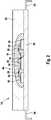
- the inertial sensor 14, as vehicle dynamics data 16 corresponds to the in Fig. 2 indicated lateral acceleration 26 detected on the vehicle and the yaw rate 28, with which the vehicle 2 rotates about its vertical axis, because they are usually used in the context of the aforementioned stability program.
- the invention is explained in more detail with reference to the inertial sensor 14, the invention can be applied to any desired sensors, such as the speed sensors 10 mentioned above.
- a transverse acceleration measuring sensor 30 is arranged in the inertial sensor 14.
- the lateral accelerometer 30 is exposed to a physical encoder field in the form of a centrifugal force field 32 which acts on the lateral accelerometer 30 and accelerates to the vehicle 2 with the lateral acceleration 26 to be detected.
- the detected lateral acceleration 26 is then output to a signal conditioning circuit 34.
- a Coriolis acceleration sensor 36 is arranged in the inertial sensor 14.
- the Coriolis accelerometer 36 is exposed to a physical donor field in the form of a Coriolis force field 38.
- the Coriolis accelerometer outputs 36, a transmitter signal from 40, which can then be converted into the yaw rate 28 in an optionally still belonging to the Coriolisbevantungsmessauf choir 36 evaluation device 42.
- An example of how the yaw rate 28 may be detected based on a Coriolis force field 38 is in the document DE 10 2010 002 796 A1 described why it should be omitted here for the sake of brevity.
- the detected yaw rate 28 is output to the signal conditioning circuit 34.
- the thus detected lateral acceleration 26 and yaw rate 28 can be post-processed, for example, to reduce the noise band gap and to increase the signal strength.
- the thus processed lateral acceleration 26 and yaw rate 28 can then be output to an interface 44, which then sends the two detected signals to the controller 18 as driving dynamics data 16.
- This interface 44 could, for example, be based on the PSI5 standard or the CAN standard.
- the two measuring sensors 30, 36 and the signal conditioning circuit 34 form a sensor circuit 46, which is carried and connected on a circuit carrier designed as a leadframe 48. If necessary, interconnections that can not be realized on the leadframe 48 can be realized here via electrical lines in the form of bonding wires 50.
- the interface 44 may be integrated into the signal conditioning circuit 34 and formed as an application specific integrated circuit, hereinafter called ASIC 34 (application-specific integrated circuit).
- the sensor circuit 46 may also be surrounded by a mechanical decoupling material 51, also called Globetop mass 51, in the form of a silicone material, which in turn is common in a die-cast material 52, such as a thermoset in the form of an epoxy resin 52 may be encapsulated.
- a mechanical decoupling material 51 also called Globetop mass 51
- a die-cast material 52 such as a thermoset in the form of an epoxy resin 52 may be encapsulated.
- corresponding contact possibilities protrude from the inertial sensor 14, as in FIG Fig. 2 shown legs 54 for making electrical contact with a circuit such as the controller 18 from.
- the inertial sensor 14 detecting the lateral acceleration 26 and / or the yaw rate 28 as driving dynamics data 16 could be soldered directly to a printed circuit board 56 in a reflow soldering process known per se, on which, for example, the controller 18 could also be realized.
- ceramic capacitors 58 could be located on this printed circuit board 56.
- structure-borne noise 64 generated by switched capacitors such as the ceramic capacitor 58 and / or the other technical elements, such as the aforementioned electric valve, which may be embodied, for example, as a solenoid valve, and / or body vibrations of the chassis 4 via the circuit board 56 and the legs 54 to the leadframe 48 and from there to the sensors 30, 36 can be passed.
- switched capacitors such as the ceramic capacitor 58 and / or the other technical elements, such as the aforementioned electric valve, which may be embodied, for example, as a solenoid valve, and / or body vibrations of the chassis 4 via the circuit board 56 and the legs 54 to the leadframe 48 and from there to the sensors 30, 36 can be passed.
- the structure-borne noise 64 excites the two measuring sensors 30, 36 to oscillate, which superimpose the centrifugal force field 32 and the Coriolis force field 38 and thus can influence the transverse acceleration 26 to be detected and / or the yaw rate 28 to be detected.
- This superposition with the encoder fields 32, 38 can thus lead to a faulty sensor signal in the form of Vehicle dynamics data 16 lead, which in turn can lead to erroneous reactions of the controller 18.
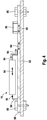
- the vibrations excited by the structure-borne sound 64 are to be damped with a sound resistance element 66.
- This sound resistance element 66 is designed as a slot 66 circulating around the sensor circuit 46 in the leadframe 48, so that the leadframe 48 is subdivided into a first region 68 and a second region 70.
- the two areas 68, 70 can thin webs 72, as in example Fig. 7 can be seen, connected with each other.
- the printed circuit board 48 is mounted below the sensor circuit 46 on a sound decoupling film 74, wherein the sound decoupling film 74 and the globetop material 51 can touch in the circumferential slot 66.
- the second area 70 of the leadframe 48 is above the in Fig. 5 not indicated legs 54 fixedly connected to the circuit board 56, which is indicated by fixed bearing 76.
- the first region 68 of the leadframe 48 is floatingly supported by the circumferential slot 66, so that it can not be excited by the structure-borne sound 64 to vibrate. Consequently, the sensors 30, 36 can not be made to oscillate and the vehicle dynamics data 16 can be falsified.
Landscapes
- Engineering & Computer Science (AREA)
- Physics & Mathematics (AREA)
- General Physics & Mathematics (AREA)
- Chemical & Material Sciences (AREA)
- Combustion & Propulsion (AREA)
- Mechanical Engineering (AREA)
- Transportation (AREA)
- Radar, Positioning & Navigation (AREA)
- Remote Sensing (AREA)
- Manufacturing & Machinery (AREA)
- Automation & Control Theory (AREA)
- Gyroscopes (AREA)
- Measurement Of Mechanical Vibrations Or Ultrasonic Waves (AREA)
Claims (8)
- Capteur (14) pour détecter un champ transmetteur (32, 38) physique dépendant d'une grandeur physique (16) à mesurer, comprenant :- un circuit capteur (46) destiné à détecter le champ transmetteur (32, 38) et destiné à délivrer un signal de capteur (26, 28) dépendant du champ transmetteur (32, 38),- un porte-circuit (48) ayant une première zone (68) dans laquelle est portée au moins une partie (34) du circuit capteur (46) et une deuxième zone (70) dans laquelle sont disposées au moins une première interface mécanique (54) et une deuxième interface mécanique (54) servant à attacher le porte-circuit (48) un élément de maintien (56), et- un élément de résistance acoustique (66) disposé entre la première zone (68) et la deuxième zone (70), lequel est conçu pour guider vers la deuxième interface mécanique (54) un bruit de structure (64) qui pénètre par le biais de la première interface mécanique (54), caractérisé en ce quele porte-circuit (48) est réalisé sous la forme d'une grille de connexion (48) et l'élément de résistance acoustique (66) sous la forme d'une fente (66) dans la grille de connexion (48), et
le capteur comporte un élément de découplage mécanique (51, 74) qui enveloppe la première zone (68) du porte-circuit (48), le circuit capteur (46) et au moins une partie de l'élément de résistance acoustique (66), l'élément de découplage mécanique (51, 74) comportant un film de découplage acoustique (74) sur lequel est supportée la première zone (68) du porte-circuit (48). - Capteur (14) selon la revendication 1, la fente (66) étant configurée périphérique autour de la première zone (68) et la deuxième zone (70) étant reliée à la première zone (68) par le biais d'au moins un élément jointif (72).
- Capteur (14) selon l'une des revendications précédentes, l'élément de découplage mécanique (51, 74) comportant une masse à sommet en globe (51).
- Capteur (14) selon la revendication 3, la première zone (68) du porte-circuit (48) étant accueillie entre la masse à sommet en globe (51) et le film de découplage acoustique (74).
- Capteur (14) selon l'une des revendications précédentes, un potentiel de référence électrique (82) étant appliqué à au moins l'une des deux interfaces mécaniques (52).
- Capteur (14) selon l'une des revendications précédentes, comprenant un composant de découplage (74) sur lequel est supportée au moins une partie (30, 36) du circuit capteur (46).
- Capteur (14) selon la revendication 6, le composant de découplage (74) étant le film de découplage acoustique (74).
- Capteur (14) selon l'une des revendications précédentes, comprenant une masse de protection (52) qui accueille le circuit capteur (46), la première zone (68) du porte-circuit (48) et au moins une partie de la deuxième zone (70) du porte-circuit (68).
Applications Claiming Priority (2)
| Application Number | Priority Date | Filing Date | Title |
|---|---|---|---|
| DE102014213217.7A DE102014213217A1 (de) | 2014-07-08 | 2014-07-08 | Körperschallentkopplung an mit Geberfeldern arbeitenden Sensoren |
| PCT/EP2015/064419 WO2016005202A1 (fr) | 2014-07-08 | 2015-06-25 | Découplage de bruits de structure dans des capteurs fonctionnant avec des champs de transmission |
Publications (2)
| Publication Number | Publication Date |
|---|---|
| EP3167253A1 EP3167253A1 (fr) | 2017-05-17 |
| EP3167253B1 true EP3167253B1 (fr) | 2019-03-20 |
Family
ID=53496671
Family Applications (1)
| Application Number | Title | Priority Date | Filing Date |
|---|---|---|---|
| EP15732631.5A Active EP3167253B1 (fr) | 2014-07-08 | 2015-06-25 | Découplage de vibration de capteurs |
Country Status (7)
| Country | Link |
|---|---|
| US (1) | US11118908B2 (fr) |
| EP (1) | EP3167253B1 (fr) |
| JP (1) | JP6383859B2 (fr) |
| KR (1) | KR101945640B1 (fr) |
| CN (1) | CN106662471B (fr) |
| DE (1) | DE102014213217A1 (fr) |
| WO (1) | WO2016005202A1 (fr) |
Families Citing this family (4)
| Publication number | Priority date | Publication date | Assignee | Title |
|---|---|---|---|---|
| DE102016203036A1 (de) * | 2016-02-26 | 2017-08-31 | Robert Bosch Gmbh | Sensorvorrichtung und Herstellungsverfahren für eine Sensorvorrichtung |
| DE102016112041A1 (de) * | 2016-06-30 | 2018-01-04 | Infineon Technologies Ag | Dämpfung eines sensors |
| US11760627B2 (en) * | 2021-06-10 | 2023-09-19 | Invensense, Inc. | MEMS stress reduction structure embedded into package |
| DE102021208776A1 (de) * | 2021-08-11 | 2023-02-16 | Zf Friedrichshafen Ag | Anordnung eines Sensorchips an einem Messobjekt |
Citations (2)
| Publication number | Priority date | Publication date | Assignee | Title |
|---|---|---|---|---|
| US5223738A (en) * | 1991-04-26 | 1993-06-29 | Mitsubishi Denki Kabushiki Kaisha | Leadframe |
| DE102012223982A1 (de) * | 2012-12-20 | 2014-06-26 | Continental Teves Ag & Co. Ohg | Verfahren zum Herstellen einer elektronischen Baugruppe |
Family Cites Families (29)
| Publication number | Priority date | Publication date | Assignee | Title |
|---|---|---|---|---|
| DE3623419A1 (de) * | 1986-07-11 | 1988-01-21 | Junghans Uhren Gmbh | Verfahren zum bestuecken eines leiterbahnen-netzwerkes fuer den schaltungstraeger eines elektromechanischen uhrwerks und teilbestuecktes leiterbahnen-netzwerk eines uhrwerks-schaltungstraegers |
| WO1989001873A1 (fr) * | 1987-08-26 | 1989-03-09 | Matsushita Electric Industrial Co., Ltd. | Dispositif a circuit integre et procede de fabrication dudit circuit |
| DE69211269T2 (de) * | 1991-09-24 | 1997-01-23 | Murata Manufacturing Co | Beschleunigungsmessaufnehmer |
| JP2852178B2 (ja) * | 1993-12-28 | 1999-01-27 | 日本電気株式会社 | フィルムキャリアテープ |
| CA2317659A1 (fr) | 1998-01-12 | 1999-07-15 | Andrew Nicholas Dames | Etiquetage magnetique comprenant des donnees |
| US6867483B2 (en) | 2000-09-13 | 2005-03-15 | Carsen Semiconductor Sdn. Bhd. | Stress-free lead frame |
| JP4637380B2 (ja) * | 2001-02-08 | 2011-02-23 | ルネサスエレクトロニクス株式会社 | 半導体装置 |
| FR2854495B1 (fr) * | 2003-04-29 | 2005-12-02 | St Microelectronics Sa | Procede de fabrication d'un boitier semi-conducteur et boitier semi-conducteur a grille. |
| DE102004015474A1 (de) * | 2004-03-26 | 2004-12-23 | Conti Temic Microelectronic Gmbh | Aufnehmersystem/Auslösesensor, geeignet für Diagnose-/Sicherheitsvorrichtung, insbesondere für Unfallschutzeinrichtungen in einem Fahrzeug |
| DE102004022808A1 (de) * | 2004-05-08 | 2005-12-01 | Conti Temic Microelectronic Gmbh | Aufnehmersystem/Auslösesensor, geeignet für Diagnose-/Sicherheitsvorrichtung, insbesondere für Unfallschutzeinrichtungen in einem Fahrzeug |
| DE102004022831A1 (de) * | 2004-05-08 | 2005-12-01 | Conti Temic Microelectronic Gmbh | Aufnehmersystem/Auslösesensor, geeignet für Diagnose-/Sicherheitsvorrichtung, insbesondere für Unfallschutzeinrichtungen in einem Fahrzeug |
| DE102004039924A1 (de) * | 2004-08-18 | 2006-02-23 | Robert Bosch Gmbh | Mikromechanischer Sensor mit reduzierten elektrischen Streufeldern |
| JP2009133625A (ja) * | 2006-03-14 | 2009-06-18 | Mitsubishi Electric Corp | 加速度センサ |
| DE102007017641A1 (de) * | 2007-04-13 | 2008-10-16 | Infineon Technologies Ag | Aushärtung von Schichten am Halbleitermodul mittels elektromagnetischer Felder |
| WO2009031285A1 (fr) * | 2007-09-03 | 2009-03-12 | Panasonic Corporation | Capteur de force d'inertie |
| JP4973443B2 (ja) * | 2007-10-22 | 2012-07-11 | 株式会社デンソー | センサ装置 |
| EP2112471A1 (fr) * | 2008-04-22 | 2009-10-28 | Microcomponents AG | Dispositif de montage pour composant électronique |
| JP4851555B2 (ja) * | 2008-05-13 | 2012-01-11 | 株式会社デンソー | 力学量センサおよびその製造方法 |
| DE102008064046A1 (de) | 2008-10-02 | 2010-04-08 | Continental Teves Ag & Co. Ohg | Verfahren zur Herstellung eines Geschwindigkeits-Sensorelementes |
| EP2406581B1 (fr) | 2009-03-11 | 2017-06-14 | Continental Teves AG & Co. oHG | Capteur de vitesse de rotation biaxial |
| JPWO2011018973A1 (ja) * | 2009-08-11 | 2013-01-17 | アルプス電気株式会社 | Memsセンサパッケージ |
| DE102010000848A1 (de) * | 2010-01-13 | 2011-07-14 | Robert Bosch GmbH, 70469 | Trägermaterial mit einer mechanischen Filtereigenschaft und Verfahren zur Herstellung eines Trägermaterials |
| JP5463173B2 (ja) * | 2010-03-12 | 2014-04-09 | 日立オートモティブシステムズ株式会社 | 角速度検出装置 |
| CN102196605B (zh) * | 2010-03-15 | 2014-02-26 | 国民技术股份有限公司 | 移动射频装置、射频ic卡及射频存储卡 |
| JP5732203B2 (ja) * | 2010-05-21 | 2015-06-10 | 日立オートモティブシステムズ株式会社 | 複合センサの製造方法 |
| CN103153729B (zh) | 2010-08-10 | 2016-08-03 | 大陆-特韦斯贸易合伙股份公司及两合公司 | 用于调节行驶稳定性的方法和系统 |
| DE102011017692A1 (de) * | 2011-04-28 | 2012-10-31 | Robert Bosch Gmbh | Leiterplattenanordnung mit einem schwingfähigen System |
| DE102012201486B4 (de) * | 2012-02-02 | 2020-08-06 | Robert Bosch Gmbh | Dämpfungsvorrichtung für eine mikromechanische Sensoreinrichtung |
| DE102013202212A1 (de) * | 2012-02-10 | 2013-08-14 | Continental Teves Ag & Co. Ohg | Zweistufig gemoldeter Sensor |
-
2014
- 2014-07-08 DE DE102014213217.7A patent/DE102014213217A1/de not_active Withdrawn
-
2015
- 2015-06-25 WO PCT/EP2015/064419 patent/WO2016005202A1/fr active Application Filing
- 2015-06-25 CN CN201580036814.3A patent/CN106662471B/zh active Active
- 2015-06-25 JP JP2017500813A patent/JP6383859B2/ja active Active
- 2015-06-25 US US15/323,845 patent/US11118908B2/en active Active
- 2015-06-25 KR KR1020177003452A patent/KR101945640B1/ko active IP Right Grant
- 2015-06-25 EP EP15732631.5A patent/EP3167253B1/fr active Active
Patent Citations (2)
| Publication number | Priority date | Publication date | Assignee | Title |
|---|---|---|---|---|
| US5223738A (en) * | 1991-04-26 | 1993-06-29 | Mitsubishi Denki Kabushiki Kaisha | Leadframe |
| DE102012223982A1 (de) * | 2012-12-20 | 2014-06-26 | Continental Teves Ag & Co. Ohg | Verfahren zum Herstellen einer elektronischen Baugruppe |
Also Published As
| Publication number | Publication date |
|---|---|
| WO2016005202A1 (fr) | 2016-01-14 |
| KR20170027842A (ko) | 2017-03-10 |
| JP6383859B2 (ja) | 2018-08-29 |
| US20170146345A1 (en) | 2017-05-25 |
| JP2017521659A (ja) | 2017-08-03 |
| CN106662471B (zh) | 2019-06-25 |
| DE102014213217A1 (de) | 2016-01-14 |
| US11118908B2 (en) | 2021-09-14 |
| CN106662471A (zh) | 2017-05-10 |
| KR101945640B1 (ko) | 2019-02-07 |
| EP3167253A1 (fr) | 2017-05-17 |
Similar Documents
| Publication | Publication Date | Title |
|---|---|---|
| EP3167253B1 (fr) | Découplage de vibration de capteurs | |
| EP1883825A1 (fr) | Systeme de detection de la vitesse de rotation d'une roue a securite intrinseque | |
| DE102014112495B4 (de) | Sensoranordnung und Verfahren zu dessen Herstellung | |
| DE102013214915A1 (de) | Verdrahtungseinrichtung zum Verdrahten einer elektronischen Vorrichtung | |
| WO2014095316A2 (fr) | Dispositif électronique et procédé de production d'un dispositif électronique | |
| EP3194897B1 (fr) | Détection d'humidité au sein d'un capteur | |
| WO2016005609A2 (fr) | Détecteur spécifique au client réalisé par triple moulage | |
| WO2016005201A1 (fr) | Capteur pourvu d'une anode sacrificielle | |
| EP2884232A1 (fr) | Mesure directe d'un champ de support dans un capteur de vitesse | |
| DE102015206299B4 (de) | Über Leiterplatte auf Leadframe verschaltete Sensorschaltung | |
| DE102005034589A1 (de) | Anordnung und Verfahren zur richtungssensitiven Erfassung mechanischer Schwingungen | |
| DE102004022831A1 (de) | Aufnehmersystem/Auslösesensor, geeignet für Diagnose-/Sicherheitsvorrichtung, insbesondere für Unfallschutzeinrichtungen in einem Fahrzeug | |
| EP3250893B1 (fr) | Capteur avec composants incorpores symetriquement | |
| WO2015162014A1 (fr) | Surveillance d'un capteur inertiel 3 axes au moyen d'un capteur inertiel 2 axes | |
| DE102014213590A1 (de) | Kundenspezifischer Adapter für Standardsensor | |
| WO2011085869A2 (fr) | Matériau de support avec une propriété de filtrage mécanique et procédé pour la fabrication d'un matériau de support | |
| EP3089228B1 (fr) | Composants dotés de forces de contrainte réduites dans un substrat | |
| DE102015207533A1 (de) | Schirmung als Silikonvergusshalter | |
| WO2016005200A1 (fr) | Composant passif connecté côté face inférieure d'un capteur | |
| DE102004022808A1 (de) | Aufnehmersystem/Auslösesensor, geeignet für Diagnose-/Sicherheitsvorrichtung, insbesondere für Unfallschutzeinrichtungen in einem Fahrzeug | |
| DE102014210523A1 (de) | Spannungsarmes Verkleben von Sensorchips | |
| DE102006057384B4 (de) | Halbleiterbauelement und Verfahren zum Herstellen eines solchen | |
| DE102011085727A1 (de) | Mikromechanisches Element, Bauelement mit einem mikromechanischen Element und Verfahren zum Herstellen eines Bauelements | |
| DE102004022822A1 (de) | Aufnehmersystem/Auslösesensor, geeignet für Diagnose-/Sicherheitsvorrichtung, insbesondere für Unfallschutzeinrichtungen in einem Fahrzeug | |
| WO2016005608A1 (fr) | Partie neutre d'un détecteur adaptable spécifiquement au client |
Legal Events
| Date | Code | Title | Description |
|---|---|---|---|
| STAA | Information on the status of an ep patent application or granted ep patent |
Free format text: STATUS: THE INTERNATIONAL PUBLICATION HAS BEEN MADE |
|
| PUAI | Public reference made under article 153(3) epc to a published international application that has entered the european phase |
Free format text: ORIGINAL CODE: 0009012 |
|
| STAA | Information on the status of an ep patent application or granted ep patent |
Free format text: STATUS: REQUEST FOR EXAMINATION WAS MADE |
|
| 17P | Request for examination filed |
Effective date: 20161208 |
|
| AK | Designated contracting states |
Kind code of ref document: A1 Designated state(s): AL AT BE BG CH CY CZ DE DK EE ES FI FR GB GR HR HU IE IS IT LI LT LU LV MC MK MT NL NO PL PT RO RS SE SI SK SM TR |
|
| AX | Request for extension of the european patent |
Extension state: BA ME |
|
| DAV | Request for validation of the european patent (deleted) | ||
| DAX | Request for extension of the european patent (deleted) | ||
| STAA | Information on the status of an ep patent application or granted ep patent |
Free format text: STATUS: EXAMINATION IS IN PROGRESS |
|
| 17Q | First examination report despatched |
Effective date: 20171221 |
|
| RAP1 | Party data changed (applicant data changed or rights of an application transferred) |
Owner name: CONTINENTAL TEVES AG & CO. OHG |
|
| GRAP | Despatch of communication of intention to grant a patent |
Free format text: ORIGINAL CODE: EPIDOSNIGR1 |
|
| STAA | Information on the status of an ep patent application or granted ep patent |
Free format text: STATUS: GRANT OF PATENT IS INTENDED |
|
| INTG | Intention to grant announced |
Effective date: 20181012 |
|
| GRAS | Grant fee paid |
Free format text: ORIGINAL CODE: EPIDOSNIGR3 |
|
| GRAA | (expected) grant |
Free format text: ORIGINAL CODE: 0009210 |
|
| STAA | Information on the status of an ep patent application or granted ep patent |
Free format text: STATUS: THE PATENT HAS BEEN GRANTED |
|
| AK | Designated contracting states |
Kind code of ref document: B1 Designated state(s): AL AT BE BG CH CY CZ DE DK EE ES FI FR GB GR HR HU IE IS IT LI LT LU LV MC MK MT NL NO PL PT RO RS SE SI SK SM TR |
|
| REG | Reference to a national code |
Ref country code: GB Ref legal event code: FG4D Free format text: NOT ENGLISH |
|
| REG | Reference to a national code |
Ref country code: CH Ref legal event code: EP |
|
| REG | Reference to a national code |
Ref country code: DE Ref legal event code: R096 Ref document number: 502015008411 Country of ref document: DE |
|
| REG | Reference to a national code |
Ref country code: AT Ref legal event code: REF Ref document number: 1111024 Country of ref document: AT Kind code of ref document: T Effective date: 20190415 |
|
| REG | Reference to a national code |
Ref country code: IE Ref legal event code: FG4D Free format text: LANGUAGE OF EP DOCUMENT: GERMAN |
|
| REG | Reference to a national code |
Ref country code: NL Ref legal event code: MP Effective date: 20190320 |
|
| PG25 | Lapsed in a contracting state [announced via postgrant information from national office to epo] |
Ref country code: LT Free format text: LAPSE BECAUSE OF FAILURE TO SUBMIT A TRANSLATION OF THE DESCRIPTION OR TO PAY THE FEE WITHIN THE PRESCRIBED TIME-LIMIT Effective date: 20190320 Ref country code: SE Free format text: LAPSE BECAUSE OF FAILURE TO SUBMIT A TRANSLATION OF THE DESCRIPTION OR TO PAY THE FEE WITHIN THE PRESCRIBED TIME-LIMIT Effective date: 20190320 Ref country code: NO Free format text: LAPSE BECAUSE OF FAILURE TO SUBMIT A TRANSLATION OF THE DESCRIPTION OR TO PAY THE FEE WITHIN THE PRESCRIBED TIME-LIMIT Effective date: 20190620 |
|
| REG | Reference to a national code |
Ref country code: LT Ref legal event code: MG4D |
|
| PG25 | Lapsed in a contracting state [announced via postgrant information from national office to epo] |
Ref country code: NL Free format text: LAPSE BECAUSE OF FAILURE TO SUBMIT A TRANSLATION OF THE DESCRIPTION OR TO PAY THE FEE WITHIN THE PRESCRIBED TIME-LIMIT Effective date: 20190320 Ref country code: RS Free format text: LAPSE BECAUSE OF FAILURE TO SUBMIT A TRANSLATION OF THE DESCRIPTION OR TO PAY THE FEE WITHIN THE PRESCRIBED TIME-LIMIT Effective date: 20190320 Ref country code: LV Free format text: LAPSE BECAUSE OF FAILURE TO SUBMIT A TRANSLATION OF THE DESCRIPTION OR TO PAY THE FEE WITHIN THE PRESCRIBED TIME-LIMIT Effective date: 20190320 Ref country code: HR Free format text: LAPSE BECAUSE OF FAILURE TO SUBMIT A TRANSLATION OF THE DESCRIPTION OR TO PAY THE FEE WITHIN THE PRESCRIBED TIME-LIMIT Effective date: 20190320 Ref country code: GR Free format text: LAPSE BECAUSE OF FAILURE TO SUBMIT A TRANSLATION OF THE DESCRIPTION OR TO PAY THE FEE WITHIN THE PRESCRIBED TIME-LIMIT Effective date: 20190621 Ref country code: BG Free format text: LAPSE BECAUSE OF FAILURE TO SUBMIT A TRANSLATION OF THE DESCRIPTION OR TO PAY THE FEE WITHIN THE PRESCRIBED TIME-LIMIT Effective date: 20190620 |
|
| PG25 | Lapsed in a contracting state [announced via postgrant information from national office to epo] |
Ref country code: SK Free format text: LAPSE BECAUSE OF FAILURE TO SUBMIT A TRANSLATION OF THE DESCRIPTION OR TO PAY THE FEE WITHIN THE PRESCRIBED TIME-LIMIT Effective date: 20190320 Ref country code: PT Free format text: LAPSE BECAUSE OF FAILURE TO SUBMIT A TRANSLATION OF THE DESCRIPTION OR TO PAY THE FEE WITHIN THE PRESCRIBED TIME-LIMIT Effective date: 20190720 Ref country code: ES Free format text: LAPSE BECAUSE OF FAILURE TO SUBMIT A TRANSLATION OF THE DESCRIPTION OR TO PAY THE FEE WITHIN THE PRESCRIBED TIME-LIMIT Effective date: 20190320 Ref country code: AL Free format text: LAPSE BECAUSE OF FAILURE TO SUBMIT A TRANSLATION OF THE DESCRIPTION OR TO PAY THE FEE WITHIN THE PRESCRIBED TIME-LIMIT Effective date: 20190320 Ref country code: CZ Free format text: LAPSE BECAUSE OF FAILURE TO SUBMIT A TRANSLATION OF THE DESCRIPTION OR TO PAY THE FEE WITHIN THE PRESCRIBED TIME-LIMIT Effective date: 20190320 Ref country code: RO Free format text: LAPSE BECAUSE OF FAILURE TO SUBMIT A TRANSLATION OF THE DESCRIPTION OR TO PAY THE FEE WITHIN THE PRESCRIBED TIME-LIMIT Effective date: 20190320 Ref country code: EE Free format text: LAPSE BECAUSE OF FAILURE TO SUBMIT A TRANSLATION OF THE DESCRIPTION OR TO PAY THE FEE WITHIN THE PRESCRIBED TIME-LIMIT Effective date: 20190320 |
|
| PG25 | Lapsed in a contracting state [announced via postgrant information from national office to epo] |
Ref country code: SM Free format text: LAPSE BECAUSE OF FAILURE TO SUBMIT A TRANSLATION OF THE DESCRIPTION OR TO PAY THE FEE WITHIN THE PRESCRIBED TIME-LIMIT Effective date: 20190320 Ref country code: PL Free format text: LAPSE BECAUSE OF FAILURE TO SUBMIT A TRANSLATION OF THE DESCRIPTION OR TO PAY THE FEE WITHIN THE PRESCRIBED TIME-LIMIT Effective date: 20190320 |
|
| PG25 | Lapsed in a contracting state [announced via postgrant information from national office to epo] |
Ref country code: IS Free format text: LAPSE BECAUSE OF FAILURE TO SUBMIT A TRANSLATION OF THE DESCRIPTION OR TO PAY THE FEE WITHIN THE PRESCRIBED TIME-LIMIT Effective date: 20190720 |
|
| REG | Reference to a national code |
Ref country code: DE Ref legal event code: R097 Ref document number: 502015008411 Country of ref document: DE |
|
| PLBE | No opposition filed within time limit |
Free format text: ORIGINAL CODE: 0009261 |
|
| STAA | Information on the status of an ep patent application or granted ep patent |
Free format text: STATUS: NO OPPOSITION FILED WITHIN TIME LIMIT |
|
| PG25 | Lapsed in a contracting state [announced via postgrant information from national office to epo] |
Ref country code: DK Free format text: LAPSE BECAUSE OF FAILURE TO SUBMIT A TRANSLATION OF THE DESCRIPTION OR TO PAY THE FEE WITHIN THE PRESCRIBED TIME-LIMIT Effective date: 20190320 Ref country code: MC Free format text: LAPSE BECAUSE OF FAILURE TO SUBMIT A TRANSLATION OF THE DESCRIPTION OR TO PAY THE FEE WITHIN THE PRESCRIBED TIME-LIMIT Effective date: 20190320 |
|
| REG | Reference to a national code |
Ref country code: CH Ref legal event code: PL |
|
| 26N | No opposition filed |
Effective date: 20200102 |
|
| GBPC | Gb: european patent ceased through non-payment of renewal fee |
Effective date: 20190625 |
|
| PG25 | Lapsed in a contracting state [announced via postgrant information from national office to epo] |
Ref country code: SI Free format text: LAPSE BECAUSE OF FAILURE TO SUBMIT A TRANSLATION OF THE DESCRIPTION OR TO PAY THE FEE WITHIN THE PRESCRIBED TIME-LIMIT Effective date: 20190320 |
|
| REG | Reference to a national code |
Ref country code: BE Ref legal event code: MM Effective date: 20190630 |
|
| PG25 | Lapsed in a contracting state [announced via postgrant information from national office to epo] |
Ref country code: TR Free format text: LAPSE BECAUSE OF FAILURE TO SUBMIT A TRANSLATION OF THE DESCRIPTION OR TO PAY THE FEE WITHIN THE PRESCRIBED TIME-LIMIT Effective date: 20190320 |
|
| PG25 | Lapsed in a contracting state [announced via postgrant information from national office to epo] |
Ref country code: GB Free format text: LAPSE BECAUSE OF NON-PAYMENT OF DUE FEES Effective date: 20190625 Ref country code: IE Free format text: LAPSE BECAUSE OF NON-PAYMENT OF DUE FEES Effective date: 20190625 |
|
| PG25 | Lapsed in a contracting state [announced via postgrant information from national office to epo] |
Ref country code: BE Free format text: LAPSE BECAUSE OF NON-PAYMENT OF DUE FEES Effective date: 20190630 Ref country code: LU Free format text: LAPSE BECAUSE OF NON-PAYMENT OF DUE FEES Effective date: 20190625 Ref country code: CH Free format text: LAPSE BECAUSE OF NON-PAYMENT OF DUE FEES Effective date: 20190630 Ref country code: LI Free format text: LAPSE BECAUSE OF NON-PAYMENT OF DUE FEES Effective date: 20190630 |
|
| PGFP | Annual fee paid to national office [announced via postgrant information from national office to epo] |
Ref country code: FR Payment date: 20200619 Year of fee payment: 6 Ref country code: FI Payment date: 20200622 Year of fee payment: 6 |
|
| PG25 | Lapsed in a contracting state [announced via postgrant information from national office to epo] |
Ref country code: CY Free format text: LAPSE BECAUSE OF FAILURE TO SUBMIT A TRANSLATION OF THE DESCRIPTION OR TO PAY THE FEE WITHIN THE PRESCRIBED TIME-LIMIT Effective date: 20190320 |
|
| PG25 | Lapsed in a contracting state [announced via postgrant information from national office to epo] |
Ref country code: MT Free format text: LAPSE BECAUSE OF FAILURE TO SUBMIT A TRANSLATION OF THE DESCRIPTION OR TO PAY THE FEE WITHIN THE PRESCRIBED TIME-LIMIT Effective date: 20190320 Ref country code: HU Free format text: LAPSE BECAUSE OF FAILURE TO SUBMIT A TRANSLATION OF THE DESCRIPTION OR TO PAY THE FEE WITHIN THE PRESCRIBED TIME-LIMIT; INVALID AB INITIO Effective date: 20150625 |
|
| REG | Reference to a national code |
Ref country code: AT Ref legal event code: MM01 Ref document number: 1111024 Country of ref document: AT Kind code of ref document: T Effective date: 20200625 |
|
| PG25 | Lapsed in a contracting state [announced via postgrant information from national office to epo] |
Ref country code: AT Free format text: LAPSE BECAUSE OF NON-PAYMENT OF DUE FEES Effective date: 20200625 |
|
| REG | Reference to a national code |
Ref country code: FI Ref legal event code: MAE |
|
| PG25 | Lapsed in a contracting state [announced via postgrant information from national office to epo] |
Ref country code: FI Free format text: LAPSE BECAUSE OF NON-PAYMENT OF DUE FEES Effective date: 20210625 |
|
| PG25 | Lapsed in a contracting state [announced via postgrant information from national office to epo] |
Ref country code: FR Free format text: LAPSE BECAUSE OF NON-PAYMENT OF DUE FEES Effective date: 20210630 |
|
| PG25 | Lapsed in a contracting state [announced via postgrant information from national office to epo] |
Ref country code: MK Free format text: LAPSE BECAUSE OF FAILURE TO SUBMIT A TRANSLATION OF THE DESCRIPTION OR TO PAY THE FEE WITHIN THE PRESCRIBED TIME-LIMIT Effective date: 20190320 |
|
| REG | Reference to a national code |
Ref country code: DE Ref legal event code: R081 Ref document number: 502015008411 Country of ref document: DE Owner name: CONTINENTAL AUTOMOTIVE TECHNOLOGIES GMBH, DE Free format text: FORMER OWNER: CONTINENTAL TEVES AG & CO. OHG, 60488 FRANKFURT, DE |
|
| REG | Reference to a national code |
Ref country code: DE Ref legal event code: R081 Ref document number: 502015008411 Country of ref document: DE Owner name: CONTINENTAL AUTOMOTIVE TECHNOLOGIES GMBH, DE Free format text: FORMER OWNER: CONTINENTAL AUTOMOTIVE TECHNOLOGIES GMBH, 30165 HANNOVER, DE |
|
| PGFP | Annual fee paid to national office [announced via postgrant information from national office to epo] |
Ref country code: DE Payment date: 20240630 Year of fee payment: 10 |
|
| PGFP | Annual fee paid to national office [announced via postgrant information from national office to epo] |
Ref country code: IT Payment date: 20240625 Year of fee payment: 10 |