EP3162995B1 - Beschlagteil eines beschlages für einen flügel eines fensters oder einer tür - Google Patents
Beschlagteil eines beschlages für einen flügel eines fensters oder einer tür Download PDFInfo
- Publication number
- EP3162995B1 EP3162995B1 EP15002847.0A EP15002847A EP3162995B1 EP 3162995 B1 EP3162995 B1 EP 3162995B1 EP 15002847 A EP15002847 A EP 15002847A EP 3162995 B1 EP3162995 B1 EP 3162995B1
- Authority
- EP
- European Patent Office
- Prior art keywords
- groove
- fitting part
- leg
- locking
- base body
- Prior art date
- Legal status (The legal status is an assumption and is not a legal conclusion. Google has not performed a legal analysis and makes no representation as to the accuracy of the status listed.)
- Active
Links
Images


Classifications
-
- E—FIXED CONSTRUCTIONS
- E05—LOCKS; KEYS; WINDOW OR DOOR FITTINGS; SAFES
- E05C—BOLTS OR FASTENING DEVICES FOR WINGS, SPECIALLY FOR DOORS OR WINDOWS
- E05C9/00—Arrangements of simultaneously actuated bolts or other securing devices at well-separated positions on the same wing
- E05C9/18—Details of fastening means or of fixed retaining means for the ends of bars
- E05C9/1825—Fastening means
- E05C9/1833—Fastening means performing sliding movements
- E05C9/185—Fastening means performing sliding movements parallel with actuating bar
-
- E—FIXED CONSTRUCTIONS
- E05—LOCKS; KEYS; WINDOW OR DOOR FITTINGS; SAFES
- E05C—BOLTS OR FASTENING DEVICES FOR WINGS, SPECIALLY FOR DOORS OR WINDOWS
- E05C9/00—Arrangements of simultaneously actuated bolts or other securing devices at well-separated positions on the same wing
- E05C9/22—Guides for sliding bars, rods or cables
-
- E—FIXED CONSTRUCTIONS
- E05—LOCKS; KEYS; WINDOW OR DOOR FITTINGS; SAFES
- E05B—LOCKS; ACCESSORIES THEREFOR; HANDCUFFS
- E05B17/00—Accessories in connection with locks
- E05B17/0004—Lock assembling or manufacturing
-
- E—FIXED CONSTRUCTIONS
- E05—LOCKS; KEYS; WINDOW OR DOOR FITTINGS; SAFES
- E05C—BOLTS OR FASTENING DEVICES FOR WINGS, SPECIALLY FOR DOORS OR WINDOWS
- E05C9/00—Arrangements of simultaneously actuated bolts or other securing devices at well-separated positions on the same wing
- E05C9/18—Details of fastening means or of fixed retaining means for the ends of bars
- E05C9/1825—Fastening means
- E05C9/1833—Fastening means performing sliding movements
- E05C9/185—Fastening means performing sliding movements parallel with actuating bar
- E05C9/1858—Fastening means performing sliding movements parallel with actuating bar of the roller bolt type
Definitions
- the invention relates to a fitting part arrangement according to the preamble of claim 1. Furthermore, the invention relates to a wing assembly with a wing of a window or a door, with a C-shaped groove having a first groove portion and a second groove portion in the fold frame profile of In addition, the invention relates to a method for the frontal assembly of a fitting part arrangement of the aforementioned type in a C-shaped groove in the fold of a frame profile of a wing of a window or door.
- a fitting refers to the totality of fittings that are mounted in the rebate of the wing and coupled to the fitting gear.
- the fitting mechanism is connected to a rotary handle provided on the outside of the wing, via which the individual fitting parts are actuated.
- the fitting parts are, for example, normally open, driving rods, tilting bars, corner deflections or guides of corresponding (turn-tilt) shears.
- the respective fitting parts are arranged in the fold of the frame of the respective wing. For this purpose, the frame profile of the wing in the fold on a C-shaped groove, in which the individual fitting parts are arranged displaceably and ultimately connected to the fitting gear.
- Another mounting principle is the frontal mounting. It is possible to use the individual fitting parts frontally in the slot opening of the C-shaped groove in the fold of the frame profile of the wing. In systems known from practice, which make use of the principle of frontal assembly, however, comparatively many components are required. In addition, the factory pre-assembly but also prepares a mounting of fittings on site some problems, as in the groove frontally inserted fittings can easily fall out of the groove during assembly, which makes installation difficult.
- a fitting part arrangement of the type mentioned is already out of the EP 2 754 802 A2 known.
- This arrangement has a first fitting part as a locking bar and a second fitting part as a closing element.
- the closing element can be inserted into the locking bar.
- the locking bar is in turn inserted into a groove of a fold of the wing.
- the closing element has laterally projecting groove portions, engage in the locking bars of the locking bar.
- Object of the present invention is therefore to solve the above problems in connection with the frontal assembly.
- the invention proposes to solve the above object, an overall system as a fitting part arrangement according to claim 1, a wing assembly according to claim 6 and a mounting method for frontal assembly according to claim 10 before.
- a first fitting part is proposed in the invention, which may be, for example, a drive rod, but may also represent the base or a base for another fitting part, wherein the fitting part due to its concrete configuration in the C-shaped groove can be pivoted in the fold of the wing and lowered in the pivoted state, in particular under the influence of gravity.
- the fitting part engages with its two edge regions the respective groove legs of the groove sections of the C-shaped groove, so that the fitting part pivoted into the groove can no longer fall out of the groove. This significantly facilitates both the factory installation and installation with built-in sash.
- the invention not only has significant assembly advantages. Due to the special design of the fitting part, it is also possible to use this in known frame profiles or to realize later. Ultimately, the groove depth of the individual groove portions of the C-shaped groove plays no role in the embodiment according to the invention, since it only on the width of the groove opening, that is the distance between the free ends of the groove legs, and the corresponding dimensions of the height of the fitting part and the Distance of the free end of the upper edge region to the lower edge of the leg arrives at the base body. The latter distance must ultimately be greater than the width of the slot opening of the C-shaped groove.
- the leg already mentioned above which is provided on the front side on the base body following the second edge region, is designed such that it serves for attaching or inserting the further fitting part.
- the leg is particularly angled, but in principle also an oblique course to form a V-shaped groove is possible.
- the leg has a double function.
- the underside of the leg serves as a stop on the second groove portion of the C-shaped groove and prevents too far immersion of the fitting part in the second groove portion.
- the leg together with the base body forms a groove into which the further fitting part can be used for assembly purposes, in order subsequently to be pivoted into the assembly position, so that edge-side mounting of the fitting part results.
- a form-fitting connection between the fitting part and the further fitting part is also provided in order to transmit the forces occurring during the actuation of the fitting can.
- at least one connecting means in particular an engagement opening, for coupling with the further fitting part is provided in or on the main body on the front side.
- two engagement openings are provided in the base body, while the rear side of the further fitting part, two corresponding projections are provided which engage in the engagement openings.
- the region of the basic body in or on which the connection means is provided is thickened relative to the first edge region ,
- the second edge region is thickened relative to the first edge region.
- the base body should otherwise consist of metal, preferably of aluminum.
- the second edge region of the base body is chamfered at its outer end.
- the chamfer is adapted to the pivoting movement during pivoting of the fitting part in the C-shaped groove.
- this has a bearing body, on the edge side an engagement leg is provided which is provided for engagement in the groove on the base body of the fitting part, which is formed by the leg on the base body.
- an engagement leg is provided which is provided for engagement in the groove on the base body of the fitting part, which is formed by the leg on the base body.
- the projection on the opposite side of the engagement leg has a slope.
- the scope of the slope ultimately takes into account the Einschwenkwinkel the other fitting part relative to the fitting.
- a blocking body having a locking device is provided on the bearing body on the opposite side of the engagement leg.
- the locking body has a locking leg for engaging behind the Nutschenkels the first groove portion of the C-shaped groove.
- the blocking body is a component movable relative to the bearing body.
- the locking body is spring-loaded in the direction of the free end of the locking leg. The spring load pushes the locking leg into the locking position.
- the blocking body is designed in the form of a click or latching connection, which engages behind the groove legs of the first groove portion of the C-shaped groove when the further fitting part is pivoted or pivoted onto the fitting part.
- a locking pin is provided on the front side of the bearing body. This can be mounted eccentrically to adjust a different pressure can.
- other fitting components may be provided on the bearing body in order to realize further fitting functions.
- the aforementioned locking pin is only an example of corresponding other hardware components.
- the invention also relates to a combination of at least one fitting part with at least one further fitting part.
- This combination is referred to herein as fitting part arrangement, which is characterized in that the further fitting part after insertion of the engaging leg in the Groove on the main body of the fitting part to the base body can be pivoted and with this in particular releasably connectable.
- the invention also relates to at least one fitting part arrangement in the installed state in a wing in the form of a wing assembly.
- the wing assembly in the groove of the frame profile of the wing, the first fitting part with which the second fitting part is in particular releasably connected.
- the distance of the groove base of the first groove portion to the free end of the groove leg of the second groove portion is greater than the height of the first fitting part, that is the distance of the respective ends of the edge portions of the body. This ensures that the first fitting part can be pivoted into the C-shaped groove with its first edge region inserted into the first groove section.
- the invention provides that engages at endmontêtierem fitting part and further fitting part of the engaging leg of the other fitting part in the groove on the base body of the fitting, while at the same time the aforementioned positive connection is realized and the locking leg engages behind the groove legs of the first groove portion.
- the invention provides a mounting method for frontal mounting of the fitting part and a mounting method for frontal mounting of the further fitting part.
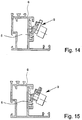
- the invention provides that the fitting part is inserted obliquely with its first edge region in the first groove portion, then in the C-shaped groove swung in and then lowered in the groove. This is done especially under the influence of gravity. The lowering takes place until the leg of the base body rests on the free end of the second groove leg of the second groove portion.
- the assembly of the further fitting part on the already introduced into the groove fitting part takes place such that the further fitting part is inserted with its engaging leg obliquely into the groove on the base body, then pivoted to the base body and then the locking leg is moved behind the groove legs of the first groove portion.
- This can be particularly supported by the fact that the locking leg is retracted against the spring force on the aforementioned operating portion and moved after reaching the end position during pivoting under the influence of spring force in the locked position.
- a wing assembly 1 is shown with a wing 2 of a window.
- the wing 2 is pivotally mounted on a frame 3.
- a handle 4 To open and close the wing 2 is a handle 4, which is rotatable from the illustrated vertically oriented position by 90 ° or 180 °.
- the handle 4 cooperates with a fitting mechanism, not shown, which in turn interacts with a fitting 5.
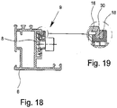
- the wing 2 has a peripheral frame profile 6, which has a frame 3 towards the open C-shaped groove 7. The groove 7 is thus arranged in the fold of the frame profile 6 of the wing 2.
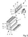
- the fitting 5 which may be located on one or on several sides in the fold of the frame profile 6 of the wing 1, has in the illustrated embodiment, a fitting 8 in the form of a drive rod and a further fitting part 9 in the form of a closer.
- the drive rod as a fitting part 8 has an elongated, flat base body 10, which has a front side 11 and a rear side 12. When installed, the back 12 faces the bottom 13 of the groove 7. The front side 11 of the main body 10 is directed into the fold.
- the base body 10 has at its opposite edge sides in the longitudinal or displacement direction of the fitting part 8 extending edge regions 14, 15. This is a first edge region 14, which is located in the assembled state of the fitting part 8 in the first groove portion 16 of the C-shaped groove, and a second edge region 15 which is in the mounted state in the second groove portion 17 of the groove 7. In the mounted state, the first edge region 14 engages behind the groove limb 18 of the first groove section 16, while the second edge region 15 engages behind the groove limb 19 of the second groove section 17.
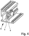
- an angled leg 20 is provided on the front side of the base body 10 following the second edge region 15.
- the leg 20 forms, together with the front 11 of the base body 10, a groove 21 which is provided for insertion of the further fitting part 9 and its edge-side support.
- the base body 10 in the present case has two engagement openings 22, which are provided for coupling to the further fitting part 9.
- the region of the main body 10, in which the engagement openings 22 are located is thickened relative to the first edge region 14.
- the second edge region 15 also has a greater thickness than the first edge region 14. The thickness of the second edge region 15 is slightly smaller than the groove width of the second groove portion 15 in the illustrated embodiment.
- the second edge portion 14 at its outer end a slope 23, whose function will be explained later in more detail.
- the main body 10 as such is made of aluminum.
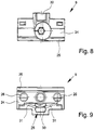
- the closer as a further fitting part 9 of the fitting 5 has a bearing body 24.
- the bearing body 24 has an engaging leg 25 for engagement in the groove 21 on the base body 10 of the fitting part 8.
- the engaging leg 25 extends over the entire length of the bearing body 24, while the angled leg 20 and the groove 21 extend over the entire length of the fitting part 8. Therefore, it would be fundamentally possible to arrange the further fitting part 9 at any desired location on the fitting part 8.
- the projections 26 have on the opposite side of the engagement leg 25 each have a slope 27.
- the locking device 28 there is a locking device 28 on the bearing body, which is mounted on the bearing body 24 on the engagement leg 25 opposite side.
- the locking device 28 has a locking body 29 with a locking leg 30.
- the locking leg 30 is provided for engaging behind the Nutschenkels 18 of the first groove portion 16 of the C-shaped groove 7 and formed.
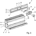
- the locking body 29 is spring-loaded.
- the locking body 29 is associated with a spring element.
- the spring element may be formed in several pieces. In the illustrated embodiment, two spring legs 31 are provided on the locking body 29, which urge the locking body 29 in the blocking position.
- the locking device 28 has an accessible from the front of the bearing body 24 operating portion 32, the actuation - in Fig. 12 by depressing against the spring force of the spring leg 31 - leads to the unlocking of the locking leg 30.
- the locking device 28 is made entirely of plastic, wherein the locking leg 30, the actuating portion 32 and the spring legs 31 are formed integrally with the locking body 29. It is understood that in principle it is also possible to produce the spring leg 31, for example, spring steel and then to store such a spring element on the locking body 29.
- an overlap leg 33 is provided on the engagement leg 25 opposite side of the bearing body 24, an overlap leg 33 is provided.
- the overlapping leg 33 engages over the outside of the groove leg 18 of the first groove portion 16 of the C-shaped groove 7.
- a receiving groove 34 is provided for the groove leg 18 of the first groove portion 16 between the cross-over leg 33 and the locking leg 31.
- a locking pin 35 is attached to the bearing body 24.
- the locking pin 35 is mounted eccentrically on the bearing body 24 in order to adjust the pressure when closing the wing 2, if necessary.
- the fitting line 8, 9 cooperate with each other and represent an assembly or a fitting part arrangement.
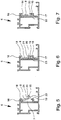
- the distance of the groove bottom of the first groove portion 16 to the free end of the groove leg 19 of the second groove portion 17 is greater than the height or width of the fitting part. Due to the above-mentioned dimensions, it is possible to swivel the fitting part 8 into the groove 7 with its first edge area 14 inserted into the first groove section 16. Otherwise, however, the height of the fitting part 8 is greater than the opening width of the groove 7.
- the in Fig. 7 is shown, which is provided on the base body 10 leg 20 on the free end of the groove leg 19 of the second groove portion 17. In this state, the first edge region 14 of the main body 10 engages behind the groove leg 18 of the first groove section 16 of the groove 7, while the second edge region 15 engages behind the groove leg 19 of the second groove section 17.
- the fitting part 8 is inserted with its first edge region 14 obliquely into the first groove portion 16, as in Fig. 5 is shown.
- the end of the first edge region 14 is then located in the rear corner region of the first groove section 16. This state is in Fig. 5 shown.
- the fitting part 8 is pivoted into the groove 7 until the back 12 abuts the bottom 13 of the groove 7.
- the fitting part 8 is pivoted into the groove 7 until the back 12 abuts the bottom 13 of the groove 7.
- the fitting part 8 is the in Fig. 6 achieved state shown.
- the fitting part 8 is lowered.
- the further fitting part 9 is mounted.
- the assembly can be done at the factory after the assembly of the first fitting part, or else, if necessary, at a later date, when the wing 2 is already mounted. This means that if a sufficient number of engagement openings 22 are provided on the fitting part 8, additional additional fitting parts can also be mounted in order, for example, to increase the safety standard of the wing 2.
Landscapes
- Engineering & Computer Science (AREA)
- Mechanical Engineering (AREA)
- Hinges (AREA)
- Securing Of Glass Panes Or The Like (AREA)
- Supports Or Holders For Household Use (AREA)
Priority Applications (1)
| Application Number | Priority Date | Filing Date | Title |
|---|---|---|---|
| PL15002847T PL3162995T3 (pl) | 2015-09-10 | 2015-10-06 | Część okucia dla skrzydła okna albo drzwi |
Applications Claiming Priority (1)
| Application Number | Priority Date | Filing Date | Title |
|---|---|---|---|
| EP15002643 | 2015-09-10 |
Publications (2)
| Publication Number | Publication Date |
|---|---|
| EP3162995A1 EP3162995A1 (de) | 2017-05-03 |
| EP3162995B1 true EP3162995B1 (de) | 2019-01-09 |
Family
ID=54106091
Family Applications (1)
| Application Number | Title | Priority Date | Filing Date |
|---|---|---|---|
| EP15002847.0A Active EP3162995B1 (de) | 2015-09-10 | 2015-10-06 | Beschlagteil eines beschlages für einen flügel eines fensters oder einer tür |
Country Status (4)
| Country | Link |
|---|---|
| EP (1) | EP3162995B1 (pl) |
| ES (1) | ES2719119T3 (pl) |
| PL (1) | PL3162995T3 (pl) |
| TR (1) | TR201904761T4 (pl) |
Families Citing this family (2)
| Publication number | Priority date | Publication date | Assignee | Title |
|---|---|---|---|---|
| US11866968B2 (en) * | 2019-09-17 | 2024-01-09 | Truth Hardware Corporation | Tie bar and guide for casement window |
| EP4215704B1 (de) * | 2022-01-19 | 2024-01-03 | Wilh. Schlechtendahl & Söhne GmbH & Co. KG | Sperrvorrichtung, beschlag und flügel-rahmenanordnung |
Family Cites Families (5)
| Publication number | Priority date | Publication date | Assignee | Title |
|---|---|---|---|---|
| DE29824769U1 (de) * | 1998-12-22 | 2002-07-11 | esco Metallbaubeschlag-Handel Gesellschaft mbH, 71254 Ditzingen | Schieberstange |
| DE10122438A1 (de) * | 2001-05-09 | 2002-11-14 | Roto Frank Ag | Fenster, Tür oder dergleichen mit Treibstangenbeschlag sowie Rahmenprofil und Treibstange hierfür |
| DE10157826A1 (de) * | 2001-11-24 | 2003-06-12 | Roto Frank Ag | Beschlag an einem Flügel oder einem festen Rahmen eines Fensters, einer Tür oder dergleichen |
| DE102007015199A1 (de) * | 2007-03-27 | 2008-10-02 | Hydro Building Systems Gmbh | Beschlag zur Verriegelung von Fenstern oder Türen |
| DE102013100309A1 (de) * | 2013-01-11 | 2014-07-17 | SCHÜCO International KG | Riegelstangenbeschlag für ein Fenster oder eine Tür |
-
2015
- 2015-10-06 EP EP15002847.0A patent/EP3162995B1/de active Active
- 2015-10-06 PL PL15002847T patent/PL3162995T3/pl unknown
- 2015-10-06 TR TR2019/04761T patent/TR201904761T4/tr unknown
- 2015-10-06 ES ES15002847T patent/ES2719119T3/es active Active
Non-Patent Citations (1)
| Title |
|---|
| None * |
Also Published As
| Publication number | Publication date |
|---|---|
| PL3162995T3 (pl) | 2019-08-30 |
| EP3162995A1 (de) | 2017-05-03 |
| TR201904761T4 (tr) | 2019-05-21 |
| ES2719119T3 (es) | 2019-07-08 |
Similar Documents
| Publication | Publication Date | Title |
|---|---|---|
| DE2920581C2 (de) | Zusatzverriegelung, insbesondere Mittelverriegelung, für Fenster, Türen od.dgl. | |
| DE3310020C2 (pl) | ||
| EP3798390B1 (de) | Faltanlage | |
| EP3266969B1 (de) | Eckumlenkung eines beschlages für einen flügel eines fensters oder einer tür | |
| EP4473179B1 (de) | Verlagerungsvorrichtung zur zwangsweisen verlagerung eines flügels, insbesondere eines schiebeflügels, eines fensters oder einer tür | |
| WO2015003872A1 (de) | Beschlag für ein fenster, eine tür oder dergleichen mit einem kipp- und schiebbaren flügel | |
| EP3162995B1 (de) | Beschlagteil eines beschlages für einen flügel eines fensters oder einer tür | |
| DE1932858C3 (de) | Durch ein Gestänge schwenkbare Ausstellschere für Fensterflügel oder dergleichen, insbesondere Oberlichter | |
| DE20008971U1 (de) | Hakenschwenkriegelschloß | |
| DE1584001C3 (de) | Beschlag für einen Schiebe-Schwenkflügel von Fenstern, Türen od.dgl | |
| DE29601966U1 (de) | Zusatzschloß für Flügel von Türen, Fenstern o.dgl. | |
| DE202010000634U1 (de) | Aussperrsicherung | |
| DE102015000606A1 (de) | Verriegelungsvorrichtung für einen schwenkbar gelagerten Flügel | |
| EP3425149A1 (de) | Hebe-schiebe-einrichtung, insbesondere hebe-schiebe-tür oder hebe-schiebe-fenster | |
| DE2658626B2 (de) | Schaltsperre für Treibstangenbeschläge | |
| DE2518318A1 (de) | Verriegelungsvorrichtung | |
| EP3299556A1 (de) | Verriegelungsvorrichtung für einen schwenkbar gelagerten flügel | |
| EP2453086B1 (de) | Treibstangenbeschlag für Standflügel von zweiflügeligen Fenstern oder Türen ohne Mittelpfosten | |
| DE102006002830B4 (de) | Ausstellvorrichtung für den Flügel eines Fensters oder dergleichen | |
| DE3221110A1 (de) | Beschlag fuer einen kipp- und nachfolgend mindestens parallelabstellbaren fluegel eines fensters, einer tuer od. dgl. | |
| DE10147989B4 (de) | Schaltschrank | |
| DE3041221C2 (de) | Verriegelungsbeschlag an einem Kipp-Schiebeflügel, vorzugsweise Hebe-Kipp-Schiebeflügel, von Fenstern, Türen od.dgl. | |
| DE2646905C2 (de) | Beschlag für einen kipp- und schiebbaren Flügel von Fenstern, Türen od. dgl. | |
| DE2461228A1 (de) | Verschlussvorrichtung fuer fenster, tueren oder dergleichen | |
| EP0262347A2 (de) | Ausstellvorrichtung für den wenigstens drehbaren Flügel eines Fensters, einer Tür od. dgl. |
Legal Events
| Date | Code | Title | Description |
|---|---|---|---|
| PUAI | Public reference made under article 153(3) epc to a published international application that has entered the european phase |
Free format text: ORIGINAL CODE: 0009012 |
|
| STAA | Information on the status of an ep patent application or granted ep patent |
Free format text: STATUS: THE APPLICATION HAS BEEN PUBLISHED |
|
| AK | Designated contracting states |
Kind code of ref document: A1 Designated state(s): AL AT BE BG CH CY CZ DE DK EE ES FI FR GB GR HR HU IE IS IT LI LT LU LV MC MK MT NL NO PL PT RO RS SE SI SK SM TR |
|
| AX | Request for extension of the european patent |
Extension state: BA ME |
|
| STAA | Information on the status of an ep patent application or granted ep patent |
Free format text: STATUS: REQUEST FOR EXAMINATION WAS MADE |
|
| 17P | Request for examination filed |
Effective date: 20170612 |
|
| RBV | Designated contracting states (corrected) |
Designated state(s): AL AT BE BG CH CY CZ DE DK EE ES FI FR GB GR HR HU IE IS IT LI LT LU LV MC MK MT NL NO PL PT RO RS SE SI SK SM TR |
|
| STAA | Information on the status of an ep patent application or granted ep patent |
Free format text: STATUS: EXAMINATION IS IN PROGRESS |
|
| 17Q | First examination report despatched |
Effective date: 20180220 |
|
| GRAP | Despatch of communication of intention to grant a patent |
Free format text: ORIGINAL CODE: EPIDOSNIGR1 |
|
| STAA | Information on the status of an ep patent application or granted ep patent |
Free format text: STATUS: GRANT OF PATENT IS INTENDED |
|
| INTG | Intention to grant announced |
Effective date: 20180913 |
|
| GRAS | Grant fee paid |
Free format text: ORIGINAL CODE: EPIDOSNIGR3 |
|
| GRAA | (expected) grant |
Free format text: ORIGINAL CODE: 0009210 |
|
| STAA | Information on the status of an ep patent application or granted ep patent |
Free format text: STATUS: THE PATENT HAS BEEN GRANTED |
|
| AK | Designated contracting states |
Kind code of ref document: B1 Designated state(s): AL AT BE BG CH CY CZ DE DK EE ES FI FR GB GR HR HU IE IS IT LI LT LU LV MC MK MT NL NO PL PT RO RS SE SI SK SM TR |
|
| REG | Reference to a national code |
Ref country code: GB Ref legal event code: FG4D Free format text: NOT ENGLISH |
|
| REG | Reference to a national code |
Ref country code: CH Ref legal event code: EP Ref country code: AT Ref legal event code: REF Ref document number: 1087502 Country of ref document: AT Kind code of ref document: T Effective date: 20190115 |
|
| REG | Reference to a national code |
Ref country code: DE Ref legal event code: R096 Ref document number: 502015007565 Country of ref document: DE |
|
| REG | Reference to a national code |
Ref country code: IE Ref legal event code: FG4D Free format text: LANGUAGE OF EP DOCUMENT: GERMAN |
|
| REG | Reference to a national code |
Ref country code: NL Ref legal event code: FP |
|
| REG | Reference to a national code |
Ref country code: LT Ref legal event code: MG4D |
|
| REG | Reference to a national code |
Ref country code: ES Ref legal event code: FG2A Ref document number: 2719119 Country of ref document: ES Kind code of ref document: T3 Effective date: 20190708 |
|
| PG25 | Lapsed in a contracting state [announced via postgrant information from national office to epo] |
Ref country code: LT Free format text: LAPSE BECAUSE OF FAILURE TO SUBMIT A TRANSLATION OF THE DESCRIPTION OR TO PAY THE FEE WITHIN THE PRESCRIBED TIME-LIMIT Effective date: 20190109 Ref country code: FI Free format text: LAPSE BECAUSE OF FAILURE TO SUBMIT A TRANSLATION OF THE DESCRIPTION OR TO PAY THE FEE WITHIN THE PRESCRIBED TIME-LIMIT Effective date: 20190109 Ref country code: SE Free format text: LAPSE BECAUSE OF FAILURE TO SUBMIT A TRANSLATION OF THE DESCRIPTION OR TO PAY THE FEE WITHIN THE PRESCRIBED TIME-LIMIT Effective date: 20190109 Ref country code: PT Free format text: LAPSE BECAUSE OF FAILURE TO SUBMIT A TRANSLATION OF THE DESCRIPTION OR TO PAY THE FEE WITHIN THE PRESCRIBED TIME-LIMIT Effective date: 20190509 Ref country code: NO Free format text: LAPSE BECAUSE OF FAILURE TO SUBMIT A TRANSLATION OF THE DESCRIPTION OR TO PAY THE FEE WITHIN THE PRESCRIBED TIME-LIMIT Effective date: 20190409 |
|
| PG25 | Lapsed in a contracting state [announced via postgrant information from national office to epo] |
Ref country code: GR Free format text: LAPSE BECAUSE OF FAILURE TO SUBMIT A TRANSLATION OF THE DESCRIPTION OR TO PAY THE FEE WITHIN THE PRESCRIBED TIME-LIMIT Effective date: 20190410 Ref country code: HR Free format text: LAPSE BECAUSE OF FAILURE TO SUBMIT A TRANSLATION OF THE DESCRIPTION OR TO PAY THE FEE WITHIN THE PRESCRIBED TIME-LIMIT Effective date: 20190109 Ref country code: RS Free format text: LAPSE BECAUSE OF FAILURE TO SUBMIT A TRANSLATION OF THE DESCRIPTION OR TO PAY THE FEE WITHIN THE PRESCRIBED TIME-LIMIT Effective date: 20190109 Ref country code: BG Free format text: LAPSE BECAUSE OF FAILURE TO SUBMIT A TRANSLATION OF THE DESCRIPTION OR TO PAY THE FEE WITHIN THE PRESCRIBED TIME-LIMIT Effective date: 20190409 Ref country code: IS Free format text: LAPSE BECAUSE OF FAILURE TO SUBMIT A TRANSLATION OF THE DESCRIPTION OR TO PAY THE FEE WITHIN THE PRESCRIBED TIME-LIMIT Effective date: 20190509 Ref country code: LV Free format text: LAPSE BECAUSE OF FAILURE TO SUBMIT A TRANSLATION OF THE DESCRIPTION OR TO PAY THE FEE WITHIN THE PRESCRIBED TIME-LIMIT Effective date: 20190109 |
|
| REG | Reference to a national code |
Ref country code: DE Ref legal event code: R097 Ref document number: 502015007565 Country of ref document: DE |
|
| PG25 | Lapsed in a contracting state [announced via postgrant information from national office to epo] |
Ref country code: CZ Free format text: LAPSE BECAUSE OF FAILURE TO SUBMIT A TRANSLATION OF THE DESCRIPTION OR TO PAY THE FEE WITHIN THE PRESCRIBED TIME-LIMIT Effective date: 20190109 Ref country code: AL Free format text: LAPSE BECAUSE OF FAILURE TO SUBMIT A TRANSLATION OF THE DESCRIPTION OR TO PAY THE FEE WITHIN THE PRESCRIBED TIME-LIMIT Effective date: 20190109 Ref country code: DK Free format text: LAPSE BECAUSE OF FAILURE TO SUBMIT A TRANSLATION OF THE DESCRIPTION OR TO PAY THE FEE WITHIN THE PRESCRIBED TIME-LIMIT Effective date: 20190109 Ref country code: EE Free format text: LAPSE BECAUSE OF FAILURE TO SUBMIT A TRANSLATION OF THE DESCRIPTION OR TO PAY THE FEE WITHIN THE PRESCRIBED TIME-LIMIT Effective date: 20190109 Ref country code: SK Free format text: LAPSE BECAUSE OF FAILURE TO SUBMIT A TRANSLATION OF THE DESCRIPTION OR TO PAY THE FEE WITHIN THE PRESCRIBED TIME-LIMIT Effective date: 20190109 Ref country code: RO Free format text: LAPSE BECAUSE OF FAILURE TO SUBMIT A TRANSLATION OF THE DESCRIPTION OR TO PAY THE FEE WITHIN THE PRESCRIBED TIME-LIMIT Effective date: 20190109 |
|
| PLBE | No opposition filed within time limit |
Free format text: ORIGINAL CODE: 0009261 |
|
| STAA | Information on the status of an ep patent application or granted ep patent |
Free format text: STATUS: NO OPPOSITION FILED WITHIN TIME LIMIT |
|
| PG25 | Lapsed in a contracting state [announced via postgrant information from national office to epo] |
Ref country code: SM Free format text: LAPSE BECAUSE OF FAILURE TO SUBMIT A TRANSLATION OF THE DESCRIPTION OR TO PAY THE FEE WITHIN THE PRESCRIBED TIME-LIMIT Effective date: 20190109 |
|
| 26N | No opposition filed |
Effective date: 20191010 |
|
| PG25 | Lapsed in a contracting state [announced via postgrant information from national office to epo] |
Ref country code: SI Free format text: LAPSE BECAUSE OF FAILURE TO SUBMIT A TRANSLATION OF THE DESCRIPTION OR TO PAY THE FEE WITHIN THE PRESCRIBED TIME-LIMIT Effective date: 20190109 |
|
| PG25 | Lapsed in a contracting state [announced via postgrant information from national office to epo] |
Ref country code: MC Free format text: LAPSE BECAUSE OF FAILURE TO SUBMIT A TRANSLATION OF THE DESCRIPTION OR TO PAY THE FEE WITHIN THE PRESCRIBED TIME-LIMIT Effective date: 20190109 |
|
| PG25 | Lapsed in a contracting state [announced via postgrant information from national office to epo] |
Ref country code: LU Free format text: LAPSE BECAUSE OF NON-PAYMENT OF DUE FEES Effective date: 20191006 |
|
| PG25 | Lapsed in a contracting state [announced via postgrant information from national office to epo] |
Ref country code: IE Free format text: LAPSE BECAUSE OF NON-PAYMENT OF DUE FEES Effective date: 20191006 |
|
| PG25 | Lapsed in a contracting state [announced via postgrant information from national office to epo] |
Ref country code: CY Free format text: LAPSE BECAUSE OF FAILURE TO SUBMIT A TRANSLATION OF THE DESCRIPTION OR TO PAY THE FEE WITHIN THE PRESCRIBED TIME-LIMIT Effective date: 20190109 |
|
| PG25 | Lapsed in a contracting state [announced via postgrant information from national office to epo] |
Ref country code: MT Free format text: LAPSE BECAUSE OF FAILURE TO SUBMIT A TRANSLATION OF THE DESCRIPTION OR TO PAY THE FEE WITHIN THE PRESCRIBED TIME-LIMIT Effective date: 20190109 Ref country code: HU Free format text: LAPSE BECAUSE OF FAILURE TO SUBMIT A TRANSLATION OF THE DESCRIPTION OR TO PAY THE FEE WITHIN THE PRESCRIBED TIME-LIMIT; INVALID AB INITIO Effective date: 20151006 |
|
| REG | Reference to a national code |
Ref country code: AT Ref legal event code: MM01 Ref document number: 1087502 Country of ref document: AT Kind code of ref document: T Effective date: 20201006 |
|
| PG25 | Lapsed in a contracting state [announced via postgrant information from national office to epo] |
Ref country code: AT Free format text: LAPSE BECAUSE OF NON-PAYMENT OF DUE FEES Effective date: 20201006 |
|
| PG25 | Lapsed in a contracting state [announced via postgrant information from national office to epo] |
Ref country code: MK Free format text: LAPSE BECAUSE OF FAILURE TO SUBMIT A TRANSLATION OF THE DESCRIPTION OR TO PAY THE FEE WITHIN THE PRESCRIBED TIME-LIMIT Effective date: 20190109 |
|
| P01 | Opt-out of the competence of the unified patent court (upc) registered |
Effective date: 20230613 |
|
| PGFP | Annual fee paid to national office [announced via postgrant information from national office to epo] |
Ref country code: TR Payment date: 20250929 Year of fee payment: 11 Ref country code: PL Payment date: 20250925 Year of fee payment: 11 |
|
| REG | Reference to a national code |
Ref country code: CH Ref legal event code: U11 Free format text: ST27 STATUS EVENT CODE: U-0-0-U10-U11 (AS PROVIDED BY THE NATIONAL OFFICE) Effective date: 20251101 |
|
| PGFP | Annual fee paid to national office [announced via postgrant information from national office to epo] |
Ref country code: NL Payment date: 20251021 Year of fee payment: 11 |
|
| PGFP | Annual fee paid to national office [announced via postgrant information from national office to epo] |
Ref country code: DE Payment date: 20251021 Year of fee payment: 11 |
|
| PGFP | Annual fee paid to national office [announced via postgrant information from national office to epo] |
Ref country code: GB Payment date: 20251022 Year of fee payment: 11 |
|
| PGFP | Annual fee paid to national office [announced via postgrant information from national office to epo] |
Ref country code: IT Payment date: 20251024 Year of fee payment: 11 |
|
| PGFP | Annual fee paid to national office [announced via postgrant information from national office to epo] |
Ref country code: FR Payment date: 20251030 Year of fee payment: 11 |
|
| PGFP | Annual fee paid to national office [announced via postgrant information from national office to epo] |
Ref country code: BE Payment date: 20251021 Year of fee payment: 11 |
|
| PGFP | Annual fee paid to national office [announced via postgrant information from national office to epo] |
Ref country code: CH Payment date: 20251101 Year of fee payment: 11 |
|
| PGFP | Annual fee paid to national office [announced via postgrant information from national office to epo] |
Ref country code: ES Payment date: 20251210 Year of fee payment: 11 |