EP3159183A1 - Luftloser reifen - Google Patents
Luftloser reifen Download PDFInfo
- Publication number
- EP3159183A1 EP3159183A1 EP16194565.4A EP16194565A EP3159183A1 EP 3159183 A1 EP3159183 A1 EP 3159183A1 EP 16194565 A EP16194565 A EP 16194565A EP 3159183 A1 EP3159183 A1 EP 3159183A1
- Authority
- EP
- European Patent Office
- Prior art keywords
- spokes
- outer edge
- inner edge
- tire
- tread ring
- Prior art date
- Legal status (The legal status is an assumption and is not a legal conclusion. Google has not performed a legal analysis and makes no representation as to the accuracy of the status listed.)
- Granted
Links
- 230000006835 compression Effects 0.000 claims abstract description 44
- 238000007906 compression Methods 0.000 claims abstract description 44
- 239000000463 material Substances 0.000 claims abstract description 6
- 239000013013 elastic material Substances 0.000 claims abstract description 4
- 230000002093 peripheral effect Effects 0.000 description 11
- 238000005452 bending Methods 0.000 description 6
- 230000000694 effects Effects 0.000 description 5
- 230000000052 comparative effect Effects 0.000 description 3
- 229920001971 elastomer Polymers 0.000 description 3
- 229920005989 resin Polymers 0.000 description 3
- 239000011347 resin Substances 0.000 description 3
- 229920001187 thermosetting polymer Polymers 0.000 description 3
- 229910000838 Al alloy Inorganic materials 0.000 description 1
- 229910000861 Mg alloy Inorganic materials 0.000 description 1
- 229910000831 Steel Inorganic materials 0.000 description 1
- 239000012141 concentrate Substances 0.000 description 1
- 230000007423 decrease Effects 0.000 description 1
- 230000006866 deterioration Effects 0.000 description 1
- 238000007599 discharging Methods 0.000 description 1
- 239000000806 elastomer Substances 0.000 description 1
- 230000020169 heat generation Effects 0.000 description 1
- 238000010438 heat treatment Methods 0.000 description 1
- 239000007769 metal material Substances 0.000 description 1
- 238000000034 method Methods 0.000 description 1
- 238000000465 moulding Methods 0.000 description 1
- 239000002861 polymer material Substances 0.000 description 1
- 229920005749 polyurethane resin Polymers 0.000 description 1
- 230000003014 reinforcing effect Effects 0.000 description 1
- 238000005096 rolling process Methods 0.000 description 1
- 239000010959 steel Substances 0.000 description 1
- 238000010998 test method Methods 0.000 description 1
- 229920002803 thermoplastic polyurethane Polymers 0.000 description 1
- XLYOFNOQVPJJNP-UHFFFAOYSA-N water Substances O XLYOFNOQVPJJNP-UHFFFAOYSA-N 0.000 description 1
Images


Classifications
-
- B—PERFORMING OPERATIONS; TRANSPORTING
- B60—VEHICLES IN GENERAL
- B60C—VEHICLE TYRES; TYRE INFLATION; TYRE CHANGING; CONNECTING VALVES TO INFLATABLE ELASTIC BODIES IN GENERAL; DEVICES OR ARRANGEMENTS RELATED TO TYRES
- B60C7/00—Non-inflatable or solid tyres
- B60C7/10—Non-inflatable or solid tyres characterised by means for increasing resiliency
- B60C7/14—Non-inflatable or solid tyres characterised by means for increasing resiliency using springs
-
- B—PERFORMING OPERATIONS; TRANSPORTING
- B60—VEHICLES IN GENERAL
- B60B—VEHICLE WHEELS; CASTORS; AXLES FOR WHEELS OR CASTORS; INCREASING WHEEL ADHESION
- B60B9/00—Wheels of high resiliency, e.g. with conical interacting pressure-surfaces
- B60B9/26—Wheels of high resiliency, e.g. with conical interacting pressure-surfaces comprising resilient spokes
-
- B—PERFORMING OPERATIONS; TRANSPORTING
- B60—VEHICLES IN GENERAL
- B60C—VEHICLE TYRES; TYRE INFLATION; TYRE CHANGING; CONNECTING VALVES TO INFLATABLE ELASTIC BODIES IN GENERAL; DEVICES OR ARRANGEMENTS RELATED TO TYRES
- B60C7/00—Non-inflatable or solid tyres
- B60C7/10—Non-inflatable or solid tyres characterised by means for increasing resiliency
- B60C7/14—Non-inflatable or solid tyres characterised by means for increasing resiliency using springs
- B60C7/16—Non-inflatable or solid tyres characterised by means for increasing resiliency using springs of helical or flat coil form
- B60C7/18—Non-inflatable or solid tyres characterised by means for increasing resiliency using springs of helical or flat coil form disposed radially relative to wheel axis
-
- B—PERFORMING OPERATIONS; TRANSPORTING
- B60—VEHICLES IN GENERAL
- B60C—VEHICLE TYRES; TYRE INFLATION; TYRE CHANGING; CONNECTING VALVES TO INFLATABLE ELASTIC BODIES IN GENERAL; DEVICES OR ARRANGEMENTS RELATED TO TYRES
- B60C7/00—Non-inflatable or solid tyres
- B60C7/10—Non-inflatable or solid tyres characterised by means for increasing resiliency
- B60C7/14—Non-inflatable or solid tyres characterised by means for increasing resiliency using springs
- B60C7/143—Non-inflatable or solid tyres characterised by means for increasing resiliency using springs having a lateral extension disposed in a plane parallel to the wheel axis
-
- B—PERFORMING OPERATIONS; TRANSPORTING
- B60—VEHICLES IN GENERAL
- B60C—VEHICLE TYRES; TYRE INFLATION; TYRE CHANGING; CONNECTING VALVES TO INFLATABLE ELASTIC BODIES IN GENERAL; DEVICES OR ARRANGEMENTS RELATED TO TYRES
- B60C7/00—Non-inflatable or solid tyres
- B60C7/10—Non-inflatable or solid tyres characterised by means for increasing resiliency
- B60C7/14—Non-inflatable or solid tyres characterised by means for increasing resiliency using springs
- B60C7/146—Non-inflatable or solid tyres characterised by means for increasing resiliency using springs extending substantially radially, e.g. like spokes
-
- B—PERFORMING OPERATIONS; TRANSPORTING
- B60—VEHICLES IN GENERAL
- B60B—VEHICLE WHEELS; CASTORS; AXLES FOR WHEELS OR CASTORS; INCREASING WHEEL ADHESION
- B60B2900/00—Purpose of invention
- B60B2900/30—Increase in
- B60B2900/313—Resiliency
Definitions
- the present invention relates to an airless tire capable of supporting a load by its own structure without using high-pressure air.
- Patent Documents 1 - 4 various airless tires have been proposed in Patent Documents 1 - 4 and the like.
- An airless tire can support a load by its own structure without using high-pressure air. Therefore, the airless tire has an advantage that it does not go flat.
- Fig. 6 illustrates a side view of a typical airless tire 100.
- the airless tire 100 includes a cylindrical tread ring 102 that is formed of an elastic body and has a ground contact surface, a metallic hub part 106 that is arranged on a radial direction inner side of the tread ring 102 and is fixed to an axle 104, and multiple spokes 108 for connecting the tread ring 102 and the hub part 106.
- the spokes 108 for example, are formed of a relatively soft elastomer material, and each have an outer edge (108a) that is fixed to the tread ring 102 side and an inner edge (108b) that is fixed to the hub part 106 side.
- the spokes 108 in a state in which a load is not applied to the tire, the spokes 108 each linearly extend along a tire radial plane 110 (a plane that contains a tire rotation axis (CL)).
- rigidity of the tread ring 102 is non-uniform in a tire circumferential direction.
- a portion that is connected to the outer edge (108a) of a spoke 108 has higher rigidity than a portion that is not connected to a spoke 108.
- high rigidity portions and low rigidity portions of the tread ring 102 alternately come into contact with a road surface, and thus there is a disadvantage that vibration occurs during running, resulting in poor riding comfort.
- an airless tire 200 illustrated in Figs. 7A and 7B is proposed in the following Patent Document 4.
- spokes 208 for connecting a tread ring 202 and a hub part 206 are inclined at an angle (0) with respect to the tire radial plane 110.
- spokes 208 allow rapid variation in rigidity of the tread ring 202 in the tire circumferential direction to be prevented, and thus an effect is expected that the above-described vibration during running is prevented and excellent riding comfort is provided.
- Fig. 7B is a developed view when the tread ring 202 is viewed from an inner peripheral surface side.
- an up-down direction corresponds to the tire circumferential direction.
- the airless tire of this example is structured such that, in the circumferential direction of the tread ring 202, the spokes 208 are always in contact with a road surface (actually, in contact with the road surface via the tread ring 202). Therefore, the airless tire 200 in this case effectively prevents the above-described vibration during running, and thus an effect is expected that excellent riding comfort is provided.
- each of the spokes repeats extension and bending.
- a relatively large bending force acts on a spoke 108 positioned directly above the ground contact surface of the tread ring 102, whereas a spoke positioned directly above the hub part 106 is relatively largely stretched by the hub part 106 that receives a vertical load. Therefore, for the spokes, a structure capable of withstanding mainly repeated bending and stretching is necessary.
- Fig. 8A illustrates a partial side view of the airless tire 200 in a no-load state
- Fig. 8B illustrates a state in which the airless tire 200 receives a vertical load and is in contact with a road surface.
- an outer edge (208a) of each of the spokes 208 that are obliquely connected to the tread ring 202 has an arc shape along an arc-shaped inner peripheral surface of the tread ring 202.
- the outer edge (208a) of a spoke 208 at a position directly above the ground contact surface of the tread ring 202 changes to have a linear shape along the inner peripheral surface of the tread ring 202 that has become flat.
- bending deformation occurs in a portion of the spoke 208 on the outer edge (208a) side, and an amount of the bending deformation is the largest near a central portion in the circumferential direction and gradually decreases toward both ends.
- the hub part 206 of the airless tire 200 is formed of a metallic material that substantially does not deform. Therefore, a portion of a spoke 208 on an inner edge (208b) side that is fixed to the hub part 206 is only bent in a direction in which a length is simply shortened.
- the present invention is accomplished in view of the above-described situation and is intended to provide an airless tire capable of improving durability of spokes.
- An airless tire according to the present invention include: a cylindrical tread ring that is formed of an elastic body and has a ground contact surface; a hub part that is formed of a substantially non-extensible material and that is arranged on a tire radial direction inner side of the tread ring and is fixed to an axle; and multiple spokes that are formed of an elastic material and connect the tread ring and the hub part.
- the spokes each has an outer edge that is fixed on the tread ring side and an inner edge that is fixed on the hub part side. The outer edge and the inner edge both extend obliquely with respect to a tire axial direction.
- a compression rigidity (Sr) of the outer edge side of each of the spokes is larger than a compression rigidity (Sh) of the inner edge side of each of the spokes.
- a ratio (Sh/Sr) between the compression rigidities be 0.95 or less.
- a ratio (Sh/Sr) between the compression rigidities be 0.20 - 0.95.
- an actual length (Ls) from the outer edge to the inner edge be 1.01 - 1.10 times a shortest distance (Ld) from the outer edge to the inner edge.
- a thickness (tr) of the outer edge side of each of the spokes can be larger than a thickness (th) of the inner edge side of each of the spokes.
- a curvature radius (Rh) of the inner edge side of each of the spokes be smaller than a curvature radius (Rr) of the outer edge side of each of the spokes.
- each of the spokes be provided on the same radial line that passes through a tire rotation axis.
- an inclination angle of the outer edge side of each of the spokes with respect to the radial line be smaller than an inclination angle of the inner edge side of each of the spokes with respect to the radial line.
- Durability of the spokes is governed by distortion due to repeated deformation of the spokes and by heat generation due to the distortion. Therefore, in order to improve the durability of the spokes, it is important that distortion is dispersed as much as possible so that a locally large distortion does not occur in the spokes.
- the airless tire of the present invention is structured such that the compression rigidity (Sr) of the outer edge side of each of the spokes is larger than the compression rigidity (Sh) of the inner edge side of each of the spokes.
- the airless tire of the present invention having the oblique spokes can significantly improve the durability while maintaining excellent riding comfort.
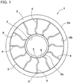
- Fig. 1 is illustrates overall side view of an airless tire 1 of the present embodiment.
- Fig. 2 illustrates a partial perspective view of the airless tire 1.
- the airless tire 1 of the present embodiment includes a cylindrical tread ring 2 formed of an elastic body, a hub part 3 that is arranged on a tire radial direction inner side of the tread ring 2, and multiple spokes 4 that are formed of an elastic material and are for connecting the tread ring 2 and the hub part 3.
- an airless tire designed for a passenger car is illustrated.
- the present invention is applicable as a tire for any vehicle.
- the tread ring 2 is a continuous annular body and has a ground contact surface (2a) and an inner peripheral surface (2b), the ground contact surface (2a) being in contact with a road surface, and the inner peripheral surface (2b) being on an opposite side of the ground contact surface (2a).
- the tread ring 2 for example, is formed of a rubber excellent in wear resistance and contains a cord reinforcing layer in the rubber.
- the ground contact surface (2a) and the inner peripheral surface (2b) are each formed as a cylindrical surface.
- Various patterns, such as grooves, recesses, and even through holes, can be provided on the ground contact surface (2a) for discharging water of the road surface to outside of the tire.
- the hub part 3 corresponds to a so-called wheel rim to be mounted on a pneumatic tire and is fixed on an axle (not illustrated in the drawings).
- the hub part 3, for example, is formed of a substantially inextensible material such as steel, an aluminum alloy or a magnesium alloy.
- the multiple spokes 4 are provided along a tire circumferential direction.
- the spokes 4 each have a plate-like shape.
- a transverse cross section of a spoke 4 along the tire radial direction is illustrated as being lightly colored.
- the spokes 4 are formed from a cast-molded body of a thermosetting resin, more specifically, a polyurethane resin.
- the tread ring 2 and the hub part 3 are arranged in advance in a mold, and the thermosetting resin is filled in the mold so as to connect the tread ring 2 and the hub part 3.
- the spokes 4 that connect the tread ring 2 and the hub part 3 are molded.
- a bonding layer 5 annularly continuously extending in the tire circumferential direction is provided on each of the inner peripheral surface (2b) of the tread ring 2 and an outer peripheral surface (3a) of the hub part 3.
- the bonding layers 5 of the present embodiment are formed of the substantially same material as the spokes 4. Such bonding layers 5 allow an outer edge 6 and an inner edge 7 of each of the spokes 4 to be respectively more firmly connected to the tread ring 2 and the hub part 3.
- the bonding layers 5 of the present embodiment are each formed to have a thickness of, for example, about 1 - 3 mm.
- the spokes 4 each have the outer edge 6 that is fixed to the tread ring 2 side and the inner edge 7 that is fixed to the hub part 3 side.
- the outer edge 6 of each of the spokes 4 is defined as an end part (end surface) excluding the bonding layer 5.
- the inner edge 7 of each of the spokes 4 is defined as an end part (end surface) excluding the bonding layer 5.
- the outer edges 6 and the inner edges 7 of the spokes 4 can be determined by imaginarily and smoothly connecting surfaces of portions of the bonding layers 5 where the spokes 4 are not provided.
- both the outer edge 6 and the inner edge 7 of each of the spokes 4 extend obliquely with respect to a tire axial direction from one end side to the other end side in a tire width direction.
- the outer edge 6 of each of the spokes 4 is inclined at an angle ( ⁇ 1) with respect to a tire radial plane 110 that contains a tire rotation axis (CL).
- the inner edge 7 of each of the spokes 4 is inclined at an angle (02) in the same orientation as the outer edge 6 with respect to the tire radial plane 110 that contains the tire rotation axis (CL).
- Such inclined spokes 4 relax variation in rigidity of the tread ring 2 in the tire circumferential direction, suppress vibration of the tire during running, and help to provide excellent riding comfort.
- each of the angles ( ⁇ 1, 02) of the spokes 4 be preferably about 10 - 70 degrees.
- the angle ( ⁇ 1) is substantially the same as the angle (02).
- the present invention is not limited to such an embodiment.
- an arrangement pitch of the spokes 4 in the tire circumferential direction for example, is equal to or less than a tire circumferential direction length of each of the spokes 4, the spokes 4 can be continuously in contact with a road surface via the tread ring 2 without interruption.
- Such an airless tire 1 can provide more excellent riding comfort.
- the outer edge 6 of the each of the spokes 4 is formed to have a surface of an arc shape that is convex toward a tire radial direction outer side.
- the spokes 4 are obliquely arranged with respect to the tire radial plane 110 and the outer peripheral surface (3a) of the hub part 3 is a cylindrical surface, the inner edge 7 of the each of the spokes 4 is formed to have a surface of a concave arc shape.
- a compression rigidity (Sr) of the outer edge 6 side of each of the spokes 4 is set to be larger than a compression rigidity (Sh) of the inner edge 7 side of each of the spokes 4.
- bending occurs in a spoke 4 due to deflection in the spoke 4.
- the deformation in which the outer edge 6 of an arc-shaped surface deforms to have a linear shape is further added.
- deformation of the inner edge 7 side of a spoke 4 (on the hub part 3 side) is basically only deformation due to the above-described deflection amount.
- the airless tire 1 of the present embodiment is structured such that, as described above, the compression rigidity (Sr) of the outer edge 6 side of each of the spokes 4 is larger than the compression rigidity (Sh) of the inner edge 7 side of each of the spokes 4.
- the compression rigidity (Sr) of the outer edge 6 side of each of the spokes 4 is larger than the compression rigidity (Sh) of the inner edge 7 side of each of the spokes 4.
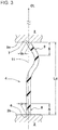
- Fig. 3 illustrates a transverse section (the lightly colored portion in Fig. 2 ) of the spoke 4 illustrated in Fig. 2 along the tire radial direction.
- the outer edge 6 and the inner edge 7 of each of the spokes 4 are provided on the same radial line 11 that passes through the tire rotation axis (CL).
- Such spokes 4 also are effective in suppressing vibration during running of the tire, and in particular, are effective in improving tangential force variation (TFV) and lateral force variation (LFV).
- the compression rigidity (Sr) of the outer edge 6 side of each of the spokes 4, when the airless tire 1 is in the no-load state, is defined as compression rigidity of an outer edge side portion 8 of each of the spokes 4 between the outer edge 6 and a position a distance (A) away from the outer edge 6 on a tire radial direction inner side.
- the compression rigidity (Sh) of the inner edge 7 side of a spoke 4 is defined as compression rigidity of an inner edge side portion 9 of the spoke 4 between the inner edge 7 and a position a distance (B) away from the inner edge 7 on a radial direction outer side.
- the distance (A) and the distance (B) are each 20% of a radial direction length of the spoke 4 (in this example, corresponding to a shortest distance (Ld) of the spoke of Fig. 3 ). This is because contribution of this portion to the rigidity of an edge side of a spoke is particularly large.
- the compression rigidity of the outer edge side portion 8 and the compression rigidity of the inner edge side portion 9 are each measured as follows. First, as illustrated in Figs. 4A and 4B , the outer edge side portion 8 and the inner edge side portion 9 are cut out from a spoke 4. Two ends of each of the outer edge side portion 8 and the inner edge side portion 9 are respectively fixed to jigs 10, 10 while maintaining a shape of each of the outer edge side portion 8 and the inner edge side portion 9 when the spoke is used (a shape in a no-load state). Next, a load (W) in a direction along the radial line 11 of Fig. 3 is applied to the 10, and a deflection amount ( ⁇ ) of each of the portions 8, 9 along the radial line 11 is measured. Then, based on a ratio (W/ ⁇ ) of the load (W) to the deflection amount ( ⁇ ), the compression rigidity of each of the outer edge side portion 8 and the inner edge side portion 9 is obtained.
- a ratio (Sh/Sr) between the compression rigidities of the spokes 4 is not particularly limited, but is preferably 0.95 or less, and more preferably 0.90 or less. This is preferable in that it allows distortion acting on the spokes 4 during running of the tire to be more effectively dispersed to the inner edge 7 side.
- a lower limit of the ratio (Sh/Sr) between the compression rigidities is also not particularly limited. However, when the ratio (Sh/Sr) is too small, there is a risk that the distortion acting on the spokes 4 during running of the tire is concentrated on the inner edge 7 side. Therefore, it is desirable that the ratio (Sh/Sr) be preferably 0.05 or more, and more preferably 0.10 or more, and even more preferably 0.20 or more.
- a mode is illustrated in which the outer edge side portion 8 of the spoke 4 is arranged along the radial direction, while the inner edge side portion 9 of the spoke 4 is arranged to be more significantly inclined with respect to the radial direction.
- the spoke 4 extends substantially straightly from the outer edge 6 along the radial direction and thereafter extends in a curved manner to reach the inner edge 7 so as to form a smooth curved shape that is convex toward one side in the tire circumferential direction.
- each of the spokes 4 be formed such that an actual length (Ls) from the outer edge 6 to the inner edge 7 (length measured along the shape) larger than the shortest distance (Ld) from the outer edge 6 to the inner edge 7.
- an elongation margin can be provided to a spoke 4 positioned directly above the hub part 3 for supporting a load.
- the actual length (Ls) of each of the spokes 4 be 1.01 or more times the shortest distance (Ld).
- a thickness (tr) of the outer edge 6 side of each of the spokes 4 is set to be substantially equal to a thickness (th) of the inner edge 7 side of each of the spokes 4 (0.8 ⁇ tr/th ⁇ 1.2).
- the thickness (tr) of the outer edge 6 side of each of the spokes 4 may be set to be larger than the thickness (th) of the inner edge 7 side of each of the spokes 4.
- the means for adjusting the rigidities by varying the thicknesses of the spokes 4 may be used in combination with the above-described mode or may be adopted separately and independently. Such a mode also allows the compression rigidity (Sr) of the outer edge 6 side of each of the spokes 4 to be set to be larger than the compression rigidity (Sh) of the inner edge 7 side of each of the spokes 4.
- the above-described thicknesses (tr, th), as illustrated in Figs. 4A and 4B are respectively defined as average thicknesses of the portions 8, 9 that are cut out from a spoke 4.
- the thicknesses (tr, th) are defined as thicknesses with the chamfer or the like excluded.
- the thickness (tr) of the outer edge 6 side of each of the spokes 4 be 1.2 or less times the thickness (th) of the inner edge 7 side of each of the spokes 4.
- a curvature radius (Rh) of the inner edge 7 side (the inner edge side portion 9) of each of the spokes 4 is set to be smaller than a curvature radius (Rr) of the outer edge 6 side (the outer edge side portion 8) of each of the spokes 4.
- This means may be used in combination with the above-described modes or may be adopted separately and independently.
- the curvature radius (Rr) of the outer edge side portion 8 is substantially infinitely large.
- the inner edge side portion 9 has a curvature that is convex toward one side only and the curvature radius (Rh) of the inner edge side portion 9 is set to be smaller than the curvature radius (Rr).
- the curvature radius (Rr) or the curvature radius (Rh) is identified by a single arc passing through three points including two ends 20, 20 of the portion and a middle portion 30 between the two ends 20, 20.
- Fig. 5 illustrates a transverse cross section of a spoke 4 of another embodiment along the tire radial direction.
- the spoke 4 extends substantially straightly from the outer edge 6 along the radial direction and thereafter extends to reach the inner edge 7 in a manner forming a smooth first curved portion 13 and a smooth second curved portion 14, the first curved portion 13 being convex toward one side in the tire circumferential direction, and the second curved portion 14 being convex toward the other side in the tire circumferential direction.
- the compression rigidity (Sr) of the outer edge 6 side is set to be larger than the compression rigidity (Sh) of the inner edge 7 side.
- an S-shaped transverse cross sectional shape excluding the portion that extends linearly in the radial direction may also be adopted.
- the compression rigidities can be adjusted by varying the curvature radii or thicknesses of the two curved portions 13, 14.
- the present invention includes any mode in which the compression rigidity (Sr) of the outer edge 6 side of each of the spokes 4 is larger than the compression rigidity (Sh) of the inner edge 7 of each of the spokes 4, which is the gist of the present invention.
- Airless tires (tires corresponding to a tire size of 125/80R13) that each form the basic structure of Figs. 1 - 4 were prototyped, and durability, tire weight and TFV were tested. All the tires were structured according to substantially the same specifications except for the spokes.
- the spokes were integrally molded with the tread ring and the hub part via the bonding layers using a cast molding method using a urethane resin (thermosetting resin).
- Main common specifications are as follows.
- a test method is as follows.
- each of the test tires was run under a load of 1.5 kN on a drum test machine, and a running time until a failure occurred in the tire was measured.
- the result is an index number with a running time of Comparative Example 1 as 100. A larger index number indicates a better durability.
- a weight per one airless tire was measured.
- the result is an index number with a weight of Comparative Example 1 as 100.
- a smaller index number indicates a better weight.
- TFV tangential force variation
- Example 1 The test results are illustrated in Table 1.
- Table 1 In Table 1, in Examples 1 - 3, a length ratio of the spokes was adjusted such that the compression rigidity ratio (Sh/Sr) of the spokes was not changed. Further, in Examples 4 - 7, the compression rigidity ratio (Sh/Sr) of the spokes was changed by changing inclination of the inner edge side and outer edge side of each of the spokes.
Landscapes
- Engineering & Computer Science (AREA)
- Mechanical Engineering (AREA)
- Tires In General (AREA)
Applications Claiming Priority (1)
| Application Number | Priority Date | Filing Date | Title |
|---|---|---|---|
| JP2015208349A JP6610161B2 (ja) | 2015-10-22 | 2015-10-22 | エアレスタイヤ |
Publications (2)
| Publication Number | Publication Date |
|---|---|
| EP3159183A1 true EP3159183A1 (de) | 2017-04-26 |
| EP3159183B1 EP3159183B1 (de) | 2020-09-02 |
Family
ID=57153389
Family Applications (1)
| Application Number | Title | Priority Date | Filing Date |
|---|---|---|---|
| EP16194565.4A Active EP3159183B1 (de) | 2015-10-22 | 2016-10-19 | Luftloser reifen |
Country Status (5)
| Country | Link |
|---|---|
| US (1) | US10406861B2 (de) |
| EP (1) | EP3159183B1 (de) |
| JP (1) | JP6610161B2 (de) |
| KR (1) | KR102581110B1 (de) |
| CN (1) | CN106608145B (de) |
Cited By (2)
| Publication number | Priority date | Publication date | Assignee | Title |
|---|---|---|---|---|
| CN111511580A (zh) * | 2017-12-21 | 2020-08-07 | 米其林集团总公司 | 用于非充气轮胎的加强型弹性支撑件 |
| CN114393956A (zh) * | 2022-03-10 | 2022-04-26 | 季华实验室 | 非充气轮胎 |
Families Citing this family (29)
| Publication number | Priority date | Publication date | Assignee | Title |
|---|---|---|---|---|
| EP3007909A4 (de) | 2013-06-15 | 2017-03-01 | Ronald Thompson | Ring und luftloser reifen |
| US10953696B2 (en) | 2015-02-04 | 2021-03-23 | Camso Inc | Non-pneumatic tire and other annular devices |
| JP1579281S (de) * | 2016-10-28 | 2017-06-19 | ||
| JP1576394S (de) * | 2016-10-28 | 2017-05-15 | ||
| USD832770S1 (en) | 2016-10-28 | 2018-11-06 | Bridgestone Corporation | Non-pneumatic tire |
| CA3067053A1 (en) | 2017-06-15 | 2018-12-20 | Camso Inc. | Wheel comprising a non-pneumatic tire |
| WO2019005125A1 (en) * | 2017-06-30 | 2019-01-03 | Compagnie Generale Des Etablissements Michelin | EDGE PROTECTION FOR A NON-PNEUMATIC WHEEL |
| JP6981102B2 (ja) | 2017-08-24 | 2021-12-15 | 住友ゴム工業株式会社 | エアレスタイヤ |
| CN111212743A (zh) * | 2017-09-08 | 2020-05-29 | 米其林集团总公司 | 轮辐和非气动轮 |
| US11584163B2 (en) * | 2017-11-02 | 2023-02-21 | The Goodyear Tire & Rubber Company | Non-pneumatic support structure |
| US11491819B2 (en) * | 2017-11-02 | 2022-11-08 | The Goodyear Tire & Rubber Company | Non-pneumatic support structure |
| JP7004562B2 (ja) * | 2017-12-14 | 2022-02-10 | Toyo Tire株式会社 | 非空気圧タイヤ |
| EP4253085A3 (de) * | 2018-07-27 | 2023-11-01 | Bridgestone Americas Tire Operations, LLC | Wiederverwendbare felge für luftlose reifen |
| JP7123771B2 (ja) | 2018-11-30 | 2022-08-23 | 株式会社ブリヂストン | 非空気入りタイヤ |
| JP7123770B2 (ja) * | 2018-11-30 | 2022-08-23 | 株式会社ブリヂストン | 非空気入りタイヤ |
| EP3902688B1 (de) * | 2018-12-28 | 2024-04-03 | Bridgestone Americas Tire Operations, LLC | Metallgewebe für einen luftlosen reifen und verfahren zur herstellung davon |
| CN111434496A (zh) * | 2019-01-11 | 2020-07-21 | 杨喜有 | 一种内置横卧枕型枕层弹力无充气轮胎 |
| USD883913S1 (en) * | 2019-02-28 | 2020-05-12 | The Goodyear Tire & Rubber Company | Tire |
| CN110091669A (zh) * | 2019-05-21 | 2019-08-06 | 浙江竤屹科技有限公司 | 一种缓冲减震性能良好的无气轮胎 |
| JP1654441S (de) * | 2019-05-23 | 2020-03-09 | ||
| JP1654332S (de) * | 2019-07-12 | 2020-03-09 | ||
| CN114585521B (zh) * | 2019-09-24 | 2023-11-17 | 普利司通美国轮胎运营有限责任公司 | 具有环状支撑结构的非充气轮胎及其制造方法 |
| EP3871902B1 (de) * | 2020-02-28 | 2023-07-19 | The Goodyear Tire & Rubber Company | Luftloser reifen |
| KR102412858B1 (ko) | 2020-11-25 | 2022-06-27 | 한국타이어앤테크놀로지 주식회사 | 비공기입 타이어 |
| KR102451806B1 (ko) | 2021-01-05 | 2022-10-07 | 한국타이어앤테크놀로지 주식회사 | 비공기입 타이어 및 그의 강성 조절 장치 |
| KR102495966B1 (ko) | 2021-01-18 | 2023-02-06 | 한국타이어앤테크놀로지 주식회사 | 날개를 포함하는 비공기입 타이어 |
| KR102519881B1 (ko) * | 2021-06-03 | 2023-04-11 | 금호타이어 주식회사 | 차량용 비공기입 타이어 |
| KR102602882B1 (ko) | 2021-08-10 | 2023-11-16 | 넥센타이어 주식회사 | 트레드의 변형을 저감한 비공기입 타이어 |
| KR200495989Y1 (ko) | 2022-04-20 | 2022-10-07 | 주식회사 지엘 | 차량 견인식 태양광 발전장치 |
Citations (11)
| Publication number | Priority date | Publication date | Assignee | Title |
|---|---|---|---|---|
| JPH01314602A (ja) * | 1988-06-13 | 1989-12-19 | Yokohama Rubber Co Ltd:The | 非空気式タイヤ |
| JPH03189202A (ja) * | 1989-12-20 | 1991-08-19 | Yokohama Rubber Co Ltd:The | 非空気式タイヤ |
| WO2007057975A1 (ja) * | 2005-11-21 | 2007-05-24 | Space Inc. | 弾性構造体タイヤ |
| JP4852767B2 (ja) | 2007-04-09 | 2012-01-11 | ソシエテ ド テクノロジー ミシュラン | 非空気圧タイヤ |
| JP4855646B2 (ja) | 2001-08-24 | 2012-01-18 | ソシエテ ド テクノロジー ミシュラン | 非空気圧タイヤ |
| JP4914211B2 (ja) | 2003-07-14 | 2012-04-11 | ソシエテ ド テクノロジー ミシュラン | コンプライアントホイール |
| JP5539479B2 (ja) | 2011-12-29 | 2014-07-02 | 韓国タイヤ株式會社 | 非空気入りタイヤ |
| US20140191564A1 (en) * | 2013-01-07 | 2014-07-10 | Gary Gebeau | Rim, airless tire and hubcap designs configured to directionally convey air and methods for their use |
| EP2801485A1 (de) * | 2013-05-07 | 2014-11-12 | Sumitomo Rubber Industries, Ltd. | Luftloser Reifen |
| WO2015098656A1 (ja) * | 2013-12-24 | 2015-07-02 | 住友ゴム工業株式会社 | エアレスタイヤ |
| CN204586332U (zh) * | 2015-04-15 | 2015-08-26 | 山东建筑大学 | 一种非充气轮胎 |
Family Cites Families (16)
| Publication number | Priority date | Publication date | Assignee | Title |
|---|---|---|---|---|
| JPS4914211B1 (de) | 1969-12-29 | 1974-04-05 | ||
| JPS5228704Y2 (de) | 1971-10-25 | 1977-06-30 | ||
| JPS5244379Y2 (de) | 1971-10-27 | 1977-10-07 | ||
| JPS53119362A (en) | 1977-03-29 | 1978-10-18 | Maruto Fujisawa Shiyouten Kk | Method of providing decorative pattern for handcrafted goods |
| JPS5539479U (de) | 1978-09-06 | 1980-03-13 | ||
| DE29608451U1 (de) * | 1996-05-09 | 1996-10-24 | Lemken Gmbh & Co Kg | Walze insbesondere Packerwalze |
| TWI261032B (en) * | 2005-10-25 | 2006-09-01 | Jiun-Guang Luo | Bicycle wheel rim assembly |
| EP1847407A2 (de) * | 2006-04-20 | 2007-10-24 | Chin-Kuang Luo | Radrahmen Vorrichtung |
| CN101448650A (zh) * | 2006-09-20 | 2009-06-03 | 米其林技术公司 | 用于非充气组件的可变刚度辐条 |
| FR2917994B1 (fr) * | 2007-06-28 | 2009-10-09 | Michelin Soc Tech | Toue pneumatique a mobilite etendue. |
| KR20120070469A (ko) * | 2010-12-21 | 2012-06-29 | 한국타이어 주식회사 | 비공기압 타이어 |
| KR101362120B1 (ko) * | 2011-11-22 | 2014-02-13 | 한국타이어 주식회사 | 에어리스 타이어 |
| US9266388B2 (en) * | 2012-09-27 | 2016-02-23 | Mtd Products Inc | Non-pneumatic tire |
| JP5930941B2 (ja) * | 2012-10-31 | 2016-06-08 | 株式会社ブリヂストン | 非空気入りタイヤ |
| JP2015113079A (ja) * | 2013-12-13 | 2015-06-22 | 東洋ゴム工業株式会社 | タイヤ・ホイール組立体 |
| CN104786731A (zh) * | 2015-04-22 | 2015-07-22 | 吉林大学 | 一种免充气越野车轮 |
-
2015
- 2015-10-22 JP JP2015208349A patent/JP6610161B2/ja active Active
-
2016
- 2016-10-11 KR KR1020160131167A patent/KR102581110B1/ko active IP Right Grant
- 2016-10-19 EP EP16194565.4A patent/EP3159183B1/de active Active
- 2016-10-20 CN CN201610916314.5A patent/CN106608145B/zh active Active
- 2016-10-21 US US15/331,529 patent/US10406861B2/en active Active
Patent Citations (11)
| Publication number | Priority date | Publication date | Assignee | Title |
|---|---|---|---|---|
| JPH01314602A (ja) * | 1988-06-13 | 1989-12-19 | Yokohama Rubber Co Ltd:The | 非空気式タイヤ |
| JPH03189202A (ja) * | 1989-12-20 | 1991-08-19 | Yokohama Rubber Co Ltd:The | 非空気式タイヤ |
| JP4855646B2 (ja) | 2001-08-24 | 2012-01-18 | ソシエテ ド テクノロジー ミシュラン | 非空気圧タイヤ |
| JP4914211B2 (ja) | 2003-07-14 | 2012-04-11 | ソシエテ ド テクノロジー ミシュラン | コンプライアントホイール |
| WO2007057975A1 (ja) * | 2005-11-21 | 2007-05-24 | Space Inc. | 弾性構造体タイヤ |
| JP4852767B2 (ja) | 2007-04-09 | 2012-01-11 | ソシエテ ド テクノロジー ミシュラン | 非空気圧タイヤ |
| JP5539479B2 (ja) | 2011-12-29 | 2014-07-02 | 韓国タイヤ株式會社 | 非空気入りタイヤ |
| US20140191564A1 (en) * | 2013-01-07 | 2014-07-10 | Gary Gebeau | Rim, airless tire and hubcap designs configured to directionally convey air and methods for their use |
| EP2801485A1 (de) * | 2013-05-07 | 2014-11-12 | Sumitomo Rubber Industries, Ltd. | Luftloser Reifen |
| WO2015098656A1 (ja) * | 2013-12-24 | 2015-07-02 | 住友ゴム工業株式会社 | エアレスタイヤ |
| CN204586332U (zh) * | 2015-04-15 | 2015-08-26 | 山东建筑大学 | 一种非充气轮胎 |
Cited By (3)
| Publication number | Priority date | Publication date | Assignee | Title |
|---|---|---|---|---|
| CN111511580A (zh) * | 2017-12-21 | 2020-08-07 | 米其林集团总公司 | 用于非充气轮胎的加强型弹性支撑件 |
| CN111511580B (zh) * | 2017-12-21 | 2022-09-16 | 米其林集团总公司 | 用于非充气轮胎的加强型弹性支撑件 |
| CN114393956A (zh) * | 2022-03-10 | 2022-04-26 | 季华实验室 | 非充气轮胎 |
Also Published As
| Publication number | Publication date |
|---|---|
| JP6610161B2 (ja) | 2019-11-27 |
| JP2017081199A (ja) | 2017-05-18 |
| KR20170047166A (ko) | 2017-05-04 |
| EP3159183B1 (de) | 2020-09-02 |
| CN106608145A (zh) | 2017-05-03 |
| KR102581110B1 (ko) | 2023-09-20 |
| US10406861B2 (en) | 2019-09-10 |
| CN106608145B (zh) | 2021-04-06 |
| US20170113490A1 (en) | 2017-04-27 |
Similar Documents
| Publication | Publication Date | Title |
|---|---|---|
| EP3159183B1 (de) | Luftloser reifen | |
| CN108608813B (zh) | 充气轮胎 | |
| EP3159187B1 (de) | Luftloser reifen | |
| US10569601B2 (en) | Tire with arched spokes | |
| EP3127717B1 (de) | Luftreifen | |
| CN109466251B (zh) | 免充气轮胎 | |
| US10870318B2 (en) | Pneumatic tire | |
| US10328753B2 (en) | Pneumatic tire | |
| JP2011005946A (ja) | 空気入りタイヤ | |
| JP2009279948A (ja) | 空気入りタイヤ | |
| JP4904075B2 (ja) | ランフラットタイヤ | |
| CN109760474B (zh) | 充气轮胎及其制造方法 | |
| EP2650144B1 (de) | Luftreifen | |
| JP2006272992A (ja) | 空気入りタイヤ及びその製造方法 | |
| US11148470B2 (en) | Zero-pressure tire | |
| US20150273954A1 (en) | Zero-pressure tire | |
| US10882364B2 (en) | Tire with concave sidewalls | |
| US20200198411A1 (en) | Tire with no ply turnup | |
| US20210061025A1 (en) | Tire with no bead turnup | |
| JP2020163898A (ja) | 空気入りタイヤ | |
| JP2015174459A (ja) | 空気入りタイヤ | |
| JP2019112038A (ja) | 空気入りタイヤ | |
| EP4046823A1 (de) | Luftloser reifen | |
| CN115742630A (zh) | 非充气轮胎 | |
| JP2019112040A (ja) | 空気入りタイヤ |
Legal Events
| Date | Code | Title | Description |
|---|---|---|---|
| PUAI | Public reference made under article 153(3) epc to a published international application that has entered the european phase |
Free format text: ORIGINAL CODE: 0009012 |
|
| STAA | Information on the status of an ep patent application or granted ep patent |
Free format text: STATUS: THE APPLICATION HAS BEEN PUBLISHED |
|
| AK | Designated contracting states |
Kind code of ref document: A1 Designated state(s): AL AT BE BG CH CY CZ DE DK EE ES FI FR GB GR HR HU IE IS IT LI LT LU LV MC MK MT NL NO PL PT RO RS SE SI SK SM TR |
|
| AX | Request for extension of the european patent |
Extension state: BA ME |
|
| STAA | Information on the status of an ep patent application or granted ep patent |
Free format text: STATUS: REQUEST FOR EXAMINATION WAS MADE |
|
| 17P | Request for examination filed |
Effective date: 20171023 |
|
| RBV | Designated contracting states (corrected) |
Designated state(s): AL AT BE BG CH CY CZ DE DK EE ES FI FR GB GR HR HU IE IS IT LI LT LU LV MC MK MT NL NO PL PT RO RS SE SI SK SM TR |
|
| STAA | Information on the status of an ep patent application or granted ep patent |
Free format text: STATUS: EXAMINATION IS IN PROGRESS |
|
| 17Q | First examination report despatched |
Effective date: 20190213 |
|
| GRAP | Despatch of communication of intention to grant a patent |
Free format text: ORIGINAL CODE: EPIDOSNIGR1 |
|
| STAA | Information on the status of an ep patent application or granted ep patent |
Free format text: STATUS: GRANT OF PATENT IS INTENDED |
|
| INTG | Intention to grant announced |
Effective date: 20200319 |
|
| GRAS | Grant fee paid |
Free format text: ORIGINAL CODE: EPIDOSNIGR3 |
|
| GRAA | (expected) grant |
Free format text: ORIGINAL CODE: 0009210 |
|
| STAA | Information on the status of an ep patent application or granted ep patent |
Free format text: STATUS: THE PATENT HAS BEEN GRANTED |
|
| AK | Designated contracting states |
Kind code of ref document: B1 Designated state(s): AL AT BE BG CH CY CZ DE DK EE ES FI FR GB GR HR HU IE IS IT LI LT LU LV MC MK MT NL NO PL PT RO RS SE SI SK SM TR |
|
| REG | Reference to a national code |
Ref country code: GB Ref legal event code: FG4D |
|
| REG | Reference to a national code |
Ref country code: AT Ref legal event code: REF Ref document number: 1308416 Country of ref document: AT Kind code of ref document: T Effective date: 20200915 Ref country code: CH Ref legal event code: EP |
|
| REG | Reference to a national code |
Ref country code: DE Ref legal event code: R096 Ref document number: 602016043093 Country of ref document: DE |
|
| REG | Reference to a national code |
Ref country code: IE Ref legal event code: FG4D |
|
| REG | Reference to a national code |
Ref country code: LT Ref legal event code: MG4D |
|
| PG25 | Lapsed in a contracting state [announced via postgrant information from national office to epo] |
Ref country code: SE Free format text: LAPSE BECAUSE OF FAILURE TO SUBMIT A TRANSLATION OF THE DESCRIPTION OR TO PAY THE FEE WITHIN THE PRESCRIBED TIME-LIMIT Effective date: 20200902 Ref country code: BG Free format text: LAPSE BECAUSE OF FAILURE TO SUBMIT A TRANSLATION OF THE DESCRIPTION OR TO PAY THE FEE WITHIN THE PRESCRIBED TIME-LIMIT Effective date: 20201202 Ref country code: GR Free format text: LAPSE BECAUSE OF FAILURE TO SUBMIT A TRANSLATION OF THE DESCRIPTION OR TO PAY THE FEE WITHIN THE PRESCRIBED TIME-LIMIT Effective date: 20201203 Ref country code: LT Free format text: LAPSE BECAUSE OF FAILURE TO SUBMIT A TRANSLATION OF THE DESCRIPTION OR TO PAY THE FEE WITHIN THE PRESCRIBED TIME-LIMIT Effective date: 20200902 Ref country code: HR Free format text: LAPSE BECAUSE OF FAILURE TO SUBMIT A TRANSLATION OF THE DESCRIPTION OR TO PAY THE FEE WITHIN THE PRESCRIBED TIME-LIMIT Effective date: 20200902 Ref country code: FI Free format text: LAPSE BECAUSE OF FAILURE TO SUBMIT A TRANSLATION OF THE DESCRIPTION OR TO PAY THE FEE WITHIN THE PRESCRIBED TIME-LIMIT Effective date: 20200902 Ref country code: NO Free format text: LAPSE BECAUSE OF FAILURE TO SUBMIT A TRANSLATION OF THE DESCRIPTION OR TO PAY THE FEE WITHIN THE PRESCRIBED TIME-LIMIT Effective date: 20201202 |
|
| REG | Reference to a national code |
Ref country code: NL Ref legal event code: MP Effective date: 20200902 |
|
| REG | Reference to a national code |
Ref country code: AT Ref legal event code: MK05 Ref document number: 1308416 Country of ref document: AT Kind code of ref document: T Effective date: 20200902 |
|
| PG25 | Lapsed in a contracting state [announced via postgrant information from national office to epo] |
Ref country code: RS Free format text: LAPSE BECAUSE OF FAILURE TO SUBMIT A TRANSLATION OF THE DESCRIPTION OR TO PAY THE FEE WITHIN THE PRESCRIBED TIME-LIMIT Effective date: 20200902 Ref country code: PL Free format text: LAPSE BECAUSE OF FAILURE TO SUBMIT A TRANSLATION OF THE DESCRIPTION OR TO PAY THE FEE WITHIN THE PRESCRIBED TIME-LIMIT Effective date: 20200902 Ref country code: LV Free format text: LAPSE BECAUSE OF FAILURE TO SUBMIT A TRANSLATION OF THE DESCRIPTION OR TO PAY THE FEE WITHIN THE PRESCRIBED TIME-LIMIT Effective date: 20200902 |
|
| PG25 | Lapsed in a contracting state [announced via postgrant information from national office to epo] |
Ref country code: EE Free format text: LAPSE BECAUSE OF FAILURE TO SUBMIT A TRANSLATION OF THE DESCRIPTION OR TO PAY THE FEE WITHIN THE PRESCRIBED TIME-LIMIT Effective date: 20200902 Ref country code: CZ Free format text: LAPSE BECAUSE OF FAILURE TO SUBMIT A TRANSLATION OF THE DESCRIPTION OR TO PAY THE FEE WITHIN THE PRESCRIBED TIME-LIMIT Effective date: 20200902 Ref country code: RO Free format text: LAPSE BECAUSE OF FAILURE TO SUBMIT A TRANSLATION OF THE DESCRIPTION OR TO PAY THE FEE WITHIN THE PRESCRIBED TIME-LIMIT Effective date: 20200902 Ref country code: PT Free format text: LAPSE BECAUSE OF FAILURE TO SUBMIT A TRANSLATION OF THE DESCRIPTION OR TO PAY THE FEE WITHIN THE PRESCRIBED TIME-LIMIT Effective date: 20210104 Ref country code: SM Free format text: LAPSE BECAUSE OF FAILURE TO SUBMIT A TRANSLATION OF THE DESCRIPTION OR TO PAY THE FEE WITHIN THE PRESCRIBED TIME-LIMIT Effective date: 20200902 Ref country code: NL Free format text: LAPSE BECAUSE OF FAILURE TO SUBMIT A TRANSLATION OF THE DESCRIPTION OR TO PAY THE FEE WITHIN THE PRESCRIBED TIME-LIMIT Effective date: 20200902 |
|
| PG25 | Lapsed in a contracting state [announced via postgrant information from national office to epo] |
Ref country code: ES Free format text: LAPSE BECAUSE OF FAILURE TO SUBMIT A TRANSLATION OF THE DESCRIPTION OR TO PAY THE FEE WITHIN THE PRESCRIBED TIME-LIMIT Effective date: 20200902 Ref country code: AL Free format text: LAPSE BECAUSE OF FAILURE TO SUBMIT A TRANSLATION OF THE DESCRIPTION OR TO PAY THE FEE WITHIN THE PRESCRIBED TIME-LIMIT Effective date: 20200902 Ref country code: AT Free format text: LAPSE BECAUSE OF FAILURE TO SUBMIT A TRANSLATION OF THE DESCRIPTION OR TO PAY THE FEE WITHIN THE PRESCRIBED TIME-LIMIT Effective date: 20200902 Ref country code: IS Free format text: LAPSE BECAUSE OF FAILURE TO SUBMIT A TRANSLATION OF THE DESCRIPTION OR TO PAY THE FEE WITHIN THE PRESCRIBED TIME-LIMIT Effective date: 20210102 |
|
| REG | Reference to a national code |
Ref country code: CH Ref legal event code: PL |
|
| REG | Reference to a national code |
Ref country code: DE Ref legal event code: R097 Ref document number: 602016043093 Country of ref document: DE |
|
| PG25 | Lapsed in a contracting state [announced via postgrant information from national office to epo] |
Ref country code: MC Free format text: LAPSE BECAUSE OF FAILURE TO SUBMIT A TRANSLATION OF THE DESCRIPTION OR TO PAY THE FEE WITHIN THE PRESCRIBED TIME-LIMIT Effective date: 20200902 Ref country code: LU Free format text: LAPSE BECAUSE OF NON-PAYMENT OF DUE FEES Effective date: 20201019 Ref country code: SK Free format text: LAPSE BECAUSE OF FAILURE TO SUBMIT A TRANSLATION OF THE DESCRIPTION OR TO PAY THE FEE WITHIN THE PRESCRIBED TIME-LIMIT Effective date: 20200902 |
|
| PLBE | No opposition filed within time limit |
Free format text: ORIGINAL CODE: 0009261 |
|
| STAA | Information on the status of an ep patent application or granted ep patent |
Free format text: STATUS: NO OPPOSITION FILED WITHIN TIME LIMIT |
|
| REG | Reference to a national code |
Ref country code: BE Ref legal event code: MM Effective date: 20201031 |
|
| 26N | No opposition filed |
Effective date: 20210603 |
|
| GBPC | Gb: european patent ceased through non-payment of renewal fee |
Effective date: 20201202 |
|
| PG25 | Lapsed in a contracting state [announced via postgrant information from national office to epo] |
Ref country code: LI Free format text: LAPSE BECAUSE OF NON-PAYMENT OF DUE FEES Effective date: 20201031 Ref country code: SI Free format text: LAPSE BECAUSE OF FAILURE TO SUBMIT A TRANSLATION OF THE DESCRIPTION OR TO PAY THE FEE WITHIN THE PRESCRIBED TIME-LIMIT Effective date: 20200902 Ref country code: DK Free format text: LAPSE BECAUSE OF FAILURE TO SUBMIT A TRANSLATION OF THE DESCRIPTION OR TO PAY THE FEE WITHIN THE PRESCRIBED TIME-LIMIT Effective date: 20200902 Ref country code: BE Free format text: LAPSE BECAUSE OF NON-PAYMENT OF DUE FEES Effective date: 20201031 Ref country code: CH Free format text: LAPSE BECAUSE OF NON-PAYMENT OF DUE FEES Effective date: 20201031 |
|
| PG25 | Lapsed in a contracting state [announced via postgrant information from national office to epo] |
Ref country code: IT Free format text: LAPSE BECAUSE OF FAILURE TO SUBMIT A TRANSLATION OF THE DESCRIPTION OR TO PAY THE FEE WITHIN THE PRESCRIBED TIME-LIMIT Effective date: 20200902 Ref country code: IE Free format text: LAPSE BECAUSE OF NON-PAYMENT OF DUE FEES Effective date: 20201019 |
|
| PG25 | Lapsed in a contracting state [announced via postgrant information from national office to epo] |
Ref country code: GB Free format text: LAPSE BECAUSE OF NON-PAYMENT OF DUE FEES Effective date: 20201202 |
|
| PG25 | Lapsed in a contracting state [announced via postgrant information from national office to epo] |
Ref country code: IS Free format text: LAPSE BECAUSE OF FAILURE TO SUBMIT A TRANSLATION OF THE DESCRIPTION OR TO PAY THE FEE WITHIN THE PRESCRIBED TIME-LIMIT Effective date: 20210102 Ref country code: TR Free format text: LAPSE BECAUSE OF FAILURE TO SUBMIT A TRANSLATION OF THE DESCRIPTION OR TO PAY THE FEE WITHIN THE PRESCRIBED TIME-LIMIT Effective date: 20200902 Ref country code: MT Free format text: LAPSE BECAUSE OF FAILURE TO SUBMIT A TRANSLATION OF THE DESCRIPTION OR TO PAY THE FEE WITHIN THE PRESCRIBED TIME-LIMIT Effective date: 20200902 Ref country code: CY Free format text: LAPSE BECAUSE OF FAILURE TO SUBMIT A TRANSLATION OF THE DESCRIPTION OR TO PAY THE FEE WITHIN THE PRESCRIBED TIME-LIMIT Effective date: 20200902 |
|
| PG25 | Lapsed in a contracting state [announced via postgrant information from national office to epo] |
Ref country code: MK Free format text: LAPSE BECAUSE OF FAILURE TO SUBMIT A TRANSLATION OF THE DESCRIPTION OR TO PAY THE FEE WITHIN THE PRESCRIBED TIME-LIMIT Effective date: 20200902 |
|
| P01 | Opt-out of the competence of the unified patent court (upc) registered |
Effective date: 20230510 |
|
| PGFP | Annual fee paid to national office [announced via postgrant information from national office to epo] |
Ref country code: FR Payment date: 20230911 Year of fee payment: 8 |
|
| PGFP | Annual fee paid to national office [announced via postgrant information from national office to epo] |
Ref country code: DE Payment date: 20230830 Year of fee payment: 8 |