EP3158614B1 - Wellrohr aus kunststoff zum ummanteln von leitungen sowie verfahren zur herstellung eines solchen wellrohres - Google Patents
Wellrohr aus kunststoff zum ummanteln von leitungen sowie verfahren zur herstellung eines solchen wellrohres Download PDFInfo
- Publication number
- EP3158614B1 EP3158614B1 EP15723939.3A EP15723939A EP3158614B1 EP 3158614 B1 EP3158614 B1 EP 3158614B1 EP 15723939 A EP15723939 A EP 15723939A EP 3158614 B1 EP3158614 B1 EP 3158614B1
- Authority
- EP
- European Patent Office
- Prior art keywords
- corrugated tube
- longitudinal
- corrugations
- closed position
- corrugated pipe
- Prior art date
- Legal status (The legal status is an assumption and is not a legal conclusion. Google has not performed a legal analysis and makes no representation as to the accuracy of the status listed.)
- Active
Links
Images


Classifications
-
- H—ELECTRICITY
- H02—GENERATION; CONVERSION OR DISTRIBUTION OF ELECTRIC POWER
- H02G—INSTALLATION OF ELECTRIC CABLES OR LINES, OR OF COMBINED OPTICAL AND ELECTRIC CABLES OR LINES
- H02G3/00—Installations of electric cables or lines or protective tubing therefor in or on buildings, equivalent structures or vehicles
- H02G3/02—Details
- H02G3/04—Protective tubing or conduits, e.g. cable ladders or cable troughs
- H02G3/0462—Tubings, i.e. having a closed section
- H02G3/0468—Corrugated
-
- B—PERFORMING OPERATIONS; TRANSPORTING
- B29—WORKING OF PLASTICS; WORKING OF SUBSTANCES IN A PLASTIC STATE IN GENERAL
- B29C—SHAPING OR JOINING OF PLASTICS; SHAPING OF MATERIAL IN A PLASTIC STATE, NOT OTHERWISE PROVIDED FOR; AFTER-TREATMENT OF THE SHAPED PRODUCTS, e.g. REPAIRING
- B29C48/00—Extrusion moulding, i.e. expressing the moulding material through a die or nozzle which imparts the desired form; Apparatus therefor
- B29C48/001—Combinations of extrusion moulding with other shaping operations
- B29C48/0019—Combinations of extrusion moulding with other shaping operations combined with shaping by flattening, folding or bending
-
- B—PERFORMING OPERATIONS; TRANSPORTING
- B29—WORKING OF PLASTICS; WORKING OF SUBSTANCES IN A PLASTIC STATE IN GENERAL
- B29C—SHAPING OR JOINING OF PLASTICS; SHAPING OF MATERIAL IN A PLASTIC STATE, NOT OTHERWISE PROVIDED FOR; AFTER-TREATMENT OF THE SHAPED PRODUCTS, e.g. REPAIRING
- B29C48/00—Extrusion moulding, i.e. expressing the moulding material through a die or nozzle which imparts the desired form; Apparatus therefor
- B29C48/001—Combinations of extrusion moulding with other shaping operations
- B29C48/0022—Combinations of extrusion moulding with other shaping operations combined with cutting
-
- B—PERFORMING OPERATIONS; TRANSPORTING
- B29—WORKING OF PLASTICS; WORKING OF SUBSTANCES IN A PLASTIC STATE IN GENERAL
- B29C—SHAPING OR JOINING OF PLASTICS; SHAPING OF MATERIAL IN A PLASTIC STATE, NOT OTHERWISE PROVIDED FOR; AFTER-TREATMENT OF THE SHAPED PRODUCTS, e.g. REPAIRING
- B29C48/00—Extrusion moulding, i.e. expressing the moulding material through a die or nozzle which imparts the desired form; Apparatus therefor
- B29C48/03—Extrusion moulding, i.e. expressing the moulding material through a die or nozzle which imparts the desired form; Apparatus therefor characterised by the shape of the extruded material at extrusion
- B29C48/09—Articles with cross-sections having partially or fully enclosed cavities, e.g. pipes or channels
-
- B—PERFORMING OPERATIONS; TRANSPORTING
- B29—WORKING OF PLASTICS; WORKING OF SUBSTANCES IN A PLASTIC STATE IN GENERAL
- B29C—SHAPING OR JOINING OF PLASTICS; SHAPING OF MATERIAL IN A PLASTIC STATE, NOT OTHERWISE PROVIDED FOR; AFTER-TREATMENT OF THE SHAPED PRODUCTS, e.g. REPAIRING
- B29C48/00—Extrusion moulding, i.e. expressing the moulding material through a die or nozzle which imparts the desired form; Apparatus therefor
- B29C48/03—Extrusion moulding, i.e. expressing the moulding material through a die or nozzle which imparts the desired form; Apparatus therefor characterised by the shape of the extruded material at extrusion
- B29C48/13—Articles with a cross-section varying in the longitudinal direction, e.g. corrugated pipes
-
- B—PERFORMING OPERATIONS; TRANSPORTING
- B29—WORKING OF PLASTICS; WORKING OF SUBSTANCES IN A PLASTIC STATE IN GENERAL
- B29C—SHAPING OR JOINING OF PLASTICS; SHAPING OF MATERIAL IN A PLASTIC STATE, NOT OTHERWISE PROVIDED FOR; AFTER-TREATMENT OF THE SHAPED PRODUCTS, e.g. REPAIRING
- B29C48/00—Extrusion moulding, i.e. expressing the moulding material through a die or nozzle which imparts the desired form; Apparatus therefor
- B29C48/16—Articles comprising two or more components, e.g. co-extruded layers
- B29C48/18—Articles comprising two or more components, e.g. co-extruded layers the components being layers
- B29C48/21—Articles comprising two or more components, e.g. co-extruded layers the components being layers the layers being joined at their surfaces
-
- B—PERFORMING OPERATIONS; TRANSPORTING
- B29—WORKING OF PLASTICS; WORKING OF SUBSTANCES IN A PLASTIC STATE IN GENERAL
- B29C—SHAPING OR JOINING OF PLASTICS; SHAPING OF MATERIAL IN A PLASTIC STATE, NOT OTHERWISE PROVIDED FOR; AFTER-TREATMENT OF THE SHAPED PRODUCTS, e.g. REPAIRING
- B29C48/00—Extrusion moulding, i.e. expressing the moulding material through a die or nozzle which imparts the desired form; Apparatus therefor
- B29C48/25—Component parts, details or accessories; Auxiliary operations
- B29C48/30—Extrusion nozzles or dies
- B29C48/303—Extrusion nozzles or dies using dies or die parts movable in a closed circuit, e.g. mounted on movable endless support
-
- B—PERFORMING OPERATIONS; TRANSPORTING
- B29—WORKING OF PLASTICS; WORKING OF SUBSTANCES IN A PLASTIC STATE IN GENERAL
- B29C—SHAPING OR JOINING OF PLASTICS; SHAPING OF MATERIAL IN A PLASTIC STATE, NOT OTHERWISE PROVIDED FOR; AFTER-TREATMENT OF THE SHAPED PRODUCTS, e.g. REPAIRING
- B29C53/00—Shaping by bending, folding, twisting, straightening or flattening; Apparatus therefor
- B29C53/22—Corrugating
- B29C53/30—Corrugating of tubes
-
- B—PERFORMING OPERATIONS; TRANSPORTING
- B29—WORKING OF PLASTICS; WORKING OF SUBSTANCES IN A PLASTIC STATE IN GENERAL
- B29C—SHAPING OR JOINING OF PLASTICS; SHAPING OF MATERIAL IN A PLASTIC STATE, NOT OTHERWISE PROVIDED FOR; AFTER-TREATMENT OF THE SHAPED PRODUCTS, e.g. REPAIRING
- B29C65/00—Joining or sealing of preformed parts, e.g. welding of plastics materials; Apparatus therefor
- B29C65/02—Joining or sealing of preformed parts, e.g. welding of plastics materials; Apparatus therefor by heating, with or without pressure
- B29C65/14—Joining or sealing of preformed parts, e.g. welding of plastics materials; Apparatus therefor by heating, with or without pressure using wave energy, i.e. electromagnetic radiation, or particle radiation
- B29C65/1403—Joining or sealing of preformed parts, e.g. welding of plastics materials; Apparatus therefor by heating, with or without pressure using wave energy, i.e. electromagnetic radiation, or particle radiation characterised by the type of electromagnetic or particle radiation
- B29C65/1412—Infrared [IR] radiation
-
- B—PERFORMING OPERATIONS; TRANSPORTING
- B29—WORKING OF PLASTICS; WORKING OF SUBSTANCES IN A PLASTIC STATE IN GENERAL
- B29C—SHAPING OR JOINING OF PLASTICS; SHAPING OF MATERIAL IN A PLASTIC STATE, NOT OTHERWISE PROVIDED FOR; AFTER-TREATMENT OF THE SHAPED PRODUCTS, e.g. REPAIRING
- B29C66/00—General aspects of processes or apparatus for joining preformed parts
- B29C66/01—General aspects dealing with the joint area or with the area to be joined
- B29C66/05—Particular design of joint configurations
- B29C66/10—Particular design of joint configurations particular design of the joint cross-sections
- B29C66/11—Joint cross-sections comprising a single joint-segment, i.e. one of the parts to be joined comprising a single joint-segment in the joint cross-section
- B29C66/112—Single lapped joints
- B29C66/1122—Single lap to lap joints, i.e. overlap joints
-
- B—PERFORMING OPERATIONS; TRANSPORTING
- B29—WORKING OF PLASTICS; WORKING OF SUBSTANCES IN A PLASTIC STATE IN GENERAL
- B29C—SHAPING OR JOINING OF PLASTICS; SHAPING OF MATERIAL IN A PLASTIC STATE, NOT OTHERWISE PROVIDED FOR; AFTER-TREATMENT OF THE SHAPED PRODUCTS, e.g. REPAIRING
- B29C66/00—General aspects of processes or apparatus for joining preformed parts
- B29C66/50—General aspects of joining tubular articles; General aspects of joining long products, i.e. bars or profiled elements; General aspects of joining single elements to tubular articles, hollow articles or bars; General aspects of joining several hollow-preforms to form hollow or tubular articles
- B29C66/51—Joining tubular articles, profiled elements or bars; Joining single elements to tubular articles, hollow articles or bars; Joining several hollow-preforms to form hollow or tubular articles
- B29C66/52—Joining tubular articles, bars or profiled elements
- B29C66/522—Joining tubular articles
-
- F—MECHANICAL ENGINEERING; LIGHTING; HEATING; WEAPONS; BLASTING
- F16—ENGINEERING ELEMENTS AND UNITS; GENERAL MEASURES FOR PRODUCING AND MAINTAINING EFFECTIVE FUNCTIONING OF MACHINES OR INSTALLATIONS; THERMAL INSULATION IN GENERAL
- F16L—PIPES; JOINTS OR FITTINGS FOR PIPES; SUPPORTS FOR PIPES, CABLES OR PROTECTIVE TUBING; MEANS FOR THERMAL INSULATION IN GENERAL
- F16L11/00—Hoses, i.e. flexible pipes
- F16L11/04—Hoses, i.e. flexible pipes made of rubber or flexible plastics
- F16L11/11—Hoses, i.e. flexible pipes made of rubber or flexible plastics with corrugated wall
- F16L11/118—Hoses, i.e. flexible pipes made of rubber or flexible plastics with corrugated wall having arrangements for particular purposes, e.g. electrically conducting
-
- H—ELECTRICITY
- H01—ELECTRIC ELEMENTS
- H01B—CABLES; CONDUCTORS; INSULATORS; SELECTION OF MATERIALS FOR THEIR CONDUCTIVE, INSULATING OR DIELECTRIC PROPERTIES
- H01B3/00—Insulators or insulating bodies characterised by the insulating materials; Selection of materials for their insulating or dielectric properties
- H01B3/18—Insulators or insulating bodies characterised by the insulating materials; Selection of materials for their insulating or dielectric properties mainly consisting of organic substances
- H01B3/30—Insulators or insulating bodies characterised by the insulating materials; Selection of materials for their insulating or dielectric properties mainly consisting of organic substances plastics; resins; waxes
- H01B3/44—Insulators or insulating bodies characterised by the insulating materials; Selection of materials for their insulating or dielectric properties mainly consisting of organic substances plastics; resins; waxes vinyl resins; acrylic resins
- H01B3/441—Insulators or insulating bodies characterised by the insulating materials; Selection of materials for their insulating or dielectric properties mainly consisting of organic substances plastics; resins; waxes vinyl resins; acrylic resins from alkenes
-
- B—PERFORMING OPERATIONS; TRANSPORTING
- B29—WORKING OF PLASTICS; WORKING OF SUBSTANCES IN A PLASTIC STATE IN GENERAL
- B29C—SHAPING OR JOINING OF PLASTICS; SHAPING OF MATERIAL IN A PLASTIC STATE, NOT OTHERWISE PROVIDED FOR; AFTER-TREATMENT OF THE SHAPED PRODUCTS, e.g. REPAIRING
- B29C2793/00—Shaping techniques involving a cutting or machining operation
- B29C2793/0036—Slitting
-
- B—PERFORMING OPERATIONS; TRANSPORTING
- B29—WORKING OF PLASTICS; WORKING OF SUBSTANCES IN A PLASTIC STATE IN GENERAL
- B29C—SHAPING OR JOINING OF PLASTICS; SHAPING OF MATERIAL IN A PLASTIC STATE, NOT OTHERWISE PROVIDED FOR; AFTER-TREATMENT OF THE SHAPED PRODUCTS, e.g. REPAIRING
- B29C2793/00—Shaping techniques involving a cutting or machining operation
- B29C2793/009—Shaping techniques involving a cutting or machining operation after shaping
-
- B—PERFORMING OPERATIONS; TRANSPORTING
- B29—WORKING OF PLASTICS; WORKING OF SUBSTANCES IN A PLASTIC STATE IN GENERAL
- B29C—SHAPING OR JOINING OF PLASTICS; SHAPING OF MATERIAL IN A PLASTIC STATE, NOT OTHERWISE PROVIDED FOR; AFTER-TREATMENT OF THE SHAPED PRODUCTS, e.g. REPAIRING
- B29C66/00—General aspects of processes or apparatus for joining preformed parts
- B29C66/70—General aspects of processes or apparatus for joining preformed parts characterised by the composition, physical properties or the structure of the material of the parts to be joined; Joining with non-plastics material
- B29C66/71—General aspects of processes or apparatus for joining preformed parts characterised by the composition, physical properties or the structure of the material of the parts to be joined; Joining with non-plastics material characterised by the composition of the plastics material of the parts to be joined
- B29C66/712—General aspects of processes or apparatus for joining preformed parts characterised by the composition, physical properties or the structure of the material of the parts to be joined; Joining with non-plastics material characterised by the composition of the plastics material of the parts to be joined the composition of one of the parts to be joined being different from the composition of the other part
-
- B—PERFORMING OPERATIONS; TRANSPORTING
- B29—WORKING OF PLASTICS; WORKING OF SUBSTANCES IN A PLASTIC STATE IN GENERAL
- B29K—INDEXING SCHEME ASSOCIATED WITH SUBCLASSES B29B, B29C OR B29D, RELATING TO MOULDING MATERIALS OR TO MATERIALS FOR MOULDS, REINFORCEMENTS, FILLERS OR PREFORMED PARTS, e.g. INSERTS
- B29K2021/00—Use of unspecified rubbers as moulding material
- B29K2021/003—Thermoplastic elastomers
-
- B—PERFORMING OPERATIONS; TRANSPORTING
- B29—WORKING OF PLASTICS; WORKING OF SUBSTANCES IN A PLASTIC STATE IN GENERAL
- B29K—INDEXING SCHEME ASSOCIATED WITH SUBCLASSES B29B, B29C OR B29D, RELATING TO MOULDING MATERIALS OR TO MATERIALS FOR MOULDS, REINFORCEMENTS, FILLERS OR PREFORMED PARTS, e.g. INSERTS
- B29K2023/00—Use of polyalkenes or derivatives thereof as moulding material
- B29K2023/10—Polymers of propylene
- B29K2023/12—PP, i.e. polypropylene
-
- B—PERFORMING OPERATIONS; TRANSPORTING
- B29—WORKING OF PLASTICS; WORKING OF SUBSTANCES IN A PLASTIC STATE IN GENERAL
- B29K—INDEXING SCHEME ASSOCIATED WITH SUBCLASSES B29B, B29C OR B29D, RELATING TO MOULDING MATERIALS OR TO MATERIALS FOR MOULDS, REINFORCEMENTS, FILLERS OR PREFORMED PARTS, e.g. INSERTS
- B29K2995/00—Properties of moulding materials, reinforcements, fillers, preformed parts or moulds
- B29K2995/0037—Other properties
- B29K2995/007—Hardness
Definitions
- the invention relates to a corrugated pipe made of plastic for encasing lines, with alternating circumferential corrugations distributed over its length and with a longitudinal slot running along a longitudinal line of the jacket, and to a method for producing such a corrugated pipe.
- Longitudinally slotted corrugated pipes made of plastic are generally known and are used in particular for sheathing electrical lines that are laid in motor vehicle construction.
- the longitudinal slit is used to facilitate insertion of the cable into the interior of the corrugated pipe, for which purpose the corrugated pipe in question is spread apart to expose the slit, either using special tools or manually, and this can be opened to such an extent that the prepared cables or Cable harnesses can be inserted there through the slot.
- the corrugated pipes with the sheathed electrical lines should be sealed in such a way that they also offer protection against the ingress of undesirable influences (such as dirt, chemical or corrosive elements, etc.).
- the invention is based on the object of proposing a corrugated hose of the type mentioned at the outset, which can be used for a certain range of nominal diameters without having to be modified for this purpose, resulting in a significantly expanded range of use and cheaper storage and, as a result, a results in greater economy of use.
- the first-mentioned object is achieved by a corrugated pipe made of plastic for sheathing lines, with alternately successive corrugations distributed over its length, i. H. wave crests and wave troughs, and with a longitudinal slot running along a longitudinal line of the jacket, the corrugated pipe being transferrable for insertion of the lines while releasing the longitudinal slot into an open position and also into a closed position in which the edge regions of the corrugated pipe lying on both sides of the longitudinal slot overlap, whereby the corrugated pipe is elastically prestressed in the direction of assuming its closed position, and the edge area of the corrugated pipe, which in the closed position lies radially below the other edge area of this corrugated pipe, over a predetermined circumferential area, which corresponds to a maximum overlapping area of both edge areas in the closed position, at its Scope is also provided with waves, but which are offset by a distance radially towards an interior of the corrugated tube compared to the waves outside of the predetermined peripheral area
- the edge regions of the corrugated pipe jacket lying on both sides of the longitudinal slot are brought into an overlapping closed position in which the longitudinal slot is closed by this overlapping of the edge regions.
- no closure elements are attached to these overlapping edge areas, which come into locking engagement with one another in the closed position and thus fasten the two edge areas to one another.
- the constructive principle is used that in its closed position the overlapping edge regions are only elastically pretensioned in their closed position and thus in the direction of a mutual overlap.
- the longitudinal slit is eliminated and the two edge regions are placed in an overlapping mutual arrangement to assume a closed position under the action of this elastic pretension transferred and held in this automatically by the prestressing, without the use of locking elements engaging in one another being required for this purpose.
- one of the two edge regions of the corrugated pipe lies radially below the other edge region, with the edge region lying radially below being referred to as the "lower” edge region and the edge region lying radially on it as the "upper” edge region.
- Waves in the form of wave crests and wave troughs
- Waves are attached to the lower edge area over a predetermined circumferential area of the same, but these are offset radially inwards relative to the waves outside of this predetermined circumferential area (which also correspond to those on the other edge area).
- the corrugations of the lower edge area lie against the radial underside of the corrugations on the other, upper edge area and engage with them, being covered by the latter in the circumferential direction and the corrugations of both edge areas being displaceable relative to one another in the circumferential direction of the corrugated pipe .
- This closed position is determined by the number of electrical lines introduced into the interior of the corrugated pipe via the longitudinal slit: if only a comparatively small number of lines are laid in the pipe, the closed position is achieved in that the upper edge area extends over the entire specified peripheral area at the lower edge area of the radially slightly offset corrugations covered, which are only present in this peripheral area and then connect in the further circumferential course of the corrugated tube the corrugations that are radially further out and are designed to be continuous to the end of the other edge area.
- the upper edge area which automatically continues the mutual overlap under the action of the elastic prestress, is prevented from further displacement on the lower edge area in the circumferential direction, because the lower edge area then adjoins there Waves are again offset radially outwards, so that there is a mechanical stop against further relative displacement in the circumferential direction at this transition point for the upper edge region.
- the upper edge area can be elastically biased in the direction of when the two edge areas are released a closed position no longer run up so far in the circumferential direction that an overlapping of both edge areas takes place over the entire predetermined circumferential area. Rather, here the closed position is already reached when a smaller overlap distance of both edge regions is reached, as is still possible due to the greater filling of the interior of the corrugated pipe with electrical lines when the corrugated pipe is closed.
- the corrugated pipe according to the invention thus creates the possibility of being able to be used over a certain range of different nominal diameters, without the corrugated pipe according to the invention having to be modified.
- the range of variation of the insert depends essentially on the size of the given peripheral area with its radially inwardly offset corrugations, with conventional corrugated pipe sizes having a range of two or three nominal widths, e.g. B. 17 and 18 or 17 to 19, is easily realizable.
- the specified peripheral area therefore corresponds to the maximum possible overlap of the two edge areas of the corrugated pipe, i.e. the smallest usable nominal width when filled.
- the corrugated pipe according to the invention eliminates the need to lock the opposing edge regions on both sides of the longitudinal slit in the closed position, which avoids more expensive manufacture and complication when performing the closure. Rather, the invention results in a self-closing corrugated hose that can be used in a variety of ways, which compared to corrugated hoses, which in their closed position require the use of closure elements that can be locked to one another in the circumferential direction, has clear advantages both in terms of production technology and installation.
- the corrugations of the two edge regions of the corrugated tube that are in engagement with one another are guided in a form-fitting manner along the longitudinal slit during a displacement movement relative to one another in the direction of displacement, which effectively prevents the edge regions delimiting the longitudinal slit from moving against one another in the axial direction of the corrugated tube can move, which prevents the appearance of sharp-edged edge parts at the cut-off end of the pipe, which protrude there and could damage the lines lying inside.
- a further advantageous embodiment of the invention consists in the fact that in the corrugated pipe according to the invention the radially lower one of the two edge regions in the closed position consists of a material at its end section lying directly next to the longitudinal slot which is softer than the rest of the material of the corrugated pipe.
- thermoplastic elastomer with a Shore A hardness of less than 80 is preferred as the softer material and for the other material of the corrugated pipe polypropylene with a Shore D hardness of more than 60 is used.
- the longitudinal slit is made along the longitudinal line of the jacket, on one side of which corrugations are made over a predetermined circumferential area on the outer circumference of the corrugated pipe, which are offset radially inwards compared to the other corrugations.
- the longitudinal slot is thus formed in the slotting device at the point of transition between the corrugations which are located radially further outwards and those which are radially inwardly offset.
- the longitudinally slit corrugated pipe is thermally deformed, which is heated to a temperature below the melting point of its thermoplastic material and, while passing through forming rollers, its edge areas are gradually pushed over one another and brought to an increasing overlap relative to one another until a specified closure position (maximum overlapping of both edge areas) is reached.
- the corrugated pipe is spread open by a suitable device into an open position in which the longitudinal slot is exposed and opened so far that the lines to be introduced can be inserted.
- the corrugated pipe then closes automatically as a result of the elastic pretension which presses it in the direction of its closed position, which corresponds at most to the overlapping of both edge regions which was imprinted on the corrugated pipe in the IR forming system during manufacture.
- the closed position achieved during the manufacture of the corrugated pipe during its thermal deformation leads to strong elastic prestressing in the direction of the closed position when the corrugated pipe is expanded to insert lines, which results in a secure and effective closure of the same in the closed position when the corrugated pipe is filled with lines, so that even after it has been installed, permanent fixation and good protection against unwanted ingress of dirt particles or the like is achieved.
- a particularly favorable embodiment of the method according to the invention results when the extruder head is supplied with a second thermoplastic material from a second extruder, which is softer than the plastic supplied from the other extruder, with the plastic tube extruded from the extruder head along the lateral longitudinal line, along which a little later the longitudinal slit is made, consists of a longitudinal strip of the softer thermoplastic material extending over a predetermined circumferential width, while the remaining jacket of the plastic pipe is formed of the other, harder thermoplastic material.
- the longitudinal slit is made in the slitting device in such a way that its longitudinal side, which faces the corrugations of the radially outer edge region of the corrugated pipe in the closed position, coincides with the end surface of the softer longitudinal strip of the plastic pipe there and the longitudinal slit is viewed in the circumferential direction of the plastic pipe is cut out with a width that is smaller than the predetermined circumferential width of the softer longitudinal strip in the plastic pipe.
- the longitudinal slot formed in the slot device on the corrugated pipe is cut out to a width of 3 mm to 5 mm when the corrugated pipe is in the open position.
- a corrugated pipe according to the invention can be produced without great additional effort, in which the radially lower of the two edge regions in the closed position still consists of the softer material at its end section lying directly next to the longitudinal slot and thus when using a such a corrugated pipe inside there is a soft contact edge, which almost completely avoids damage to inserted lines.
- a corrugated pipe according to the invention the entire inner surface of which is provided with a layer of a softer material than the rest of the material of the corrugated pipe, by carrying out the two-component extrusion for this purpose in such a way that a plastic pipe comes out of the extruder is extruded, which consists in the radial direction of an inner, softer layer and a radially adjoining outer, harder layer, which is provided with the desired corrugations on its circumference in the downstream corrugator and in which the longitudinal slot is then made in the slot device in the same position takes place, as is done in a one-component extrusion.
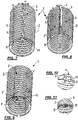
- FIG. 1 a perspective view of such a corrugated pipe immediately before attaching a longitudinal slot
- FIG. 2 a perspective view of the same corrugated pipe after attachment of the longitudinal slot 4
- FIG. 3 a perspective view of the same corrugated tube 1 is shown in the closed position, wherein in the closed position according to 3 the edge regions 5 and 6 of the corrugated pipe 1 lying on both sides of the longitudinal slot 4 (cf. 2 ) over a maximum overlap area a (in the circumferential direction).
- FIG. 1 shows the corrugated pipe 1 in the form that it has when it is produced after leaving the corrugator and immediately before it enters a cutting device.
- the corrugated pipe 1 is provided on its outside with circumferential waves 2, which consist of alternating successive wave crests and wave troughs running in the circumferential direction, but these waves 2 do not extend over the entire circumference, as does the Figures 1 and 2 show what is being referred to. Also provided within a certain circumferential area a' are circumferential corrugations 3 (with corrugation crests and corrugation troughs) which are fitted between the circumferentially opposite ends of the corrugations 2 and in their respective corresponding layers.
- the waves 3 within this specific peripheral area a' are offset from the waves 2, which cover the entire remaining circumference of the corrugated pipe 1, by a distance 8 radially towards the inside of the corrugated pipe 1, so that here, as the representations of FIG Figures 1 and 2 and in particular the enlarged representation of the detail A off 1 in 4 show, the radial underside of the wave troughs within this specific peripheral area a ' projects somewhat into the interior of the corrugated pipe 1.
- the radial distance 8 and the radial shoulder 7, both of which are of the same size, are selected in such a way that after the longitudinal slot 4 has been attached along a longitudinal surface line M - M (cf. Figures 1 and 2 ) Then, when the edge areas 5 and 6 of the corrugated pipe 1, which are on both sides of the longitudinal slot 4, are pressed together, the radial underside 9 of the corrugations 2 of the edge area 6 can be pushed over the radial top of the corrugations 3 of the other edge area 5, whereby the longitudinal slot 4 disappears and the edge regions 5 and 6 overlap.
- the transition between the waves 2 and 3 is geometrically identical is formed as at the opposite end of the peripheral portion a as shown in FIGS Figures 1 to 3 shown on the left is: Also at the transition between the corrugations 2 and 3 on the side of the specified peripheral area a of the corrugated pipe 1 facing the edge area 6, the corrugations 3 of the edge area 5 are radially lower around the radial step 7 than the corrugations 2 on the edge area 6, so that after the attachment of the Longitudinal slot 4 and with a complete covering of both edge areas 5, 6 to reach a closed position, as shown in 3 is shown, the result is an external shape for the corrugated tube 1 which shows no radial step in the circumferential direction.
- this is provided with a soft layer 10 on its entire inside (cf. also figure 5 as an enlarged representation of the detail B in 2 ), so that after the longitudinal slit 4 has been attached, the entire radial inner slit edge of the cut surfaces on both sides of the longitudinal slit 4 is formed by a soft material, so that the radial inner edges on the projections 8 are also made of a soft material.
- the embodiment of the corrugated tube 1, as in the Figures 7 to 11 is shown differs from that from the Figures 1 to 6 in that the entire inner surface of the corrugated pipe 1 is not lined with a layer of softer material, but rather that the corrugated pipe 1 when it exits the corrugator is provided with a longitudinal strip 11 running in the longitudinal direction of the corrugated pipe 1 and made of a softer thermoplastic material than the rest of the material of the Corrugated pipe 1 is provided, but which runs over the entire radial wall thickness of the corrugated pipe 1.
- this longitudinal strip 11 made of softer material is arranged along the longitudinal generating line M - M in such a way that it extends on both sides of the longitudinal generating line M - M .
- the longitudinal strip 4 is introduced into the corrugated pipe 1, the cut is placed so that the edge region 6 facing the cut edge of the longitudinal slot 4 coincides exactly with the end edge of the strip 11 lying there and thus, as a comparison of the Figures 7 and 8 shows that the cut edge of the longitudinal strip 4 there runs within the end section of the edge region 6, so that after the cut has been made at the cut edge there is no longer any soft material at this end of the edge region 6.
- the opposite section surface of the longitudinal section 4 runs, as can be seen particularly well from the enlarged representation of the detail D in 10 visible, still within the area of softer material, so that at the local end of the edge area 5, the entire cutting plane of the longitudinal section 4 is within the soft area, which is why, how 10 shows, at the end of the edge area 5 there (with the waves 3, which are radially somewhat recessed), a soft residual section 12 remains.
- the entire cut surface of the longitudinal slit 4 is there in the soft material and is therefore also completely formed by this soft material.
- the width b of the longitudinal slit 4 is smaller than the width of the strip 11 of softer material, which ensures that after the slitting process has been carried out, a small end section 12 made of softer material (cf. 10 ).
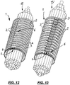
- corrugated tube 1 shows a corrugated pipe 1, which is provided neither with a soft inner layer 10, nor with a longitudinal strip 11 made of softer material, but was made only from a thermoplastic material.
- a plastic tube is first extruded from an extruder and then given a final shape in a downstream corrugator brought as they are shown 1 (However, without an inner soft layer 10).
- a longitudinal slot 4 (in the Figures 12 and 13 only covertly present) introduced and correspondingly with a subsequent thermal deformation in a closed position 3 or also according to the representation of 12 brought, in which the edge regions 5, 6 completely overlap radially over the entire peripheral region a .
- the corrugated tube 1 is from its initial state, as it is Figures 3 or 9 or 12 corresponds, by means of a suitable device so far spread or opened that the longitudinal slot 4 is opened, through which the cable 15 can then be introduced into the interior of the corrugated tube 1.
- the corrugated pipe 1 which corresponds to the due to the thermal deformation in its maximum closed position Figures 3 or 9 or 12 is elastically pretensioned, folded back into its closed position by the elastic pretension, as shown in 12 is shown.
- the edge regions 5 and 6 can no longer spring back up to the point in 12 shown maximum overlap, but there is a shorter, only partial overlap of both edge areas 5, 6 instead, as shown in 13 is shown.
- the corrugated pipe 1 can also accommodate cable bundles that have a larger nominal diameter than that of the maximum closed position (corresponding to 3 or 9 or 12 ) results, correspond, can accommodate and not about another corrugated pipe with a larger output diameter must be used for this.
- thermoplastic material can be used for the formation of the corrugated pipe 1, with polypropylene (PP) or a polyamide (PA) in particular being the harder material. with a Shore D hardness (according to ISO 868) greater than 60 and as a softer material, e.g. B. a thermoplastic elastomer (TPE) with a Shore A hardness of less than 80 are recommended.
- PP polypropylene
- PA polyamide
- TPE thermoplastic elastomer
- a plastic tube 21 is first extruded from an injection molding tool (extrusion head) 20 and then fed to a downstream corrugator 22 of a known type, in which the plastic tube 21 is provided in the desired manner with circumferential corrugations.
- a first extruder 17 and a second extruder 18 are connected to the extrusion tool 20, the first extruder 17 using a suitable thermoplastic material, such as a polypropylene or a polyamide with a Shore D hardness greater than 60, and the second extruder 18 using a thermoplastic Elastomer, which is softer and has a Shore A hardness of less than 80, the spray head 20 feeds.
- the corrugated plastic pipe 1 then emerges from the corrugator 22, which is provided with a longitudinal slit along a lateral line in a subsequent cutting device 23 and then fed to a device 24 for thermal deformation, preferably an IR deformation system, in which the slit corrugated pipe is placed on a temperature below the melting temperature of the thermoplastic material used and is then gradually converted into a final shape during a passage through deformation rollers, in which the edge regions 5, 6 on both sides of the longitudinal slot 4 are brought into a radial overlap in the circumferential direction until finally an overlapping position is reached , in which a complete overlapping of the area of radially lower-lying waves at one edge area has taken place through the radially higher-lying waves at the other edge area.
- a device 24 for thermal deformation preferably an IR deformation system
- the slit corrugated pipe is placed on a temperature below the melting temperature of the thermoplastic material used and is then gradually converted into a final shape during a passage through deformation rollers, in
- the corrugated tube 1 from the IR-forming system 24 is fed to a downstream cooling system 25 with a suitable cooling bath, after which the corrugated tube 1 is wound up or deposited in sections separated from one another.
- a plastic tube is extruded, which has a strip-shaped longitudinal section 11 made of a second, different thermoplastic material
- this can in Coextrusion takes place, for example, in that a torpedo insert is mounted centrally in the extrusion head of the extruder 17, which acts as a displacement body and forms the melt that occurs from the extruder 17 into an annular tube or hose 21.
- thermoplastic material (somewhat softer material) is introduced radially from the side into the flow of the melt circulating the torpedo via a lateral feed channel and is coextruded with it, as a result of which a strip of this other material is present along the extruded plastic tube 21 and then in the downstream corrugator 22 the desired formation with waves can take place over the circumference.
- This comprises a nozzle body 16 in which a torpedo 19 is arranged, which serves as a displacement body as the plastic melt 17', which is supplied by the first extruder 17 and represents the main material flow, passes through, in order to force the plastic melt (arrow S) emerging from the extrusion head 20 to form an annular tube 21.
- the second extruder 18 presses a plastic melt 18' made of a softer material via a feed channel 26 on the extruder head 20 into the main material flow of the plastic melt 17' displaced radially outwards by the torpedo 19.
- the two plastic melts 17' and 18' selected to be compatible with one another are combined and react chemically in such a way that a longitudinal strip of softer material is formed along the extruded tube 21, but is firmly connected to the harder material of the rest of the tube 21.
Landscapes
- Engineering & Computer Science (AREA)
- Mechanical Engineering (AREA)
- Physics & Mathematics (AREA)
- Manufacturing & Machinery (AREA)
- Architecture (AREA)
- Structural Engineering (AREA)
- Civil Engineering (AREA)
- Electromagnetism (AREA)
- General Engineering & Computer Science (AREA)
- Spectroscopy & Molecular Physics (AREA)
- Toxicology (AREA)
- Health & Medical Sciences (AREA)
- Rigid Pipes And Flexible Pipes (AREA)
- Extrusion Moulding Of Plastics Or The Like (AREA)
- Details Of Indoor Wiring (AREA)
- Shaping Of Tube Ends By Bending Or Straightening (AREA)
- Diaphragms And Bellows (AREA)
Applications Claiming Priority (2)
| Application Number | Priority Date | Filing Date | Title |
|---|---|---|---|
| DE102014108757.7A DE102014108757A1 (de) | 2014-06-23 | 2014-06-23 | Wellrohr aus Kunststoff zum Ummanteln von Leitungen sowie Verfahren zur Herstellung eines solchen Wellrohres |
| PCT/EP2015/061018 WO2015197266A1 (de) | 2014-06-23 | 2015-05-19 | Wellrohr aus kunststoff zum ummanteln von leitungen sowie verfahren zur herstellung eines solchen wellrohres |
Publications (2)
| Publication Number | Publication Date |
|---|---|
| EP3158614A1 EP3158614A1 (de) | 2017-04-26 |
| EP3158614B1 true EP3158614B1 (de) | 2022-04-20 |
Family
ID=53199987
Family Applications (1)
| Application Number | Title | Priority Date | Filing Date |
|---|---|---|---|
| EP15723939.3A Active EP3158614B1 (de) | 2014-06-23 | 2015-05-19 | Wellrohr aus kunststoff zum ummanteln von leitungen sowie verfahren zur herstellung eines solchen wellrohres |
Country Status (6)
| Country | Link |
|---|---|
| US (1) | US10199811B2 (enExample) |
| EP (1) | EP3158614B1 (enExample) |
| CN (1) | CN106663929B (enExample) |
| BR (1) | BR112016030238B1 (enExample) |
| DE (1) | DE102014108757A1 (enExample) |
| WO (1) | WO2015197266A1 (enExample) |
Families Citing this family (16)
| Publication number | Priority date | Publication date | Assignee | Title |
|---|---|---|---|---|
| US8864017B2 (en) | 2011-10-13 | 2014-10-21 | Orbis Corporation | Plastic corrugated container with improved fold lines and method and apparatus for making same |
| WO2015100249A2 (en) | 2013-12-24 | 2015-07-02 | Orbis Corporation | Plastic corrugated container and manufacturing process |
| US11643242B2 (en) | 2013-12-24 | 2023-05-09 | Orbis Corporation | Air vent for welded portion in plastic corrugated material, and process for forming welded portion |
| US10625916B2 (en) | 2013-12-24 | 2020-04-21 | Orbis Corporation | Plastic corrugated container with soft score line |
| DE102016220170A1 (de) * | 2016-10-14 | 2018-04-19 | Leoni Kabel Gmbh | Kabelsatz und Verfahren zur Herstellung eines Kabelsatzes |
| DE102016220167A1 (de) * | 2016-10-14 | 2018-04-19 | Leoni Kabel Gmbh | Kabelsatz und Verfahren zur Herstellung eines Kabelsatzes |
| DE102016123040A1 (de) * | 2016-11-29 | 2018-05-30 | Schlemmer Gmbh | Aufklappbarer Wellschlauch und Kabelbaum |
| CA3052706C (en) | 2017-02-21 | 2024-01-09 | Menasha Corporation | Straight consistent body scores on plastic corrugated boxes and a process for making same |
| DE102017105807B3 (de) * | 2017-03-17 | 2018-08-16 | Schlemmer Holding GmbH | Mehrkomponenten-Extrusionsspritzkopf, Mehrkomponenten-Extrusionsanlage und Verfahren zum Herstellen eines Verbundschlauchs |
| CN106992477B (zh) * | 2017-05-12 | 2019-03-26 | 深圳市骏鼎达新材料股份有限公司 | 一种平滑锁合式波纹管及其制造方法 |
| CN107013766A (zh) * | 2017-05-25 | 2017-08-04 | 江苏省埃迪机电设备实业有限公司 | 一种波形为波浪形的金属波纹管 |
| US11072140B2 (en) * | 2017-06-20 | 2021-07-27 | Orbis Corporation | Balanced process for extrusion of plastic corrugated sheet and subsequent converting into plastic boxes |
| CN109900389B (zh) * | 2019-03-14 | 2020-11-03 | 中北大学 | 一种灌浆套筒浆料温度测量装置及其测量方法 |
| JP7019272B2 (ja) * | 2019-06-07 | 2022-02-15 | 矢崎総業株式会社 | コルゲートチューブ及びワイヤハーネス |
| CN112590154A (zh) * | 2020-12-04 | 2021-04-02 | 长春百思特汽车零部件有限公司 | 一种波纹管的生产方法、生产装置及波纹管 |
| JP7587552B2 (ja) * | 2022-06-30 | 2024-11-20 | 矢崎総業株式会社 | 外装材、外装材連結体、ワイヤハーネス、及びワイヤハーネスの製造方法 |
Family Cites Families (26)
| Publication number | Priority date | Publication date | Assignee | Title |
|---|---|---|---|---|
| US3336950A (en) * | 1964-05-19 | 1967-08-22 | Continental Oil Co | Culvert construction |
| DE3246594A1 (de) | 1982-12-16 | 1984-06-20 | Hegler, Wilhelm, 8730 Bad Kissingen | Huellwellrohr |
| DE3405552C2 (de) | 1984-02-16 | 1986-02-27 | Fränkische Rohrwerke Gebrüder Kirchner GmbH & Co, 8729 Königsberg | Kunststoff-Schutzrohr |
| US4766662A (en) * | 1984-08-15 | 1988-08-30 | Dayco Products, Inc. | Method of protecting hose with a plastic abrasion-resistant protective sleeve |
| DE3640226A1 (de) * | 1986-11-25 | 1988-06-01 | Kirchner Fraenk Rohr | Kunststoff-schutzrohranordnung fuer leitungen |
| FR2615332A1 (fr) | 1987-05-15 | 1988-11-18 | Plastic Omnium Cie | Tube profile en matiere plastique |
| BR9207176A (pt) | 1992-11-17 | 1995-12-19 | Proprietary Technology Inc | Tubulação corrugada fendida de travamento automático |
| US5566722A (en) * | 1992-11-17 | 1996-10-22 | Proprietary Technology, Inc. | Self locking slitted corrugated tubing |
| FR2745429B1 (fr) * | 1996-02-28 | 1998-04-17 | Sofanou Sa | Gaine annelee fendue |
| CN1075619C (zh) * | 1996-09-03 | 2001-11-28 | 住友电装株式会社 | 一种波纹管、一种自动导线装载方法和装置 |
| DE19641421C2 (de) | 1996-10-08 | 1999-07-08 | Schlemmer & Co Josef | Wellrohr zur schützenden Ummantelung elektrischer Leitungen |
| DE19700916A1 (de) | 1997-01-14 | 1998-07-16 | Ralph Peter Dr Ing Hegler | Einteiliges Hüll-Wellrohr und Verfahren zu seiner Herstellung |
| DE19705761A1 (de) | 1997-02-14 | 1998-08-20 | Kirchner Fraenk Rohr | Kunststoffwellrohr |
| CN1198031A (zh) | 1997-02-21 | 1998-11-04 | 住友电装株式会社 | 波纹管 |
| GB2336475B (en) * | 1998-04-18 | 2002-05-08 | T & N Technology Ltd | Flexible protective sleeve |
| DE19904977A1 (de) * | 1999-02-06 | 2000-08-10 | Ralph Peter Hegler | Verfahren zur Herstellung eines einteiligen Hüll-Wellrohres aus thermoplastischem Kunststoff und Verfahren zum Einlegen mindestens einer elektrischen Leitung in ein solches Hüll-Wellrohr |
| JP3949396B2 (ja) * | 2001-06-12 | 2007-07-25 | 矢崎総業株式会社 | コルゲートチューブ |
| JP3883398B2 (ja) * | 2001-06-12 | 2007-02-21 | 矢崎総業株式会社 | コルゲートチューブ及びその形成方法 |
| JP2003079021A (ja) * | 2001-08-31 | 2003-03-14 | Yazaki Corp | コルゲートチューブ及びその形成方法 |
| FR2832487B1 (fr) * | 2001-11-21 | 2004-02-13 | Fed Mogul Systems Prot Group | Gaine de protection pour tube de circulation de fluide |
| JP2006005983A (ja) * | 2004-06-15 | 2006-01-05 | Yazaki Corp | コルゲートチューブ |
| FR2903475B1 (fr) * | 2006-07-05 | 2011-10-21 | Sofanou Sa | Gaine tubulaire annelee de protection comprenant une charniere et dispositif pour fabriquer une telle gaine |
| EP2182599B1 (de) | 2008-10-30 | 2016-10-19 | Schlemmer Gmbh | Wellrohr aus Kunststoff, insbesondere zum Ummanteln elektrischer Leitungen |
| JP5798775B2 (ja) * | 2011-04-04 | 2015-10-21 | 矢崎総業株式会社 | コルゲートチューブ |
| US9478954B2 (en) * | 2012-04-11 | 2016-10-25 | Federal-Mogul Powertrain, Inc. | Self-curling non-woven sleeve and method of construction thereof |
| DE102015112272B4 (de) * | 2015-07-27 | 2020-12-17 | Schlemmer Gmbh | Aufklappbarer Wellschlauch, Kabelbaum und Verfahren zum Herstellen eines derartigen aufklappbaren Wellschlauchs |
-
2014
- 2014-06-23 DE DE102014108757.7A patent/DE102014108757A1/de active Pending
-
2015
- 2015-05-19 EP EP15723939.3A patent/EP3158614B1/de active Active
- 2015-05-19 CN CN201580034396.4A patent/CN106663929B/zh active Active
- 2015-05-19 BR BR112016030238-9A patent/BR112016030238B1/pt active IP Right Grant
- 2015-05-19 WO PCT/EP2015/061018 patent/WO2015197266A1/de not_active Ceased
- 2015-05-19 US US15/321,720 patent/US10199811B2/en active Active
Also Published As
| Publication number | Publication date |
|---|---|
| CN106663929A (zh) | 2017-05-10 |
| BR112016030238A2 (enExample) | 2017-08-22 |
| US20170141553A1 (en) | 2017-05-18 |
| DE102014108757A1 (de) | 2015-12-24 |
| EP3158614A1 (de) | 2017-04-26 |
| CN106663929B (zh) | 2019-03-29 |
| WO2015197266A1 (de) | 2015-12-30 |
| US10199811B2 (en) | 2019-02-05 |
| BR112016030238B1 (pt) | 2022-09-20 |
Similar Documents
| Publication | Publication Date | Title |
|---|---|---|
| EP3158614B1 (de) | Wellrohr aus kunststoff zum ummanteln von leitungen sowie verfahren zur herstellung eines solchen wellrohres | |
| DE1525815B1 (de) | Laenglicher gegebenenfalls verzweigter rohr oder schlauch foermiger huellmantel aus thermoplastischem kunststoff oder dergl | |
| EP0835543B1 (de) | Flexible schlauchhülle | |
| DE19700916A1 (de) | Einteiliges Hüll-Wellrohr und Verfahren zu seiner Herstellung | |
| EP3218972A1 (de) | Wellrohranordnung zur aufnahme von leitungen und verfahren zur herstellung einer solchen wellrohranordnung | |
| EP1188013B1 (de) | Verfahren zur herstellung eines wellrohres mit einer längs einer mantellinie verlaufenden schlitzförmigen öffnung | |
| DE3405552C2 (de) | Kunststoff-Schutzrohr | |
| DE19747623C2 (de) | Wellrohr zur schützenden Ummantelung elektrischer Leitungen | |
| EP3271980B1 (de) | Wellrohr aus kunststoff zum ummanteln von leitungen | |
| EP1138102B1 (de) | Verfahren zur herstellung eines einteiligen hüll-wellrohres | |
| EP0226940A2 (de) | Schrumpfbare Kabelmuffe | |
| DE19716232A1 (de) | Flexible Schlauchhülle | |
| DE102016119604A1 (de) | Kabelummantelung und Kabelbaum | |
| DE102019111083B4 (de) | Schutzband, umwickeltes Kabelbündel und Verfahren | |
| DE102007018915B4 (de) | Stützwendel mit mechanischer Verriegelung und Verfahren zu deren Herstellung | |
| EP2985133B1 (de) | Verfahren zur nachumhüllung eines rohrformteils | |
| DE19725811A1 (de) | Wellrohrweiche | |
| DE19837592C1 (de) | Verfahren zur Herstellung einer Schutzhülle | |
| DE29719158U1 (de) | Wellrohr zur schützenden Ummantelung elektrischer Leitungen | |
| WO1998021793A1 (de) | Flexible schlauchhülle | |
| DE3038922A1 (de) | Schlauchfoermige garnitur fuer elektrische kabel und rohrleitungen und verfahren zu ihrer herstellung | |
| EP1214767B1 (de) | Schutzumhüllung für elektrische leitungen und verfahren zur herstellung einer solchen schutzumhüllung | |
| EP2146412A2 (de) | Schrumpfschlauch | |
| DE8427762U1 (de) | Rohrförmige Isolierschale zur thermischen Isolation an Rohrleitungen von Wärme- oder Kälteanlagen | |
| CH699570A1 (de) | Verfahren zur Herstellung eines wärmeisolierten Leitungsrohres sowie wärmeisoliertes Leitungsrohr. |
Legal Events
| Date | Code | Title | Description |
|---|---|---|---|
| STAA | Information on the status of an ep patent application or granted ep patent |
Free format text: STATUS: THE INTERNATIONAL PUBLICATION HAS BEEN MADE |
|
| PUAI | Public reference made under article 153(3) epc to a published international application that has entered the european phase |
Free format text: ORIGINAL CODE: 0009012 |
|
| STAA | Information on the status of an ep patent application or granted ep patent |
Free format text: STATUS: REQUEST FOR EXAMINATION WAS MADE |
|
| 17P | Request for examination filed |
Effective date: 20170113 |
|
| AK | Designated contracting states |
Kind code of ref document: A1 Designated state(s): AL AT BE BG CH CY CZ DE DK EE ES FI FR GB GR HR HU IE IS IT LI LT LU LV MC MK MT NL NO PL PT RO RS SE SI SK SM TR |
|
| AX | Request for extension of the european patent |
Extension state: BA ME |
|
| DAV | Request for validation of the european patent (deleted) | ||
| DAX | Request for extension of the european patent (deleted) | ||
| STAA | Information on the status of an ep patent application or granted ep patent |
Free format text: STATUS: EXAMINATION IS IN PROGRESS |
|
| 17Q | First examination report despatched |
Effective date: 20190724 |
|
| GRAP | Despatch of communication of intention to grant a patent |
Free format text: ORIGINAL CODE: EPIDOSNIGR1 |
|
| STAA | Information on the status of an ep patent application or granted ep patent |
Free format text: STATUS: GRANT OF PATENT IS INTENDED |
|
| RIC1 | Information provided on ipc code assigned before grant |
Ipc: H02G 3/04 20060101AFI20210611BHEP Ipc: H01B 3/44 20060101ALI20210611BHEP Ipc: B29C 48/09 20190101ALI20210611BHEP Ipc: B29C 48/13 20190101ALI20210611BHEP Ipc: B29C 48/00 20190101ALI20210611BHEP Ipc: B29C 48/21 20190101ALI20210611BHEP Ipc: B29C 48/30 20190101ALI20210611BHEP |
|
| INTG | Intention to grant announced |
Effective date: 20210708 |
|
| 19U | Interruption of proceedings before grant |
Effective date: 20200301 |
|
| 19W | Proceedings resumed before grant after interruption of proceedings |
Effective date: 20220103 |
|
| GRAS | Grant fee paid |
Free format text: ORIGINAL CODE: EPIDOSNIGR3 |
|
| RAP3 | Party data changed (applicant data changed or rights of an application transferred) |
Owner name: DELFINGEN FR-ANTEUIL S.A. |
|
| GRAA | (expected) grant |
Free format text: ORIGINAL CODE: 0009210 |
|
| STAA | Information on the status of an ep patent application or granted ep patent |
Free format text: STATUS: THE PATENT HAS BEEN GRANTED |
|
| AK | Designated contracting states |
Kind code of ref document: B1 Designated state(s): AL AT BE BG CH CY CZ DE DK EE ES FI FR GB GR HR HU IE IS IT LI LT LU LV MC MK MT NL NO PL PT RO RS SE SI SK SM TR |
|
| REG | Reference to a national code |
Ref country code: GB Ref legal event code: FG4D Free format text: NOT ENGLISH |
|
| REG | Reference to a national code |
Ref country code: CH Ref legal event code: EP |
|
| REG | Reference to a national code |
Ref country code: DE Ref legal event code: R096 Ref document number: 502015015780 Country of ref document: DE |
|
| REG | Reference to a national code |
Ref country code: IE Ref legal event code: FG4D Free format text: LANGUAGE OF EP DOCUMENT: GERMAN |
|
| REG | Reference to a national code |
Ref country code: AT Ref legal event code: REF Ref document number: 1485947 Country of ref document: AT Kind code of ref document: T Effective date: 20220515 |
|
| REG | Reference to a national code |
Ref country code: LT Ref legal event code: MG9D |
|
| REG | Reference to a national code |
Ref country code: NL Ref legal event code: MP Effective date: 20220420 |
|
| PG25 | Lapsed in a contracting state [announced via postgrant information from national office to epo] |
Ref country code: NL Free format text: LAPSE BECAUSE OF FAILURE TO SUBMIT A TRANSLATION OF THE DESCRIPTION OR TO PAY THE FEE WITHIN THE PRESCRIBED TIME-LIMIT Effective date: 20220420 |
|
| PG25 | Lapsed in a contracting state [announced via postgrant information from national office to epo] |
Ref country code: SE Free format text: LAPSE BECAUSE OF FAILURE TO SUBMIT A TRANSLATION OF THE DESCRIPTION OR TO PAY THE FEE WITHIN THE PRESCRIBED TIME-LIMIT Effective date: 20220420 Ref country code: PT Free format text: LAPSE BECAUSE OF FAILURE TO SUBMIT A TRANSLATION OF THE DESCRIPTION OR TO PAY THE FEE WITHIN THE PRESCRIBED TIME-LIMIT Effective date: 20220822 Ref country code: NO Free format text: LAPSE BECAUSE OF FAILURE TO SUBMIT A TRANSLATION OF THE DESCRIPTION OR TO PAY THE FEE WITHIN THE PRESCRIBED TIME-LIMIT Effective date: 20220720 Ref country code: LT Free format text: LAPSE BECAUSE OF FAILURE TO SUBMIT A TRANSLATION OF THE DESCRIPTION OR TO PAY THE FEE WITHIN THE PRESCRIBED TIME-LIMIT Effective date: 20220420 Ref country code: HR Free format text: LAPSE BECAUSE OF FAILURE TO SUBMIT A TRANSLATION OF THE DESCRIPTION OR TO PAY THE FEE WITHIN THE PRESCRIBED TIME-LIMIT Effective date: 20220420 Ref country code: GR Free format text: LAPSE BECAUSE OF FAILURE TO SUBMIT A TRANSLATION OF THE DESCRIPTION OR TO PAY THE FEE WITHIN THE PRESCRIBED TIME-LIMIT Effective date: 20220721 Ref country code: FI Free format text: LAPSE BECAUSE OF FAILURE TO SUBMIT A TRANSLATION OF THE DESCRIPTION OR TO PAY THE FEE WITHIN THE PRESCRIBED TIME-LIMIT Effective date: 20220420 Ref country code: ES Free format text: LAPSE BECAUSE OF FAILURE TO SUBMIT A TRANSLATION OF THE DESCRIPTION OR TO PAY THE FEE WITHIN THE PRESCRIBED TIME-LIMIT Effective date: 20220420 Ref country code: BG Free format text: LAPSE BECAUSE OF FAILURE TO SUBMIT A TRANSLATION OF THE DESCRIPTION OR TO PAY THE FEE WITHIN THE PRESCRIBED TIME-LIMIT Effective date: 20220720 |
|
| PG25 | Lapsed in a contracting state [announced via postgrant information from national office to epo] |
Ref country code: RS Free format text: LAPSE BECAUSE OF FAILURE TO SUBMIT A TRANSLATION OF THE DESCRIPTION OR TO PAY THE FEE WITHIN THE PRESCRIBED TIME-LIMIT Effective date: 20220420 Ref country code: PL Free format text: LAPSE BECAUSE OF FAILURE TO SUBMIT A TRANSLATION OF THE DESCRIPTION OR TO PAY THE FEE WITHIN THE PRESCRIBED TIME-LIMIT Effective date: 20220420 Ref country code: LV Free format text: LAPSE BECAUSE OF FAILURE TO SUBMIT A TRANSLATION OF THE DESCRIPTION OR TO PAY THE FEE WITHIN THE PRESCRIBED TIME-LIMIT Effective date: 20220420 Ref country code: IS Free format text: LAPSE BECAUSE OF FAILURE TO SUBMIT A TRANSLATION OF THE DESCRIPTION OR TO PAY THE FEE WITHIN THE PRESCRIBED TIME-LIMIT Effective date: 20220820 |
|
| REG | Reference to a national code |
Ref country code: CH Ref legal event code: PL |
|
| REG | Reference to a national code |
Ref country code: DE Ref legal event code: R097 Ref document number: 502015015780 Country of ref document: DE |
|
| REG | Reference to a national code |
Ref country code: BE Ref legal event code: MM Effective date: 20220531 |
|
| PG25 | Lapsed in a contracting state [announced via postgrant information from national office to epo] |
Ref country code: SM Free format text: LAPSE BECAUSE OF FAILURE TO SUBMIT A TRANSLATION OF THE DESCRIPTION OR TO PAY THE FEE WITHIN THE PRESCRIBED TIME-LIMIT Effective date: 20220420 Ref country code: SK Free format text: LAPSE BECAUSE OF FAILURE TO SUBMIT A TRANSLATION OF THE DESCRIPTION OR TO PAY THE FEE WITHIN THE PRESCRIBED TIME-LIMIT Effective date: 20220420 Ref country code: RO Free format text: LAPSE BECAUSE OF FAILURE TO SUBMIT A TRANSLATION OF THE DESCRIPTION OR TO PAY THE FEE WITHIN THE PRESCRIBED TIME-LIMIT Effective date: 20220420 Ref country code: MC Free format text: LAPSE BECAUSE OF FAILURE TO SUBMIT A TRANSLATION OF THE DESCRIPTION OR TO PAY THE FEE WITHIN THE PRESCRIBED TIME-LIMIT Effective date: 20220420 Ref country code: LU Free format text: LAPSE BECAUSE OF NON-PAYMENT OF DUE FEES Effective date: 20220519 Ref country code: LI Free format text: LAPSE BECAUSE OF NON-PAYMENT OF DUE FEES Effective date: 20220531 Ref country code: EE Free format text: LAPSE BECAUSE OF FAILURE TO SUBMIT A TRANSLATION OF THE DESCRIPTION OR TO PAY THE FEE WITHIN THE PRESCRIBED TIME-LIMIT Effective date: 20220420 Ref country code: DK Free format text: LAPSE BECAUSE OF FAILURE TO SUBMIT A TRANSLATION OF THE DESCRIPTION OR TO PAY THE FEE WITHIN THE PRESCRIBED TIME-LIMIT Effective date: 20220420 Ref country code: CZ Free format text: LAPSE BECAUSE OF FAILURE TO SUBMIT A TRANSLATION OF THE DESCRIPTION OR TO PAY THE FEE WITHIN THE PRESCRIBED TIME-LIMIT Effective date: 20220420 Ref country code: CH Free format text: LAPSE BECAUSE OF NON-PAYMENT OF DUE FEES Effective date: 20220531 |
|
| PLBE | No opposition filed within time limit |
Free format text: ORIGINAL CODE: 0009261 |
|
| STAA | Information on the status of an ep patent application or granted ep patent |
Free format text: STATUS: NO OPPOSITION FILED WITHIN TIME LIMIT |
|
| 26N | No opposition filed |
Effective date: 20230123 |
|
| GBPC | Gb: european patent ceased through non-payment of renewal fee |
Effective date: 20220720 |
|
| PG25 | Lapsed in a contracting state [announced via postgrant information from national office to epo] |
Ref country code: AL Free format text: LAPSE BECAUSE OF FAILURE TO SUBMIT A TRANSLATION OF THE DESCRIPTION OR TO PAY THE FEE WITHIN THE PRESCRIBED TIME-LIMIT Effective date: 20220420 |
|
| PG25 | Lapsed in a contracting state [announced via postgrant information from national office to epo] |
Ref country code: IE Free format text: LAPSE BECAUSE OF NON-PAYMENT OF DUE FEES Effective date: 20220519 |
|
| PG25 | Lapsed in a contracting state [announced via postgrant information from national office to epo] |
Ref country code: SI Free format text: LAPSE BECAUSE OF FAILURE TO SUBMIT A TRANSLATION OF THE DESCRIPTION OR TO PAY THE FEE WITHIN THE PRESCRIBED TIME-LIMIT Effective date: 20220420 Ref country code: GB Free format text: LAPSE BECAUSE OF NON-PAYMENT OF DUE FEES Effective date: 20220720 Ref country code: BE Free format text: LAPSE BECAUSE OF NON-PAYMENT OF DUE FEES Effective date: 20220531 |
|
| REG | Reference to a national code |
Ref country code: AT Ref legal event code: MM01 Ref document number: 1485947 Country of ref document: AT Kind code of ref document: T Effective date: 20220519 |
|
| PG25 | Lapsed in a contracting state [announced via postgrant information from national office to epo] |
Ref country code: AT Free format text: LAPSE BECAUSE OF NON-PAYMENT OF DUE FEES Effective date: 20220519 |
|
| PGFP | Annual fee paid to national office [announced via postgrant information from national office to epo] |
Ref country code: DE Payment date: 20230522 Year of fee payment: 9 |
|
| PG25 | Lapsed in a contracting state [announced via postgrant information from national office to epo] |
Ref country code: HU Free format text: LAPSE BECAUSE OF FAILURE TO SUBMIT A TRANSLATION OF THE DESCRIPTION OR TO PAY THE FEE WITHIN THE PRESCRIBED TIME-LIMIT; INVALID AB INITIO Effective date: 20150519 |
|
| PG25 | Lapsed in a contracting state [announced via postgrant information from national office to epo] |
Ref country code: MK Free format text: LAPSE BECAUSE OF FAILURE TO SUBMIT A TRANSLATION OF THE DESCRIPTION OR TO PAY THE FEE WITHIN THE PRESCRIBED TIME-LIMIT Effective date: 20220420 Ref country code: CY Free format text: LAPSE BECAUSE OF FAILURE TO SUBMIT A TRANSLATION OF THE DESCRIPTION OR TO PAY THE FEE WITHIN THE PRESCRIBED TIME-LIMIT Effective date: 20220420 |
|
| PG25 | Lapsed in a contracting state [announced via postgrant information from national office to epo] |
Ref country code: TR Free format text: LAPSE BECAUSE OF FAILURE TO SUBMIT A TRANSLATION OF THE DESCRIPTION OR TO PAY THE FEE WITHIN THE PRESCRIBED TIME-LIMIT Effective date: 20220420 |
|
| PGFP | Annual fee paid to national office [announced via postgrant information from national office to epo] |
Ref country code: FR Payment date: 20240522 Year of fee payment: 10 |
|
| PG25 | Lapsed in a contracting state [announced via postgrant information from national office to epo] |
Ref country code: MT Free format text: LAPSE BECAUSE OF FAILURE TO SUBMIT A TRANSLATION OF THE DESCRIPTION OR TO PAY THE FEE WITHIN THE PRESCRIBED TIME-LIMIT Effective date: 20220420 |
|
| PGFP | Annual fee paid to national office [announced via postgrant information from national office to epo] |
Ref country code: IT Payment date: 20240531 Year of fee payment: 10 |
|
| PG25 | Lapsed in a contracting state [announced via postgrant information from national office to epo] |
Ref country code: BG Free format text: LAPSE BECAUSE OF FAILURE TO SUBMIT A TRANSLATION OF THE DESCRIPTION OR TO PAY THE FEE WITHIN THE PRESCRIBED TIME-LIMIT Effective date: 20220420 |
|
| PG25 | Lapsed in a contracting state [announced via postgrant information from national office to epo] |
Ref country code: BG Free format text: LAPSE BECAUSE OF FAILURE TO SUBMIT A TRANSLATION OF THE DESCRIPTION OR TO PAY THE FEE WITHIN THE PRESCRIBED TIME-LIMIT Effective date: 20220420 |