EP3153763A1 - Sicherheitsschalter zum überwachen eines aus einem ortsfesten und einem bewegbaren teil bestehenden zugangs eines automatisierungssystems - Google Patents
Sicherheitsschalter zum überwachen eines aus einem ortsfesten und einem bewegbaren teil bestehenden zugangs eines automatisierungssystems Download PDFInfo
- Publication number
- EP3153763A1 EP3153763A1 EP16181792.9A EP16181792A EP3153763A1 EP 3153763 A1 EP3153763 A1 EP 3153763A1 EP 16181792 A EP16181792 A EP 16181792A EP 3153763 A1 EP3153763 A1 EP 3153763A1
- Authority
- EP
- European Patent Office
- Prior art keywords
- housing part
- access
- safety switch
- housing
- magnetic
- Prior art date
- Legal status (The legal status is an assumption and is not a legal conclusion. Google has not performed a legal analysis and makes no representation as to the accuracy of the status listed.)
- Granted
Links
Images
Classifications
-
- H—ELECTRICITY
- H01—ELECTRIC ELEMENTS
- H01H—ELECTRIC SWITCHES; RELAYS; SELECTORS; EMERGENCY PROTECTIVE DEVICES
- H01H50/00—Details of electromagnetic relays
- H01H50/02—Bases; Casings; Covers
- H01H50/04—Mounting complete relay or separate parts of relay on a base or inside a case
-
- E—FIXED CONSTRUCTIONS
- E05—LOCKS; KEYS; WINDOW OR DOOR FITTINGS; SAFES
- E05C—BOLTS OR FASTENING DEVICES FOR WINGS, SPECIALLY FOR DOORS OR WINDOWS
- E05C19/00—Other devices specially designed for securing wings, e.g. with suction cups
- E05C19/16—Devices holding the wing by magnetic or electromagnetic attraction
- E05C19/166—Devices holding the wing by magnetic or electromagnetic attraction electromagnetic
-
- E—FIXED CONSTRUCTIONS
- E05—LOCKS; KEYS; WINDOW OR DOOR FITTINGS; SAFES
- E05C—BOLTS OR FASTENING DEVICES FOR WINGS, SPECIALLY FOR DOORS OR WINDOWS
- E05C19/00—Other devices specially designed for securing wings, e.g. with suction cups
- E05C19/16—Devices holding the wing by magnetic or electromagnetic attraction
-
- F—MECHANICAL ENGINEERING; LIGHTING; HEATING; WEAPONS; BLASTING
- F16—ENGINEERING ELEMENTS AND UNITS; GENERAL MEASURES FOR PRODUCING AND MAINTAINING EFFECTIVE FUNCTIONING OF MACHINES OR INSTALLATIONS; THERMAL INSULATION IN GENERAL
- F16P—SAFETY DEVICES IN GENERAL; SAFETY DEVICES FOR PRESSES
- F16P3/00—Safety devices acting in conjunction with the control or operation of a machine; Control arrangements requiring the simultaneous use of two or more parts of the body
- F16P3/08—Safety devices acting in conjunction with the control or operation of a machine; Control arrangements requiring the simultaneous use of two or more parts of the body in connection with the locking of doors, covers, guards, or like members giving access to moving machine parts
-
- H—ELECTRICITY
- H01—ELECTRIC ELEMENTS
- H01F—MAGNETS; INDUCTANCES; TRANSFORMERS; SELECTION OF MATERIALS FOR THEIR MAGNETIC PROPERTIES
- H01F7/00—Magnets
- H01F7/02—Permanent magnets [PM]
- H01F7/0273—Magnetic circuits with PM for magnetic field generation
-
- H—ELECTRICITY
- H01—ELECTRIC ELEMENTS
- H01H—ELECTRIC SWITCHES; RELAYS; SELECTORS; EMERGENCY PROTECTIVE DEVICES
- H01H51/00—Electromagnetic relays
- H01H51/01—Relays in which the armature is maintained in one position by a permanent magnet and freed by energisation of a coil producing an opposing magnetic field
Definitions
- the present invention relates to a safety switch for monitoring an access of an automation system consisting of a stationary and a movable part.
- Such monitoring is realized on the one hand by electromechanical or on the other by non-contact safety switch.
- the safety switches used for this purpose comprise a sensor part, which is fixedly mounted on the stationary part of the access, and a transmitter part, which is mounted on the movable part of the access. When the access is closed, the transmitter part is located directly opposite the sensor part, so that the sensor part detect a signal from the transmitter part and, if necessary, as Enable signal to communicate with the PLC, so that the automation system can start.
- the transmitter part In the open state of the access, the transmitter part is at a distance from the sensor part, so that the sensor part can not detect a signal and also can not communicate a release signal to the PLC. As a result, the automation system is not released for operation or, if the automation system is already in operation, transferred to a safe state.
- a safety switch for monitoring an existing from a stationary and a movable part access an automation system
- the safety switch having a first housing part with an elongated, preferably cuboid, shape and a second housing part with a form-fitting to the first housing part shape in that the first housing part has a first magnet element and the second housing part has a second magnet element, the first housing part is fixed in the fixed part of the access and the second housing part is arranged in the movable part of the access, so that in a closed state of the access the magnetic elements are opposite, the magnetic elements are magnetically effective with each other, and a magnetic clamping force is measurable
- the first housing part a signal receiver and an evaluation unit and the second housing part having a signal generator or vice versa, and at a first end of the elongated shape of the first and the second housing part, the first and the second magnetic element is provided and at a second end of the elongated shape of the first and second housing part of the signal receiver or the signal generator is
- the first magnetic element comprises an electromagnet, a permanent magnet or a magnet armature.
- the second magnetic element advantageously comprises a magnet armature, an electromagnet or a permanent magnet.
- the signal generator in the closed state of access is arranged opposite the signal receiver and the evaluation unit receives a signal in this closed position.
- the automation system is located in an open state of access of the signal transmitter spaced from the signal receiver and the evaluation unit receives no signal in this open position, so that the automation system can be brought into a safe state.
- the magnetic holding force of the magnetic elements is designed smaller than a torque of the elongated first and second housing part, which consists of a weight force at the second end of the first and second housing part with the signal receiver and the evaluation unit and the signal generator and a lever arm from a distance between the second end of the first and the second housing part to the first end of the first and the second housing part forms with the respective magnetic elements.
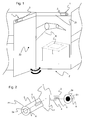
- FIG. 1 schematically an access Z to an automation system R is shown, which consists of a stationary part Z1 in the form of a wall or a protective fence and a movable part Z2 in the form of a door.
- the access Z serves to prevent an access of a person to the automation system R during operation or to bring the automation system R in a secure state with respect to the person.
- the stationary and movable part Z1 and Z2 of the access Z each have a finely wide frame, in each of which a housing part 2 and 3 of a safety switch 1 according to the invention is mounted, wherein the safety switch 1 according to the invention is provided to a closed or open state of access Z to monitor.
- the safety switch 1 is able to detect whether the access Z open, d. H. the movable part Z2 of the access Z is spaced from the fixed part Z1 of the access Z, or closed, i. the movable part Z2 of the access Z is located directly opposite the stationary part Z1 of the access Z.
- the safety switch 1 has a first and a second housing part 2 and 3, wherein the first and second housing part 2 and 3 each with an elongated, preferably cuboid, is provided form.
- the first and second housing part 2 and 3 are positively formed with each other.
- the first housing part 2 of the safety switch 1 is mounted as part of the stationary part Z1 of the access Z and the second housing part 3 of the safety switch 1 is mounted in the frame of the movable part Z2 of the access Z.
- the safety switch 1 and the housing parts 2 and 3 of the safety switch 1 no interference contour at the entrance Z, since the safety switch 1 and the housing parts 2 and 3 of the safety switch 1 is arranged so to speak integrated into the frame of the access Z or are.
- FIG. 2 shows a schematic view of the safety switch 1 according to the invention in detail, wherein the first and second housing part 2 and 3 are shown side by side for better understanding.
- the first housing part 2 has a first magnetic element 2a at a first end E1 of the elongate shape, wherein preferably the first magnetic element 2a comprises an electromagnet, a permanent magnet or a magnet armature. At a second end E 2 of the elongate shape, the first housing part 2 has a signal receiver 4 and an evaluation unit 6.
- the second housing part 3 has a second magnet element 3a at a first end E1 of the elongate shape, wherein the second magnet element 3a preferably also comprises an electromagnet, a permanent magnet or a magnet armature. At a second end E 2 of the elongated shape, the second housing part 3 has a signal generator 5.
- the second magnetic element 3a of the second housing part 3 comprises the magnet armature, or vice versa.
- the signal receiver 4 receives a signal from the signal generator 5, so that the evaluation unit 6 communicates a signal representing the closed state of the access Z, to a higher-level programmable logic controller PLC.
- the PLC can enable the operation of the automation system R on the basis of the signal of the evaluation unit 6.
- the safety switch 1 can have this functionality of the PLC, i. H. the evaluation unit 6 of the safety switch 1 releases the operation of the automation system R when the access Z is closed, or leads the automation system R in a safe state when the access Z is open or is opened.
- the first and second housing parts 2 and 3 of the safety switch 1 each have a longitudinal axis A, which extends along the elongated shape of the first and the second housing part 2 and 3.
- first and second housing parts 2 and 3 are arranged in such a way in the stationary and movable parts Z1 and Z2 of the access Z, that the longitudinal axis A of the first and second housing parts 2 and 3 is in a horizontal position. That is, the elongated shape of the first and second housing parts 2 and 3 are each mounted horizontally in the frame of the access Z.
- first and second housing parts 2 and 3 of the safety switch 1 engages at both first and second ends E1 and E2 of the first and second housing parts 2 and 3 in each case a gravitational force.
- the weight force is compensated by the frame of the access Z.
- the magnetic holding force of the first and second magnetic elements 2a and 3a is made smaller than a torque of the elongated first and second housing parts 2 and 3, the torque being the weight force at the second end E2 of the first and second housing parts 2 and 3, respectively with the signal receiver 4 and the evaluation unit 6 and the signal generator 5 and a lever arm from a distance between the second end E2 of the first and second housing part 2 and 3 to the first end E1 of the first and second housing part 2 and 3, respectively forms the respective magnetic element 2a and 3a.
- the two housing parts 2 and 3 are held by the magnetic clamping force at the first end E1 of the first and second housing parts 2 and 3 to each other.
- the existing torque at the second end E2 of mounted without on the frame of the access Z housing part 3 and 2 of the safety switch 1 causes a rotation of the housing part 3 and 2 relative to the horizontal position and with respect to the frame mounted housing part 2 and 3 of the safety switch 1 in a vertical position of the longitudinal axis of the mounted without on the frame of the access Z housing part 3 and 2 respectively.
- the signal generator 5 moves in the mounted without attached to the frame of the access Z housing part 3 and 2 of the signal receiver 4 of the stationary frame of the access Z mounted housing part 2 and 3, so that no signal can be received.
- the evaluation unit 6 therefore determines an open state of the access Z, although with the attachment of the mounted without the frame of the access Z housing part 3 or 2, a closed state of the access Z should be manipulated.
Landscapes
- Physics & Mathematics (AREA)
- Electromagnetism (AREA)
- Engineering & Computer Science (AREA)
- Mechanical Engineering (AREA)
- General Engineering & Computer Science (AREA)
- Power Engineering (AREA)
- Switch Cases, Indication, And Locking (AREA)
- Switches That Are Operated By Magnetic Or Electric Fields (AREA)
- Safety Devices In Control Systems (AREA)
Abstract
Description
- Die vorliegende Erfindung betrifft einen Sicherheitsschalter zum Überwachen eines aus einem ortsfesten und einem bewegbaren Teil bestehenden Zugangs eines Automatisierungssystems.
- Herkömmliche Zugänge, die aus dem ortsfesten Teil, wie z. B. Maschinengestell, Türgestell, Türrahmen, Maschinenplatte oder Haltewinkel, und dem bewegbaren Teil, wie z. B. Türen, Klappen oder Hauben, bestehen und zusammen einen sicheren Zugang zu dem Automatisierungssystem gewährleisten, müssen durch Sicherheitsschalter auf ihren Zustand, Offen oder Geschlossen, überwacht werden.
- Eine solche Überwachung wird zum einen durch elektromechanische oder zum anderen durch berührungslose Sicherheitsschalter realisiert. Hierbei besteht die Anforderung einer sicheren Positionsüberwachung des bewegbaren Teils zu dem ortsfesten Teil des Zugangs und gegebenenfalls einer Zuhaltung der beiden Teile zu detektieren und an eine übergeordnete speicherprogrammierbare Steuerung SPS zu kommunizieren. Die hierfür verwendeten Sicherheitsschalter umfassen einen Sensorteil, der ortsfest an dem ortsfesten Teil des Zugangs montiert ist, und einen Geberteil, der an dem bewegbaren Teil des Zugangs montiert ist. Wenn der Zugang geschlossen ist, befindet sich der Geberteil direkt gegenüber dem Sensorteil, so dass der Sensorteil ein Signal des Geberteils erfassen und gegebenenfalls als Freigabesignal an die SPS kommunizieren kann, damit das Automatisierungssystem starten kann.
- Im geöffneten Zustand des Zugangs befindet sich der Geberteil beabstandet vom Sensorteil, so dass der Sensorteil kein Signal erfassen und auch kein Freigabesignal an die SPS kommunizieren kann. Dadurch wird das Automatisierungssystem für einen Betrieb nicht freigegeben oder, wenn sich das Automatisierungssystem bereits im Betrieb befindet, in einen sicheren Zustand überführt.
- Durch die Montage der Sensor- und Geberteile an den Teilen des Zugangs ergeben sich große Störkanten im Bereich des Zugangs. Ferner besteht das Risiko einer Manipulation des Sicherheitsschalters durch Anbringung eines einzelnen, nicht an dem bewegbaren Teil des Zugangs montierten Geberteils an dem Sensorteil, so dass ein geschlossener Zustand des Zugangs vorgetäuscht wird.
- Es ist eine Aufgabe der vorliegenden Erfindung, einen Sicherheitsschalter zum Überwachen eines aus einem ortsfesten und einem bewegbaren Teil bestehenden Zugangs eines Automatisierungssystems derart zu verbessern, dass die obigen Nachteile des bekannten Sicherheitsschalters vermieden werden.
- Die Aufgabe wird erfindungsgemäß durch einen Sicherheitsschalter zum Überwachen eines aus einem ortsfesten und einem bewegbaren Teil bestehenden Zugangs eines Automatisierungssystems gelöst, wobei der Sicherheitsschalter ein erstes Gehäuseteil mit einer länglichen, vorzugsweise quaderförmigen, Form und ein zweites Gehäuseteil mit einer zu dem ersten Gehäuseteil formschlüssigen Form aufweist, das erste Gehäuseteil ein erstes Magnetelement und das zweite Gehäuseteil ein zweites Magnetelement aufweisen, das erste Gehäuseteil ortsfest in dem ortsfesten Teil des Zugangs angeordnet ist und das zweite Gehäuseteil in dem bewegbaren Teil des Zugangs angeordnet ist, so dass in einem geschlossenen Zustand des Zugangs sich die Magnetelemente gegenüberliegend befinden, die Magnetelemente miteinander magnetisch wirksam sind, und eine magnetische Zuhaltekraft messbar ist, wobei das erste Gehäuseteil einen Signalempfänger und eine Auswerteeinheit und das zweite Gehäuseteil einen Signalgeber aufweisen oder vice versa, und an einem ersten Ende der länglichen Form des ersten bzw. des zweiten Gehäuseteils das erste bzw. das zweite Magnetelement vorgesehen ist und an einem zweiten Ende der länglichen Form des ersten bzw. des zweiten Gehäuseteils der Signalempfänger bzw. der Signalgeber vorgesehen ist und wobei das erste und zweite Gehäuseteil derart in den ortsfesten und bewegbaren Teilen des Zugangs angeordnet sind, dass sich eine Längsachse des ersten und zweiten Gehäuseteils in einer horizontalen Lage befindet.
- Gemäß einem bevorzugten Ausführungsbeispiel umfasst das erste Magnetelement einen Elektromagnet, einen Permanentmagnet oder einen Magnetanker. Ferner umfasst das zweite Magnetelement vorteilhafterweise einen Magnetanker, einen Elektromagnet oder einen Permanentmagnet.
- Gemäß einem weiteren bevorzugten Ausführungsbeispiel ist in dem geschlossenen Zustand des Zugangs der Signalgeber gegenüberliegend dem Signalempfänger angeordnet und die Auswerteeinheit empfängt in dieser geschlossenen Stellung ein Signal.
- Gemäß einem weiteren bevorzugten Ausführungsbeispiel befindet sich in einem offenen Zustand des Zugangs der Signalgeber beabstandet vom Signalempfänger und die Auswerteeinheit empfängt in dieser offenen Stellung kein Signal, so dass das Automatisierungssystem in einen sicheren Zustand bringbar ist.
- Gemäß einem weiteren bevorzugten Ausführungsbeispiel ist die magnetische Haltekraft der Magnetelemente kleiner als ein Drehmoment des länglichen ersten bzw. zweiten Gehäuseteils ausgelegt, das sich aus einer Gewichtskraft an dem zweiten Ende des ersten bzw. zweiten Gehäuseteils mit dem Signalempfänger und der Auswerteeinheit bzw. dem Signalgeber und einem Hebelarm aus einem Abstand zwischen dem zweiten Ende des ersten bzw. des zweiten Gehäuseteils zu dem ersten Ende des ersten bzw. des zweiten Gehäuseteils mit dem jeweiligen Magnetelementen bildet.
- Bevorzugte Ausgestaltungen und Weiterbildungen sowie weitere Vorteile der Erfindung sind den Unteransprüchen, der nachfolgenden Beschreibung und den Zeichnungen zu entnehmen.
- Im Folgenden wird die Erfindung anhand von Ausführungsbeispielen unter Bezugnahme auf die Zeichnungen im Einzelnen erläutert. In den Zeichnungen zeigen:
- Fig. 1
- eine schematische Darstellung eines Zugangs eines Automatisierungssystems;
- Fig. 2
- eine schematische Großansicht eines erfindungsgemäßen Sicherheitsschalters.
- In der
Figur 1 ist schematisch ein Zugang Z zu einem Automatisierungssystem R gezeigt, der aus einem ortsfesten Teil Z1 in Form einer Wand oder eines Schutzzauns und aus einem bewegbaren Teil Z2 in Form einer Tür besteht. Der Zugang Z dient dazu, einen Zutritt einer Person zu dem Automatisierungssystem R während eines Betriebs zu verhindern oder das Automatisierungssystem R in einen sicheren Zustand gegenüber der Person zu bringen. Der ortsfeste und bewegbare Teil Z1 und Z2 des Zugangs Z weisen jeweils einen endlich breiten Rahmen auf, in denen jeweils ein Gehäuseteil 2 und 3 eines erfindungsgemäßen Sicherheitsschalters 1 montiert ist, wobei der erfindungsgemäße Sicherheitsschalter 1 vorgesehen ist, um einen geschlossen oder offenen Zustand des Zugangs Z zu überwachen. - Hierbei ist der erfindungsgemäße Sicherheitsschalter 1 in der Lage zu erfassen, ob der Zugang Z offen, d. h. der bewegbare Teil Z2 des Zugangs Z ist beabstandet zu dem ortsfesten Teil Z1 des Zugangs Z, oder geschlossen, d.h. der bewegbare Teil Z2 des Zugangs Z ist direkt gegenüber dem ortsfesten Teil Z1 des Zugangs Z angeordnet, ist.
- Der Sicherheitsschalter 1 weist ein erstes und ein zweites Gehäuseteil 2 und 3 auf, wobei das erste und zweite Gehäuseteil 2 und 3 jeweils mit einer länglichen, vorzugsweise quaderförmigen, Form versehen ist. Das erste und zweite Gehäuseteil 2 und 3 sind formschlüssig zueinander ausgebildet.
- Das erste Gehäuseteil 2 des Sicherheitsschalters 1 ist im Rahmen des ortsfesten Teils Z1 des Zugangs Z montiert und das zweite Gehäuseteil 3 des Sicherheitsschalters 1 ist im Rahmen des bewegbaren Teils Z2 des Zugangs Z montiert. Hierdurch bildet der Sicherheitsschalter 1 bzw. die Gehäuseteile 2 und 3 des Sicherheitsschalters 1 keine Störkontur an dem Zugang Z, da der Sicherheitsschalter 1 bzw. die Gehäuseteile 2 und 3 des Sicherheitsschalters 1 sozusagen integriert in den Rahmen des Zugangs Z angeordnet ist bzw. sind.
-
Figur 2 stellt eine schematische Großansicht des erfindungsgemäßen Sicherheitsschalters 1 in Detail dar, wobei das erste und zweite Gehäuseteil 2 und 3 zum besseren Verständnis unmittelbar nebeneinander abgebildet sind. - Das erste Gehäuseteil 2 weist an einem ersten Ende E1 der länglichen Form ein erstes Magnetelement 2a auf, wobei vorzugsweise das erste Magnetelement 2a einen Elektromagnet, einen Permanentmagnet oder einen Magnetanker umfasst. An einem zweiten Ende E2 der länglichen Form weist das erste Gehäuseteil 2 einen Signalempfänger 4 und eine Auswerteeinheit 6 auf.
- Das zweite Gehäuseteil 3 weist an einem ersten Ende E1 der länglichen Form ein zweites Magnetelement 3a auf, wobei vorzugsweise das zweite Magnetelement 3a ebenfalls einen Elektromagnet, einen Permanentmagnet oder einen Magnetanker umfasst. An einem zweiten Ende E2 der länglichen Form weist das zweite Gehäuseteil 3 einen Signalgeber 5 auf.
- Hierbei ist eine Zuordnung der erwähnten Elemente, Magnetelemente 2a und 3a, Signalempfänger 4, Auswerteeinheit 6 und Signalgeber 5, zu dem ersten und zweiten Gehäuseteile 2 und 3 auch vice versa möglich. D.h. das erste Gehäuseteil 2 weist den Signalgeber 5 auf und das zweite Gehäuseteil 3 weist den Signalempfänger 4 und die Auswerteeinheit 6 auf.
- Insbesondere, wenn das erste Magnetelement 2a des ersten Gehäuseteils 2 den Elektromagnet oder den Permanentmagnet umfasst, umfasst das zweite Magnetelement 3a des zweiten Gehäuseteils 3 den Magnetanker, oder vice versa.
- In einem geschlossenen Zustand des Zugangs Z befinden sich das erste und zweite Magnetelement 2a und 3a gegenüberliegend. Dadurch sind das erste und zweite Magnetelement 2a und 3a miteinander magnetisch wirksam und eine magnetische Zuhaltekraft ist messbar, die das bewegbare Teil Z2 des Zugangs Z zu dem ortsfesten Teil Z1 des Zugangs Z festhält. In dem geschlossenen Zustand des Zugangs Z empfängt der Signalempfänger 4 ein Signal des Signalgebers 5, so dass die Auswerteeinheit 6 ein Signal, das den geschlossenen Zustand des Zugangs Z repräsentiert, an eine übergeordnete speicherprogrammierbare Steuerung SPS kommuniziert. Die SPS kann unter anderem auf Basis des Signals der Auswerteeinheit 6 den Betrieb des Automatisierungssystems R freigeben.
- Vorteilhafterweise kann der Sicherheitsschalter 1 diese Funktionalität der SPS aufweisen, d. h. die Auswerteeinheit 6 des Sicherheitsschalters 1 gibt den Betrieb des Automatisierungssystems R frei, wenn der Zugang Z geschlossen ist, oder führt das Automatisierungssystem R in einen sicheren Zustand, wenn der Zugang Z offen ist bzw. geöffnet wird.
- Das erste und zweite Gehäuseteil 2 und 3 des Sicherheitsschalters 1 weist jeweils eine Längsachse A auf, die entlang der länglichen Form des ersten bzw. des zweiten Gehäuseteils 2 und 3 verläuft.
- Hierbei sind das erste und zweite Gehäuseteil 2 und 3 erfindungsgemäß derart in den ortsfesten und bewegbaren Teilen Z1 und Z2 des Zugangs Z angeordnet, dass sich die Längsachse A des ersten und zweiten Gehäuseteils 2 und 3 in einer horizontalen Lage befindet. D.h. die längliche Form des ersten und zweiten Gehäuseteils 2 und 3 sind jeweils waagerecht in den Rahmen des Zugangs Z montiert.
- Durch die horizontale Anordnung der ersten und zweiten Gehäuseteile 2 und 3 des Sicherheitsschalters 1 greift an beiden ersten und zweiten Enden E1 und E2 der ersten und zweiten Gehäuseteile 2 und 3 jeweils eine Gewichtskraft an. Die Gewichtskraft wird durch die Rahmen des Zugangs Z kompensiert.
- Vorteilhafterweise ist die magnetische Haltekraft der ersten und zweiten Magnetelemente 2a und 3a kleiner als ein Drehmoment des länglichen ersten und zweiten Gehäuseteils 2 und 3 ausgelegt, wobei das Drehmoment sich aus der Gewichtskraft an dem zweiten Ende E2 des ersten bzw. zweiten Gehäuseteils 2 bzw. 3 mit dem Signalempfänger 4 und der Auswerteeinheit 6 bzw. dem Signalgeber 5 und einem Hebelarm aus einem Abstand zwischen dem zweiten Ende E2 des ersten bzw. zweiten Gehäuseteils 2 bzw. 3 zu dem ersten Ende E1 des ersten bzw. zweiten Gehäuseteils 2 bzw. 3 mit dem jeweiligen Magnetelement 2a bzw. 3a bildet.
- D. h. an dem ersten Ende E1 der ersten und zweiten Gehäuseteile 2 und 3 des Sicherheitsschalters 1 werden die Gehäuseteile 2 und 3 durch die magnetische Haltekraft der ersten und zweiten Magnetelemente 2a und 3a zueinander gehalten. An dem zweiten Ende E2 der ersten und zweiten Gehäuseteile 2 und 3 des Sicherheitsschalters 1 wirkt das Drehmoment aufgrund der horizontalen Anbringung der ersten und zweiten Gehäuseteile 2 und 3 in den Rahmen des Zugangs Z. Dieses Drehmoment wird durch die Rahmen des Zugangs kompensiert.
- Wird im Falle einer Manipulation des Sicherheitsschalters 1 das für das bewegbare Teil Z2 des Zugangs Z vorgesehene Gehäuseteil 3 bzw. 2 des Sicherheitsschalters 1 alleine, d.h. ohne in dem bewegbaren Teil Z2 des Zugangs Z montiert zu sein, an dem für das ortsfeste Teil Z1 des Zugangs Z vorgesehene Gehäuseteil 2 bzw. 3 des Sicherheitsschalters 1 angebracht, so werden die beiden Gehäuseteile 2 und 3 durch die magnetische Zuhaltekraft an dem ersten Ende E1 der ersten und zweiten Gehäuseteile 2 und 3 zueinander gehalten. Das vorhandene Drehmoment an dem zweiten Ende E2 des ohne am Rahmen des Zugangs Z montierten Gehäuseteils 3 bzw. 2 des Sicherheitsschalters 1 bewirkt jedoch eine Drehung des Gehäuseteils 3 bzw. 2 gegenüber der horizontalen Lage und gegenüber dem im Rahmen montierten Gehäuseteil 2 bzw. 3 des Sicherheitsschalters 1 in einer senkrechten Lage der Längsachse des ohne am Rahmen des Zugangs Z montierten Gehäuseteils 3 bzw. 2.
- Hierdurch bewegt sich der Signalgeber 5 in dem ohne am Rahmen des Zugangs Z montierten Gehäuseteil 3 bzw. 2 von dem Signalempfänger 4 des im ortsfesten Rahmen des Zugangs Z montierten Gehäuseteils 2 bzw. 3 weg, so dass kein Signal mehr empfangen werden kann. Die Auswerteeinheit 6 bestimmt deshalb einen offenen Zustand des Zugangs Z, obwohl mit der Anbringung des ohne am Rahmen des Zugangs Z montierten Gehäuseteils 3 bzw. 2 ein geschlossener Zustand des Zugangs Z manipuliert werden sollte.
- Dadurch ist eine Manipulation des Sicherheitsschalters 1 ausschließbar.
-
- 1
- Sicherheitsschalter
- 2
- Erstes Gehäuseteil
- 2a
- Erstes Magnetelement
- 3
- Zweites Gehäuseteil
- 3a
- Zweites Magnetelement
- 4
- Signalempfänger
- 5
- Signalgeber
- 6
- Auswerteeinheit
- A
- Längsachse
- E1
- Erstes Ende
- E2
- Zweites Ende
- R
- Automatisierungssystem
- Z
- Zugang
- Z1
- Ortsfestes Teil des Zugangs
- Z2
- Bewegbares Teil des Zugangs
Claims (6)
- Sicherheitsschalter (1) zum Überwachen eines aus einem ortsfesten und einem bewegbaren Teil (Z1, Z2) bestehenden Zugangs (Z) eines Automatisierungssystems (R), wobei der Sicherheitsschalter (1) ein erstes Gehäuseteil (2) mit einer länglichen, vorzugsweise quaderförmigen, Form und ein zweites Gehäuseteil (3) mit einer zu dem ersten Gehäuseteil (2) formschlüssigen Form aufweist, das erste Gehäuseteil (2) ein erstes Magnetelement (2a) und das zweite Gehäuseteil (3) ein zweites Magnetelement (3a) aufweisen, das erste Gehäuseteil (2) ortsfest in dem ortsfesten Teil (Z1) des Zugangs (Z) angeordnet ist und das zweite Gehäuseteil (3) in dem bewegbaren Teil (Z2) des Zugangs (Z) angeordnet ist, so dass in einem geschlossenen Zustand des Zugangs (Z) sich die Magnetelemente (2a, 3a) gegenüberliegend befinden, die Magnetelemente (2a, 3a) miteinander magnetisch wirksam sind, und eine magnetische Zuhaltekraft messbar ist, wobei das erste Gehäuseteil (2) einen Signalempfänger (4) und eine Auswerteeinheit (6) und das zweite Gehäuseteil (3) einen Signalgeber (5) aufweisen oder vice versa, und an einem ersten Ende (E1) der länglichen Form des ersten bzw. des zweiten Gehäuseteils (2, 3) das erste bzw. das zweite Magnetelement (2a, 3a) vorgesehen ist und an einem zweiten Ende (E2) der länglichen Form des ersten bzw. des zweiten Gehäuseteils (2, 3) der Signalempfänger (4) bzw. der Signalgeber (5) vorgesehen ist und wobei das erste und zweite Gehäuseteil (2, 3) derart in den ortsfesten und bewegbaren Teilen (Z1, Z2) des Zugangs (Z) angeordnet sind, dass sich eine Längsachse (LA) des ersten und zweiten Gehäuseteils (2, 3) in einer horizontalen Lage befindet.
- Sicherheitsschalter (1) nach Anspruch 1, wobei das erste Magnetelement (2a) einen Elektromagnet, einen Permanentmagnet oder einen Magnetanker umfasst.
- Sicherheitsschalter (1) nach Anspruch 1 oder 2, wobei das zweite Magnetelement (3a) einen Magnetanker, einen Elektromagnet oder einen Permanentmagnet umfasst.
- Sicherheitsschalter (1) nach einem der vorhergehenden Ansprüche, wobei in dem geschlossenen Zustand des Zugangs (Z) der Signalgeber (5) gegenüberliegend dem Signalempfänger (4) angeordnet ist und die Auswerteeinheit (6) in dieser geschlossenen Stellung ein Signal empfängt.
- Sicherheitsschalter (1) nach einem der vorhergehenden Ansprüche, wobei in einem offenen Zustand des Zugangs (Z) der Signalgeber (5) sich beabstandet vom Signalempfänger (4) befindet und die Auswerteeinheit (6) in dieser offenen Stellung kein Signal empfängt, so dass das Automatisierungssystem (R) in einen sicheren Zustand bringbar ist.
- Sicherheitsschalter (1) nach einem der vorhergehenden Ansprüche, wobei die magnetische Haltekraft der Magnetelemente (2a, 3a) kleiner als ein Drehmoment des länglichen ersten bzw. zweiten Gehäuseteils (2, 3) ausgelegt ist, das sich aus einer Gewichtskraft an dem zweiten Ende (E2) des ersten bzw. zweiten Gehäuseteils (2, 3) mit dem Signalempfänger (4) und der Auswerteeinheit (6) bzw. dem Signalgeber (5) und einem Hebelarm aus einem Abstand zwischen dem zweiten Ende (E2) des ersten bzw. des zweiten Gehäuseteils (2, 3) zu dem ersten Ende (E1) des ersten bzw. des zweiten Gehäuseteils (2, 3) mit dem jeweiligen Magnetelementen (2a, 3a) bildet.
Applications Claiming Priority (1)
| Application Number | Priority Date | Filing Date | Title |
|---|---|---|---|
| DE102015116898.7A DE102015116898A1 (de) | 2015-10-05 | 2015-10-05 | Sicherheitsschalter zum Überwachen eines aus einem ortsfesten und einem bewegbaren Teil bestehenden Zugangs eines Automatisierungssystems |
Publications (2)
| Publication Number | Publication Date |
|---|---|
| EP3153763A1 true EP3153763A1 (de) | 2017-04-12 |
| EP3153763B1 EP3153763B1 (de) | 2018-09-12 |
Family
ID=56851360
Family Applications (1)
| Application Number | Title | Priority Date | Filing Date |
|---|---|---|---|
| EP16181792.9A Active EP3153763B1 (de) | 2015-10-05 | 2016-07-28 | Sicherheitsschalter zum überwachen eines aus einem ortsfesten und einem bewegbaren teil bestehenden zugangs eines automatisierungssystems |
Country Status (4)
| Country | Link |
|---|---|
| US (1) | US9852863B2 (de) |
| EP (1) | EP3153763B1 (de) |
| DE (1) | DE102015116898A1 (de) |
| DK (1) | DK3153763T3 (de) |
Citations (4)
| Publication number | Priority date | Publication date | Assignee | Title |
|---|---|---|---|---|
| DE9304400U1 (de) * | 1993-03-23 | 1993-05-13 | Mahlkow, Gerhard, 6904 Eppelheim | Türschließer |
| DE19503863A1 (de) * | 1994-02-08 | 1995-08-10 | Gottfried Keller | Schließmechanismus für Türen |
| US20100218569A1 (en) * | 2009-03-02 | 2010-09-02 | Hunt Robert C | Electromagnetic lock having distance-sensing monitoring system |
| EP2871402A1 (de) * | 2013-11-08 | 2015-05-13 | Sick Ag | Modularer Sicherheitsschalter |
Family Cites Families (1)
| Publication number | Priority date | Publication date | Assignee | Title |
|---|---|---|---|---|
| US9033377B2 (en) * | 2011-08-23 | 2015-05-19 | Rockwell Automation Limited | Magnetic latch for safety applications with adjustable holding force |
-
2015
- 2015-10-05 DE DE102015116898.7A patent/DE102015116898A1/de not_active Withdrawn
-
2016
- 2016-07-28 EP EP16181792.9A patent/EP3153763B1/de active Active
- 2016-07-28 DK DK16181792.9T patent/DK3153763T3/en active
- 2016-10-04 US US15/284,628 patent/US9852863B2/en active Active
Patent Citations (4)
| Publication number | Priority date | Publication date | Assignee | Title |
|---|---|---|---|---|
| DE9304400U1 (de) * | 1993-03-23 | 1993-05-13 | Mahlkow, Gerhard, 6904 Eppelheim | Türschließer |
| DE19503863A1 (de) * | 1994-02-08 | 1995-08-10 | Gottfried Keller | Schließmechanismus für Türen |
| US20100218569A1 (en) * | 2009-03-02 | 2010-09-02 | Hunt Robert C | Electromagnetic lock having distance-sensing monitoring system |
| EP2871402A1 (de) * | 2013-11-08 | 2015-05-13 | Sick Ag | Modularer Sicherheitsschalter |
Also Published As
| Publication number | Publication date |
|---|---|
| US9852863B2 (en) | 2017-12-26 |
| US20170098518A1 (en) | 2017-04-06 |
| DK3153763T3 (en) | 2018-11-05 |
| DE102015116898A1 (de) | 2017-04-06 |
| EP3153763B1 (de) | 2018-09-12 |
Similar Documents
| Publication | Publication Date | Title |
|---|---|---|
| EP2753485B1 (de) | Steuersystem | |
| EP0743410A2 (de) | Überwachbare Verriegelungsanordnung für ein Fenster oder eine Türe oder dergleichen | |
| EP2166180B1 (de) | Schliessanlage | |
| DE102014101661A1 (de) | Verfahren zur Ansteuerung einer Verschlusselementanordnung eines Kraftfahrzeugs | |
| DE102018132666A1 (de) | Aufstellvorrichtung für ein kraftfahrzeugtürelement | |
| DE112014006738B4 (de) | Aufzugtür-Steuervorrichtung | |
| WO2008000360A1 (de) | Durchgangssperre | |
| DE102008032246B4 (de) | Vorrichtung zum lösbaren Verriegeln eines geschlossenen Zustandes einer Raumtrenneinrichtung | |
| EP2275635B1 (de) | Automatische Fluchtwegschiebetür mit mindestens einem verfahrbaren Türflügel | |
| DE10141835C2 (de) | Vorrichtung zum Verriegeln von wenigstens zwei Schutztüren einer Industriemaschine | |
| EP4019733B1 (de) | Durchgangsschleuse | |
| AT520645B1 (de) | Verriegelungsvorrichtung für eine Tür, insbesondere Schiebetür | |
| EP3153763B1 (de) | Sicherheitsschalter zum überwachen eines aus einem ortsfesten und einem bewegbaren teil bestehenden zugangs eines automatisierungssystems | |
| EP2669453A1 (de) | Vorrichtung zum Öffnen von Schlössern an Türen oder Klappen bei Fahrzeugen | |
| EP3555409A1 (de) | Tor mit einer absturzsicherung und verfahren zum auslösen der absturzsicherung | |
| DE202015105253U1 (de) | Sicherheitsschalter zum Überwachen eines aus einem ortsfesten und einem bewegbaren Teil bestehenden Zugangs eines Automatisierungssystems | |
| CH714076A1 (de) | Maschinenverkleidung. | |
| DE10333537A1 (de) | Schutzschalter mit einem elektronischen programmierbaren System | |
| DE102005058008B4 (de) | Verschlussvorrichtung für eine Cabriolet-Dachkonstruktion | |
| EP3421862A1 (de) | Sicherheitsumzäunung für eine maschinenanordnung | |
| DE102019216463A1 (de) | Türwächter | |
| DE202013005835U1 (de) | Schließvorrichtung für Türen, Fenster oder dergleichen | |
| DE29923398U1 (de) | Schließsystem für Möbel | |
| DE102012108716A1 (de) | Schleuse zur Bauteilhandhabung in einer Maschine sowie Verfahren zur Handhabung | |
| DE102008034340A1 (de) | Vorrichtung zum Schließen einer Tür |
Legal Events
| Date | Code | Title | Description |
|---|---|---|---|
| PUAI | Public reference made under article 153(3) epc to a published international application that has entered the european phase |
Free format text: ORIGINAL CODE: 0009012 |
|
| STAA | Information on the status of an ep patent application or granted ep patent |
Free format text: STATUS: THE APPLICATION HAS BEEN PUBLISHED |
|
| AK | Designated contracting states |
Kind code of ref document: A1 Designated state(s): AL AT BE BG CH CY CZ DE DK EE ES FI FR GB GR HR HU IE IS IT LI LT LU LV MC MK MT NL NO PL PT RO RS SE SI SK SM TR |
|
| AX | Request for extension of the european patent |
Extension state: BA ME |
|
| STAA | Information on the status of an ep patent application or granted ep patent |
Free format text: STATUS: REQUEST FOR EXAMINATION WAS MADE |
|
| 17P | Request for examination filed |
Effective date: 20170802 |
|
| RBV | Designated contracting states (corrected) |
Designated state(s): AL AT BE BG CH CY CZ DE DK EE ES FI FR GB GR HR HU IE IS IT LI LT LU LV MC MK MT NL NO PL PT RO RS SE SI SK SM TR |
|
| STAA | Information on the status of an ep patent application or granted ep patent |
Free format text: STATUS: EXAMINATION IS IN PROGRESS |
|
| 17Q | First examination report despatched |
Effective date: 20171026 |
|
| GRAP | Despatch of communication of intention to grant a patent |
Free format text: ORIGINAL CODE: EPIDOSNIGR1 |
|
| STAA | Information on the status of an ep patent application or granted ep patent |
Free format text: STATUS: GRANT OF PATENT IS INTENDED |
|
| INTG | Intention to grant announced |
Effective date: 20180502 |
|
| GRAS | Grant fee paid |
Free format text: ORIGINAL CODE: EPIDOSNIGR3 |
|
| GRAA | (expected) grant |
Free format text: ORIGINAL CODE: 0009210 |
|
| STAA | Information on the status of an ep patent application or granted ep patent |
Free format text: STATUS: THE PATENT HAS BEEN GRANTED |
|
| AK | Designated contracting states |
Kind code of ref document: B1 Designated state(s): AL AT BE BG CH CY CZ DE DK EE ES FI FR GB GR HR HU IE IS IT LI LT LU LV MC MK MT NL NO PL PT RO RS SE SI SK SM TR |
|
| REG | Reference to a national code |
Ref country code: GB Ref legal event code: FG4D Free format text: NOT ENGLISH |
|
| REG | Reference to a national code |
Ref country code: CH Ref legal event code: EP |
|
| REG | Reference to a national code |
Ref country code: IE Ref legal event code: FG4D Free format text: LANGUAGE OF EP DOCUMENT: GERMAN |
|
| REG | Reference to a national code |
Ref country code: DE Ref legal event code: R096 Ref document number: 502016001932 Country of ref document: DE |
|
| REG | Reference to a national code |
Ref country code: AT Ref legal event code: REF Ref document number: 1041012 Country of ref document: AT Kind code of ref document: T Effective date: 20181015 |
|
| REG | Reference to a national code |
Ref country code: DK Ref legal event code: T3 Effective date: 20181102 |
|
| REG | Reference to a national code |
Ref country code: SE Ref legal event code: TRGR |
|
| REG | Reference to a national code |
Ref country code: NL Ref legal event code: MP Effective date: 20180912 |
|
| REG | Reference to a national code |
Ref country code: LT Ref legal event code: MG4D |
|
| PG25 | Lapsed in a contracting state [announced via postgrant information from national office to epo] |
Ref country code: LT Free format text: LAPSE BECAUSE OF FAILURE TO SUBMIT A TRANSLATION OF THE DESCRIPTION OR TO PAY THE FEE WITHIN THE PRESCRIBED TIME-LIMIT Effective date: 20180912 Ref country code: RS Free format text: LAPSE BECAUSE OF FAILURE TO SUBMIT A TRANSLATION OF THE DESCRIPTION OR TO PAY THE FEE WITHIN THE PRESCRIBED TIME-LIMIT Effective date: 20180912 Ref country code: BG Free format text: LAPSE BECAUSE OF FAILURE TO SUBMIT A TRANSLATION OF THE DESCRIPTION OR TO PAY THE FEE WITHIN THE PRESCRIBED TIME-LIMIT Effective date: 20181212 Ref country code: NO Free format text: LAPSE BECAUSE OF FAILURE TO SUBMIT A TRANSLATION OF THE DESCRIPTION OR TO PAY THE FEE WITHIN THE PRESCRIBED TIME-LIMIT Effective date: 20181212 Ref country code: FI Free format text: LAPSE BECAUSE OF FAILURE TO SUBMIT A TRANSLATION OF THE DESCRIPTION OR TO PAY THE FEE WITHIN THE PRESCRIBED TIME-LIMIT Effective date: 20180912 Ref country code: GR Free format text: LAPSE BECAUSE OF FAILURE TO SUBMIT A TRANSLATION OF THE DESCRIPTION OR TO PAY THE FEE WITHIN THE PRESCRIBED TIME-LIMIT Effective date: 20181213 |
|
| PG25 | Lapsed in a contracting state [announced via postgrant information from national office to epo] |
Ref country code: HR Free format text: LAPSE BECAUSE OF FAILURE TO SUBMIT A TRANSLATION OF THE DESCRIPTION OR TO PAY THE FEE WITHIN THE PRESCRIBED TIME-LIMIT Effective date: 20180912 Ref country code: LV Free format text: LAPSE BECAUSE OF FAILURE TO SUBMIT A TRANSLATION OF THE DESCRIPTION OR TO PAY THE FEE WITHIN THE PRESCRIBED TIME-LIMIT Effective date: 20180912 Ref country code: AL Free format text: LAPSE BECAUSE OF FAILURE TO SUBMIT A TRANSLATION OF THE DESCRIPTION OR TO PAY THE FEE WITHIN THE PRESCRIBED TIME-LIMIT Effective date: 20180912 |
|
| PG25 | Lapsed in a contracting state [announced via postgrant information from national office to epo] |
Ref country code: NL Free format text: LAPSE BECAUSE OF FAILURE TO SUBMIT A TRANSLATION OF THE DESCRIPTION OR TO PAY THE FEE WITHIN THE PRESCRIBED TIME-LIMIT Effective date: 20180912 Ref country code: IS Free format text: LAPSE BECAUSE OF FAILURE TO SUBMIT A TRANSLATION OF THE DESCRIPTION OR TO PAY THE FEE WITHIN THE PRESCRIBED TIME-LIMIT Effective date: 20190112 Ref country code: ES Free format text: LAPSE BECAUSE OF FAILURE TO SUBMIT A TRANSLATION OF THE DESCRIPTION OR TO PAY THE FEE WITHIN THE PRESCRIBED TIME-LIMIT Effective date: 20180912 Ref country code: EE Free format text: LAPSE BECAUSE OF FAILURE TO SUBMIT A TRANSLATION OF THE DESCRIPTION OR TO PAY THE FEE WITHIN THE PRESCRIBED TIME-LIMIT Effective date: 20180912 Ref country code: CZ Free format text: LAPSE BECAUSE OF FAILURE TO SUBMIT A TRANSLATION OF THE DESCRIPTION OR TO PAY THE FEE WITHIN THE PRESCRIBED TIME-LIMIT Effective date: 20180912 Ref country code: RO Free format text: LAPSE BECAUSE OF FAILURE TO SUBMIT A TRANSLATION OF THE DESCRIPTION OR TO PAY THE FEE WITHIN THE PRESCRIBED TIME-LIMIT Effective date: 20180912 Ref country code: IT Free format text: LAPSE BECAUSE OF FAILURE TO SUBMIT A TRANSLATION OF THE DESCRIPTION OR TO PAY THE FEE WITHIN THE PRESCRIBED TIME-LIMIT Effective date: 20180912 Ref country code: PL Free format text: LAPSE BECAUSE OF FAILURE TO SUBMIT A TRANSLATION OF THE DESCRIPTION OR TO PAY THE FEE WITHIN THE PRESCRIBED TIME-LIMIT Effective date: 20180912 |
|
| PG25 | Lapsed in a contracting state [announced via postgrant information from national office to epo] |
Ref country code: PT Free format text: LAPSE BECAUSE OF FAILURE TO SUBMIT A TRANSLATION OF THE DESCRIPTION OR TO PAY THE FEE WITHIN THE PRESCRIBED TIME-LIMIT Effective date: 20190112 Ref country code: SM Free format text: LAPSE BECAUSE OF FAILURE TO SUBMIT A TRANSLATION OF THE DESCRIPTION OR TO PAY THE FEE WITHIN THE PRESCRIBED TIME-LIMIT Effective date: 20180912 Ref country code: SK Free format text: LAPSE BECAUSE OF FAILURE TO SUBMIT A TRANSLATION OF THE DESCRIPTION OR TO PAY THE FEE WITHIN THE PRESCRIBED TIME-LIMIT Effective date: 20180912 |
|
| REG | Reference to a national code |
Ref country code: DE Ref legal event code: R097 Ref document number: 502016001932 Country of ref document: DE |
|
| PLBE | No opposition filed within time limit |
Free format text: ORIGINAL CODE: 0009261 |
|
| STAA | Information on the status of an ep patent application or granted ep patent |
Free format text: STATUS: NO OPPOSITION FILED WITHIN TIME LIMIT |
|
| 26N | No opposition filed |
Effective date: 20190613 |
|
| PG25 | Lapsed in a contracting state [announced via postgrant information from national office to epo] |
Ref country code: SI Free format text: LAPSE BECAUSE OF FAILURE TO SUBMIT A TRANSLATION OF THE DESCRIPTION OR TO PAY THE FEE WITHIN THE PRESCRIBED TIME-LIMIT Effective date: 20180912 |
|
| PG25 | Lapsed in a contracting state [announced via postgrant information from national office to epo] |
Ref country code: MC Free format text: LAPSE BECAUSE OF FAILURE TO SUBMIT A TRANSLATION OF THE DESCRIPTION OR TO PAY THE FEE WITHIN THE PRESCRIBED TIME-LIMIT Effective date: 20180912 |
|
| REG | Reference to a national code |
Ref country code: CH Ref legal event code: PL |
|
| PG25 | Lapsed in a contracting state [announced via postgrant information from national office to epo] |
Ref country code: TR Free format text: LAPSE BECAUSE OF FAILURE TO SUBMIT A TRANSLATION OF THE DESCRIPTION OR TO PAY THE FEE WITHIN THE PRESCRIBED TIME-LIMIT Effective date: 20180912 |
|
| PG25 | Lapsed in a contracting state [announced via postgrant information from national office to epo] |
Ref country code: LI Free format text: LAPSE BECAUSE OF NON-PAYMENT OF DUE FEES Effective date: 20190731 Ref country code: LU Free format text: LAPSE BECAUSE OF NON-PAYMENT OF DUE FEES Effective date: 20190728 Ref country code: CH Free format text: LAPSE BECAUSE OF NON-PAYMENT OF DUE FEES Effective date: 20190731 |
|
| PG25 | Lapsed in a contracting state [announced via postgrant information from national office to epo] |
Ref country code: IE Free format text: LAPSE BECAUSE OF NON-PAYMENT OF DUE FEES Effective date: 20190728 |
|
| GBPC | Gb: european patent ceased through non-payment of renewal fee |
Effective date: 20200728 |
|
| PG25 | Lapsed in a contracting state [announced via postgrant information from national office to epo] |
Ref country code: GB Free format text: LAPSE BECAUSE OF NON-PAYMENT OF DUE FEES Effective date: 20200728 |
|
| PG25 | Lapsed in a contracting state [announced via postgrant information from national office to epo] |
Ref country code: CY Free format text: LAPSE BECAUSE OF FAILURE TO SUBMIT A TRANSLATION OF THE DESCRIPTION OR TO PAY THE FEE WITHIN THE PRESCRIBED TIME-LIMIT Effective date: 20180912 |
|
| PG25 | Lapsed in a contracting state [announced via postgrant information from national office to epo] |
Ref country code: HU Free format text: LAPSE BECAUSE OF FAILURE TO SUBMIT A TRANSLATION OF THE DESCRIPTION OR TO PAY THE FEE WITHIN THE PRESCRIBED TIME-LIMIT; INVALID AB INITIO Effective date: 20160728 Ref country code: MT Free format text: LAPSE BECAUSE OF FAILURE TO SUBMIT A TRANSLATION OF THE DESCRIPTION OR TO PAY THE FEE WITHIN THE PRESCRIBED TIME-LIMIT Effective date: 20180912 |
|
| PG25 | Lapsed in a contracting state [announced via postgrant information from national office to epo] |
Ref country code: MK Free format text: LAPSE BECAUSE OF FAILURE TO SUBMIT A TRANSLATION OF THE DESCRIPTION OR TO PAY THE FEE WITHIN THE PRESCRIBED TIME-LIMIT Effective date: 20180912 |
|
| PGFP | Annual fee paid to national office [announced via postgrant information from national office to epo] |
Ref country code: DK Payment date: 20250723 Year of fee payment: 10 Ref country code: DE Payment date: 20250722 Year of fee payment: 10 |
|
| PGFP | Annual fee paid to national office [announced via postgrant information from national office to epo] |
Ref country code: BE Payment date: 20250722 Year of fee payment: 10 |
|
| PGFP | Annual fee paid to national office [announced via postgrant information from national office to epo] |
Ref country code: FR Payment date: 20250723 Year of fee payment: 10 Ref country code: AT Payment date: 20250721 Year of fee payment: 10 |
|
| PGFP | Annual fee paid to national office [announced via postgrant information from national office to epo] |
Ref country code: SE Payment date: 20250723 Year of fee payment: 10 |