EP3150466B1 - B-säule für eine kraftfahrzeugkarosserie und verfahren zum herstellen einer b-säule - Google Patents
B-säule für eine kraftfahrzeugkarosserie und verfahren zum herstellen einer b-säule Download PDFInfo
- Publication number
- EP3150466B1 EP3150466B1 EP16188525.6A EP16188525A EP3150466B1 EP 3150466 B1 EP3150466 B1 EP 3150466B1 EP 16188525 A EP16188525 A EP 16188525A EP 3150466 B1 EP3150466 B1 EP 3150466B1
- Authority
- EP
- European Patent Office
- Prior art keywords
- formed part
- pillar
- region
- overlap
- mold part
- Prior art date
- Legal status (The legal status is an assumption and is not a legal conclusion. Google has not performed a legal analysis and makes no representation as to the accuracy of the status listed.)
- Active
Links
- 238000000034 method Methods 0.000 title claims description 34
- 230000008569 process Effects 0.000 title claims description 20
- 238000003466 welding Methods 0.000 claims description 61
- 239000000463 material Substances 0.000 claims description 39
- 230000003014 reinforcing effect Effects 0.000 claims description 19
- 229920002430 Fibre-reinforced plastic Polymers 0.000 claims description 18
- 239000011151 fibre-reinforced plastic Substances 0.000 claims description 18
- 239000007769 metal material Substances 0.000 claims description 14
- 230000007704 transition Effects 0.000 claims description 8
- 230000003313 weakening effect Effects 0.000 claims description 6
- 238000010276 construction Methods 0.000 claims description 4
- 238000000465 moulding Methods 0.000 description 46
- 229910000831 Steel Inorganic materials 0.000 description 15
- 229910052751 metal Inorganic materials 0.000 description 15
- 239000002184 metal Substances 0.000 description 15
- 239000010959 steel Substances 0.000 description 15
- 230000002829 reductive effect Effects 0.000 description 11
- 238000005260 corrosion Methods 0.000 description 10
- 230000007797 corrosion Effects 0.000 description 10
- 239000000835 fiber Substances 0.000 description 8
- 239000004918 carbon fiber reinforced polymer Substances 0.000 description 7
- 239000010410 layer Substances 0.000 description 7
- 239000011248 coating agent Substances 0.000 description 6
- 238000000576 coating method Methods 0.000 description 6
- 239000002356 single layer Substances 0.000 description 6
- 230000004888 barrier function Effects 0.000 description 5
- 239000011521 glass Substances 0.000 description 5
- 238000005304 joining Methods 0.000 description 5
- 238000004519 manufacturing process Methods 0.000 description 5
- 239000011152 fibreglass Substances 0.000 description 4
- 150000002739 metals Chemical class 0.000 description 4
- 238000001953 recrystallisation Methods 0.000 description 4
- HCHKCACWOHOZIP-UHFFFAOYSA-N Zinc Chemical compound [Zn] HCHKCACWOHOZIP-UHFFFAOYSA-N 0.000 description 3
- 239000002131 composite material Substances 0.000 description 3
- 230000036961 partial effect Effects 0.000 description 3
- 229910052725 zinc Inorganic materials 0.000 description 3
- 239000011701 zinc Substances 0.000 description 3
- 240000003517 Elaeocarpus dentatus Species 0.000 description 2
- 229910000742 Microalloyed steel Inorganic materials 0.000 description 2
- RTAQQCXQSZGOHL-UHFFFAOYSA-N Titanium Chemical compound [Ti] RTAQQCXQSZGOHL-UHFFFAOYSA-N 0.000 description 2
- 238000010521 absorption reaction Methods 0.000 description 2
- 239000000853 adhesive Substances 0.000 description 2
- 238000004026 adhesive bonding Methods 0.000 description 2
- 230000001070 adhesive effect Effects 0.000 description 2
- CSDREXVUYHZDNP-UHFFFAOYSA-N alumanylidynesilicon Chemical compound [Al].[Si] CSDREXVUYHZDNP-UHFFFAOYSA-N 0.000 description 2
- 239000011324 bead Substances 0.000 description 2
- 230000008901 benefit Effects 0.000 description 2
- 238000007872 degassing Methods 0.000 description 2
- 238000010894 electron beam technology Methods 0.000 description 2
- 239000004744 fabric Substances 0.000 description 2
- 239000002657 fibrous material Substances 0.000 description 2
- 230000002787 reinforcement Effects 0.000 description 2
- 230000035945 sensitivity Effects 0.000 description 2
- 239000010936 titanium Substances 0.000 description 2
- 229910052719 titanium Inorganic materials 0.000 description 2
- 239000013598 vector Substances 0.000 description 2
- 229910000838 Al alloy Inorganic materials 0.000 description 1
- 229910000712 Boron steel Inorganic materials 0.000 description 1
- 229910000676 Si alloy Inorganic materials 0.000 description 1
- 229910052782 aluminium Inorganic materials 0.000 description 1
- XAGFODPZIPBFFR-UHFFFAOYSA-N aluminium Chemical compound [Al] XAGFODPZIPBFFR-UHFFFAOYSA-N 0.000 description 1
- 230000015556 catabolic process Effects 0.000 description 1
- 230000008859 change Effects 0.000 description 1
- 238000001816 cooling Methods 0.000 description 1
- 238000005520 cutting process Methods 0.000 description 1
- 230000003247 decreasing effect Effects 0.000 description 1
- 238000006731 degradation reaction Methods 0.000 description 1
- 238000010438 heat treatment Methods 0.000 description 1
- 230000002401 inhibitory effect Effects 0.000 description 1
- 229920000642 polymer Polymers 0.000 description 1
- 230000029058 respiratory gaseous exchange Effects 0.000 description 1
- 238000007493 shaping process Methods 0.000 description 1
- 238000005476 soldering Methods 0.000 description 1
- 238000005496 tempering Methods 0.000 description 1
- 238000009966 trimming Methods 0.000 description 1
- 238000004073 vulcanization Methods 0.000 description 1
- 239000013585 weight reducing agent Substances 0.000 description 1
Images

Classifications
-
- B—PERFORMING OPERATIONS; TRANSPORTING
- B62—LAND VEHICLES FOR TRAVELLING OTHERWISE THAN ON RAILS
- B62D—MOTOR VEHICLES; TRAILERS
- B62D25/00—Superstructure or monocoque structure sub-units; Parts or details thereof not otherwise provided for
- B62D25/04—Door pillars ; windshield pillars
-
- B—PERFORMING OPERATIONS; TRANSPORTING
- B62—LAND VEHICLES FOR TRAVELLING OTHERWISE THAN ON RAILS
- B62D—MOTOR VEHICLES; TRAILERS
- B62D29/00—Superstructures, understructures, or sub-units thereof, characterised by the material thereof
-
- B—PERFORMING OPERATIONS; TRANSPORTING
- B62—LAND VEHICLES FOR TRAVELLING OTHERWISE THAN ON RAILS
- B62D—MOTOR VEHICLES; TRAILERS
- B62D29/00—Superstructures, understructures, or sub-units thereof, characterised by the material thereof
- B62D29/001—Superstructures, understructures, or sub-units thereof, characterised by the material thereof characterised by combining metal and synthetic material
- B62D29/005—Superstructures, understructures, or sub-units thereof, characterised by the material thereof characterised by combining metal and synthetic material preformed metal and synthetic material elements being joined together, e.g. by adhesives
-
- B—PERFORMING OPERATIONS; TRANSPORTING
- B62—LAND VEHICLES FOR TRAVELLING OTHERWISE THAN ON RAILS
- B62D—MOTOR VEHICLES; TRAILERS
- B62D29/00—Superstructures, understructures, or sub-units thereof, characterised by the material thereof
- B62D29/04—Superstructures, understructures, or sub-units thereof, characterised by the material thereof predominantly of synthetic material
- B62D29/043—Superstructures
-
- B—PERFORMING OPERATIONS; TRANSPORTING
- B62—LAND VEHICLES FOR TRAVELLING OTHERWISE THAN ON RAILS
- B62D—MOTOR VEHICLES; TRAILERS
- B62D65/00—Designing, manufacturing, e.g. assembling, facilitating disassembly, or structurally modifying motor vehicles or trailers, not otherwise provided for
Definitions
- the present invention relates to a B-pillar for a motor vehicle body, comprising an inner shell of sheet metal material and an outer shell, which is connected to the inner shell. Furthermore, the present invention relates to a method for producing a corresponding B-pillar for a motor vehicle body.
- the B-pillar is one of the most demanding components in terms of weight, stiffness and natural frequency.
- the B-pillar is usually made of two or more shell components and has at least one inner shell, which faces a vehicle interior when installed on the vehicle body is, and an outer shell, which faces away from the vehicle interior, on.
- the outer shell which may also be referred to as outer panel or B-pillar exterior, may be designed as U-shaped steel body, which may be referred to from the vehicle interior side with the inner shell, which may also be referred to as cover, strike plate, inner panel or B-pillar inside is closed.
- To connect the two shells together they can have lateral joining and connecting flanges, which can be connected to each other by means of spot welding.
- the integrated in the vehicle body B-pillar can then be connected in other joining processes in particular with the outer skin of the vehicle body, the roof or with glass surfaces.
- an outer part of a B-pillar which includes a side outer panel, an upper panel, a lower panel and a side inner panel having.
- the side inner panel, the upper panel and the side outer panel of the outer part of the B-pillar are joined along side connecting flanges.
- the upper panel is connected to the lower panel along an overlapping area.
- the lateral joining and connecting flanges lead to a doubling of the materials of the outer shell and the inner shell in these connecting areas.
- spot welding which usually only takes place every 30 to 50 millimeters along the joining and connecting flanges
- the outer shell and the inner shell are only partially connected to one another.
- partial soft zones in the flanges which tend to the starting point of a crack when a crash energy is applied, can ultimately lead to a crack failure of the B-pillar.
- the outer shell from a Tailor Rolled Blank or Tailor Welded Blank in order to vary the sheet thickness in the longitudinal extent of the outer shell.
- reinforced areas, weaker areas or softer areas for selectively influencing the crash behavior of the vehicle pillar can be formed in order to adapt the B pillar to application or market-specific specifications.
- this thickness profile must also be transferred to the inner shell, at least in the area of the spot-welded joining and connecting flanges.
- corresponding inner shells must be provided for the different outer shells. This is accompanied by a high cost and logistical effort.
- a B-pillar which has a multi-shell construction with an outer panel and an inner panel welded thereto.
- this has an impact protection reinforcing member made of a fiber-reinforced plastic, which adhered to an inner side of the inner panel is.
- Another B-pillar is known with a multi-shell structure, wherein an inner shell and an outer shell connected to the inner shell for weight reduction are made of aluminum sheets.
- reinforcing elements are arranged between the inner shell and the outer shell.
- a first of the reinforcing elements is a sheet metal part made of an aluminum alloy.
- a second of the reinforcing elements is made of a fiber-reinforced plastic, which is received between the first reinforcing element and the inner shell.
- hybrid body parts are for example from the DE 10 2012 203 888 A1 and the DE 10 2011 111 232 A1 known.
- To reinforce heavily loaded areas of a body component it is known to additionally stiffen the sheet metal components in the highly stressed areas with fiber-reinforced plastic components.
- the present invention has for its object to provide a component-reduced and further reduced weight B-pillar, which has a high rigidity and meets demanding crash load cases.
- the object is also to propose a corresponding method, with which a component-reduced and further reduced weight B-pillar can be produced with a high rigidity, which meets demanding crash load cases.
- a solution consists in a B-pillar of the type mentioned, in which the outer shell is formed in several parts and having a lower molded part of sheet material and an upper molded part of fiber reinforced plastic, wherein the two mold parts are arranged overlapping each other only along an overlap region and interconnected , such that the lower molding over the upper molding beyond the overlap region in a first longitudinal extension direction of the B pillar and the upper mold part projects beyond the lower mold part beyond the overlap region in a second longitudinal direction of extension of the B pillar.
- the outer shell of the B-pillar is a multi-part hybrid component. That is, the lower molded part of sheet material and the upper molded part of fiber-reinforced plastic together functionally form the outer shell of the B-pillar.
- the two mold parts are arranged offset from one another and overlap along a defined longitudinal section of the B-pillar, which is referred to here as the overlap region.
- the overlapping area serves to connect the two molded parts to one another, which are thus connected to one another only in the overlapping area. Accordingly, the outer shell above the overlap region is formed only by the upper mold part.
- the upper region of the hybrid outer shell is determined solely by the properties of the upper molded part made of fiber-reinforced plastic.
- the overlap area of the outer shell lies in a middle region of the B-pillar, which is designed to protect the occupants in a crash with a high strength.
- the B-pillar is formed reinforced in the overlap region by the material doubling of the lower molded part produced from sheet metal material and the upper molded part made of fiber-reinforced plastic.
- the overlap region are in the installed state of the B-pillar on the vehicle body usually functional parts, such as a receptacle or a connection point for a striker for the front door, a door lock, a door hinge or a rear door lock, provided.
- the B-pillar has a lower longitudinal region, which is also referred to as a foot region, and an upper longitudinal region, which is also referred to as a head region.
- the terms down or top and middle represent spatial information in relation to the B-pillar in the installed state on the vehicle body.
- the lower mold part which extends in the first longitudinal extension direction of the B-pillar, ie down into the foot region of the B-pillar, is usually connected to a side skirts of the motor vehicle body.
- the upper mold part which extends in the second longitudinal extension direction of the B-pillar, that is, upwards in the head region of the B-pillar, be attached to a roof or a roof strut.
- Both the first and the second longitudinal direction are to be understood as vectors which show in particular in two mutually opposite directions of the B-pillar.
- the upper area of the B-pillar with the upper molding and / or the lower area of the B-pillar with the lower molding have a high crash absorption capacity compared to the overlapping area.
- a longitudinal extent of the overlap region is less than 70% of a longitudinal extent of the lower molded part and / or less than 50% of a longitudinal extent of the upper molded part.
- the weight of the B-pillar can be further reduced.
- the overlap area is limited to a maximum necessary for the connection of the two mold parts and for connecting the aforementioned functional parts size, respectively area.
- the longitudinal extent is to be understood as meaning the maximum extent of the overlapping region or of the respective molded part in the first and / or second longitudinal extension direction of the elongate B-pillar.
- the lower mold part can extend over a maximum of 70% of the maximum longitudinal extent of the B pillars. Extend pillar.
- the molding may extend over at least 40%, in particular 50% of the maximum longitudinal extent of the B-pillar.
- the upper mold part may extend from the head end of the B pillar in the first longitudinal direction, that is, down towards the foot end of the B pillar, but not beyond the overlapping area, over a maximum of 80% of the maximum longitudinal extent of the B pillar , Alternatively or in addition, the molding may be over at least 50%, in particular 60% of the maximum longitudinal extent of the B-pillar extend.
- the lower mold part and the upper mold part can be connected to each other in the overlapping region of at least one of cohesive, non-positive and positive, preferably by at least two of the above types of connection, in particular all three types of connection.
- the material, force and form fit a particularly stable connection between the two moldings is achieved.
- a material connection is understood as meaning all integral connections in which the connection partners, in this case the lower molding and the upper molding, are held together by atomic or molecular forces.
- the cohesive connections are also non-detachable connections that can only be separated by destroying the joint.
- the material bond can be produced for example by soldering, welding, gluing or vulcanization.
- the upper mold part and the lower mold part are glued together in the overlapping area.
- a non-positive connection is a securing of the connection between two connection partners, in which an external force, usually a frictional force, holds the two connection partners in their mutual position relative to one another.
- a traction can be made for example by a screw, rivet or nail connection or a clamp connection.
- the upper molded part can be placed in the overlapping area from the outside onto the lower molded part, in particular placed flat over it. That is, the upper mold part can engage around the lower mold part from the outside.
- This provides a stable connection between the two mold parts.
- the upper mold part and the lower mold part can be positively connected to one another in the overlapping area.
- a positive connection is due to two connection partners, wherein the parts to be joined have a corresponding shape, that is formed opposite. In this way, a movement of the two connection partners against each other is not possible. As a result, forces and torques can be transferred from one to the other molding. Due to the positive connection between the upper mold part and the lower mold part is the Connection between the two moldings additional reinforced. It is crucial that the two molded parts outside the overlapping area are not connected to each other.
- the lower mold part and the upper mold part in the overlapping area by means of fastening means are positively connected to each other.
- the attachment means for attaching held on the B-pillar functional parts are formed.
- the number of parts of the B-pillar can be further reduced.
- the fastening means which are anyway required for attaching the functional parts for the motor vehicle, such as the door hinges or rear door lock, can also be used for the frictional connection between the lower mold part and the upper mold part.
- the fastening means may comprise, for example, screws and / or rivets.
- a reinforcing element made of sheet material for supporting at least a subset of the fastening means may be arranged. This prevents that when entering a crash energy, for example in a side impact, the fastening means are pressed by the upper molded part made of fiber-reinforced plastic and quasi punch out the upper molding.
- the reinforcing element may be in the form of a sheet metal piece, which may also be referred to as a patch.
- the reinforcing element may be made of a metal sheet, in particular a steel sheet.
- the upper molded part which may be made of a carbon fiber reinforced plastic (CFRP), for example, in the upper mold part for at least a subset of the fastening means, in particular for all fastening means which pass through the upper mold part, be inserted in each case a sleeve.
- CFRP carbon fiber reinforced plastic
- the fastening means made of corrosion-resistant materials, for example titanium can be used.
- barrier layer may in particular be a coating or a thin-walled corrosion-inhibiting component, which may be arranged in the overlapping region between the two molded parts.
- the inner shell can have support regions extending at least approximately in the second longitudinal extension direction and the upper molding corresponding, in particular counter-shaped, connecting sections for connection to the support regions. Furthermore, the inner shell and the upper mold part outside the overlap region can be positively connected to one another and / or cohesively. This provides a sufficiently stable connection between the upper mold part and the inner shell. Outside the overlapping area, the upper molded part is supported with its connecting sections on the support areas of the inner shell and in particular the upper flange section. To avoid contact corrosion between the inner shell made of sheet material and the upper mold part, a further barrier layer may be provided.
- the support areas extend at least approximately in the second direction of longitudinal extension, so that the support areas in the direction of longitudinal extension can also follow a B-pillar, which is often not completely straight, but rather slightly curved for design-technical reasons.
- the term at least approximately in the second direction of longitudinal extension in addition to a straight course of the support areas to understand a curved course of the support areas.
- the upper molded part can also be connected to the lower molded part and / or the inner shell only when the inner shell and the lower molded part are already fastened to the vehicle body as a semi-finished B pillar. In this way, the upper mold part can be added in the vehicle body.
- the support regions outside the overlapping region can have grooves in which the connection sections of the upper molded part engage in a form-fitting manner and / or are firmly bonded.
- a fundamental connection between the upper mold part and the inner shell along the grooves is not required. Basically, a purely positive connection between the upper mold part and the inner shell, so that a material connection is not necessary here.
- the upper mold part engages with the connecting portions in the grooves for producing the positive connection.
- the upper molding in the grooves of the inner shell may also be fixed cohesively. To produce the fabric bond, the overlapping areas of the upper molding in the grooves can be glued to the inner shell.
- the connecting portions of the upper mold part are formed in the form of bent edge regions of the upper mold part. Due to the folded, respectively bent edge portions, which form the connecting portions of the upper mold part, the loaded with tensile stresses edge region of the upper mold part is reinforced and reduces the notch sensitivity.
- the upper molding may have at least partially U-shaped cross-section outside of the overlap region and be formed such that an outer wall of the upper molding at a force acting from the outside on the outer shell force, in particular an entry of a crash energy in a crash, up to 10% of a on-site fixed distance of the outer wall to the inner shell in the direction of the inner shell elastically springs. This improves the crash characteristics of the B-pillar. Above the overlap region, the B-pillar is thus spring-like and has a basic shape which can be deformed in the elastic region.
- the connecting sections of the at least partially U-shaped upper molded part can be formed at edge regions of two side walls of the upper molded part, wherein an angle between 100 ° and 170 °, in particular between 100 ° and 140 °, enclosed between the outer wall and the respective side walls are. Due to the oblique employment of the side walls, which are rotated virtually V-shaped outward, a particularly stable connection between the upper mold part and the inner shell is provided. In this case, the B-pillar and in particular the upper molded part trimmed to a required strength, respectively be adjusted by, for example, the angle between the outer wall and the adjacent side wall is changed.
- individual subregions of the head region of the B pillar, in particular of the upper molded part can also be trimmed to the required target behavior in addition to the change in the angle by means of shaping and / or wall thickness and / or level design of the fiber-reinforced plastic.
- targeted areas, in particular transitions, corners or the like can be reinforced with further fiber layers for wall thickness variation of the upper molding.
- the crash behavior of the B-pillar in the head region can be trimmed by the fact that the upper molding in transition regions between the outer wall and side walls of the upper molding each has a hinged material weakening, a notch or a kink. Due to the deliberately introduced in the transition areas weakening of the upper mold part, the spring behavior of the B-pillar can be trimmed in an externally acting on the B-pillar force. When side impact can thus be pressed in the direction of the inner shell, the outer wall of the upper mold part, wherein the side walls can yield by positioning themselves relative to the inner shell.
- the inner shell may have a material-weakened portion which is disposed between the side walls of the upper mold part.
- the material-weakened portion may extend above the overlap region in the second longitudinal direction of the B-pillar.
- other sections of the inner shell may also have artificially weakened sections.
- the material-weakened portion has a higher elasticity than the surrounding portions of the inner shell.
- the upper mold part can absorb more energy to a certain extent because the inner shell can yield and generates no additional stresses that would be generated in an inner shell without such a material-weakened section in the upper mold part.
- the upper molded part as fiber-reinforced plastic part has only a very small elongation at break and would fail plastically when the breaking force is exceeded, the necessarily applied breaking force is increased by the artificially weakened inner shell.
- the upper mold part can spring better elastic and can absorb more energy in a side impact without breaking. If the applied crash energy remains below the breaking force of the upper mold part, the side walls of the upper mold can move back out after relief, that is, the distance between the free longitudinal ends of the side walls increases again. In this way, the upper molding elastically spring, virtually breathing. The inner shell is then pulled apart along the material-weakened portion by the outwardly moving free longitudinal ends which engage in the grooves of the inner shell, and the upper mold part releases the absorbed energy again.
- the lower molded part has at least one welding section for connection to the inner shell.
- the welding can be carried out for example by means of resistance welding or spot welding.
- the lower mold part and the inner shell can be connected to each other by means of a high-energy welding seam along a connecting edge of the at least one welding section.
- the connecting edge of the lower molding is spaced from an outer edge of the inner shell such that the inner shell between the connecting edge and the outer edge forms a single-layer flange portion of the B-pillar.
- the weld extends over at least 50% of the longitudinal extent of the connecting edge and in particular over at least 50% of the longitudinal extent of the lower molding.
- a spot welding of the lower molded part with the inner shell which, however, is basically not excluded as an option.
- Through a high-energy welding is total provided a more stable connection between the lower mold part and the inner shell, which have no local soft zones due to a more uniform compared to spot welding heat input, which can serve as a starting point of cracks in the event of a crash.
- the single-layer flange portion of the B-pillar which can also be referred to as a welding flange
- the single-layer flange portion of the B-pillar is particularly well suited for welding to other components, such as an outer skin of the motor vehicle, which is joined to the B-pillar in its installed state. It is also suitable for connection to the connection of glass surfaces.
- other components such as the outer skin, glass surfaces or the roof, only need to be connected to the inner shell. This is particularly advantageous if the lower molding of the outer shell has poor welding properties. This is the case, for example, when the lower molded part is hot-formed and / or hardened.
- the inner shell is usually cold-formed and has good welding properties.
- the inner shell and the lower mold part may have different wall thicknesses.
- the crash behavior of the B-pillar can be selectively influenced by varying the wall thicknesses in subregions of the outer shell.
- the lower molding is made of a Tailor Rolled Blank or Tailor Welded Blank and thus has a constant wall thickness in the maximum transverse extent.
- the lower molding can be specifically adapted locally to the respective load case. Less heavily loaded portions of the lower mold part or the B-pillar may have a smaller wall thickness, whereby the material use of the lower mold part is reduced and overall the weight of the B-pillar is reduced.
- the upper molding may have a variable wall thickness, wherein the wall thickness by Gelegeaus Entry the fiber-reinforced plastic can be easily adapted.
- a standardized inner shell can always be provided, which has a continuous wall thickness uniformly across the market.
- the inner shell with variable wall thickness may be formed over the longitudinal extent thereof. In this way, optionally in addition to the outer shell targeted portions of the B-pillar can be strengthened.
- an angle of 1 ° to 90 ° may be included between the at least one welding section of the lower molding and the single-layer flange section of the inner shell.
- the welding portion of the lower mold part may be arranged obliquely or perpendicular to the inner shell.
- the two components come into contact at least in the region of the welding section only along the connecting edge.
- a particularly narrow welding section can be provided, providing a lighter lower molding and, as a result, a lighter B-pillar.
- an inwardly opening space is formed by the oblique arrangement of the welding section on the inner shell behind the weld, which can serve to degas a flowing during the high energy beam welding process metal vapor.
- the inner shell may be a cold-formed component of a metallic material, which is preferably made of a steel sheet.
- cold forming is meant the forming of metal at a temperature well below its recrystallization temperature.
- a steel material for example, a cold-rolled, microalloyed steel sheet, for example, HC420LA + can be used.
- the steel sheet can be provided with a zinc coating, for example ZE75 / 75.
- the lower molding of the hybrid outer shell may be a hot worked and hardened component of a metallic material, preferably made of a steel sheet.
- Hot forming refers to the forming of metals understood above the recrystallization temperature.
- the lower mold part can also be hardened.
- boron steel, in particular 22MnB5 can be used as the steel material, and any other hardenable steel material is also conceivable.
- the lower molded part may be coated, in particular with an aluminum-silicon alloy or zinc, in order to avoid scaling of the component during hot forming or to serve as corrosion protection for the lower molded part. In this case, the lower molded part can be coated before and / or after hot working. In the case of coating before hot forming, on the one hand the strip material from which the lower molded part can be produced or, on the other hand, the board itself can be coated. For coating after hot working, the formed and sometimes already hardened lower molding may be coated.
- the lower molded part can be hardened either after the hot forming or together with the hot forming at least in partial areas, preferably completely.
- Hot working and tempering can be done in one process in a press hardening tool.
- This combined forming and hardening process is also known as press hardening.
- the lower molded part can be made of a board that heats up to at least 800 to 850 degrees Celsius before hot forming, then placed in a forming tool and formed in a warm state and thereby cooled rapidly by contacting with the forming tool.
- the forming tool can be forcibly cooled from the inside.
- the cooling of the lower molding in the forming tool can be done, for example, within about 15 seconds or less, for example, about 200 degrees Celsius.
- the lower molded part can also be hardened in other ways.
- the hardened lower molded part may also have local soft zones which, in the event of a crash, may in particular serve as desired deformation zones.
- the mechanical properties of the soft zones can be designed according to the requirements. For example, soft zones, which are provided as failure areas, have a significantly higher elongation at break than the elongation at break of the hardened base material.
- the elongation at break in the soft zones is preferably more than 10%, in particular 10% to 15%.
- the elongation at break of the hardened base material of the lower molding may be, for example, about 4% to 7%.
- the upper mold part of the hybrid outer shell may be a carbon fiber reinforced plastic part (CFRP).
- CFRP carbon fiber reinforced plastic part
- the upper molded part can also be made of a glass fiber reinforced plastic (GRP) or a fiber composite material with other high-strength fiber materials.
- GRP glass fiber reinforced plastic
- the upper molding may also have different wall thicknesses.
- the inventive method for producing the B-pillar the same advantages as they have been described in connection with the B-pillar according to the invention, so here is abbreviated to the above descriptions. It is understood that all mentioned embodiments of the device are transferable to the method and vice versa. Overall, the B-pillar invention is reduced and further reduced in weight, has a high rigidity and can meet demanding crash load cases.
- the lower mold part is welded to the inner shell, in particular by means of a high-energy beam welding process, which, compared to other welding processes, introduces the thermal energy less concentrated in the components to be joined.
- thermal distortion is significantly lower compared to resistance spot welding, resistance welding as well is conceivable.
- the high-energy beam welding process only requires one-sided access to the components to be welded together.
- access must be provided from two sides in order to be able to introduce the welding electrodes on both sides to the inner shell and the lower molded parts.
- the connecting edge of the lower mold part By the offset of the connecting edge of the lower mold part with respect to the outer edge of the inner shell, the connecting edge is also easily accessible or visible on the side, whereby the use of high-energy beam welding process is simplified.
- the laser beam welding method is particularly suitable as a high energy beam welding method, wherein the selected welding method can be carried out with or without additional material.
- the high-energy beam welding seam can be produced over at least 50% of an edge length of the connecting edge.
- a continuous or interrupted web can be welded.
- the weld which can be adapted to the load of the inner shell and the lower mold part, is more stable than conventional resistance-welded points.
- the high energy beam weld is formed continuously over at least 50% of the length of the joint edge.
- the lower mold part is first placed in front of the upper mold part on the inner shell and connected to the inner shell. Subsequently, the upper mold part is placed, wherein the upper mold part overlaps the lower mold part in the overlapping region and rests on the inner shell above the overlap region. Furthermore, it can be provided that the upper molding is at least partially positively connected in the overlapping region with the lower mold part.
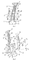
- FIG. 1 a vehicle pillar of a motor vehicle body is shown in the form of a B-pillar.
- the B-pillar has an elongated, hollow basic structure which extends in the installed state of the B-pillar on the body of the motor vehicle from bottom to top and can be divided into a foot area 1, a central area 2 and a head area 3.
- the B-pillar can be connected, starting from the bottom up, in the installed state with its foot area 1 on a body substructure, not shown.
- the B-pillar may have a lower flange portion 4, which may be T-shaped, for example, and may be fixed against a sill structure of the vehicle body, not shown.
- the B-pillar functional parts 5 such as a receptacle or a connection point for a closing wedge for the front door, a door lock, a door hinge or a rear door lock, can be kept in the installed state of the B-pillar on the vehicle body.
- the B-pillar can be connected in the installed state to a roof area of the body, not shown.
- the B-pillar may have an upper flange section 6, which may for example be T-shaped and serves to connect the B-pillar to the roof area of the motor vehicle body.
- the B-pillar has an inner shell 7, which faces a vehicle interior in the installed state on the body, a multi-part outer shell 8 facing away from the vehicle interior, which comprises a lower mold part 9 and an upper mold part 10, and a reinforcing element 11.
- the inner shell 7 may be a cold-formed component made of sheet steel, which has a constant wall thickness in the longitudinal and transverse directions. Basically, the inner shell 7, depending on the requirements of the B-pillar also have different wall thicknesses in the longitudinal and / or transverse direction.
- a steel material for example, a cold-rolled, microalloyed steel sheet, for example HC 420 LA +, can be provided, which can be provided with a double-sided zinc coating before the cold forming. From this coated strip material, a board can be worked out in a conventional manner, which is then cold-formed into the inner shell 7.
- cold forming the forming of metals at a temperature is understood to be well below the recrystallization temperature of the steel sheet used here, for example at room temperature.
- the multi-part outer shell 8 is functional through the lower mold part 9 and the upper Molded part 10 is formed, which are arranged overlapping each other only along an overlap region 12 and connected to each other.
- the lower mold part 9 and the upper mold part 10 are arranged offset to one another, wherein the two mold parts 9, 10 overlap in the overlap region 12, respectively, are arranged one above the other.
- the lower mold part 9 projects beyond the upper mold part 10 beyond the overlap region 12, ie in a first longitudinal direction X u of the B pillar.
- the upper mold part 10 projects beyond the overlapping region 12 in an opposite direction to the first longitudinal extension direction X u upward direction, that is, in a second longitudinal direction X o of the B-pillar.
- Both the first and the second longitudinal direction X u , X o are to be understood as vectors which point in opposite directions and are aligned parallel to one another. In the following, simplified reference will be made to the longitudinal direction X, if the direction indication is not to be emphasized upwards or downwards.
- the foot region 1 is thus determined solely by the lower molded part 9 and the head region 3 solely by the upper molded part 10.
- the overlap region 12 is a material duplication, wherein the lower mold part 9 made of sheet material and the upper mold part 10 made of fiber-reinforced plastic.
- the outer shell is a hybrid component, which is reinforced in the overlap region 12.
- the lower mold part 9 can be a hot-formed and hardened molded part.
- a strip material in this case for example a 22MnB5 steel sheet, may first be provided with an aluminum-silicon coating and flexibly rolled.
- the flexibly rolled steel sheet is also called Tailor Rolled Blank.
- a board is worked out, so that the board has a variable wall thickness over the longitudinal extent and in particular a constant wall thickness over the transverse extent.
- through holes 13 for the functional parts such as a receptacle or a connection point for a closing wedge for the front door, a door lock, a door hinge or a rear door lock, and further necessary openings introduced into the board.
- the through-openings 13 can also be introduced into the hot-formed and hardened lower molded part 9 by means of a laser-beam cutting method. Subsequently, the board is hot-worked, wherein hot-forming means forming metals above the recrystallization temperature of the 22MnB5 steel used here. If necessary, 9 soft local areas can be provided in the hardened lower mold part. Such soft zones may be provided, for example, in the main failure area of the B-pillar, ie in the area of the absorption and the degradation of crash energy. The soft zones are adjusted in terms of their material properties to the appropriate requirements, for example, a particularly high elongation at break.
- the upper molded part 10 is made of a fiber composite material with higher-strength fiber materials, for example made of carbon fiber reinforced plastic (CFRP) or glass fiber reinforced plastic (GRP).
- CFRP carbon fiber reinforced plastic
- GRP glass fiber reinforced plastic
- the individual fibers of the fiber composite may be laid as a scrim in which the fibers are ideally parallel and stretched, or as a multiaxial scrim in which the fibers are oriented not exclusively in a laminate plane but additional fibers perpendicular to the laminate plane or as sticks for targeted local reinforcement individual areas of the upper mold part 10 may be arranged.
- the upper molding 10 may have different wall thicknesses in the longitudinal and / or transverse direction of the upper molding 10.
- the inner shell 7 has an at least approximately flat and elongated basic shape, in which a plurality of recesses 14 have been introduced, which serve for example for carrying electrical cables or other vehicle components.
- the upper flange section 6 is designed to connect the B-pillar to the roof area.
- the support regions 16 On the edge side, essentially in the longitudinal direction X of the B-pillar, there are two lateral support areas 16, which are designed in the manner of a flange. Starting from the upper flange section 6, the support regions 16 extend over the middle region 2 of the B pillar into a lower end region 17 of the inner shell 7 and follow at least approximately the slightly curved course of the B pillar.
- the cross-direction of the B-pillar serve inner portions of the support portions 16 for connecting the inner shell 7 with the outer shell 8.
- the flange-like support areas 16 of the B-pillar have grooves 20 in the head area 3 of the B-pillar, which extend at least substantially in the longitudinal direction X of the B-pillar and / or at least approximately follow the slightly curved course of the B-pillar.
- the grooves 20 are used to connect the inner shell 7 with the upper mold part 10 of the outer shell. 8
- the inner shell 7 and the lower molded part 9 of the outer shell 8 are connected to one another at least in a materially bonded manner.
- the lower mold part 9 of the outer shell 8 has an approximately T-shaped basic shape.
- the lower flange portion 4 is formed for connection of the B-pillar to the body substructure.
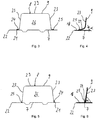
- FIG. 3 is a cross section of the B-pillar along the in FIG. 1 shown section line III-III shown.
- the lower molded part 9 has a U-shaped or hat profile-shaped cross-section above the lower flange section 4.
- connecting edges 21 of the lower mold part 9 offset from outer edges 22 of the inner shell 7, so that the inner shell 7 forms 16 single-layer flange portions of the B-pillar in the outer flange portions 18 of the support portions.
- the hat profile-shaped lower mold part 9 is supported on its inner walls 7 on its side walls 23 with two bent welding sections 24, which can be produced by trimming the draw-in flanges produced during the hot forming of the lower mold section 9.
- the lower molded part 9 is in contact with the inner shell 7 only along the two connecting edges 21 extending essentially in the longitudinal direction X.
- the connecting edges 21 are set back relative to the outer edges 22 of the inner shell 7, whereby the flange portions 18 of the flange-like support areas 16 of the inner shell 7 are exposed, respectively are not covered by the outer shell 8.
- the B-pillar is formed integrally along the outer flange portions 18 of the support portions 16 in the foot area 1 and in the central region 2 of the B-pillar, as shown in particular in FIGS FIGS. 3 to 7 is shown.
- the inner shell 7 In order to attach the B-pillar to the other vehicle components, for example the outer skin 19, to the roof or to glass surfaces, only the inner shell 7 must thus be joined or otherwise fastened along the single-layer flange sections 18 with the outer skin 19 or the further vehicle components. This can be done for example by welding or gluing.
- the inner shell 7 and the lower mold part 9 are connected along the two connecting edges 21 of the lower mold part 9 by means of a laser beam welding process, each with a continuous high energy welding seam 25, in short the weld.
- the weld 25 may extend over the entire edge length of the respective connecting edge 21. Due to the oblique arrangement of the two welding sections 24 on the inner shell 7, an angle of incidence a of, for example, approximately 15 ° is enclosed between the lower molded part 9 and the inner shell 7, so that an interior 26 opening into the interior of the B pillar is formed.
- the interior space 26 serves for degassing of metal vapors produced during the welding process. The metal vapors can escape at this time, in which the upper mold part 10 is not yet set, at the upper and lower end portion of the lower mold part 9.
- the inner shell 7 and the lower mold part 9 overlap only slightly by the narrow welding sections 24, so that the different wall thicknesses of the lower mold part 9 do not have to coincide with the sheet thickness of the inner shell 7.
- the inner shell 7 may be a standardized strike plate, which has uniformly across the market a sheet thickness.
- only the lower mold part 9 is to be adapted to application or market-specific specifications with regard to the crash protection, by selectively reinforcing or softening certain portions of the lower mold part 9 by increasing or decreasing the sheet thickness.
- FIG. 6 an alternative cross-section of the B-pillar is shown.
- the lower mold part 9 receives in cross-section a U-shaped basic shape, wherein the two welding portions 24 are formed on the outer edge regions of the side walls 23.
- the width of the weld portions 24 are limited to the width of the welds 25, so that the width of the weld portions 24 may be less than 2 millimeters.
- the lower mold part 9 is thus arranged opposite the inner shell 7 in the joint with an angle of attack a of approximately 80 ° and is joined along the two connecting edges 21 to the inner shell 7 by means of the laser beam welding process.
- the interior 26 which opens into the interior of the B-pillar in turn serves for degassing metal vapors produced during the welding process.
- the upper mold part 10 is externally placed on the lower mold part 9, which is at least materially connected to the inner shell 7 as described above, positively fitted and materially and non-positively connected to the lower mold part 9.
- the upper mold part 10 has an elongated basic shape with a U-shaped cross section. Concretely, the upper mold part 10 has an outer wall 27 and two side walls 28, which, as in FIG. 7 shown are spaced from the inner shell 7. The upper mold part 10 lies in the overlapping area 12 flat on the outside of the lower mold part 9. Between the upper mold part 10 and the lower mold part 9, a barrier layer, not shown here, can be arranged to avoid contact corrosion.
- the longitudinal extent of the overlap region 12 is about 50% to 60% of the longitudinal extension of the lower mold part 9 and about 35% to 45% of the longitudinal extent of the upper mold part 10. Since a vehicle body for the protection of the occupants is usually designed to be stiff, especially in the middle region 2 of the B-pillar, the overlapping region 12 can expediently be formed in the middle region 2 of the B pillar. In principle, possible and conceivable is also that, depending on the requirements of the vehicle body of the overlap region 12 in the foot or head area 1, 3 of the B-pillar is formed and / or extends over several areas 1, 2, 3 of the B-pillar.
- the lower mold part 9 and the upper mold part 10 are also materially and non-positively connected to each other.
- the two mold parts 9, 10 are glued together in the overlapping region 12.
- the fastening means are for attaching the functional parts 5, such as a receptacle or a connection point for a closing wedge for the front door, a door lock, a door hinge or a rear door lock formed.
- the upper mold part 10 and the lower mold part 9 for receiving the fastening means, the upper mold part 10 and the lower mold part 9 in their outer walls 27, 29 arranged one above the other and covering through openings 30, 13. Furthermore, sleeves 31 are inserted in the passage openings 30 of the upper molding 10 in order to avoid contact corrosion between the fastening means and the upper molding 10.
- the sleeves 31 may be painted or made of titanium or other corrosion resistant material.
- the reinforcing element 11 in the overlapping region 12 on the outer surface facing away from the inner shell 7 outer surface of the upper mold part 10, the reinforcing element 11 may be arranged from sheet metal material for supporting the fastening means.
- the reinforcing element 11 may be in the form of a piece of sheet metal, which may also be referred to as a patch.
- the reinforcing element 11 may be made of a metal sheet, in particular a steel sheet.
- a barrier layer between the reinforcing element 11 and the upper mold part 10 may also be provided a barrier layer, not shown, to avoid contact corrosion.
- the lower mold part 9 and the upper mold part 10 in the overlapping region 12 in the side walls 23, 28 have through holes 32, 33 for receiving further fastening means by the two mold parts 9, 10 can also be positively connected to each other.
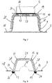
- FIG. 8 is a cross section of the B-pillar along the in FIG. 1 shown section line XIII-XIII, which lies in the head area 3 of the B-pillar.
- the upper mold part 10 can at the upper flange portion 6, for example by rivet connections not shown in detail, and at the central region 2, for example by riveting, with which the functional parts 5 are fixed to the B-pillar, and by means of the connection with the lower mold part 9 at be fixed to the inner shell 7.
- the upper mold part 10 may be materially connected to the inner shell 7.
- connecting portions 34 are formed, which engage positively in the grooves 20 of the inner shell 7.
- the connecting portions 34 are glued in the grooves 20 by means of adhesive beads 15 with the inner shell 7. In this way, the upper mold part 10 is fixed to the inner shell 7 in the head region 3 of the B pillar.
- the connecting portions 34 'of the upper mold part 10 can also be formed in the form of bent edge regions of the upper mold part 10. Due to the folded, respectively bent edge regions, which form the connecting portions 34 'of the upper mold part 10, the loaded with tensile stresses edge region of the upper mold part 10 is reinforced and reduces the notch sensitivity.
- each angle ⁇ is enclosed by about 110 °.
- the B-pillar in the head region 3 is thus spring-like and has a deformable basic shape in the elastic region.
- the spring property of the upper mold part 10 is improved at an entry of a crash energy, that is, the upper mold part 10 can absorb more energy is in FIG. 8 recognizable that the inner shell 7 has a material-weakened portion 38 which is disposed between the side walls 28 of the upper mold part 10.
- the material-weakened portion 38 extends above the overlap region 12 in the second longitudinal direction of the B-pillar.
- the side walls 28 of the upper mold part 10 can move back out after relieving, that is, the distance between the free longitudinal ends of the side walls 28 increases again. In this way, the upper mold part 10 can breathe without breaking.
- the inner shell 7 is then pulled apart again along the material-weakened section 38 by the free longitudinal ends which move outwards, which engage in the grooves 20 of the inner shell 7, and the upper molded part 10 releases the absorbed energy again.
- FIG. 10 is another possible embodiment of the B-pillar based on a cross-section through the B-pillar along in FIG. 1 shown section line XIII-XIII shown.
- the upper mold part 10 in transition regions 35 between the outer wall 27 and the side walls 28 each have a hinged material weakening in the form of a notch 36, to illustrate the differences only in the with Look at FIG. 10 left transition region 35 is shown.
- the spring behavior of the B-pillar can be trimmed in an externally acting on the B-pillar force.
- the material weakening here in the form of the notch 36, can, as in FIG. 10 shown with both the straight formed connecting portions 34 according to FIG. 8 as well as with the in FIG. 9 shown bent connecting portions 34 'are combined.
- a materialgeschwumbleter section 38 may be provided which is disposed between the side walls 28 of the upper mold part 10 and extends above the overlap region 12 in the second longitudinal direction of the B-pillar.
- the lower mold part 9 is preferably first connected to the inner shell 7.
- the lower mold part 9 is welded to the inner shell 7, in particular by means of a high-energy beam welding process, which enters the thermal energy lower and more concentrated in the components to be joined in comparison to other welding processes.
- a high-energy beam welding process which enters the thermal energy lower and more concentrated in the components to be joined in comparison to other welding processes.
- the connecting edge 21 is also easily accessible on the side, whereby the use of high energy beam welding process is simplified.
- the laser beam welding method is particularly suitable as a high energy beam welding method, wherein the selected welding method can be carried out with or without additional material.
- the high energy beam weld 25 is generated over at least 50% of the edge length of the joint edge 21. In this case, a continuous or interrupted web can be welded.
- the upper mold part 10 is placed on the lower mold part 9 and the inner shell 7 such that on the one hand, the lower mold part 9 and the upper mold part 10 overlap only along an overlap region 12 and other, the upper mold part 10 is supported in the head area 3 on the inner shell 7.
- the upper mold part 10 is further flat with the lower mold part 9 and with the inner shell 7 in the Grooved 20 glued.
- the B-pillar can be fastened to the vehicle body, wherein the lower flange portion 4 is connected to the body substructure and the upper flange portion 6 at the roof region of the body, in particular by means of a welding process.
- the upper molded part 10 can only now be placed on the lower molded part 9 and the inner shell 7 and connected to them.
- the upper mold part 9 and the lower mold part 10 are also frictionally connected to one another by the fastening means which engage through the through-openings 30, 23.
Applications Claiming Priority (1)
| Application Number | Priority Date | Filing Date | Title |
|---|---|---|---|
| DE102015115439.0A DE102015115439B3 (de) | 2015-09-14 | 2015-09-14 | B-Säule für eine Kraftfahrzeugkarosserie und Verfahren zum Herstellen einer B-Säule |
Publications (2)
| Publication Number | Publication Date |
|---|---|
| EP3150466A1 EP3150466A1 (de) | 2017-04-05 |
| EP3150466B1 true EP3150466B1 (de) | 2018-04-11 |
Family
ID=56926059
Family Applications (1)
| Application Number | Title | Priority Date | Filing Date |
|---|---|---|---|
| EP16188525.6A Active EP3150466B1 (de) | 2015-09-14 | 2016-09-13 | B-säule für eine kraftfahrzeugkarosserie und verfahren zum herstellen einer b-säule |
Country Status (6)
| Country | Link |
|---|---|
| US (1) | US10065683B2 (ko) |
| EP (1) | EP3150466B1 (ko) |
| JP (1) | JP6573856B2 (ko) |
| KR (1) | KR20170032192A (ko) |
| CN (1) | CN106515862B (ko) |
| DE (1) | DE102015115439B3 (ko) |
Families Citing this family (22)
| Publication number | Priority date | Publication date | Assignee | Title |
|---|---|---|---|---|
| DE102013007805A1 (de) * | 2013-05-07 | 2014-11-13 | Daimler Ag | Säule für eine Kraftfahrzeug-Rohbaustruktur, Verfahren zur Herstellung einer Säule und Kraftfahrzeug-Rohbaustruktur |
| US10633031B2 (en) * | 2015-12-18 | 2020-04-28 | Autotech Engineering S.L. | B-pillar central beam and method for manufacturing |
| DE102016201036A1 (de) * | 2016-01-26 | 2017-07-27 | Zf Friedrichshafen Ag | Verfahren zur Herstellung eines Bauteils und nach diesem Verfahren hergestelltes Bauteil |
| US10124833B2 (en) * | 2016-09-01 | 2018-11-13 | Ford Global Technologies, Llc | B-pillar assembly for vehicle body |
| DE102016118366A1 (de) * | 2016-09-28 | 2018-03-29 | Bayerische Motoren Werke Ag | Strukturbauteil für eine kraftfahrzeugkarosserie |
| KR101866080B1 (ko) * | 2016-10-31 | 2018-06-11 | 현대자동차주식회사 | 센터필라용 충격 흡수 레인프 구조 |
| JP6555303B2 (ja) * | 2017-07-28 | 2019-08-07 | マツダ株式会社 | 車両の側部車体構造 |
| JP6898169B2 (ja) * | 2017-08-02 | 2021-07-07 | トヨタ自動車株式会社 | ボディ骨格構造 |
| US11351590B2 (en) * | 2017-08-10 | 2022-06-07 | Honda Motor Co., Ltd. | Features of dissimilar material-reinforced blanks and extrusions for forming |
| DE102018207026A1 (de) * | 2017-10-06 | 2019-04-11 | Sms Group Gmbh | Multiflexible Walzanlage |
| GB2571615B (en) * | 2018-01-09 | 2022-07-27 | Faurecia Automotive Composites | Structural part for a body in white of a vehicle and associated manufacturing method |
| CN111565999B (zh) * | 2018-01-12 | 2023-08-11 | 日本制铁株式会社 | 前柱外板 |
| JP6767413B2 (ja) * | 2018-03-12 | 2020-10-14 | 株式会社豊田自動織機 | センターピラー構造 |
| JP2019209767A (ja) * | 2018-06-01 | 2019-12-12 | 本田技研工業株式会社 | 車両用構造体 |
| DE102018113141A1 (de) * | 2018-06-01 | 2019-12-05 | Muhr Und Bender Kg | B-Säule für eine Kraftfahrzeugkarosserie sowie Kraftfahrzeugkarosserie mit einer solchen B-Säule |
| CN108791504A (zh) * | 2018-06-13 | 2018-11-13 | 芜湖恒信汽车内饰制造有限公司 | 一种车身结构及具有该结构的车身b柱和车身c柱 |
| JP7236303B2 (ja) * | 2019-03-27 | 2023-03-09 | 日産自動車株式会社 | 車体のピラー構造 |
| US11117620B2 (en) | 2019-06-06 | 2021-09-14 | Ford Global Technologies, Llc | Vehicle body-in-white panel with reinforcing and energy absorbing structures |
| EP4023535A4 (en) * | 2019-09-11 | 2022-08-10 | Nippon Steel Corporation | INTERIOR PART OF A CENTER COLUMN AND CENTER COLUMN |
| KR20220075120A (ko) | 2020-11-27 | 2022-06-07 | 서진산업 주식회사 | 강성증대를 위한 엠보싱 무늬 적용 비필라 |
| US20240109400A1 (en) * | 2021-01-20 | 2024-04-04 | Tata Steel Limited | A reinforcement member for a vehicle |
| FR3129423A1 (fr) * | 2021-11-24 | 2023-05-26 | Psa Automobiles Sa | Plaquette d’indexation de charnière de porte renforçant un pilier pour véhicule automobile |
Family Cites Families (19)
| Publication number | Priority date | Publication date | Assignee | Title |
|---|---|---|---|---|
| JPH043854Y2 (ko) * | 1985-07-16 | 1992-02-05 | ||
| JP2591417Y2 (ja) * | 1992-02-05 | 1999-03-03 | トヨタ車体株式会社 | ドア取付用ピラー |
| DE102005038488A1 (de) | 2005-08-13 | 2007-02-22 | Bayerische Motoren Werke Ag | Verstärkungsblech für eine B-Säule einer Fahrzeugkarosserie |
| DE102006027546A1 (de) * | 2006-06-14 | 2007-12-20 | Volkswagen Ag | Aufprallschutzverstärkungsteil |
| SE530228C2 (sv) * | 2006-08-25 | 2008-04-01 | Gestamp Hardtech Ab | Sätt att varmforma och härda en plåtdetalj, samt en B-stolpe till ett fordon |
| DE102007053353B4 (de) * | 2007-10-30 | 2017-06-08 | Deutsches Zentrum für Luft- und Raumfahrt e.V. | Karosseriesäule für Fahrzeuge und Fahrzeugkarosserie |
| US8662567B2 (en) * | 2009-02-02 | 2014-03-04 | Vari-Form, Inc. | Vehicle roof support pillar assembly |
| DE202010002099U1 (de) * | 2010-02-09 | 2011-06-09 | Voestalpine Automotive Gmbh | Verbundbauteil für ein Fahrzeug |
| CN201646871U (zh) * | 2010-03-19 | 2010-11-24 | 浙江吉利汽车研究院有限公司 | 一种汽车的中柱 |
| FR2959981B1 (fr) * | 2010-05-11 | 2012-05-04 | Peugeot Citroen Automobiles Sa | Element de renfort de pied de milieu d'un vehicule. |
| DE102011111232A1 (de) * | 2011-08-20 | 2013-02-21 | GM Global Technology Operations LLC (n. d. Gesetzen des Staates Delaware) | Leichtbauteil, insbesondere Karosseriesäulenverstärkung und Verfahren zur Herstellung des Leichtbauteils |
| DE102012203888A1 (de) * | 2012-03-13 | 2013-09-19 | Bayerische Motoren Werke Aktiengesellschaft | Baugruppe einer Kraftfahrzeugkarosserie |
| CN202728352U (zh) * | 2012-08-14 | 2013-02-13 | 东风汽车公司 | 一种乘用车b柱结构 |
| JP6032629B2 (ja) * | 2013-08-22 | 2016-11-30 | 本田技研工業株式会社 | 自動車のセンターピラー構造 |
| DE102013017269A1 (de) * | 2013-10-17 | 2014-08-28 | Daimler Ag | Karosseriebauteil und Kraftfahrzeug mit dem Karosseriebauteil |
| CN203601385U (zh) * | 2013-11-01 | 2014-05-21 | 上汽通用五菱汽车股份有限公司 | 一种b柱上端接头结构 |
| KR101592645B1 (ko) * | 2013-12-19 | 2016-02-05 | 기아자동차주식회사 | 자동차용 센터 필러 아우터 및 이의 제조방법 |
| DE102014003378A1 (de) * | 2014-03-05 | 2015-09-10 | Daimler Ag | Fahrzeugsäule für eine Karosserie eines Personenkraftwagens |
| CN204527331U (zh) * | 2015-01-08 | 2015-08-05 | 郑州比克新能源汽车有限公司 | 一种电动车身b柱结构 |
-
2015
- 2015-09-14 DE DE102015115439.0A patent/DE102015115439B3/de not_active Expired - Fee Related
-
2016
- 2016-09-09 US US15/260,338 patent/US10065683B2/en active Active
- 2016-09-12 KR KR1020160116993A patent/KR20170032192A/ko unknown
- 2016-09-13 EP EP16188525.6A patent/EP3150466B1/de active Active
- 2016-09-14 CN CN201610824515.2A patent/CN106515862B/zh active Active
- 2016-09-14 JP JP2016179371A patent/JP6573856B2/ja active Active
Non-Patent Citations (1)
| Title |
|---|
| None * |
Also Published As
| Publication number | Publication date |
|---|---|
| US10065683B2 (en) | 2018-09-04 |
| CN106515862A (zh) | 2017-03-22 |
| KR20170032192A (ko) | 2017-03-22 |
| US20170073017A1 (en) | 2017-03-16 |
| CN106515862B (zh) | 2019-05-28 |
| JP2017061304A (ja) | 2017-03-30 |
| JP6573856B2 (ja) | 2019-09-11 |
| DE102015115439B3 (de) | 2017-01-05 |
| EP3150466A1 (de) | 2017-04-05 |
Similar Documents
| Publication | Publication Date | Title |
|---|---|---|
| EP3150466B1 (de) | B-säule für eine kraftfahrzeugkarosserie und verfahren zum herstellen einer b-säule | |
| EP3293095B1 (de) | B-säule für eine kraftfahrzeugkarosserie sowie kraftfahrzeugkarosserie mit einer solchen b-säule | |
| EP2985209B1 (de) | Strukturbauteil und verfahren zur herstellung eines strukturbauteils | |
| EP1912849B1 (de) | Verstärkungsblech für eine b-säule einer fahrzeugkarossehe | |
| DE112016000650B4 (de) | Karosseriestruktur eines fahrzeugs | |
| EP2195226B1 (de) | Verfahren zur herstellung eines weitestgehend flächenförmigen bauteileverbundes und weitestgehend flächenförmiger bauteileverbund dazu | |
| DE102013015420B4 (de) | Stoßfängersystem und Verfahren für die Herstellung eines Stoßfängersystems | |
| EP3045551A1 (de) | Kraftfahrzeugkomponente und karosseriebauteil | |
| WO2012007346A1 (de) | B-säulenverstärkung eines kraftfahrzeugs | |
| EP3519278B1 (de) | Strukturbauteil für eine kraftfahrzeugkarosserie | |
| DE102013015421B4 (de) | Stoßfängersystem | |
| EP2014539A1 (de) | Kraftfahrzeugkarosserie mit seitlichen Schwellern | |
| EP0953495A2 (de) | Karosseriesäule bzw. Verfahren zur Herstellung einer Karosseriesäule für eine Fahrzeugkarosserie | |
| WO2005021177A1 (de) | Verfahren zum umformen von blechen | |
| EP2332810B1 (de) | Karosserie eines Kraftfahrzeugs | |
| DE102015012262B4 (de) | Tür für einen Kraftwagen | |
| DE102015204917A1 (de) | Seitentür für ein Fahrzeug sowie Fahrzeug mit einer derartigen Seitentür | |
| DE102015000979B3 (de) | Rahmenelement, insbesondere Seitenwandrahmenelement, für eine Fahrzeugkarosserie sowie Verfahren zur Herstellung eines Rahmenelementes für eine Fahrzeugkarosserie | |
| EP3575189B1 (de) | B-säule für eine kraftfahrzeugkarosserie sowie kraftfahrzeugkarosserie mit einer solchen b-säule | |
| DE102011052291A1 (de) | Kraftfahrzeugbauteil sowie Verfahren zur Herstellung eines Kraftfahrzeugbauteils | |
| DE102006019479B4 (de) | Türaufbau mit Tailored Blanks | |
| DE102016222116A1 (de) | Karosserie-Dachstruktur für ein zweispuriges Fahrzeug | |
| WO2013041177A1 (de) | Dachrahmenteil einer karosserie eines personenkraftwagens | |
| DE102007050227B4 (de) | Fahrzeugtür | |
| WO2004026666A1 (de) | Rohbaustruktur einer fahrzeugkarosserie |
Legal Events
| Date | Code | Title | Description |
|---|---|---|---|
| PUAI | Public reference made under article 153(3) epc to a published international application that has entered the european phase |
Free format text: ORIGINAL CODE: 0009012 |
|
| STAA | Information on the status of an ep patent application or granted ep patent |
Free format text: STATUS: THE APPLICATION HAS BEEN PUBLISHED |
|
| AK | Designated contracting states |
Kind code of ref document: A1 Designated state(s): AL AT BE BG CH CY CZ DE DK EE ES FI FR GB GR HR HU IE IS IT LI LT LU LV MC MK MT NL NO PL PT RO RS SE SI SK SM TR |
|
| AX | Request for extension of the european patent |
Extension state: BA ME |
|
| STAA | Information on the status of an ep patent application or granted ep patent |
Free format text: STATUS: REQUEST FOR EXAMINATION WAS MADE |
|
| 17P | Request for examination filed |
Effective date: 20170609 |
|
| RBV | Designated contracting states (corrected) |
Designated state(s): AL AT BE BG CH CY CZ DE DK EE ES FI FR GB GR HR HU IE IS IT LI LT LU LV MC MK MT NL NO PL PT RO RS SE SI SK SM TR |
|
| GRAP | Despatch of communication of intention to grant a patent |
Free format text: ORIGINAL CODE: EPIDOSNIGR1 |
|
| STAA | Information on the status of an ep patent application or granted ep patent |
Free format text: STATUS: GRANT OF PATENT IS INTENDED |
|
| INTG | Intention to grant announced |
Effective date: 20171102 |
|
| GRAS | Grant fee paid |
Free format text: ORIGINAL CODE: EPIDOSNIGR3 |
|
| GRAA | (expected) grant |
Free format text: ORIGINAL CODE: 0009210 |
|
| STAA | Information on the status of an ep patent application or granted ep patent |
Free format text: STATUS: THE PATENT HAS BEEN GRANTED |
|
| AK | Designated contracting states |
Kind code of ref document: B1 Designated state(s): AL AT BE BG CH CY CZ DE DK EE ES FI FR GB GR HR HU IE IS IT LI LT LU LV MC MK MT NL NO PL PT RO RS SE SI SK SM TR |
|
| REG | Reference to a national code |
Ref country code: GB Ref legal event code: FG4D Free format text: NOT ENGLISH |
|
| REG | Reference to a national code |
Ref country code: CH Ref legal event code: EP |
|
| REG | Reference to a national code |
Ref country code: AT Ref legal event code: REF Ref document number: 987717 Country of ref document: AT Kind code of ref document: T Effective date: 20180415 |
|
| REG | Reference to a national code |
Ref country code: IE Ref legal event code: FG4D Free format text: LANGUAGE OF EP DOCUMENT: GERMAN |
|
| REG | Reference to a national code |
Ref country code: DE Ref legal event code: R096 Ref document number: 502016000828 Country of ref document: DE |
|
| REG | Reference to a national code |
Ref country code: SE Ref legal event code: TRGR |
|
| REG | Reference to a national code |
Ref country code: NL Ref legal event code: MP Effective date: 20180411 |
|
| REG | Reference to a national code |
Ref country code: LT Ref legal event code: MG4D |
|
| REG | Reference to a national code |
Ref country code: FR Ref legal event code: PLFP Year of fee payment: 3 |
|
| PG25 | Lapsed in a contracting state [announced via postgrant information from national office to epo] |
Ref country code: NL Free format text: LAPSE BECAUSE OF FAILURE TO SUBMIT A TRANSLATION OF THE DESCRIPTION OR TO PAY THE FEE WITHIN THE PRESCRIBED TIME-LIMIT Effective date: 20180411 |
|
| PG25 | Lapsed in a contracting state [announced via postgrant information from national office to epo] |
Ref country code: BG Free format text: LAPSE BECAUSE OF FAILURE TO SUBMIT A TRANSLATION OF THE DESCRIPTION OR TO PAY THE FEE WITHIN THE PRESCRIBED TIME-LIMIT Effective date: 20180711 Ref country code: ES Free format text: LAPSE BECAUSE OF FAILURE TO SUBMIT A TRANSLATION OF THE DESCRIPTION OR TO PAY THE FEE WITHIN THE PRESCRIBED TIME-LIMIT Effective date: 20180411 Ref country code: PL Free format text: LAPSE BECAUSE OF FAILURE TO SUBMIT A TRANSLATION OF THE DESCRIPTION OR TO PAY THE FEE WITHIN THE PRESCRIBED TIME-LIMIT Effective date: 20180411 Ref country code: LT Free format text: LAPSE BECAUSE OF FAILURE TO SUBMIT A TRANSLATION OF THE DESCRIPTION OR TO PAY THE FEE WITHIN THE PRESCRIBED TIME-LIMIT Effective date: 20180411 Ref country code: AL Free format text: LAPSE BECAUSE OF FAILURE TO SUBMIT A TRANSLATION OF THE DESCRIPTION OR TO PAY THE FEE WITHIN THE PRESCRIBED TIME-LIMIT Effective date: 20180411 Ref country code: FI Free format text: LAPSE BECAUSE OF FAILURE TO SUBMIT A TRANSLATION OF THE DESCRIPTION OR TO PAY THE FEE WITHIN THE PRESCRIBED TIME-LIMIT Effective date: 20180411 Ref country code: NO Free format text: LAPSE BECAUSE OF FAILURE TO SUBMIT A TRANSLATION OF THE DESCRIPTION OR TO PAY THE FEE WITHIN THE PRESCRIBED TIME-LIMIT Effective date: 20180711 |
|
| PG25 | Lapsed in a contracting state [announced via postgrant information from national office to epo] |
Ref country code: HR Free format text: LAPSE BECAUSE OF FAILURE TO SUBMIT A TRANSLATION OF THE DESCRIPTION OR TO PAY THE FEE WITHIN THE PRESCRIBED TIME-LIMIT Effective date: 20180411 Ref country code: RS Free format text: LAPSE BECAUSE OF FAILURE TO SUBMIT A TRANSLATION OF THE DESCRIPTION OR TO PAY THE FEE WITHIN THE PRESCRIBED TIME-LIMIT Effective date: 20180411 Ref country code: GR Free format text: LAPSE BECAUSE OF FAILURE TO SUBMIT A TRANSLATION OF THE DESCRIPTION OR TO PAY THE FEE WITHIN THE PRESCRIBED TIME-LIMIT Effective date: 20180712 Ref country code: LV Free format text: LAPSE BECAUSE OF FAILURE TO SUBMIT A TRANSLATION OF THE DESCRIPTION OR TO PAY THE FEE WITHIN THE PRESCRIBED TIME-LIMIT Effective date: 20180411 |
|
| PG25 | Lapsed in a contracting state [announced via postgrant information from national office to epo] |
Ref country code: PT Free format text: LAPSE BECAUSE OF FAILURE TO SUBMIT A TRANSLATION OF THE DESCRIPTION OR TO PAY THE FEE WITHIN THE PRESCRIBED TIME-LIMIT Effective date: 20180813 |
|
| REG | Reference to a national code |
Ref country code: DE Ref legal event code: R097 Ref document number: 502016000828 Country of ref document: DE |
|
| PG25 | Lapsed in a contracting state [announced via postgrant information from national office to epo] |
Ref country code: SK Free format text: LAPSE BECAUSE OF FAILURE TO SUBMIT A TRANSLATION OF THE DESCRIPTION OR TO PAY THE FEE WITHIN THE PRESCRIBED TIME-LIMIT Effective date: 20180411 Ref country code: RO Free format text: LAPSE BECAUSE OF FAILURE TO SUBMIT A TRANSLATION OF THE DESCRIPTION OR TO PAY THE FEE WITHIN THE PRESCRIBED TIME-LIMIT Effective date: 20180411 Ref country code: CZ Free format text: LAPSE BECAUSE OF FAILURE TO SUBMIT A TRANSLATION OF THE DESCRIPTION OR TO PAY THE FEE WITHIN THE PRESCRIBED TIME-LIMIT Effective date: 20180411 Ref country code: DK Free format text: LAPSE BECAUSE OF FAILURE TO SUBMIT A TRANSLATION OF THE DESCRIPTION OR TO PAY THE FEE WITHIN THE PRESCRIBED TIME-LIMIT Effective date: 20180411 Ref country code: EE Free format text: LAPSE BECAUSE OF FAILURE TO SUBMIT A TRANSLATION OF THE DESCRIPTION OR TO PAY THE FEE WITHIN THE PRESCRIBED TIME-LIMIT Effective date: 20180411 |
|
| PLBE | No opposition filed within time limit |
Free format text: ORIGINAL CODE: 0009261 |
|
| STAA | Information on the status of an ep patent application or granted ep patent |
Free format text: STATUS: NO OPPOSITION FILED WITHIN TIME LIMIT |
|
| PG25 | Lapsed in a contracting state [announced via postgrant information from national office to epo] |
Ref country code: SM Free format text: LAPSE BECAUSE OF FAILURE TO SUBMIT A TRANSLATION OF THE DESCRIPTION OR TO PAY THE FEE WITHIN THE PRESCRIBED TIME-LIMIT Effective date: 20180411 |
|
| 26N | No opposition filed |
Effective date: 20190114 |
|
| PG25 | Lapsed in a contracting state [announced via postgrant information from national office to epo] |
Ref country code: MC Free format text: LAPSE BECAUSE OF FAILURE TO SUBMIT A TRANSLATION OF THE DESCRIPTION OR TO PAY THE FEE WITHIN THE PRESCRIBED TIME-LIMIT Effective date: 20180411 |
|
| PG25 | Lapsed in a contracting state [announced via postgrant information from national office to epo] |
Ref country code: SI Free format text: LAPSE BECAUSE OF FAILURE TO SUBMIT A TRANSLATION OF THE DESCRIPTION OR TO PAY THE FEE WITHIN THE PRESCRIBED TIME-LIMIT Effective date: 20180411 |
|
| REG | Reference to a national code |
Ref country code: BE Ref legal event code: MM Effective date: 20180930 |
|
| REG | Reference to a national code |
Ref country code: IE Ref legal event code: MM4A |
|
| PG25 | Lapsed in a contracting state [announced via postgrant information from national office to epo] |
Ref country code: LU Free format text: LAPSE BECAUSE OF NON-PAYMENT OF DUE FEES Effective date: 20180913 |
|
| PG25 | Lapsed in a contracting state [announced via postgrant information from national office to epo] |
Ref country code: IE Free format text: LAPSE BECAUSE OF NON-PAYMENT OF DUE FEES Effective date: 20180913 |
|
| PG25 | Lapsed in a contracting state [announced via postgrant information from national office to epo] |
Ref country code: BE Free format text: LAPSE BECAUSE OF NON-PAYMENT OF DUE FEES Effective date: 20180930 |
|
| PGFP | Annual fee paid to national office [announced via postgrant information from national office to epo] |
Ref country code: IT Payment date: 20190930 Year of fee payment: 4 Ref country code: SE Payment date: 20190917 Year of fee payment: 4 Ref country code: FR Payment date: 20190927 Year of fee payment: 4 |
|
| PG25 | Lapsed in a contracting state [announced via postgrant information from national office to epo] |
Ref country code: MT Free format text: LAPSE BECAUSE OF FAILURE TO SUBMIT A TRANSLATION OF THE DESCRIPTION OR TO PAY THE FEE WITHIN THE PRESCRIBED TIME-LIMIT Effective date: 20180411 |
|
| PG25 | Lapsed in a contracting state [announced via postgrant information from national office to epo] |
Ref country code: TR Free format text: LAPSE BECAUSE OF FAILURE TO SUBMIT A TRANSLATION OF THE DESCRIPTION OR TO PAY THE FEE WITHIN THE PRESCRIBED TIME-LIMIT Effective date: 20180411 |
|
| REG | Reference to a national code |
Ref country code: CH Ref legal event code: PL |
|
| PG25 | Lapsed in a contracting state [announced via postgrant information from national office to epo] |
Ref country code: MK Free format text: LAPSE BECAUSE OF NON-PAYMENT OF DUE FEES Effective date: 20180411 Ref country code: HU Free format text: LAPSE BECAUSE OF FAILURE TO SUBMIT A TRANSLATION OF THE DESCRIPTION OR TO PAY THE FEE WITHIN THE PRESCRIBED TIME-LIMIT; INVALID AB INITIO Effective date: 20160913 Ref country code: CY Free format text: LAPSE BECAUSE OF FAILURE TO SUBMIT A TRANSLATION OF THE DESCRIPTION OR TO PAY THE FEE WITHIN THE PRESCRIBED TIME-LIMIT Effective date: 20180411 |
|
| PG25 | Lapsed in a contracting state [announced via postgrant information from national office to epo] |
Ref country code: LI Free format text: LAPSE BECAUSE OF NON-PAYMENT OF DUE FEES Effective date: 20190930 Ref country code: CH Free format text: LAPSE BECAUSE OF NON-PAYMENT OF DUE FEES Effective date: 20190930 Ref country code: IS Free format text: LAPSE BECAUSE OF FAILURE TO SUBMIT A TRANSLATION OF THE DESCRIPTION OR TO PAY THE FEE WITHIN THE PRESCRIBED TIME-LIMIT Effective date: 20180811 |
|
| GBPC | Gb: european patent ceased through non-payment of renewal fee |
Effective date: 20200913 |
|
| PG25 | Lapsed in a contracting state [announced via postgrant information from national office to epo] |
Ref country code: FR Free format text: LAPSE BECAUSE OF NON-PAYMENT OF DUE FEES Effective date: 20200930 |
|
| PG25 | Lapsed in a contracting state [announced via postgrant information from national office to epo] |
Ref country code: SE Free format text: LAPSE BECAUSE OF NON-PAYMENT OF DUE FEES Effective date: 20200914 Ref country code: GB Free format text: LAPSE BECAUSE OF NON-PAYMENT OF DUE FEES Effective date: 20200913 |
|
| REG | Reference to a national code |
Ref country code: SE Ref legal event code: EUG |
|
| PG25 | Lapsed in a contracting state [announced via postgrant information from national office to epo] |
Ref country code: IT Free format text: LAPSE BECAUSE OF NON-PAYMENT OF DUE FEES Effective date: 20200913 |
|
| REG | Reference to a national code |
Ref country code: AT Ref legal event code: MM01 Ref document number: 987717 Country of ref document: AT Kind code of ref document: T Effective date: 20210913 |
|
| PG25 | Lapsed in a contracting state [announced via postgrant information from national office to epo] |
Ref country code: AT Free format text: LAPSE BECAUSE OF NON-PAYMENT OF DUE FEES Effective date: 20210913 |
|
| PGFP | Annual fee paid to national office [announced via postgrant information from national office to epo] |
Ref country code: DE Payment date: 20230908 Year of fee payment: 8 |