EP3147191A1 - Resonatorstruktur für ein sattelfahrzeug - Google Patents
Resonatorstruktur für ein sattelfahrzeug Download PDFInfo
- Publication number
- EP3147191A1 EP3147191A1 EP16183770.3A EP16183770A EP3147191A1 EP 3147191 A1 EP3147191 A1 EP 3147191A1 EP 16183770 A EP16183770 A EP 16183770A EP 3147191 A1 EP3147191 A1 EP 3147191A1
- Authority
- EP
- European Patent Office
- Prior art keywords
- resonator
- head box
- vehicle
- head
- box
- Prior art date
- Legal status (The legal status is an assumption and is not a legal conclusion. Google has not performed a legal analysis and makes no representation as to the accuracy of the status listed.)
- Granted
Links
- 238000005192 partition Methods 0.000 claims description 22
- 238000004891 communication Methods 0.000 claims description 16
- 230000001743 silencing effect Effects 0.000 abstract description 14
- 230000002708 enhancing effect Effects 0.000 abstract description 5
- 238000005549 size reduction Methods 0.000 abstract description 3
- 230000001965 increasing effect Effects 0.000 description 7
- 238000005242 forging Methods 0.000 description 5
- 239000000463 material Substances 0.000 description 5
- 239000002828 fuel tank Substances 0.000 description 3
- 238000005304 joining Methods 0.000 description 3
- 229910052751 metal Inorganic materials 0.000 description 3
- 239000002184 metal Substances 0.000 description 3
- 238000000034 method Methods 0.000 description 3
- 238000003466 welding Methods 0.000 description 3
- 238000000071 blow moulding Methods 0.000 description 2
- 239000000470 constituent Substances 0.000 description 2
- 238000010586 diagram Methods 0.000 description 2
- 230000037361 pathway Effects 0.000 description 2
- 239000011347 resin Substances 0.000 description 2
- 229920005989 resin Polymers 0.000 description 2
- 229910000831 Steel Inorganic materials 0.000 description 1
- 229910052782 aluminium Inorganic materials 0.000 description 1
- XAGFODPZIPBFFR-UHFFFAOYSA-N aluminium Chemical compound [Al] XAGFODPZIPBFFR-UHFFFAOYSA-N 0.000 description 1
- 150000002739 metals Chemical class 0.000 description 1
- 238000012986 modification Methods 0.000 description 1
- 230000004048 modification Effects 0.000 description 1
- 239000010959 steel Substances 0.000 description 1
- 239000000725 suspension Substances 0.000 description 1
- 238000011144 upstream manufacturing Methods 0.000 description 1
Images


Classifications
-
- F—MECHANICAL ENGINEERING; LIGHTING; HEATING; WEAPONS; BLASTING
- F02—COMBUSTION ENGINES; HOT-GAS OR COMBUSTION-PRODUCT ENGINE PLANTS
- F02M—SUPPLYING COMBUSTION ENGINES IN GENERAL WITH COMBUSTIBLE MIXTURES OR CONSTITUENTS THEREOF
- F02M35/00—Combustion-air cleaners, air intakes, intake silencers, or induction systems specially adapted for, or arranged on, internal-combustion engines
- F02M35/12—Intake silencers ; Sound modulation, transmission or amplification
- F02M35/1255—Intake silencers ; Sound modulation, transmission or amplification using resonance
-
- B—PERFORMING OPERATIONS; TRANSPORTING
- B60—VEHICLES IN GENERAL
- B60K—ARRANGEMENT OR MOUNTING OF PROPULSION UNITS OR OF TRANSMISSIONS IN VEHICLES; ARRANGEMENT OR MOUNTING OF PLURAL DIVERSE PRIME-MOVERS IN VEHICLES; AUXILIARY DRIVES FOR VEHICLES; INSTRUMENTATION OR DASHBOARDS FOR VEHICLES; ARRANGEMENTS IN CONNECTION WITH COOLING, AIR INTAKE, GAS EXHAUST OR FUEL SUPPLY OF PROPULSION UNITS IN VEHICLES
- B60K13/00—Arrangement in connection with combustion air intake or gas exhaust of propulsion units
- B60K13/02—Arrangement in connection with combustion air intake or gas exhaust of propulsion units concerning intake
-
- B—PERFORMING OPERATIONS; TRANSPORTING
- B62—LAND VEHICLES FOR TRAVELLING OTHERWISE THAN ON RAILS
- B62K—CYCLES; CYCLE FRAMES; CYCLE STEERING DEVICES; RIDER-OPERATED TERMINAL CONTROLS SPECIALLY ADAPTED FOR CYCLES; CYCLE AXLE SUSPENSIONS; CYCLE SIDE-CARS, FORECARS, OR THE LIKE
- B62K11/00—Motorcycles, engine-assisted cycles or motor scooters with one or two wheels
- B62K11/02—Frames
- B62K11/04—Frames characterised by the engine being between front and rear wheels
-
- B—PERFORMING OPERATIONS; TRANSPORTING
- B62—LAND VEHICLES FOR TRAVELLING OTHERWISE THAN ON RAILS
- B62K—CYCLES; CYCLE FRAMES; CYCLE STEERING DEVICES; RIDER-OPERATED TERMINAL CONTROLS SPECIALLY ADAPTED FOR CYCLES; CYCLE AXLE SUSPENSIONS; CYCLE SIDE-CARS, FORECARS, OR THE LIKE
- B62K19/00—Cycle frames
- B62K19/30—Frame parts shaped to receive other cycle parts or accessories
- B62K19/32—Steering heads
-
- B—PERFORMING OPERATIONS; TRANSPORTING
- B62—LAND VEHICLES FOR TRAVELLING OTHERWISE THAN ON RAILS
- B62M—RIDER PROPULSION OF WHEELED VEHICLES OR SLEDGES; POWERED PROPULSION OF SLEDGES OR SINGLE-TRACK CYCLES; TRANSMISSIONS SPECIALLY ADAPTED FOR SUCH VEHICLES
- B62M7/00—Motorcycles characterised by position of motor or engine
- B62M7/02—Motorcycles characterised by position of motor or engine with engine between front and rear wheels
-
- F—MECHANICAL ENGINEERING; LIGHTING; HEATING; WEAPONS; BLASTING
- F02—COMBUSTION ENGINES; HOT-GAS OR COMBUSTION-PRODUCT ENGINE PLANTS
- F02M—SUPPLYING COMBUSTION ENGINES IN GENERAL WITH COMBUSTIBLE MIXTURES OR CONSTITUENTS THEREOF
- F02M35/00—Combustion-air cleaners, air intakes, intake silencers, or induction systems specially adapted for, or arranged on, internal-combustion engines
- F02M35/10—Air intakes; Induction systems
- F02M35/10006—Air intakes; Induction systems characterised by the position of elements of the air intake system in direction of the air intake flow, i.e. between ambient air inlet and supply to the combustion chamber
- F02M35/10013—Means upstream of the air filter; Connection to the ambient air
-
- F—MECHANICAL ENGINEERING; LIGHTING; HEATING; WEAPONS; BLASTING
- F02—COMBUSTION ENGINES; HOT-GAS OR COMBUSTION-PRODUCT ENGINE PLANTS
- F02M—SUPPLYING COMBUSTION ENGINES IN GENERAL WITH COMBUSTIBLE MIXTURES OR CONSTITUENTS THEREOF
- F02M35/00—Combustion-air cleaners, air intakes, intake silencers, or induction systems specially adapted for, or arranged on, internal-combustion engines
- F02M35/16—Combustion-air cleaners, air intakes, intake silencers, or induction systems specially adapted for, or arranged on, internal-combustion engines characterised by use in vehicles
- F02M35/162—Motorcycles; All-terrain vehicles, e.g. quads, snowmobiles; Small vehicles, e.g. forklifts
-
- B—PERFORMING OPERATIONS; TRANSPORTING
- B60—VEHICLES IN GENERAL
- B60K—ARRANGEMENT OR MOUNTING OF PROPULSION UNITS OR OF TRANSMISSIONS IN VEHICLES; ARRANGEMENT OR MOUNTING OF PLURAL DIVERSE PRIME-MOVERS IN VEHICLES; AUXILIARY DRIVES FOR VEHICLES; INSTRUMENTATION OR DASHBOARDS FOR VEHICLES; ARRANGEMENTS IN CONNECTION WITH COOLING, AIR INTAKE, GAS EXHAUST OR FUEL SUPPLY OF PROPULSION UNITS IN VEHICLES
- B60K13/00—Arrangement in connection with combustion air intake or gas exhaust of propulsion units
- B60K13/06—Arrangement in connection with combustion air intake or gas exhaust of propulsion units using structural parts of the vehicle as ducts, e.g. frame parts
-
- B—PERFORMING OPERATIONS; TRANSPORTING
- B60—VEHICLES IN GENERAL
- B60Y—INDEXING SCHEME RELATING TO ASPECTS CROSS-CUTTING VEHICLE TECHNOLOGY
- B60Y2200/00—Type of vehicle
- B60Y2200/10—Road Vehicles
- B60Y2200/12—Motorcycles, Trikes; Quads; Scooters
Definitions
- the present invention relates to a resonator structure of a saddle-ride type vehicle.
- a resonator for reducing an intake noise is disposed in a space (dead space) located at the left of a duct part forming an intake passage inside and located between the duct part and a left headlight.
- a front portion of the vehicle becomes large in size. This imposes a limitation on the size reduction of the front portion of the vehicle body.
- a volume of the resonator needs to be large to some extent for obtaining a silencing effect of the resonator. In other words, the sufficient silencing effect cannot be obtained if the volume of the resonator is too small. For this reason, it is desired to reduce the size of the front portion of the vehicle body while enhancing the silencing effect of the resonator.
- An object of at least the preferred embodiments of the present invention is to provide a resonator structure of a saddle-ride type vehicle including a resonator that forms a resonator chamber for reducing an intake noise, the resonator structure achieving size reduction of the front portion of the vehicle body while enhancing the silencing effect of the resonator.
- a first aspect of the present invention provides a resonator structure of a saddle-ride type vehicle including: a head box that includes a head pipe forming a handlebar steering axis and forms an intake passage through which air is taken from a front of the vehicle into an inside of the vehicle when the vehicle is travelling; an air cleaner box that is connected to the head box and allows the air to be taken into a power unit of the vehicle; and a resonator that forms a resonator chamber configured to reduce an intake noise, wherein the resonator chamber is formed inside the head box in such a way as to continue to the intake passage.
- a second aspect of the present invention provides the resonator structure of the saddle-ride type vehicle, in which the resonator is integrally molded with the head box.
- a third aspect of the present invention provides the resonator structure of the saddle-ride type vehicle, in which the head box is provided with a partition between the resonator chamber and the intake passage, the partition separating the resonator chamber and the intake passage, and a communication hole through which the resonator chamber and the intake passage communicate is formed in the partition.
- a fourth aspect of the present invention provides the resonator structure of the saddle-ride type vehicle, in which the air cleaner box is disposed at a rear side of the head box, a pair of left and right intake holes are provided at a front portion of the air cleaner box, and the pair of left and right intake holes are disposed rearward of the communication hole.
- a fifth aspect of the present invention provides the resonator structure of the saddle-ride type vehicle, in which the resonator is disposed at each of left and right sides of the head box.
- a sixth aspect of the present invention provides the resonator structure of the saddle-ride type vehicle, in which an upper-lower length of the resonator is shorter than an upper-lower length of the head pipe in a direction along the handlebar steering axis.
- a seventh aspect of the present invention provides the resonator structure of the saddle-ride type vehicle, in which the resonator forms an inner wall of the head box and an outer wall of the head pipe.
- the resonator chamber is formed inside the head box in such a way as to continue to the intake passage, it is possible to effectively use the space inside the main frame.
- the size of the front portion of the vehicle body can be reduced unlike the case where the resonator is disposed outside the head box.
- the resonator is integrally molded with the head box.
- the resonator and head box can be joined seamlessly and the joining surface (surface) becomes smooth.
- the resonator chamber can be formed accurately inside the head box.
- any unnecessary portion such as a burr is not made unlike a technique such as welding. Therefore, time and effort to remove the unnecessary portion can be eliminated.
- metal which is a material for forging has a lower thermal expansion rate than resin which is a material for blow molding. Therefore, it is easy to form the resonator chamber accurately inside the head box.
- the communication hole through which the resonator chamber and the intake passage communicate is formed in the partition. This enables smooth communication between the resonator chamber and the intake passage. Therefore, it is possible to prevent an intake resistance between the resonator chamber and the intake passage from increasing.
- each of the pair of left and right intake holes is disposed rearward of the communication hole.
- the air filled in the resonator chamber is smoothly guided into the air cleaner box through the pair of left and right intake holes. Therefore, the air can be supplied to the power unit by effectively using the air filled in the resonator chamber. Accordingly, it is possible to prevent the intake resistance from increasing at the moment the engine rotation speed shifts to a high rotation speed region.
- the resonator is disposed at each of the left and right sides of the head box.
- the resonator chambers inside the head box can have a larger volume than in the case where the resonator is disposed at only one side, left or right, of the head box. Therefore, the silencing effect for the intake noise can be enhanced.
- a rigidity balance of the left and right main frames including the head box can be improved.
- the upper-lower length of the resonator is shorter than the upper-lower length of the head pipe in the direction along the handlebar steering axis.
- the resonator forms the inner wall of the head box and the outer wall of the head pipe.
- the volume of the resonator chamber can be increased as large as possible, and the silencing effect for the intake noise can be enhanced.
- Fig. 1 illustrates a motorcycle 1 as an example of a saddle-ride type vehicle.
- the motorcycle 1 includes a front wheel 3 steered by a handlebar (not illustrated), and a rear wheel 4 driven by a power unit 10 including a V-type four-cylinder engine.
- the motorcycle may be simply referred to as a "vehicle.”
- Parts for a steering system including the handlebar and the front wheel 3 are pivotally supported to be steerable by a head pipe 21 formed at a front end of a vehicle body frame 2 (specifically, the inside of a head box 20 provided at the front end of the vehicle body frame 2).
- a handlebar steering shaft (not illustrated) connected to the handlebar is inserted.
- the head pipe 21 has a cylindrical shape forming a handlebar steering axis C1 (see Fig. 2 ), which is a center axis of the handlebar steering shaft.
- the power unit 10 is disposed at the center in the front-rear direction of the vehicle body frame 2.
- a pair of left and right swingarms 5 is pivotally supported to be swingable in the vertical direction about a pivot axis 5a.
- rear suspensions (not illustrated) are disposed.
- the vehicle body frame 2 is formed by integrally joining several types of steel materials by welding or another technique.
- the vehicle body frame 2 includes: a main frame 18 having a pair of left and right front side frames 22L and 22R that first extend rearward and downward from the head box 20 having the head pipe 21 and then extend diverging with one rearward and the other downward; a seat rail 30 having a pair of left and right rear side frames 31 which include front ends connected to rear ends of the main frame 18 and rear ends joined to each other, and which first extend rearward and downward from the front ends thereof and then extend rearward and upward; and a pair of left and right pivot plates 6 connected to front lower ends of the left and right rear side frames 31 and extend downward.
- the vehicle body frame 2 is divided into the main frame 18 as a vehicle front frame including the head box 20, the seat rail 30 as a vehicle rear frame, and the left and right pivot plates 6 as vehicle lower frames.
- the vehicle body frame 2 is integrated into a body by fastening and fixing the main frame 18 and the seat rail 30 with fasteners such as bolts as well as by fastening and fixing the seat rail 30 and the left and right pivot plates 6 with the fasteners such as bolts.
- the power unit 10 is fixed to the pair of left and right pivot plates 6 as well as the rear ends and lower ends of the main frame 18.
- the power unit 10 includes a crankcase 11 and a cylinder portion 12 arranged at an upper portion of the crankcase 11 and having a V shape in a side view.
- the cylinder portion 12 includes a front cylinder 13 and a rear cylinder 14 that are disposed with an interval in the front-rear direction.
- the front cylinder 13 protrudes forward and upward from the upper portion of the crankcase 11 and the rear cylinder 14 protrudes rearward and upward from the upper portion of the crankcase 11.
- a throttle body 15 (see Fig. 5 ) connected to the front and rear cylinders 13 and 14 is provided for adjusting an intake amount.
- An air cleaner box 40 that supplies intake air to the power unit 10 is connected to the head box 20. The air cleaner box 40 purifies the intake air supplied to the throttle body 15.
- An exhaust pipe (not illustrated) is connected to the front cylinder 13.
- the exhaust pipe extends below the power unit 10 and is connected to a muffler (not illustrated) that is disposed at a right side of the rear wheel 4 and obliquely extends rearward and upward.
- a fuel tank 8 is disposed above the cylinder portion 12 and between frames of the main frame 18 in the vehicle width direction (specifically, between the left and right front side frames 22L and 22R in the vehicle width direction illustrated in Fig. 3 ).
- a seat 9 is disposed at the rear of the fuel tank 8 and on the seat rail 30.
- the seat 9 includes a seating portion 9a where the driver sits and a back pad 9b. Note that although the seat 9 is for a single occupant in the present embodiment, a tandem seat may be provided instead.
- the vehicle body frame 2 is covered with a vehicle body cover 7.
- the vehicle body cover 7 includes a front cowl 7a for covering the front portion of the vehicle body frame 2, a front side cowl 7b for covering sides of the front portion of the vehicle body frame 2, an under cowl 7c for covering the lower portion of the vehicle body frame 2, and a rear cowl 7d for covering the rear portion of the vehicle body frame 2.
- reference numerals 16 and 17 in Fig. 1 indicate a front fender and a rear fender, respectively.
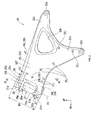
- the head box 20 forms intake passages 20s taking air from the front of the vehicle into the inside when the vehicle is travelling.
- the head box 20 forms the head pipe 21 inclined rearward with respect to the vehicle vertical direction in the side view and forms the intake passages 20s at sides of the head pipe 21.
- a rear end of the head box 20 is connected to the pair of left and right front side frames 22 that first extend rearward and downward from the head pipe 21 and then extend diverging with one rearward and the other downward.
- the front side frames 22 are formed to diverge in the left and right directions from the head pipe 21 in a top view.
- the left and right front side frames 22 first extend from the head pipe 21 curving to extend outward in the vehicle width direction toward the rear sides, next bend rearward, and then extend gradually curving to extend inward in the vehicle width direction toward the rear sides.
- the reference numerals 22L and 22R in the drawings indicate the left front side frame and the right front side frame, respectively.
- an upper pipe portion 21a which has a cylindrical shape that extends such that the diameter increases toward an upper side thereof and then forms an annular circular portion, is formed on an upper end of the head pipe 21.
- a lower pipe portion 21 b which extends such that the diameter increases toward a lower side thereof and then forms an annular circular portion, is formed on a lower end of the head pipe 21.
- a lower end of the upper pipe portion 21 a and an upper end of the lower pipe portion 21 b are respectively connected to an upper end and a lower end of a cylindrical head pipe main body 21 c, which forms the handlebar steering axis C1.
- each of the left and right front side frames 22L and 22R has a rear extension 22d that extends rearward such that the vertical width thereof shortens toward the rear side.
- a first support 22a which supports the front upper portion of the rear cylinder 14, is formed at the tip (rear end) of the rear extension 22d.
- each of the left and right front side frames 22L and 22R has a lower extension 22e that extends downward such that the front-rear width thereof shortens toward the lower side.
- a second support 22b which supports a front lower portion of the front cylinder 13 and a front upper portion of the crankcase 11, is formed at the tip (lower end) of the lower extension 22e.
- each of the left and right front side frames 22L and 22R has a front extension 22f that extends frontward and upward while keeping substantially the same vertical width.
- the tip (front end) of the front extension 22f joins to the rear portion of the head pipe 21.
- the tip of the front extension 22f includes a first circular portion 26 that has an annular shape joined to the upper end of the head pipe 21 (specifically, a lower portion of the upper pipe portion 21 a and the upper end of the head pipe main body 21 c) while circumferentially surrounding the head pipe 21, as well as a second circular portion 27 that has an annular shape joined to the lower end of the head pipe 21 (specifically, an upper portion of the lower pipe portion 21 b and the lower end of the head pipe main body 21 c) while circumferentially surrounding the head pipe 21.
- each of reference numerals 26a and 27a in the drawings indicates a stay mounting portions for attaching a stay that supports a vehicle part for the front of the vehicle such as the front cowl 7a (see Fig. 1 ).
- an upper end edge of each of the left and right front side frames 22L and 22R linearly extends to gradually incline rearward and downward.
- a front lower end edge of each of the left and right front side frames 22L and 22R (specifically, a lower end edge of the front extension 22f and a front end edge of the lower extension 22e) curves to form a convex facing rearward and upward.
- an opening 22h that opens in the vehicle width direction is formed.
- the opening 22h is a through hole that passes through the rear portion of corresponding front side frame in the vehicle width direction.
- the opening 22h has a triangle shape having rounded corners and has a convex portion pointing the first support 22a. This makes it possible to reduce the weight of the left and right front side frames 22L and 22R while keeping rigidities thereof.
- outer walls on the outsides of the left and right front side frames 22L and 22R in the vehicle width direction incline inward in the vehicle width direction toward an upper side.
- mounting bosses 22j are formed for attaching vehicle parts at the sides of the vehicle front portion such as the front side cowl 7b (see Fig. 1 ).
- the multiple (in the present embodiment, seven on the left front side frame 22L illustrated in Fig. 2 ) mounting bosses 22j, which protrude outward in the vehicle width direction from the outer walls of the left and right front side frames 22L and 22R, are disposed with intervals in the front-rear and up-down direction.
- the illustration of the mounting bosses 22j is omitted for convenience.
- mounting protrusions 28 are formed protruding upward for attaching vehicle parts at a vehicle front upper side, such as the fuel tank 8 (see Fig. 1 ).
- a reference numeral 28L in the drawings indicates a left mounting protrusion formed at the center in the front-rear direction of the upper end of the left front side frame 22L
- a reference numeral 28R in the drawings indicates a right mounting protrusion formed at the center in the front-rear direction of the upper end of the right front side frame 22R, respectively.
- the illustration of the left and right mounting protrusions 28L and 28R is omitted for convenience.
- resonators 23 that form resonator chambers 23s reducing the intake noise, first volume portions 24 that form first volume chambers 24s, and second volume portions 25 that form second volume chambers 25s are formed.
- the resonators 23, the first volume portions 24, and the second volume portions 25 are arranged side by side along the handlebar steering axis C1.
- partitions 24w that extend in the vehicle width direction are provided between the first volume chambers 24s and the intake passages 20s to separate the first volume chambers 24s and the intake passages 20s.
- partitions 25w that extend in the vertical direction are provided between the second volume chambers 25s and the intake passages 20s to separate the second volume chambers 25s and the intake passages 20s.
- each of the resonators 23 is disposed at a position adjacent to the upper pipe portion 21 a of the head pipe 21.
- Each of the first volume portions 24 is disposed at a position adjacent to the lower pipe portion 21 b of the head pipe 21.
- each of the second volume portions 25 is disposed between the corresponding resonator 23 and first volume portion 24.
- the resonators 23, the first volume portions 24, and the second volume portions 25 are integrally molded with the head box 20.
- the left and right front side frames 22L and 22R are integrally molded with the head box 20.
- the head box 20 is integrally molded by forging using metals such as aluminum.
- a distance between an upper end of the upper pipe portion 21 a and a lower end of the lower pipe portion 21 b in the head pipe 21 is referred to as an upper-lower length H1 of the head pipe 21.
- a distance between a front upper end and a front lower end (a lower surface of a partition 23w in Fig. 4 ) of each resonator 23 is referred to as an upper-lower length H2 of the resonator 23.
- the upper-lower length H2 of the resonator 23 is shorter than the upper-lower length H1 of the head pipe 21 (H2 ⁇ H1).
- the resonator 23 is disposed at a space within the range of the upper-lower length H1 of the head pipe 21.
- the resonator 23 forms an inner wall 20f of the head box 20 and an outer wall 21f of the head pipe 21. Specifically, the resonator 23 forms the inner wall 20f at a part of the front extension 22f of each of the left and right front side frames 22L and 22R, the part being adjacent to the head pipe 21, as well as the outer wall 21f at the upper pipe portion 21 a of the head pipe 21.
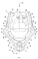
- the resonators 23, the first volume portions 24, and the second volume portions 25 are disposed at both left and right sides of the head box 20. Specifically, in the cross-sectional view in Fig. 3 , the resonators 23, the first volume portions 24, and the second volume portions 25 are formed, one on each of the left and right sides of the vehicle lateral center line CL as a symmetry axis. In the cross-sectional view in Fig. 3 , the resonators 23 and the first volume portions 24 have trapezoidal shapes while the second volume portions 25 have triangular shapes.
- reference numerals 23L, 23R, 24L, 24R, 25L, and 25R in the drawings indicate a left resonator, a right resonator, a left first volume portion, a right first volume portion, a left second volume portion, and a right second volume portion, respectively.
- the intake passages 20s are formed, one on each of the left and right sides of the vehicle lateral center line CL as the symmetry axis.
- the intake passages 20s are formed by being surrounded by partitions (the resonators 23, the first volume portions 24, the second volume portions 25, and head pipe rear partitions 21w formed at a rear side of the head pipe 21) inside the head box 20.
- the rear end of each of the head pipe rear partitions 21w has a curved shape that curves and extends rearward toward the lower side.
- each of the intake passages 20s has a rectangular shape that vertically extends. Note that a reference numeral 21s indicates a space surrounded by the rear portion of the head pipe 21 and the head pipe rear partitions 21w.
- the resonator chambers 23s are formed inside the head box 20 in such a way as to continue to the intake passages 20s.
- the resonator chambers 23s are separately and independently formed on the left and right sides in the head box 20.
- partitions 23w that separate the resonator chambers 23s and the intake passages 20s are provided between the resonator chambers 23s and the intake passages 20s.
- each of the partitions 23w has a thickness in the direction along the handlebar steering axis C1. In a rear side view in Fig.
- the partition 23w inclines and extends from the upper end of the head pipe rear partition 21w downward toward the outside in the vehicle width direction, and then reaches an upper end of partitions 25w.
- a communication hole 23h that opens in the direction along the handlebar steering axis C1 and communicates the resonator chamber 23s and the intake passage 20s is formed.
- the intake passages 20s and the resonator chambers 23s are formed inside the head box 20 without the above-mentioned protrusion. For this reason, since a forming space for the intake passages 20s and the resonator chambers 23s does not need to be given outside the head box 20, size of the front portion of the vehicle body can be effectively reduced compared to the case where the intake passages 20s and the resonator chambers 23s are formed inside the head box 20 having the above-mentioned protrusion.
- the air cleaner box 40 is disposed at a rear side of the head box 20. Referring to Figs. 6 to 8 together, the air cleaner box 40 is formed in a box shape having rounded corners.
- the air cleaner box 40 includes an intake 41 provided with a pair of left and right intake holes 41 h at a front portion thereof, a main body portion 42 provided at a rear side of the intake 41, and an air cleaner element 43 (see Fig. 5 ) that is provided inside the air cleaner box 40 and at a connection between the intake 41 and the main body portion 42.
- the intake 41 includes an intake main body 41 a that has a trapezoidal shape in a front view in Fig. 7 and has a box shape extending such that a left-right width thereof becomes shorter toward a front side thereof in the top view in Fig. 8 , and an intake hole forming portion 41 b that protrudes frontward from a front lower portion of the intake main body 41 a and forms the intake holes 41 h.
- the intake holes 41 h are formed, one on each of the left and right sides of the vehicle lateral center line CL as the symmetry axis.
- each of the pair of left and right intake holes 41 h has a rectangular shape extending vertically. Referring to Fig.
- each of the pair of left and right intake holes 41 h is disposed rearward and downward of the corresponding communication hole 23h.
- the pair of left and right intake holes 41 h are disposed to overlap the pair of left and right intake passages 20s, respectively.
- the main body portion 42 includes an air cleaner box main body 42a that has a box shape extending such that the vertical width thereof becomes shorter toward a rear side thereof in a side view in Fig. 6 , and has a trapezoidal shape having rounded corners in the top view in Fig. 8 , an intake connection 42b positioned at a front side of the air cleaner box main body 42a and connects a rear portion of the intake 41 and the air cleaner box main body 42a, and projecting portions 42c that protrude upward from a top surface of the air cleaner box main body 42a and extend in the front-rear direction in such a way as to incline rearward and downward.
- an air cleaner box main body 42a that has a box shape extending such that the vertical width thereof becomes shorter toward a rear side thereof in a side view in Fig. 6 , and has a trapezoidal shape having rounded corners in the top view in Fig. 8
- an intake connection 42b positioned at a front side of the air cleaner box main body 42a and connects
- the projecting portions 42c are formed, one on each of the left and right sides of the vehicle lateral center line CL as the symmetry axis.
- a space 42m in which vehicle parts such as an engine control unit (ECU) (not illustrated) can be mounted is formed between the pair of left and right projecting portions 42c.
- ECU engine control unit
- the air cleaner box 40 is disposed between the left and right front side frames 22L and 22R, which are the left and right side portions of the main frame 18.
- bosses 42d that have cylindrical shapes and protrude upward are formed.
- bosses 42d are formed at the rear of the space 42m.
- an inside space of the air cleaner box 40 is separated into a dirty side 41s in the intake 41 and a clean side 42s in the main body portion 42 by the air cleaner element 43.
- the dirty side 41s is positioned at an upstream side of the air cleaner element 43, and the clean side 42s is positioned at a downstream side of the air cleaner element 43.
- a front side intake passage forming portion 19 that forms a front side intake passage 19s is provided for taking air from the front of the vehicle.
- the front side intake passage forming portion 19 is disposed at a space surrounded by the front cowl 7a.
- the front side intake passage forming portion 19 first extends and inclines such that a rear side thereof is positioned upward, bends rearward and downward, and then extends to reach a front edge of the head box 20.
- an upper wall 19a of the front side intake passage forming portion 19 first extends and inclines such that a rear side thereof is positioned upward, bends rearward and downward, and then extends to reach the flange 26g of the first circular portion 26.
- a lower wall 19b of the front side intake passage forming portion 19 first extends rearward, further extends and inclines such that a rear side thereof is positioned upward, next bends rearward and upward, after that bends rearward and downward, and then extends to reach the flange 27g of the second circular portion 27.
- the fresh air taken from the outside into the front side intake passage 19s passes through the front side intake passage 19s and the intake passage 20s, and then the air is taken into the intake 41 through the intake hole 41 h.
- the fresh air taken into the dirty side 41 s in the intake 41 first passes through the air cleaner element 43 from a front side to a rear side thereof. Next, the air is filtered and reaches the clean side 42s. After that, the air passes the throttle body 15 and the like. Finally, the air is taken into the cylinder 12.
- a reference numeral W in the drawings indicates a flow of the intake air.
- a resonator structure of the saddle-ride type vehicle includes: the head box 20 that has the head pipe 21 forming the handlebar steering axis C1 and forms the intake passage 20s through which air is taken from the front of the vehicle into the inside of the vehicle when the vehicle is travelling; the air cleaner box 40 that is connected to the head box 20 and allows the air to be taken into the power unit 10 of the vehicle; and the resonator 23 that forms the resonator chamber 23s configured to reduce the intake noise, wherein the resonator chamber 23s is formed inside the head box 20 in such a way as to continue to the intake passage 20s.
- the resonator chamber 23s is formed inside the head box 20 in such a way as to continue to the intake passage 20s, it is possible to effectively use the space inside the main frame 18.
- the size of the front portion of the vehicle body can be reduced unlike the case where the resonator 23 is disposed outside the head box 20.
- the resonator 23 is integrally molded with the head box 20.
- the resonator 23 and head box 20 can be joined seamlessly and the joining surface (surface) becomes smooth.
- the resonator chamber 23s can be formed accurately inside the head box 20.
- any unnecessary portion such as a burr is not made unlike a technique such as welding. Therefore, time and effort to remove the unnecessary portion can be eliminated.
- metal which is a material for forging has a lower thermal expansion rate than resin which is a material for blow molding. Therefore, it is easy to form the resonator chamber 23s accurately inside the head box 20.
- the communication hole 23h through which the resonator chamber 23s and the intake passage 20s communicate is formed in the partition 23w. This enables smooth communication between the resonator chamber 23s and the intake passage 20s. Therefore, it is possible to prevent an intake resistance between the resonator chamber 23s and the intake passage 20s from increasing.
- each of the pair of left and right intake holes 41 h is disposed rearward of the communication hole 23h.
- the air filled in the resonator chamber 23s is smoothly guided into the air cleaner box 40 through the pair of left and right intake holes 41 h. Therefore, the air can be supplied to the power unit 10 by effectively using the air filled in the resonator chamber 23s. Accordingly, it is possible to prevent the intake resistance from increasing at the moment the engine revolution shifts to a high revolution region.
- the resonator 23 is disposed at each of the left and right sides of the head box 20.
- the resonator chambers 23s inside the head box 20 can have a larger volume than in the case where the resonator 23 is disposed at only one side, left or right, of the head box 20. Therefore, the silencing effect for the intake noise can be enhanced.
- a rigidity balance of the left and right main frames 18 including the head box 20 can be improved.
- the upper-lower length H2 of the resonator 23 is shorter than the upper-lower length H1 of the head pipe 21 in the direction along the handlebar steering axis C1.
- the resonator chamber 23s can be compactly formed inside the head box 20, and the size of the front portion of the vehicle body can be reduced.
- the resonator 23 forms the inner wall 20f of the head box 20 and the outer wall 21f of the head pipe 21.
- the volume of the resonator chamber 23s can be increased as large as possible, and the silencing effect for the intake noise can be enhanced.
- left and right front side frames 22L and 22R are integrally molded with the head box 20
- the invention is not limited thereto.
- the left and right front side frames 22L and 22R may be molded separately from the head box 20.
- the left and right front side frames 22L and 22R may be joined mechanically with the head box 20.
- the pair of left and right intake holes 41 h are disposed at the rear lower sides of the communication holes 23h
- the invention is not limited thereto.
- the pair of left and right intake holes 41 h may be arranged at the rear upper sides of the communication holes 23h.
- the pair of left and right intake holes 41 h may be arranged at the rear sides of the communication holes 23h.
- the resonators 23 are arranged at both left and right sides of the head box 20, the invention is not limited thereto.
- the resonator 23 may be arranged at only one side, left or right, of the head box 20.
- the upper-lower length H2 of the resonator 23 is shorter than the upper-lower length H1 of the head pipe 21 in the direction along the handlebar steering axis C1
- the invention is not limited thereto.
- the upper-lower length H2 of the resonator 23 may be longer than or equal to the upper-lower length H1 of the head pipe 21 in the direction along the handlebar steering axis C1.
- the resonator 23 forms the inner wall 20f of the head box 20 and the outer wall 21f of the head pipe 21, the invention is not limited thereto.
- the resonator 23 does not have to form the inner wall 20f of the head box 20 and the outer wall 21f of the head pipe 21.
- the left and right resonator chambers 23s may be formed to connect each other (as to be converged) inside the head box 20.
- the resonator 23 forms the resonator chamber 23s and disposed at the position adjacent to the upper pipe portion 21a of the head pipe 21
- the first volume portion 24 forms the first volume chamber 24s and disposed at the position adjacent to the lower pipe portion 21b of the head pipe 21
- the second volume portion 25 forms the second volume chamber 25s and disposed between the resonator 23 and the first volume chamber 24 at the side of the head pipe main body 21 c
- the invention is not limited thereto.
- at least one of the first volume portion 24 and the second volume portion 25 may be given a function as a resonator.
- the volume of the resonator chamber 23s inside the head box 20 can be increased. Therefore, the silencing effect for the intake noise can be enhanced.
- the resonator 23 may be formed at the upper portion of the center in the front-rear direction of the head box 20. In other words, the resonator 23 may be formed at the upper portion of the head box 20. In addition, the resonator 23 may be formed not at the top portion of the head box 20 but at the lower portion of the head box 20.
- the vehicle body frame 2 is divided into the main frame 18 as the vehicle body front frame and the seat rail 30 as the vehicle body rear frame (divided into the front and the rear), the invention is not limited thereto.
- the vehicle body frame 2 does not have to be divided in the front and the rear.
- the vehicle body frame 2 may be one body including the front and the rear.
- the saddle-ride type vehicle includes various kinds of vehicles that a driver rides astride of, such as not only motorcycles (including motor-assisted bicycles and scooter type vehicles) but also three-wheeled vehicles (including one front wheel and two rear wheels types as well as two front wheels and one rear wheel types).
- the present invention is applicable to not only motorcycles but also four-wheeled vehicles such as automobiles.
- the engine in the embodiment is a V-type four-cylinder engine
- the engine may be a two-cylinder engine or a six-cylinder engine
- the cylinder arrangements are not limited to the V-type and may be a horizontally-opposed cylinder type, for example.
- the engine does not need to be what is called a transverse engine, which is mounted such that a crankshaft is parallel to the vehicle width direction.
- the engine may be what is called a longitudinal engine, which is mounted such that the crankshaft is parallel to the vehicle front-rear direction, and the cylinder arrangement in this case may also include various types.
- the power unit 10 may be one that includes an electric motor in the drive source.
Landscapes
- Engineering & Computer Science (AREA)
- Mechanical Engineering (AREA)
- Chemical & Material Sciences (AREA)
- Combustion & Propulsion (AREA)
- General Engineering & Computer Science (AREA)
- Transportation (AREA)
- Automatic Cycles, And Cycles In General (AREA)
Applications Claiming Priority (1)
| Application Number | Priority Date | Filing Date | Title |
|---|---|---|---|
| JP2015189078A JP6455981B2 (ja) | 2015-09-28 | 2015-09-28 | 鞍乗型車両のレゾネータ構造 |
Publications (2)
| Publication Number | Publication Date |
|---|---|
| EP3147191A1 true EP3147191A1 (de) | 2017-03-29 |
| EP3147191B1 EP3147191B1 (de) | 2019-12-18 |
Family
ID=56682041
Family Applications (1)
| Application Number | Title | Priority Date | Filing Date |
|---|---|---|---|
| EP16183770.3A Active EP3147191B1 (de) | 2015-09-28 | 2016-08-11 | Resonatorstruktur für ein sattelfahrzeug |
Country Status (3)
| Country | Link |
|---|---|
| US (1) | US9739245B2 (de) |
| EP (1) | EP3147191B1 (de) |
| JP (1) | JP6455981B2 (de) |
Cited By (1)
| Publication number | Priority date | Publication date | Assignee | Title |
|---|---|---|---|---|
| CN108361130A (zh) * | 2018-01-26 | 2018-08-03 | 重庆隆鑫机车有限公司 | 高位进气的空滤系统及三轮车 |
Families Citing this family (11)
| Publication number | Priority date | Publication date | Assignee | Title |
|---|---|---|---|---|
| CN108602423B (zh) | 2016-02-01 | 2021-08-13 | 康明斯公司 | 具有气流通道的附件支撑托架 |
| US10352281B2 (en) * | 2016-07-08 | 2019-07-16 | Kawasaki Jukogyo Kabushiki Kaisha | Manufacturing method of head box of motorcycle, and air-intake device of motorcycle |
| JP6456991B2 (ja) * | 2017-02-27 | 2019-01-23 | 本田技研工業株式会社 | 自動車用エアクリーナの吸気構造 |
| EP4212423A1 (de) * | 2017-03-10 | 2023-07-19 | Indian Motorcycle International, LLC | Zweirädriges fahrzeug |
| US10655536B1 (en) | 2017-05-24 | 2020-05-19 | Indian Motorcycle International, LLC | Engine |
| US10589621B1 (en) * | 2017-05-24 | 2020-03-17 | Indian Motorcycle International, LLC | Two-wheeled vehicle |
| US10371249B1 (en) | 2017-05-24 | 2019-08-06 | Indian Motorcycle International, LLC | Engine |
| JP7058092B2 (ja) * | 2017-09-11 | 2022-04-21 | カワサキモータース株式会社 | 鞍乗型車両 |
| US10843759B2 (en) * | 2017-10-25 | 2020-11-24 | Yamaha Hatsudoki Kabushiki Kaisha | Vehicle |
| USD911879S1 (en) | 2018-09-10 | 2021-03-02 | Indian Motorcycle International, LLC | Motorcycle |
| US11077910B2 (en) | 2018-09-28 | 2021-08-03 | Indian Motorcycle International, LLC | Two-wheeled vehicle |
Citations (2)
| Publication number | Priority date | Publication date | Assignee | Title |
|---|---|---|---|---|
| JP2010127076A (ja) | 2008-11-25 | 2010-06-10 | Yamaha Motor Co Ltd | 車両 |
| US20150027797A1 (en) * | 2013-07-24 | 2015-01-29 | Honda Motor Co., Ltd. | Straddle type vehicle |
Family Cites Families (16)
| Publication number | Priority date | Publication date | Assignee | Title |
|---|---|---|---|---|
| JP3862464B2 (ja) * | 1999-09-07 | 2006-12-27 | 本田技研工業株式会社 | 自動2輪車用エアクリーナ装置 |
| JP3122437B1 (ja) * | 1999-09-21 | 2001-01-09 | 川崎重工業株式会社 | 車両用エンジンの吸気装置 |
| JP3723792B2 (ja) * | 2002-09-13 | 2005-12-07 | 川崎重工業株式会社 | 車両用エンジンの空気取入装置 |
| JP4340500B2 (ja) * | 2003-09-09 | 2009-10-07 | 川崎重工業株式会社 | 自動二輪車の吸気装置 |
| JP4490203B2 (ja) * | 2004-08-09 | 2010-06-23 | 川崎重工業株式会社 | 自動二輪車の吸気装置 |
| JP4444868B2 (ja) * | 2005-03-31 | 2010-03-31 | 本田技研工業株式会社 | 吸気ダクト構造 |
| JP2007145130A (ja) * | 2005-11-25 | 2007-06-14 | Yamaha Motor Co Ltd | 自動二輪車 |
| JP4745175B2 (ja) * | 2005-12-28 | 2011-08-10 | 本田技研工業株式会社 | 自動二輪車 |
| US7748746B2 (en) * | 2007-01-17 | 2010-07-06 | Polaris Industries Inc. | Fuel tank arrangement for a vehicle |
| JP5534744B2 (ja) * | 2008-09-19 | 2014-07-02 | 川崎重工業株式会社 | ラムダクトユニット |
| JP2010095245A (ja) * | 2008-09-19 | 2010-04-30 | Kawasaki Heavy Ind Ltd | 吸音構造を持つラムダクトユニット |
| US8162101B2 (en) * | 2008-09-19 | 2012-04-24 | Kawasaki Jukogyo Kabushiki Kaisha | Ram intake unit having a sound absorbing structure |
| JP5129712B2 (ja) * | 2008-09-30 | 2013-01-30 | 本田技研工業株式会社 | 自動二輪車のラジエータ取付け構造 |
| JP5897985B2 (ja) * | 2012-05-17 | 2016-04-06 | 本田技研工業株式会社 | 自動二輪車における前部導風構造 |
| JP5965270B2 (ja) * | 2012-09-28 | 2016-08-03 | 本田技研工業株式会社 | 自動二輪車における前部導風構造 |
| JP6232960B2 (ja) * | 2013-11-18 | 2017-11-22 | スズキ株式会社 | 自動二輪車の吸気ダクト装置 |
-
2015
- 2015-09-28 JP JP2015189078A patent/JP6455981B2/ja active Active
-
2016
- 2016-08-11 EP EP16183770.3A patent/EP3147191B1/de active Active
- 2016-08-17 US US15/239,094 patent/US9739245B2/en active Active
Patent Citations (2)
| Publication number | Priority date | Publication date | Assignee | Title |
|---|---|---|---|---|
| JP2010127076A (ja) | 2008-11-25 | 2010-06-10 | Yamaha Motor Co Ltd | 車両 |
| US20150027797A1 (en) * | 2013-07-24 | 2015-01-29 | Honda Motor Co., Ltd. | Straddle type vehicle |
Cited By (2)
| Publication number | Priority date | Publication date | Assignee | Title |
|---|---|---|---|---|
| CN108361130A (zh) * | 2018-01-26 | 2018-08-03 | 重庆隆鑫机车有限公司 | 高位进气的空滤系统及三轮车 |
| CN108361130B (zh) * | 2018-01-26 | 2023-08-25 | 重庆隆鑫机车有限公司 | 高位进气的空滤系统及三轮车 |
Also Published As
| Publication number | Publication date |
|---|---|
| US9739245B2 (en) | 2017-08-22 |
| EP3147191B1 (de) | 2019-12-18 |
| JP2017065271A (ja) | 2017-04-06 |
| JP6455981B2 (ja) | 2019-01-23 |
| US20170089308A1 (en) | 2017-03-30 |
Similar Documents
| Publication | Publication Date | Title |
|---|---|---|
| EP3147191B1 (de) | Resonatorstruktur für ein sattelfahrzeug | |
| US8443925B2 (en) | Motorcycle | |
| EP3061933B1 (de) | Auspuffstruktur eines grätschsitzfahrzeugs | |
| US7637342B2 (en) | Straddle type vehicle | |
| US9272747B2 (en) | Body frame of motorcycle and method for manufacturing the body frame | |
| US9428238B2 (en) | Body frame structure for saddle type vehicle | |
| EP3381780B1 (de) | Fahrzeugrahmenstruktur eines sattelfahrzeugs | |
| CN110431070B (zh) | 跨骑型车辆的车身结构 | |
| EP3147190B1 (de) | Sattelfahrzeug | |
| JP6827350B2 (ja) | 鞍乗り型車両 | |
| US20180272857A1 (en) | Body structure of saddle riding vehicle | |
| EP2711277B1 (de) | Rahmenstruktur für Sattel-Kraftfahrzeug | |
| WO2021065733A1 (ja) | 鞍乗型車両のエアクリーナ構造 | |
| JP6351172B2 (ja) | 車体後部構造 | |
| CN104234883A (zh) | 摩托车的空气净化器结构 | |
| JP7454532B2 (ja) | 鞍乗型車両 | |
| CN220687438U (zh) | 排气消声器装置以及鞍乘型车辆 | |
| WO2010038586A1 (ja) | 自動二輪車のエンジン懸架構造 | |
| JP7089407B2 (ja) | 鞍乗型車両 | |
| JP5843813B2 (ja) | 自動二輪車の吸気構造 | |
| JP2003170882A (ja) | 自動二輪車のフレーム構造 | |
| JP3159286U (ja) | 鞍乗型車両 |
Legal Events
| Date | Code | Title | Description |
|---|---|---|---|
| PUAI | Public reference made under article 153(3) epc to a published international application that has entered the european phase |
Free format text: ORIGINAL CODE: 0009012 |
|
| STAA | Information on the status of an ep patent application or granted ep patent |
Free format text: STATUS: REQUEST FOR EXAMINATION WAS MADE |
|
| 17P | Request for examination filed |
Effective date: 20160811 |
|
| AK | Designated contracting states |
Kind code of ref document: A1 Designated state(s): AL AT BE BG CH CY CZ DE DK EE ES FI FR GB GR HR HU IE IS IT LI LT LU LV MC MK MT NL NO PL PT RO RS SE SI SK SM TR |
|
| AX | Request for extension of the european patent |
Extension state: BA ME |
|
| STAA | Information on the status of an ep patent application or granted ep patent |
Free format text: STATUS: EXAMINATION IS IN PROGRESS |
|
| 17Q | First examination report despatched |
Effective date: 20180405 |
|
| GRAP | Despatch of communication of intention to grant a patent |
Free format text: ORIGINAL CODE: EPIDOSNIGR1 |
|
| STAA | Information on the status of an ep patent application or granted ep patent |
Free format text: STATUS: GRANT OF PATENT IS INTENDED |
|
| INTG | Intention to grant announced |
Effective date: 20190704 |
|
| GRAS | Grant fee paid |
Free format text: ORIGINAL CODE: EPIDOSNIGR3 |
|
| GRAA | (expected) grant |
Free format text: ORIGINAL CODE: 0009210 |
|
| STAA | Information on the status of an ep patent application or granted ep patent |
Free format text: STATUS: THE PATENT HAS BEEN GRANTED |
|
| AK | Designated contracting states |
Kind code of ref document: B1 Designated state(s): AL AT BE BG CH CY CZ DE DK EE ES FI FR GB GR HR HU IE IS IT LI LT LU LV MC MK MT NL NO PL PT RO RS SE SI SK SM TR |
|
| REG | Reference to a national code |
Ref country code: CH Ref legal event code: EP |
|
| REG | Reference to a national code |
Ref country code: IE Ref legal event code: FG4D |
|
| REG | Reference to a national code |
Ref country code: DE Ref legal event code: R096 Ref document number: 602016026281 Country of ref document: DE |
|
| REG | Reference to a national code |
Ref country code: AT Ref legal event code: REF Ref document number: 1214312 Country of ref document: AT Kind code of ref document: T Effective date: 20200115 |
|
| REG | Reference to a national code |
Ref country code: NL Ref legal event code: MP Effective date: 20191218 |
|
| PG25 | Lapsed in a contracting state [announced via postgrant information from national office to epo] |
Ref country code: FI Free format text: LAPSE BECAUSE OF FAILURE TO SUBMIT A TRANSLATION OF THE DESCRIPTION OR TO PAY THE FEE WITHIN THE PRESCRIBED TIME-LIMIT Effective date: 20191218 Ref country code: GR Free format text: LAPSE BECAUSE OF FAILURE TO SUBMIT A TRANSLATION OF THE DESCRIPTION OR TO PAY THE FEE WITHIN THE PRESCRIBED TIME-LIMIT Effective date: 20200319 Ref country code: LV Free format text: LAPSE BECAUSE OF FAILURE TO SUBMIT A TRANSLATION OF THE DESCRIPTION OR TO PAY THE FEE WITHIN THE PRESCRIBED TIME-LIMIT Effective date: 20191218 Ref country code: NO Free format text: LAPSE BECAUSE OF FAILURE TO SUBMIT A TRANSLATION OF THE DESCRIPTION OR TO PAY THE FEE WITHIN THE PRESCRIBED TIME-LIMIT Effective date: 20200318 Ref country code: SE Free format text: LAPSE BECAUSE OF FAILURE TO SUBMIT A TRANSLATION OF THE DESCRIPTION OR TO PAY THE FEE WITHIN THE PRESCRIBED TIME-LIMIT Effective date: 20191218 Ref country code: LT Free format text: LAPSE BECAUSE OF FAILURE TO SUBMIT A TRANSLATION OF THE DESCRIPTION OR TO PAY THE FEE WITHIN THE PRESCRIBED TIME-LIMIT Effective date: 20191218 Ref country code: BG Free format text: LAPSE BECAUSE OF FAILURE TO SUBMIT A TRANSLATION OF THE DESCRIPTION OR TO PAY THE FEE WITHIN THE PRESCRIBED TIME-LIMIT Effective date: 20200318 |
|
| REG | Reference to a national code |
Ref country code: LT Ref legal event code: MG4D |
|
| PG25 | Lapsed in a contracting state [announced via postgrant information from national office to epo] |
Ref country code: HR Free format text: LAPSE BECAUSE OF FAILURE TO SUBMIT A TRANSLATION OF THE DESCRIPTION OR TO PAY THE FEE WITHIN THE PRESCRIBED TIME-LIMIT Effective date: 20191218 Ref country code: RS Free format text: LAPSE BECAUSE OF FAILURE TO SUBMIT A TRANSLATION OF THE DESCRIPTION OR TO PAY THE FEE WITHIN THE PRESCRIBED TIME-LIMIT Effective date: 20191218 |
|
| PG25 | Lapsed in a contracting state [announced via postgrant information from national office to epo] |
Ref country code: AL Free format text: LAPSE BECAUSE OF FAILURE TO SUBMIT A TRANSLATION OF THE DESCRIPTION OR TO PAY THE FEE WITHIN THE PRESCRIBED TIME-LIMIT Effective date: 20191218 |
|
| PG25 | Lapsed in a contracting state [announced via postgrant information from national office to epo] |
Ref country code: EE Free format text: LAPSE BECAUSE OF FAILURE TO SUBMIT A TRANSLATION OF THE DESCRIPTION OR TO PAY THE FEE WITHIN THE PRESCRIBED TIME-LIMIT Effective date: 20191218 Ref country code: NL Free format text: LAPSE BECAUSE OF FAILURE TO SUBMIT A TRANSLATION OF THE DESCRIPTION OR TO PAY THE FEE WITHIN THE PRESCRIBED TIME-LIMIT Effective date: 20191218 Ref country code: PT Free format text: LAPSE BECAUSE OF FAILURE TO SUBMIT A TRANSLATION OF THE DESCRIPTION OR TO PAY THE FEE WITHIN THE PRESCRIBED TIME-LIMIT Effective date: 20200513 Ref country code: CZ Free format text: LAPSE BECAUSE OF FAILURE TO SUBMIT A TRANSLATION OF THE DESCRIPTION OR TO PAY THE FEE WITHIN THE PRESCRIBED TIME-LIMIT Effective date: 20191218 Ref country code: RO Free format text: LAPSE BECAUSE OF FAILURE TO SUBMIT A TRANSLATION OF THE DESCRIPTION OR TO PAY THE FEE WITHIN THE PRESCRIBED TIME-LIMIT Effective date: 20191218 |
|
| PG25 | Lapsed in a contracting state [announced via postgrant information from national office to epo] |
Ref country code: SM Free format text: LAPSE BECAUSE OF FAILURE TO SUBMIT A TRANSLATION OF THE DESCRIPTION OR TO PAY THE FEE WITHIN THE PRESCRIBED TIME-LIMIT Effective date: 20191218 Ref country code: IS Free format text: LAPSE BECAUSE OF FAILURE TO SUBMIT A TRANSLATION OF THE DESCRIPTION OR TO PAY THE FEE WITHIN THE PRESCRIBED TIME-LIMIT Effective date: 20200418 Ref country code: SK Free format text: LAPSE BECAUSE OF FAILURE TO SUBMIT A TRANSLATION OF THE DESCRIPTION OR TO PAY THE FEE WITHIN THE PRESCRIBED TIME-LIMIT Effective date: 20191218 |
|
| REG | Reference to a national code |
Ref country code: DE Ref legal event code: R097 Ref document number: 602016026281 Country of ref document: DE |
|
| REG | Reference to a national code |
Ref country code: AT Ref legal event code: MK05 Ref document number: 1214312 Country of ref document: AT Kind code of ref document: T Effective date: 20191218 |
|
| PLBE | No opposition filed within time limit |
Free format text: ORIGINAL CODE: 0009261 |
|
| STAA | Information on the status of an ep patent application or granted ep patent |
Free format text: STATUS: NO OPPOSITION FILED WITHIN TIME LIMIT |
|
| PG25 | Lapsed in a contracting state [announced via postgrant information from national office to epo] |
Ref country code: DK Free format text: LAPSE BECAUSE OF FAILURE TO SUBMIT A TRANSLATION OF THE DESCRIPTION OR TO PAY THE FEE WITHIN THE PRESCRIBED TIME-LIMIT Effective date: 20191218 Ref country code: ES Free format text: LAPSE BECAUSE OF FAILURE TO SUBMIT A TRANSLATION OF THE DESCRIPTION OR TO PAY THE FEE WITHIN THE PRESCRIBED TIME-LIMIT Effective date: 20191218 |
|
| 26N | No opposition filed |
Effective date: 20200921 |
|
| PG25 | Lapsed in a contracting state [announced via postgrant information from national office to epo] |
Ref country code: AT Free format text: LAPSE BECAUSE OF FAILURE TO SUBMIT A TRANSLATION OF THE DESCRIPTION OR TO PAY THE FEE WITHIN THE PRESCRIBED TIME-LIMIT Effective date: 20191218 Ref country code: SI Free format text: LAPSE BECAUSE OF FAILURE TO SUBMIT A TRANSLATION OF THE DESCRIPTION OR TO PAY THE FEE WITHIN THE PRESCRIBED TIME-LIMIT Effective date: 20191218 |
|
| PG25 | Lapsed in a contracting state [announced via postgrant information from national office to epo] |
Ref country code: IT Free format text: LAPSE BECAUSE OF FAILURE TO SUBMIT A TRANSLATION OF THE DESCRIPTION OR TO PAY THE FEE WITHIN THE PRESCRIBED TIME-LIMIT Effective date: 20191218 |
|
| PG25 | Lapsed in a contracting state [announced via postgrant information from national office to epo] |
Ref country code: PL Free format text: LAPSE BECAUSE OF FAILURE TO SUBMIT A TRANSLATION OF THE DESCRIPTION OR TO PAY THE FEE WITHIN THE PRESCRIBED TIME-LIMIT Effective date: 20191218 |
|
| REG | Reference to a national code |
Ref country code: DE Ref legal event code: R119 Ref document number: 602016026281 Country of ref document: DE |
|
| PG25 | Lapsed in a contracting state [announced via postgrant information from national office to epo] |
Ref country code: MC Free format text: LAPSE BECAUSE OF FAILURE TO SUBMIT A TRANSLATION OF THE DESCRIPTION OR TO PAY THE FEE WITHIN THE PRESCRIBED TIME-LIMIT Effective date: 20191218 |
|
| REG | Reference to a national code |
Ref country code: CH Ref legal event code: PL |
|
| GBPC | Gb: european patent ceased through non-payment of renewal fee |
Effective date: 20200811 |
|
| PG25 | Lapsed in a contracting state [announced via postgrant information from national office to epo] |
Ref country code: CH Free format text: LAPSE BECAUSE OF NON-PAYMENT OF DUE FEES Effective date: 20200831 Ref country code: LI Free format text: LAPSE BECAUSE OF NON-PAYMENT OF DUE FEES Effective date: 20200831 Ref country code: LU Free format text: LAPSE BECAUSE OF NON-PAYMENT OF DUE FEES Effective date: 20200811 |
|
| REG | Reference to a national code |
Ref country code: BE Ref legal event code: MM Effective date: 20200831 |
|
| PG25 | Lapsed in a contracting state [announced via postgrant information from national office to epo] |
Ref country code: DE Free format text: LAPSE BECAUSE OF NON-PAYMENT OF DUE FEES Effective date: 20210302 Ref country code: FR Free format text: LAPSE BECAUSE OF NON-PAYMENT OF DUE FEES Effective date: 20200831 |
|
| PG25 | Lapsed in a contracting state [announced via postgrant information from national office to epo] |
Ref country code: GB Free format text: LAPSE BECAUSE OF NON-PAYMENT OF DUE FEES Effective date: 20200811 Ref country code: IE Free format text: LAPSE BECAUSE OF NON-PAYMENT OF DUE FEES Effective date: 20200811 Ref country code: BE Free format text: LAPSE BECAUSE OF NON-PAYMENT OF DUE FEES Effective date: 20200831 |
|
| PG25 | Lapsed in a contracting state [announced via postgrant information from national office to epo] |
Ref country code: TR Free format text: LAPSE BECAUSE OF FAILURE TO SUBMIT A TRANSLATION OF THE DESCRIPTION OR TO PAY THE FEE WITHIN THE PRESCRIBED TIME-LIMIT Effective date: 20191218 Ref country code: MT Free format text: LAPSE BECAUSE OF FAILURE TO SUBMIT A TRANSLATION OF THE DESCRIPTION OR TO PAY THE FEE WITHIN THE PRESCRIBED TIME-LIMIT Effective date: 20191218 Ref country code: CY Free format text: LAPSE BECAUSE OF FAILURE TO SUBMIT A TRANSLATION OF THE DESCRIPTION OR TO PAY THE FEE WITHIN THE PRESCRIBED TIME-LIMIT Effective date: 20191218 |
|
| PG25 | Lapsed in a contracting state [announced via postgrant information from national office to epo] |
Ref country code: MK Free format text: LAPSE BECAUSE OF FAILURE TO SUBMIT A TRANSLATION OF THE DESCRIPTION OR TO PAY THE FEE WITHIN THE PRESCRIBED TIME-LIMIT Effective date: 20191218 |