EP3144420A1 - Reinigungsvorrichtung für eine verdichtungsvorrichtung - Google Patents
Reinigungsvorrichtung für eine verdichtungsvorrichtung Download PDFInfo
- Publication number
- EP3144420A1 EP3144420A1 EP16185820.4A EP16185820A EP3144420A1 EP 3144420 A1 EP3144420 A1 EP 3144420A1 EP 16185820 A EP16185820 A EP 16185820A EP 3144420 A1 EP3144420 A1 EP 3144420A1
- Authority
- EP
- European Patent Office
- Prior art keywords
- cleaning
- rotation
- cleaning device
- drive element
- axis
- Prior art date
- Legal status (The legal status is an assumption and is not a legal conclusion. Google has not performed a legal analysis and makes no representation as to the accuracy of the status listed.)
- Granted
Links
- 238000004140 cleaning Methods 0.000 title claims abstract description 65
- 238000005056 compaction Methods 0.000 title description 3
- 239000000835 fiber Substances 0.000 claims abstract description 34
- 238000007790 scraping Methods 0.000 claims description 20
- 238000009987 spinning Methods 0.000 claims description 12
- 239000002657 fibrous material Substances 0.000 description 12
- 238000007906 compression Methods 0.000 description 11
- 230000006835 compression Effects 0.000 description 9
- 230000000694 effects Effects 0.000 description 4
- 238000012423 maintenance Methods 0.000 description 3
- 238000007378 ring spinning Methods 0.000 description 3
- 230000002411 adverse Effects 0.000 description 2
- 230000005540 biological transmission Effects 0.000 description 2
- 238000000280 densification Methods 0.000 description 2
- 238000000034 method Methods 0.000 description 2
- 230000002093 peripheral effect Effects 0.000 description 2
- 239000004952 Polyamide Substances 0.000 description 1
- 238000009825 accumulation Methods 0.000 description 1
- 239000000853 adhesive Substances 0.000 description 1
- 230000001070 adhesive effect Effects 0.000 description 1
- 230000007547 defect Effects 0.000 description 1
- 238000006073 displacement reaction Methods 0.000 description 1
- 229920002647 polyamide Polymers 0.000 description 1
- 229910000679 solder Inorganic materials 0.000 description 1
Images


Classifications
-
- D—TEXTILES; PAPER
- D01—NATURAL OR MAN-MADE THREADS OR FIBRES; SPINNING
- D01H—SPINNING OR TWISTING
- D01H11/00—Arrangements for confining or removing dust, fly or the like
-
- D—TEXTILES; PAPER
- D01—NATURAL OR MAN-MADE THREADS OR FIBRES; SPINNING
- D01H—SPINNING OR TWISTING
- D01H5/00—Drafting machines or arrangements ; Threading of roving into drafting machine
- D01H5/18—Drafting machines or arrangements without fallers or like pinned bars
- D01H5/70—Constructional features of drafting elements
- D01H5/72—Fibre-condensing guides
Definitions
- the invention relates to a cleaning device for a compacting device with a drive element and a rotatably mounted about a rotation axis fiber processing element with an approach, wherein the approach with the drive element cooperates and forms a gear stage, which is designed such that the neck and the drive element with a rotate at different speeds.
- a disadvantage of the device according to the WO 2012068692 A1 is that during the compression process, individual fibers to be separated from the fiber material to be compacted and deposited on the circumference of the compression element. These fibers can move in the direction of the outer end face of the compression element up to the drive element. The movement of the fibers can be generated for example by the rotation of the compression element or by the resulting during rotation of the compression element air flow. There is a risk that fibers that reach the outer end side of the drive element, move up to the outer periphery of the approach and attach to this.
- the invention is thus based on the object, a compacting device for compacting a fiber material on a spinning machine in such a way that fibers which detach during the compression process of the fiber material to be compacted, do not deposit in the region of the outer end face of the drive element.
- the cleaning device comprises a cleaning element which is arranged in the direction of the axis of rotation on a side facing away from the fiber processing element end face of the drive element and is rotatably connected to the approach, wherein the cleaning element at least one scraping edge which runs in a plane parallel to the end face of the drive element and in its course has an increasing distance from the axis of rotation.
- the wiping edge of the cleaning element has the advantageous functional effect that those fibers which reach the outer end side of the drive element are stripped directly from the wiping edge of the cleaning element, so that these fibers no longer move to the outer periphery of the approach and settle on this can.
- the compaction device can be operated continuously and therefore there is no need for maintenance and no high downtime of the spinning machine must be taken into account. Accordingly, a higher productivity in compacting the fiber material can be achieved for the known compacting device with the cleaning device according to the invention having a scraping edge.
- the wiping edge at least partially projects beyond the projection in the radial direction to the axis of rotation. This has the advantageous effect that seen in the direction of rotation of the cleaning element, the wiping edge optimally strip the fibers on the front side of the drive element.
- the rotationally fixed connection of the cleaning element with the approach is a snap connection.
- the snap connection has the advantage that, for a replacement of the cleaning element - in case of defect - no tool is necessary because the replacement can rather be done manually.
- the replacement with the snap connection is quick and easy.
- the rotationally fixed connection of the cleaning element with the approach could be a screw, rivet or adhesive connection.
- these connection techniques are conceivable, they are rather impractical when mounted as well as exchanged.
- the cleaning element on several scraping edges, which are arranged in a star shape.
- the majority of star-shaped scraping edges has the advantage that seen in the direction of rotation of the cleaning element, the scraping edges optimally strip the fibers on the end face of the drive element.
- the star-shaped arrangement also allows a nationwide cleaning of the fibers on the front side of the drive element. In this way, an accumulation of the fibers on the outer circumference of the neck is at least approximately completely prevented.
- the cleaning element has three scraping edges.
- the cleaning element is preferably formed as an equilateral triangle, so that the three stripping edges seen in the direction of rotation strip the fibers on the end face of the drive element offset by 120 ° to each other.
- the cleaning element on four scraping edges.
- the cleaning element is preferably formed as a rhombus, so that the four stripping edges seen in the direction of rotation strip the fibers on the front side of the drive element offset by 90 ° to each other.
- the scraping edge is concave. This has the advantageous effect that seen in the direction of rotation of the cleaning element, the fibers are transported in front of the scraping edge. In this way, an optimal removal of the fibers along the concave scraper edge is possible.
- FIG. 1 shows a schematic side view of a spinning station 10 of a spinning machine (ring spinning machine) with a drafting unit 12, which is provided with an input roller pair 14, 16, a middle roller pair 18, 20 and a pair of output rollers 22, 24.
- the lower roller pairs 14, 18, 22 are, as indicated schematically, connected to a drive A.
- the upper pairs of rollers 16, 20, 24 are designed as pressure rollers and rotatably mounted on a pivotally mounted pressure arm 19.
- the pressure arm 19 is pivotally mounted about an axis 21 and is acted upon by a spring element F.
- the peripheral speed of the driven roller 18 is slightly higher than the peripheral speed of the driven roller 14.
- a fiber material supplied to the drafting unit 12 is subjected to a preliminary delay in the form of a sliver L between the pair of input rollers 14, 16 and the middle roller pair 18, 20.
- the main distortion of the fiber material L occurs between the middle roller pair 18, 20 and the pair of output rollers 22, 24, wherein the output roller 22 has a substantially higher rotational speed than the center roller 18.
- the drawn out by the pair of output rollers 22, 24 stretched fiber V is deflected downward and enters the region of a suction zone SZ a subsequent fiber processing device in the form of a suction drum 26 as part of a compacting device VM.
- the suction drum 26 is rotatably mounted in the region of its outer end on a shaft 28 having a rotation axis 34.
- the shaft 28 is fixed in a receptacle 29 of a carrier 32.
- the shaft 28 has a somewhat larger diameter in the region of the receptacle 29, while the ends of the shaft 28, which extend from this receptacle 29 to both sides, have a tapered diameter and serve to receive bearings.
- the rotatable mounting of the suction drum 26 will be discussed below FIG. 3 explained in detail.
- the carrier 32 is provided at its end facing the spinning machine with a U-shaped or fork-shaped end piece 38, which rests with its inner surface on a portion of the outer circumference of a suction tube 40.
- the suction tube 40 is connected via one or more connecting channels 42 with a central main channel 44.
- This main channel 44 is connected to a negative pressure source SP, which can be controlled via a control unit ST.
- a pinch roller 46 which rests on the suction drum 26 via a pressure load and forms a nip line P with this.
- the pinch roller 46 is rotatably mounted on an axle 48, which is attached to a bearing element 50 which is connected by screws 52 (or other fasteners) with a spring element 54.
- the spring element 54 is fastened to the carrier 32 via schematically illustrated screws 52 (or other fastening elements).
- the nip P at the same time forms a so-called "rotation lock gap", from which the fiber material in the conveying direction FS in the form of a compressed yarn FK is supplied under rotation distribution of a ring spinning device shown schematically.
- This is provided with a ring 56 and a rotor 58, wherein the yarn is wound on a sleeve 60 to form a coil 62 (Kops).
- a yarn guide 64 is arranged between the nip line P and the rotor 58.
- the ring 56 is attached to a ring frame 66 which performs an up and down movement during the spinning process.
- the suction drum 26 is in a working position in which the outer circumference U of a drive element in the form of a friction wheel 70 via a correspondingly applied pressure load on the outer circumference U7 of the driven output roller 22 rests.
- the friction wheel 70 is driven by friction from the output roller 22 in a first gear stage G1.
- the friction wheel 70 likewise transmits the drive in a second gear stage G2 to an annular shoulder 72 of the suction drum 26 via friction. This occurs at the location where the inner surface IF with the inner diameter D2 of the friction wheel 70 and the outer circumference AU of the projection 72 with the Touch outer diameter D1 or lie on top of each other.
- the axis of rotation of the friction wheel 70 is offset axially parallel to the axis of rotation 34 of the projection 72, so that rotates with respect to the second gear stage G2 driven by the output roller 22 friction wheel 70 at a different speed as the suction drum 26.
- a circular cap in the direction of the axis of rotation 34 on one of the suction drum 26 facing away from end face 82 of the friction wheel 70 is disposed in the prior art and rotatably connected to the neck 72.
- individual fibers can detach from the fiber material V to be compacted, deposit on the circumference of the suction drum 26 and move in the direction of the end face 82 of the friction wheel 70 and thus reach the axial gap between the end face 82 of the friction wheel 70 and the circular cover cap ,
- the movement of the fibers can be e.g. be generated by the rotation of the suction drum 26 or the resulting during rotation of the suction drum 26 air flow. In this case, there is a risk that fibers that reach the axial gap, move up to the outer circumference AU of the neck 72 and attach to this.
- a cleaning element 76 according to the invention is used instead of the circular cover cap, as shown purely schematically in dashed lines in FIG. Accordingly, the cleaning element 76 according to the invention is arranged in the direction of the axis of rotation 34 on the end face 82 of the friction wheel 70 facing away from the screen drum 26 and connected in a rotationally fixed manner to the projection 72. Consequently, the cleaning element 76 rotates at the same speed as the suction drum 26 and different from the friction wheel 70, wherein all elements 70, 72, 76 are driven in the same direction of rotation.
- the cleaning element 76 is made of polyamide type PA12 and has opaque properties. This means that the cleaning element is preferably transparent, translucent or clear-sighted. Thus, by the Cleaning element 76 can be seen directly on the end face 82 of the friction wheel 70 and the neck 72.
- the cleaning element 76 has a wiping edge 78 with respect to the direction of rotation of the projection 72.
- the wiper edge 78 runs as in FIG. 3 shown in a plane (shown in phantom) parallel to the end face 82 of the friction wheel 70 and has in its course an increasing distance from the axis of rotation 34 of the shaft 28.
- the scraper edge 78 follows in the direction of rotation of the orbit of the neck 72 and can because of the different speed between the friction wheel 70 and lug 72 accumulating fibers on the front side 82 of the friction wheel 70 directly promote away or strip.
- FIG. 3 It is shown that the suction drum 26 is rotatably mounted in the region of its outer end via bearings K on the shaft 28.
- a securing ring 74 is mounted on the shaft 28, which prevents the axial displacement of the suction drum 26 during operation.
- the cleaning element 76 on the side facing the projection 72 crown-shaped molded spring fingers 80 (see in this regard FIGS. 4a to 4d ).
- the spring fingers 80 of the cleaning element 76 protrude into the inside width of the annular projection 72 of the suction drum 26.
- the outer dimension of the annular Approach 72 is chosen so that it is in the in FIG. 3 shown position exerts a clamping action within the clear width of the neck 72.
- the spring fingers 80 may be provided with additional radially outwardly projecting locking lugs 84 which engage for fixing the cleaning element 76 in circumferential depressions 86 within the clear width of the projection 72.
- the cleaning element 76 By the cleaning element 76, the friction wheel 70 is held in the axial direction on the shaft 28 in its position.
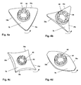
- FIG. 4a the cleaning element 76 is off FIG. 2 shown in perspective.
- the outer shape of the cleaning element 76 is formed as a triangle.
- the cleaning element 76 seen in the direction of rotation (indicated by an arrow) has three scraping edges 78a, 78b, 78c.
- the scraping edges 78 are formed in the solder to the plane 88.
- FIGS. 4b and 4c shown star-shaped with three stripping edges 78a, 78b, 78c and four stripping edges 78a, 78b, 78c, 78d or as in FIG. 4d shown oval with two scraping edges 78a, 78b with respect to the direction of rotation of the approach form.
Landscapes
- Engineering & Computer Science (AREA)
- Mechanical Engineering (AREA)
- Textile Engineering (AREA)
- Spinning Or Twisting Of Yarns (AREA)
- Preliminary Treatment Of Fibers (AREA)
Abstract
Description
- Die Erfindung bezieht sich auf eine Reinigungsvorrichtung für eine Verdichtungsvorrichtung mit einem Antriebselement und einem um eine Drehachse drehbar gelagertes Faserverarbeitungselement mit einem Ansatz, wobei der Ansatz mit dem Antriebselement zusammenwirkt und eine Getriebestufe ausbildet, die derart ausgelegt ist, dass der Ansatz und das Antriebselement mit einer unterschiedlichen Drehzahl rotieren.
- Aus der
WO 2012068692 A1 ist eine Vorrichtung zum Verdichten eines Faserbandes an einer Spinnmaschine mit einem mit Saugluft beaufschlagten, angetriebenen und umlaufenden Verdichtungselement mit einem Ansatz bekannt, welches mit einem Antriebselement zusammenwirkt, das in einer Betriebsstellung mit einem angetriebenen Element der Spinnmaschine unter Bildung einer Getriebestufe eine Antriebsverbindung bildet. - Nachteilig an der Vorrichtung gemäss der
WO 2012068692 A1 ist, dass sich während des Verdichtungsvorgangs einzelne Fasern vom zu verdichtenden Fasergut lösen und sich am Umfang des Verdichtungselementes ablagern. Diese Fasern können sich in Richtung der äusseren Stirnseite des Verdichtungselementes bis an das Antriebselement fortbewegen. Die Bewegung der Fasern kann z.B durch die Rotation des Verdichtungselementes erzeugt werden oder durch die bei der Rotation des Verdichtungselementes entstehende Luftströmung. Hierbei besteht die Gefahr, dass Fasern, die an die äussere Stirnseite des Antriebselementes gelangen, sich bis an den Aussenumfang des Ansatzes fortbewegen und sich an diesem festsetzen. - Dies hat zur Folge, dass die Innenfläche des Antriebselementes nicht mehr in direktem Kontakt mit dem Aussenumfang des Ansatzes steht, wodurch eine kontinuierliche Übertragung des Antriebsmoments vom Antriebselement auf das Verdichtungselement nicht mehr gewährleistet ist. Als Folge ändert sich das Geschwindigkeitsverhältnis zwischen dem Verdichtungselement und der unteren Ausgangswalze des Streckwerks, was sich negativ auf die Qualität der Verdichtung des Fasergutes auswirkt.
- Es besteht daher die Notwendigkeit, das Antriebselement nach einer bestimmten Laufzeit der Verdichtungsvorrichtung von dem Verdichtungselement zu entfernen und die äussere Stirnseite des Antriebselementes bzw. den Aussenumfang des Ansatzes von den angesammelten Fasern zu befreien. Dies ist mit einem hohen Wartungsaufwand und hohen Stillstandzeiten der Spinnmaschine verbunden.
- Der Erfindung liegt somit die Aufgabe zugrunde, eine Verdichtungsvorrichtung zum Verdichten eines Fasergutes an einer Spinnmaschine derart auszubilden, dass Fasern, die sich während des Verdichtungsvorgangs vom zu verdichtenden Fasergut ablösen, nicht im Bereich der äusseren Stirnseite des Antriebselementes ablagern.
- Zur Lösung der Aufgabe wird nunmehr vorgeschlagen eine Reinigungsvorrichtung für die Verdichtungsvorrichtung vorzusehen, wobei die Reinigungsvorrichtung ein Reinigungselement umfasst, welches in Richtung der Drehachse auf einer dem Faserverarbeitungselement abgewandten Stirnseite des Antriebselementes angeordnet ist und mit dem Ansatz drehfest verbunden ist, wobei das Reinigungselement wenigstens eine Abstreifkante aufweist, welche in einer Ebene parallel zur Stirnseite des Antriebselements verläuft und in ihrem Verlauf einen zunehmenden Abstand zur Drehachse aufweist. Die Abstreifkante des Reinigungselementes hat die vorteilhafte funktionale Wirkung, dass jene Fasern, die an die äussere Stirnseite des Antriebselementes gelangen unmittelbar von der Abstreifkante des Reinigungselementes abgestreift werden, so dass sich diese Fasern nicht mehr bis an den Aussenumfang des Ansatzes fortbewegen und sich an diesem festsetzen können. Folglich kann die Verdichtungsvorrichtung kontinuierlich betrieben werden und es muss daher kein Wartungsaufwand und es müssen auch keine hohen Stillstandzeiten der Spinnmaschine berücksichtigt werden. Entsprechend kann für die bekannte Verdichtungsvorrichtung mit der erfindungsgemässen Reinigungsvorrichtung mit Abstreifkante eine höhere Produktivität beim Verdichten des Fasergutes erzielt werden.
- Im Rahmen der vorliegenden Anmeldung ist als Abstreifkante jene Kante am Reinigungselement gemeint, die in Drehrichtung des Reinigungselementes gesehen das Fasergut aktiv weg fördert. Alle anderen Kanten am Reinigungselement, die bezüglich der Drehrichtung keine Wegförderfunktion haben, werden nicht als Abstreifkante angesehen. Selbstverständlich ist bei Umkehr der Drehrichtung des Faserverarbeitungselements die entsprechend zugeordnete achsensymmetrische andere Kante mit Wegförderfunktion als Abstreifkante zu verstehen.
- Vorzugsweise überragt die Abstreifkante zumindest abschnittsweise den Ansatz in radialer Richtung zur Drehachse. Dies hat den vorteilhaften Effekt, dass in Drehrichtung des Reinigungselementes gesehen die Abstreifkante optimal die Fasern auf der Stirnseite des Antriebselementes abstreifen.
- Bevorzugt ist die drehfeste Verbindung des Reinigungselementes mit dem Ansatz eine Schnappverbindung. Die Schnappverbindung hat den Vorteil, dass für einen Austausch des Reinigungselementes - bei Defekt - kein Werkzeug notwendig ist, da der Austausch vielmehr manuell erfolgen kann. Somit ist der Austausch durch die Schnappverbindung schnell und unkompliziert.
- Alternativ könnte die drehfeste Verbindung des Reinigungselementes mit dem Ansatz eine Schraub-, Niet- oder Klebeverbindung sein. Diese Verbindungstechniken sind zwar denkbar, aber beim Anbringen ebenso wie beim Austauschen eher unpraktisch.
- Vorzugsweise weist das Reinigungselement mehrere Abstreifkanten auf, welche sternförmig angeordnet sind. Die Mehrzahl von sternförmig angeordneten Abstreifkanten hat den Vorteil, dass in Drehrichtung des Reinigungselementes gesehen die Abstreifkanten optimal die Fasern auf der Stirnseite des Antriebselementes abstreifen. Die sternförmige Anordnung erlaubt zudem eine flächendeckende Reinigung der Fasern auf der Stirnseite des Antriebselementes. Auf diese Art und Weise wird eine Ansammlung der Fasern auf dem Aussenumfang des Ansatzes zumindest annährend vollständig unterbunden.
- Vorzugsweise weist das Reinigungselement drei Abstreifkanten auf. Bei dieser Ausführung ist das Reinigungselement vorzugsweise als gleichseitiges Dreieck ausgebildet, so dass die drei Abstreifkanten in Drehrichtung gesehen die Fasern auf der Stirnseite des Antriebselementes um 120° versetzt zueinander abstreifen.
- Weiter bevorzugt weist das Reinigungselement vier Abstreifkanten auf. Bei dieser Ausführung ist das Reinigungselement vorzugsweise als Raute ausgebildet, so dass die vier Abstreifkanten in Drehrichtung gesehen die Fasern auf der Stirnseite des Antriebselementes um 90° versetzt zueinander abstreifen.
- Bevorzugt ist die Abstreifkante konkav ausgebildet. Dies hat den vorteilhaften Effekt, dass die Fasern in Drehrichtung des Reinigungselementes gesehen vor der Abstreifkante her transportiert werden. Auf diese Art und Weise ist ein optimaler Abtransport der Fasern entlang der konkav ausgebildeten Abstreifkante möglich.
- Weitere Vorteile der Erfindung sind anhand eines nachfolgend beschriebenen und gezeigten Ausführungsbeispiels zu entnehmen.
- Es zeigen:
- Fig.1
- eine schematische Seitenansicht einer Spinnstelle einer Ringspinnmaschine mit einer Streckwerkseinheit und einer anschliessenden Verdichtungsvorrichtung;
- Fig. 2
- eine vergrösserte Teilansicht X nach
Fig. 1 mit einer drehbar gelagerten Saugtrommel einer an einem Träger befestigten Verdichtungsvorrichtung und Antriebselement; - Fig. 3
- eine vergrösserte Seitenansicht Y nach
Fig. 2 einer Antriebsvorrichtung mit einem Reibrad; - Fig. 4a-d
- vier schematische Ausführungsbeispiele jeweils in perspektivischer Darstellung von erfindungsgemässen Reinigungselementen.
-
Figur 1 zeigt eine schematische Seitenansicht einer Spinnstelle 10 einer Spinnmaschine (Ringspinnmaschine) mit einer Streckwerkseinheit 12, welche mit einem Eingangswalzenpaar 14, 16, einem Mittelwalzenpaar 18, 20 und einem Ausgangswalzenpaar 22, 24 versehen ist. Die unteren Walzenpaare 14, 18, 22 sind, wie schematisch angedeutet, mit einem Antrieb A verbunden. Die oberen Walzenpaare 16, 20, 24 sind als Druckwalzen ausgeführt und an einem schwenkbar gelagerten Druckarm 19 drehbeweglich gelagert. Der Druckarm 19 ist um eine Achse 21 schwenkbar gelagert und wird über ein Federelement F beaufschlagt. Über die angetriebenen Unterwalzen 14, 18, 22 werden die Druckwalzen 16, 20, 24, bzw. ein Riemchen 27 über ein Riemchen 25 über Friktion angetrieben. Die Umfangsgeschwindigkeit der angetriebenen Walze 18 ist etwas höher als die Umfangsgeschwindigkeit der angetriebenen Walze 14. - Ein der Streckwerkseinheit 12 zugeführtes Fasergut wird in Form einer Lunte L zwischen dem Eingangswalzenpaar 14, 16 und dem Mittelwalzenpaar 18, 20 einem Vorverzug unterworfen. Der Hauptverzug des Fasergutes L entsteht zwischen dem Mittelwalzenpaar 18, 20 und dem Ausgangswalzenpaar 22, 24, wobei die Ausgangswalze 22 eine wesentlich höhere Umdrehungsgeschwindigkeit als die Mittelwalze 18 aufweist. Das von dem Ausgangswalzenpaar 22, 24 abgegebene verstreckte Fasergut V wird nach unten abgelenkt und gelangt in den Bereich einer Saugzone SZ einer nachfolgenden Faserverarbeitungsvorrichtung in Form einer Saugtrommel 26 als Teil einer Verdichtungsvorrichtung VM.
- Die Saugtrommel 26 ist im Bereich ihres äusseren Endes auf einer eine Drehachse 34 aufweisenden Welle 28 drehbar gelagert. Die Welle 28 ist in einer Aufnahme 29 eines Trägers 32 befestigt. Die Welle 28 weist im Bereich der Aufnahme 29 einen etwas grösseren Durchmesser auf, während die, von dieser Aufnahme 29 nach beiden Seiten sich erstreckenden Enden der Welle 28 einen verjüngten Durchmesser aufweisen und zur Aufnahme von Lagern dienen. Die drehbare Lagerung der Saugtrommel 26 wird weiter unten im Zusammenhang mit
Figur 3 im Detail erläutert. - Der Träger 32 ist an seinem der Spinnmaschine zugekehrten Ende mit einem U-förmigen, bzw. gabelförmigem Endstück 38 versehen, welches mit seiner Innenfläche auf einem Teilbereich des Aussenumfanges eines Saugrohres 40 aufliegt.
- Das Saugrohr 40 ist über ein oder mehrere Verbindungskanäle 42 mit einem zentralen Hauptkanal 44 verbunden. Dieser Hauptkanal 44 steht mit einer Unterdruckquelle SP in Verbindung, welche über eine Steuereinheit ST angesteuert werden kann.
- Im Anschluss an die Saugzone SZ ist für die Saugtrommel 26 eine Klemmwalze 46 vorgesehen, die über eine Druckbelastung auf der Saugtrommel 26 aufliegt und mit dieser eine Klemmlinie P bildet. Dabei ist die Klemmwalze 46 auf einer Achse 48 drehbar gelagert, welche an einem Lagerelement 50 befestigt ist, das über Schrauben 52 (oder sonstige Befestigungselemente) mit einem Federelement 54 verbunden ist. Das Federelement 54 ist über schematisch dargestellte Schrauben 52 (oder sonstige Befestigungselemente) am Träger 32 befestigt.
- Die Klemmlinie P bildet gleichzeitig einen so genannten "Drehsperrungsspalt", von welchem das Fasergut in der Förderrichtung FS in Form eines komprimierten Garnes FK unter Drehungserteilung einer schematisch gezeigten Ringspinneinrichtung zugeführt wird. Diese ist mit einem Ring 56 und einem Läufer 58 versehen, wobei das Garn auf eine Hülse 60 zur Bildung einer Spule 62 (Kops) aufgewickelt wird. Zwischen der Klemmlinie P und dem Läufer 58 ist ein Fadenführer 64 angeordnet. Der Ring 56 ist an einem Ringrahmen 66 befestigt, welcher während dem Spinnprozess eine Auf- und Abbewegung durchführt.
- In der in
Figur 2 gezeigten Lage befindet sich die Saugtrommel 26 in einer Arbeitsposition, in welcher der Aussenumfang U eines Antriebselementes in Form eines Reibrades 70 über eine entsprechend aufgebrachte Druckbelastung auf dem Aussenumfang U7 der angetriebenen Ausgangswalze 22 aufliegt. Auf diese Weise wird das Reibrad 70 über Friktion von der Ausgangswalze 22 in einer ersten Getriebestufe G1 angetrieben. - Ebenfalls über Friktion überträgt das Reibrad 70 den Antrieb in einer zweiten Getriebestufe G2 auf einen ringförmigen Ansatz 72 der Saugtrommel 26. Dies erfolgt an der Stelle, wo sich die Innenfläche IF mit dem Innendurchmesser D2 des Reibrades 70 und der Aussenumfang AU des Ansatzes 72 mit dem Aussendurchmesser D1 berühren bzw. aufeinander liegen. Die Drehachse des Reibrades 70 ist achsenparallel versetzt zur Drehachse 34 des Ansatzes 72, so dass hinsichtlich der zweiten Getriebestufe G2 das von der Ausgangswalze 22 angetriebene Reibrad 70 mit einer unterschiedlichen Drehzahl wie die Saugtrommel 26 rotiert.
- In nachteilhafter Weise ist beim bekannten Stand der Technik eine kreisförmige Abdeckkappe in Richtung der Drehachse 34 auf einer der Saugtrommel 26 abgewandten Stirnseite 82 des Reibrades 70 angeordnet und mit dem Ansatz 72 drehfest verbunden.
- Entsprechend können sich während des Verdichtungsvorgangs einzelne Fasern vom zu verdichtenden Fasergut V lösen, am Umfang der Saugtrommel 26 ablagern und sich in Richtung der Stirnseite 82 des Reibrades 70 fortbewegen und so in den axialen Spalt zwischen der Stirnseite 82 des Reibrades 70 und der kreisförmigen Abdeckkappe gelangen. Die Bewegung der Fasern kann z.B. durch die Rotation der Saugtrommel 26 oder die bei der Rotation der Saugtrommel 26 entstehende Luftströmung erzeugt werden. Hierbei besteht die Gefahr, dass Fasern, die in den axialen Spalt gelangen, sich bis an den Aussenumfang AU des Ansatzes 72 fortbewegen und an diesem festsetzen. Dies hat zur Folge, dass die Innenfläche IF des Reibrades 70 nicht mehr in direktem Kontakt mit dem Aussenumfang AU des Ansatzes 72 steht, wodurch eine kontinuierliche Übertragung des Antriebsmoments vom Reibrad 70 auf die Saugtrommel 26 nicht mehr gewährleistet ist. Als Folge ändert sich das Geschwindigkeitsverhältnis zwischen der Saugtrommel 26 und der unteren Ausgangswalze 22 des Streckwerks 2. Hierdurch wird das zu verdichtende Fasergut V in der Saugzone SZ gestaucht, was sich negativ auf die Qualität der Verdichtung des Fasergutes V auswirkt. Es besteht daher die Notwendigkeit, das Reibrad 70 nach einer bestimmten Laufzeit der Verdichtungsvorrichtung VM von der Saugtrommel 26 zu entfernen und den Aussenumfang AU des Ansatzes 72 von den angesammelten Fasern zu befreien. Dies ist mit einem hohen Wartungsaufwand und hohen Stillstandzeiten der Spinnmaschine verbunden.
- Um diesen Nachteilen aus dem Stand der Technik entgegenzuwirken kommt wie in Figur 2 rein schematisch und gestrichelt gezeigt ein erfindungsgemässes Reinigungselement 76 anstatt der kreisförmigen Abdeckkappe zum Einsatz. Entsprechend ist das erfindungsgemässe Reinigungselement 76 in Richtung der Drehachse 34 auf der der Siebtrommel 26 abgewandten Stirnseite 82 des Reibrades 70 angeordnet und mit dem Ansatz 72 drehfest verbunden. Folglich dreht sich das Reinigungselement 76 mit der gleichen Drehzahl wie die Saugtrommel 26 und unterschiedlich zum Reibrad 70, wobei alle Elemente 70, 72, 76 in gleicher Drehrichtung angetrieben sind.
- Bevorzugt ist das Reinigungselement 76 aus Polyamid vom Typ PA12 gefertigt und weist opake Eigenschaften auf. Dies bedeutet, dass das Reinigungselement vorzugsweise transparent, transluzent bzw. klarsichtig ausgebildet ist. Somit kann durch das Reinigungselement 76 hindurch direkt auf die Stirnseite 82 des Reibrades 70 und den Ansatz 72 gesehen werden.
- Das Reinigungselement 76 weist bezüglich der Drehrichtung des Ansatzes 72 eine Abstreifkante 78 auf. Die Abstreifkante 78 verläuft, wie in
Figur 3 gezeigt, in einer Ebene (gestrichelt dargestellt) parallel zur Stirnseite 82 des Reibrades 70 und weist in ihrem Verlauf einen zunehmenden Abstand zur Drehachse 34 der Welle 28 auf. Die Abstreifkante 78 folgt in Drehrichtung gesehen der Umlaufbahn des Ansatzes 72 und kann dabei wegen der unterschiedlichen Drehzahl zwischen Reibrad 70 und Ansatz 72 sich ansammelnde Fasern auf der Stirnseite 82 des Reibrades 70 unmittelbar weg fördern bzw. abstreifen. In Drehrichtung des Reinigungselementes 76 gesehen dienen nur jene Kanten des Reinigungselementes 76 als Abstreifkanten 78, welche in Drehrichtung mitlaufen, da nur diese die Fasern weg fördern bzw. abstreifen können. Für den Fall, dass sich die Drehrichtung des Reibrades 70 und der Saugtrommel 26 umkehrt, würde im logischen Umkehrschluss die spiegelsymmetrische Kante als Abstreifkante 78' (inFigur 2 mit Strichpunkten gekennzeichnet) dienen. - Auf die erfindungsgemässe Art und Weise wird nun verhindert, dass sich Fasern von der Stirnseite 82 des Reibrades 70 in Richtung des Aussenumfangs AU des Ansatzes 72 fortbewegen können, wie dies in nachteilhafter Weise beim bekannten Stand der Technik der Fall ist.
- In
Figur 3 ist gezeigt, dass die Saugtrommel 26 im Bereich ihres äusseren Endes über Lager K auf der Welle 28 drehbar gelagert ist. Zur axialen Fixierung der Saugtrommel 26 auf der Welle 28 ist auf der Welle 28 ein Sicherungsring 74 angebracht, der das axiale Verschieben der Saugtrommel 26 während des Betriebes unterbindet. - Zur Befestigung des Reinigungselementes 76 am ringförmigen Ansatz 72 der Saugtrommel 26 weist das Reinigungselement 76 auf der dem Ansatz 72 zugewandten Seite kronenförmig angeformte Federfinger 80 auf (siehe diesbezüglich
Figuren 4a bis 4d ). Die Federfinger 80 des Reinigungselementes 76 ragen in die lichte Weite des ringförmigen Ansatzes 72 der Saugtrommel 26 hinein. Die Aussenabmessung des ringförmigen Ansatzes 72 ist dabei so gewählt, dass er in der inFigur 3 gezeigten Lage eine Klemmwirkung innerhalb der lichten Weite des Ansatzes 72 ausübt. - Wie schematisch dargestellt, können die Federfinger 80 mit zusätzlichen nach radial aussen ragenden Rastnasen 84 versehen sein, welche zur Fixierung des Reinigungselementes 76 in umlaufende Vertiefungen 86 innerhalb der lichten Weite des Ansatzes 72 eingreifen. Durch das Reinigungselement 76 wird das Reibrad 70 in axialer Richtung auf der Welle 28 in seiner Position gehalten.
- In
Figur 4a ist das Reinigungselement 76 ausFigur 2 in perspektivischer Darstellung gezeigt. Hierbei sind klar und deutlich die Federfinger 80 mit Rastnasen 84 für die Befestigung des Reinigungselementes 76 in der lichten Weite des Ansatzes 72 als Schnappverbindung gezeigt. Bei diesem Ausführungsbeispiel ist die äussere Form des Reinigungselementes 76 als Dreieck ausgebildet. Entsprechend weist das Reinigungselement 76 in Drehrichtung (mit einem Pfeil angedeutet) gesehen drei Abstreifkanten 78a, 78b, 78c auf. In vorliegendem Ausführungsbeispiel sind die Abstreifkanten 78 im Lot zur Ebene 88 ausgebildet. Alternativ ist es auch denkbar, die Abstreifkanten 78 konkav auszubilden. - Hinsichtlich des Reinigungselementes 76 ist es auch denkbar, wie in
Figur 4b und 4c gezeigt, dieses sternförmig mit drei Abstreifkanten 78a, 78b, 78c bzw. vier Abstreifkanten 78a, 78b, 78c, 78d oder wie inFigur 4d gezeigt oval mit zwei Abstreifkanten 78a, 78b bezüglich der Drehrichtung des Ansatzes auszubilden. - Es sind jedoch auch andere Ausführungsformen eines Reinigungselementes 76 möglich, die in dieser Anmeldung nicht explizit ausgeführt sind, aber für den Fachmann offensichtlich sind, um den gewünschten Reinigungseffekt auf der Stirnseite des Reibrades zu erhalten.
Claims (8)
- Reinigungsvorrichtung für eine Verdichtungsvorrichtung mit einem Antriebselement (70) und einem um eine Drehachse drehbar gelagertes Faserverarbeitungselement (26) mit einem Ansatz (72), wobei der Ansatz (72) mit dem Antriebselement (70) zusammenwirkt und eine Getriebestufe (G2) ausbildet, die derart ausgelegt ist, dass das Faserverarbeitungselement (26) und das Antriebselement (70) mit einer unterschiedlichen Drehzahl rotieren, dadurch gekennzeichnet, dass die Reinigungsvorrichtung ein Reinigungselement (76) umfasst, welches in Richtung der Drehachse auf einer dem Faserverarbeitungselement (26) abgewandten Stirnseite (82) des Antriebselementes (70) angeordnet ist und mit dem Ansatz (72) drehfest verbunden ist, wobei das Reinigungselement (76) wenigstens eine Abstreifkante (78) aufweist, welche in einer Ebene (88) parallel zur Stirnseite (82) des Antriebselements (70) verläuft und in ihrem Verlauf einen zunehmenden Abstand zur Drehachse aufweist.
- Reinigungsvorrichtung nach Anspruch 1, dadurch gekennzeichnet, dass die Abstreifkante (78) zumindest abschnittsweise den Ansatz (72) in radialer Richtung zur Drehachse überragt.
- Reinigungsvorrichtung nach Anspruch 1 oder 2, dadurch gekennzeichnet, dass die drehfeste Verbindung des Reinigungselementes (76) mit dem Ansatz (72) eine Schnappverbindung ist.
- Reinigungsvorrichtung nach einem der Ansprüche 1 bis 3, dadurch gekennzeichnet, dass das Reinigungselement (76) mehrere Abstreifkanten (78) aufweist, welche sternförmig angeordnet sind.
- Reinigungsvorrichtung nach einem der Ansprüche 1 bis 4, dadurch gekennzeichnet, dass das Reinigungselement (76) drei Abstreifkanten (78a, 78b, 78c) aufweist.
- Reinigungsvorrichtung nach einem der Ansprüche 1 bis 4, dadurch gekennzeichnet, dass das Reinigungselement (76) vier Abstreifkanten (78a, 78b, 78c, 78d) aufweist.
- Reinigungsvorrichtung nach Anspruch 1, dadurch gekennzeichnet, dass die Abstreifkante (78) konvex ausgebildet ist.
- Spinnmaschine mit einer Vielzahl von Verdichtungsvorrichtungen, dadurch gekennzeichnet, dass zumindest eine Verdichtungsvorrichtung eine Reinigungsvorrichtung nach einem der Ansprüche 1 bis 7 aufweist.
Applications Claiming Priority (1)
| Application Number | Priority Date | Filing Date | Title |
|---|---|---|---|
| CH01353/15A CH711549A1 (de) | 2015-09-18 | 2015-09-18 | Reinigungsvorrichtung für eine Verdichtungsvorrichtung. |
Publications (2)
| Publication Number | Publication Date |
|---|---|
| EP3144420A1 true EP3144420A1 (de) | 2017-03-22 |
| EP3144420B1 EP3144420B1 (de) | 2020-04-22 |
Family
ID=56801468
Family Applications (1)
| Application Number | Title | Priority Date | Filing Date |
|---|---|---|---|
| EP16185820.4A Active EP3144420B1 (de) | 2015-09-18 | 2016-08-26 | Verdichtungsvorrichtung mit einer reinigungsvorrichtung |
Country Status (3)
| Country | Link |
|---|---|
| EP (1) | EP3144420B1 (de) |
| CN (1) | CN106544764B (de) |
| CH (1) | CH711549A1 (de) |
Families Citing this family (1)
| Publication number | Priority date | Publication date | Assignee | Title |
|---|---|---|---|---|
| CN107861271A (zh) * | 2017-09-19 | 2018-03-30 | 合肥惠科金扬科技有限公司 | 一种用于清除tft‑lcd液晶屏表面灰尘的手动擦拭器 |
Citations (5)
| Publication number | Priority date | Publication date | Assignee | Title |
|---|---|---|---|---|
| DE812036C (de) * | 1950-01-04 | 1951-08-27 | Erich Dipl-Ing Golde | Verschluss fuer Flaschen und aehnliche Behaelter mit Innengewinde |
| FR1040076A (fr) * | 1951-07-24 | 1953-10-13 | Bognier & Burnet Ets | Perfectionnements aux bouchons en caoutchouc |
| WO2012068692A1 (de) | 2010-11-26 | 2012-05-31 | Maschinenfabrik Rieter Ag | Antriebsvorrichtung für eine verdichtungsvorrichtung an einer spinnmaschine |
| US20130032497A1 (en) * | 2011-08-02 | 2013-02-07 | Pickard Jr George L | Shipping and Installation Container For Soft Tubing |
| WO2015128713A1 (de) * | 2014-02-27 | 2015-09-03 | Maschinenfabrik Rieter Ag | Verdichtungsvorrichtung mit saugtrommel |
Family Cites Families (7)
| Publication number | Priority date | Publication date | Assignee | Title |
|---|---|---|---|---|
| GB191007385A (en) * | 1910-03-24 | 1911-01-12 | Ernest Knowles | Improvements in connection with Roller Cleaners for the Drawing Rollers Employed in Various Textile Machines. |
| US2228809A (en) * | 1937-07-06 | 1941-01-14 | Solanas Ramon Balmes | Mechanism for drawing textile rovings provided with needle rollers |
| US3733644A (en) * | 1971-07-16 | 1973-05-22 | Deering Milliken Res Corp | Scraper member for drafting system |
| DE3320208A1 (de) * | 1983-06-03 | 1984-12-06 | Ernst Jacobi & Co Kg, 8900 Augsburg | Vorrichtung zum abscheiden des bei textilmaschinen anfallenden faserflugs |
| DE10019636A1 (de) * | 2000-04-19 | 2001-10-25 | Temco Textilmaschkomponent | Andruckrolle |
| DE502005004205D1 (de) * | 2004-07-07 | 2008-07-03 | Rieter Ag Maschf | Putzeinrichtung einer textilmaschine |
| CH708518A1 (de) * | 2013-09-13 | 2015-03-13 | Rieter Ag Maschf | Saugtrommel einer Vorrichtung zum Verdichten eines Fasergutes mit einer Dichtung. |
-
2015
- 2015-09-18 CH CH01353/15A patent/CH711549A1/de not_active Application Discontinuation
-
2016
- 2016-08-26 EP EP16185820.4A patent/EP3144420B1/de active Active
- 2016-09-14 CN CN201610823324.4A patent/CN106544764B/zh active Active
Patent Citations (5)
| Publication number | Priority date | Publication date | Assignee | Title |
|---|---|---|---|---|
| DE812036C (de) * | 1950-01-04 | 1951-08-27 | Erich Dipl-Ing Golde | Verschluss fuer Flaschen und aehnliche Behaelter mit Innengewinde |
| FR1040076A (fr) * | 1951-07-24 | 1953-10-13 | Bognier & Burnet Ets | Perfectionnements aux bouchons en caoutchouc |
| WO2012068692A1 (de) | 2010-11-26 | 2012-05-31 | Maschinenfabrik Rieter Ag | Antriebsvorrichtung für eine verdichtungsvorrichtung an einer spinnmaschine |
| US20130032497A1 (en) * | 2011-08-02 | 2013-02-07 | Pickard Jr George L | Shipping and Installation Container For Soft Tubing |
| WO2015128713A1 (de) * | 2014-02-27 | 2015-09-03 | Maschinenfabrik Rieter Ag | Verdichtungsvorrichtung mit saugtrommel |
Also Published As
| Publication number | Publication date |
|---|---|
| CH711549A1 (de) | 2017-03-31 |
| CN106544764B (zh) | 2020-12-08 |
| CN106544764A (zh) | 2017-03-29 |
| EP3144420B1 (de) | 2020-04-22 |
Similar Documents
| Publication | Publication Date | Title |
|---|---|---|
| EP2643507B1 (de) | Spinnmaschine mit verdichtungseinrichtung | |
| EP3044355B1 (de) | Saugtrommel mit dichtung | |
| EP2643506B1 (de) | Antriebsvorrichtung für eine verdichtungsvorrichtung an einer spinnmaschine | |
| EP3140441B1 (de) | Vorrichtung mit einem streckwerk zum reinigen von walzenoberflächen einer streckwerksvorrichtung | |
| EP3110992B1 (de) | Verdichtungsvorrichtung mit saugtrommel | |
| EP0350797B1 (de) | Streckwerk für Spinnmaschinen | |
| DE2648066C2 (de) | Offenend-Spinnmaschine mit einer verfahrbaren Wartungsvorrichtung | |
| EP2503035B1 (de) | Streckwerk mit Verdichtungseinrichtung an einer Spinnmaschine | |
| EP3144420B1 (de) | Verdichtungsvorrichtung mit einer reinigungsvorrichtung | |
| CH706775A2 (de) | Vorrichtung an einer Spinnereimaschine, insbesondere Karde, Strecke, Kämmmaschine, Bandwickler o. dgl., mit einem Streckwerk. | |
| DE19903113A1 (de) | Vorrichtung zum Verdichten eines verstreckten Faserverbandes | |
| EP1066420B1 (de) | Maschine zur oberflächenbearbeitung mindestens einer textilen warenbahn, insbesondere zum rauhen und/oder schmirgeln oder dergleichen | |
| DE4031769A1 (de) | Streckwerk mit wenigstens einem reinigungsband | |
| DE2458241A1 (de) | Verfahren und vorrichtung zum kardieren von vliesstoffen | |
| CH680594A5 (en) | Bearings for roller - has tubular cover over the journals and bearings extending into gap in the roller to exclude dust and fly | |
| DE3834039A1 (de) | Querbandanordnung am ausgang einer karde | |
| DE2436513A1 (de) | Karde zum behandeln von fasern | |
| DE3436526A1 (de) | Bandtrichter fuer die ablieferung einer spinnereivorbereitungsmaschine | |
| EP2791401B1 (de) | Kämmmaschine nach dem heilmann prinzip | |
| DE102010032341A1 (de) | Streckwerk für einen Stapelfaserverband und Druckwalzenaggregat dafür | |
| DE1266190B (de) | Vorrichtung zum mechanisch- pneumatischen Reinigen von Ober- und Unterwalzen an Streckwerken von Spinnereimaschinen | |
| CH709798A1 (de) | Putzvorrichtung zum Reinigen von Saugtrommeloberflächen einer Verdichtungsvorrichtung für Spinnmaschinen, sowie die Verdichtungsvorrichtung, sowie die Ringspinnmaschine. | |
| DE19940817A1 (de) | Spinnmaschine mit Verdichtungseinrichtung | |
| DE102007013109A1 (de) | Vorrichtung zur Verarbeitung von Fasermaterial | |
| WO2024083541A1 (de) | Kammbürstensegment und entsprechende rundkammbürste |
Legal Events
| Date | Code | Title | Description |
|---|---|---|---|
| PUAI | Public reference made under article 153(3) epc to a published international application that has entered the european phase |
Free format text: ORIGINAL CODE: 0009012 |
|
| STAA | Information on the status of an ep patent application or granted ep patent |
Free format text: STATUS: THE APPLICATION HAS BEEN PUBLISHED |
|
| AK | Designated contracting states |
Kind code of ref document: A1 Designated state(s): AL AT BE BG CH CY CZ DE DK EE ES FI FR GB GR HR HU IE IS IT LI LT LU LV MC MK MT NL NO PL PT RO RS SE SI SK SM TR |
|
| AX | Request for extension of the european patent |
Extension state: BA ME |
|
| STAA | Information on the status of an ep patent application or granted ep patent |
Free format text: STATUS: REQUEST FOR EXAMINATION WAS MADE |
|
| 17P | Request for examination filed |
Effective date: 20170914 |
|
| RBV | Designated contracting states (corrected) |
Designated state(s): AL AT BE BG CH CY CZ DE DK EE ES FI FR GB GR HR HU IE IS IT LI LT LU LV MC MK MT NL NO PL PT RO RS SE SI SK SM TR |
|
| STAA | Information on the status of an ep patent application or granted ep patent |
Free format text: STATUS: EXAMINATION IS IN PROGRESS |
|
| 17Q | First examination report despatched |
Effective date: 20190528 |
|
| GRAP | Despatch of communication of intention to grant a patent |
Free format text: ORIGINAL CODE: EPIDOSNIGR1 |
|
| STAA | Information on the status of an ep patent application or granted ep patent |
Free format text: STATUS: GRANT OF PATENT IS INTENDED |
|
| INTG | Intention to grant announced |
Effective date: 20191209 |
|
| GRAS | Grant fee paid |
Free format text: ORIGINAL CODE: EPIDOSNIGR3 |
|
| GRAA | (expected) grant |
Free format text: ORIGINAL CODE: 0009210 |
|
| STAA | Information on the status of an ep patent application or granted ep patent |
Free format text: STATUS: THE PATENT HAS BEEN GRANTED |
|
| AK | Designated contracting states |
Kind code of ref document: B1 Designated state(s): AL AT BE BG CH CY CZ DE DK EE ES FI FR GB GR HR HU IE IS IT LI LT LU LV MC MK MT NL NO PL PT RO RS SE SI SK SM TR |
|
| REG | Reference to a national code |
Ref country code: CH Ref legal event code: EP |
|
| REG | Reference to a national code |
Ref country code: DE Ref legal event code: R096 Ref document number: 502016009623 Country of ref document: DE |
|
| REG | Reference to a national code |
Ref country code: IE Ref legal event code: FG4D Free format text: LANGUAGE OF EP DOCUMENT: GERMAN |
|
| REG | Reference to a national code |
Ref country code: AT Ref legal event code: REF Ref document number: 1260178 Country of ref document: AT Kind code of ref document: T Effective date: 20200515 |
|
| REG | Reference to a national code |
Ref country code: LT Ref legal event code: MG4D |
|
| REG | Reference to a national code |
Ref country code: NL Ref legal event code: MP Effective date: 20200422 |
|
| PG25 | Lapsed in a contracting state [announced via postgrant information from national office to epo] |
Ref country code: IS Free format text: LAPSE BECAUSE OF FAILURE TO SUBMIT A TRANSLATION OF THE DESCRIPTION OR TO PAY THE FEE WITHIN THE PRESCRIBED TIME-LIMIT Effective date: 20200822 Ref country code: SE Free format text: LAPSE BECAUSE OF FAILURE TO SUBMIT A TRANSLATION OF THE DESCRIPTION OR TO PAY THE FEE WITHIN THE PRESCRIBED TIME-LIMIT Effective date: 20200422 Ref country code: NO Free format text: LAPSE BECAUSE OF FAILURE TO SUBMIT A TRANSLATION OF THE DESCRIPTION OR TO PAY THE FEE WITHIN THE PRESCRIBED TIME-LIMIT Effective date: 20200722 Ref country code: GR Free format text: LAPSE BECAUSE OF FAILURE TO SUBMIT A TRANSLATION OF THE DESCRIPTION OR TO PAY THE FEE WITHIN THE PRESCRIBED TIME-LIMIT Effective date: 20200723 Ref country code: PT Free format text: LAPSE BECAUSE OF FAILURE TO SUBMIT A TRANSLATION OF THE DESCRIPTION OR TO PAY THE FEE WITHIN THE PRESCRIBED TIME-LIMIT Effective date: 20200824 Ref country code: FI Free format text: LAPSE BECAUSE OF FAILURE TO SUBMIT A TRANSLATION OF THE DESCRIPTION OR TO PAY THE FEE WITHIN THE PRESCRIBED TIME-LIMIT Effective date: 20200422 Ref country code: LT Free format text: LAPSE BECAUSE OF FAILURE TO SUBMIT A TRANSLATION OF THE DESCRIPTION OR TO PAY THE FEE WITHIN THE PRESCRIBED TIME-LIMIT Effective date: 20200422 Ref country code: NL Free format text: LAPSE BECAUSE OF FAILURE TO SUBMIT A TRANSLATION OF THE DESCRIPTION OR TO PAY THE FEE WITHIN THE PRESCRIBED TIME-LIMIT Effective date: 20200422 |
|
| PG25 | Lapsed in a contracting state [announced via postgrant information from national office to epo] |
Ref country code: LV Free format text: LAPSE BECAUSE OF FAILURE TO SUBMIT A TRANSLATION OF THE DESCRIPTION OR TO PAY THE FEE WITHIN THE PRESCRIBED TIME-LIMIT Effective date: 20200422 Ref country code: HR Free format text: LAPSE BECAUSE OF FAILURE TO SUBMIT A TRANSLATION OF THE DESCRIPTION OR TO PAY THE FEE WITHIN THE PRESCRIBED TIME-LIMIT Effective date: 20200422 Ref country code: RS Free format text: LAPSE BECAUSE OF FAILURE TO SUBMIT A TRANSLATION OF THE DESCRIPTION OR TO PAY THE FEE WITHIN THE PRESCRIBED TIME-LIMIT Effective date: 20200422 Ref country code: BG Free format text: LAPSE BECAUSE OF FAILURE TO SUBMIT A TRANSLATION OF THE DESCRIPTION OR TO PAY THE FEE WITHIN THE PRESCRIBED TIME-LIMIT Effective date: 20200722 |
|
| PG25 | Lapsed in a contracting state [announced via postgrant information from national office to epo] |
Ref country code: AL Free format text: LAPSE BECAUSE OF FAILURE TO SUBMIT A TRANSLATION OF THE DESCRIPTION OR TO PAY THE FEE WITHIN THE PRESCRIBED TIME-LIMIT Effective date: 20200422 |
|
| REG | Reference to a national code |
Ref country code: DE Ref legal event code: R097 Ref document number: 502016009623 Country of ref document: DE |
|
| PG25 | Lapsed in a contracting state [announced via postgrant information from national office to epo] |
Ref country code: SM Free format text: LAPSE BECAUSE OF FAILURE TO SUBMIT A TRANSLATION OF THE DESCRIPTION OR TO PAY THE FEE WITHIN THE PRESCRIBED TIME-LIMIT Effective date: 20200422 Ref country code: EE Free format text: LAPSE BECAUSE OF FAILURE TO SUBMIT A TRANSLATION OF THE DESCRIPTION OR TO PAY THE FEE WITHIN THE PRESCRIBED TIME-LIMIT Effective date: 20200422 Ref country code: DK Free format text: LAPSE BECAUSE OF FAILURE TO SUBMIT A TRANSLATION OF THE DESCRIPTION OR TO PAY THE FEE WITHIN THE PRESCRIBED TIME-LIMIT Effective date: 20200422 Ref country code: ES Free format text: LAPSE BECAUSE OF FAILURE TO SUBMIT A TRANSLATION OF THE DESCRIPTION OR TO PAY THE FEE WITHIN THE PRESCRIBED TIME-LIMIT Effective date: 20200422 Ref country code: RO Free format text: LAPSE BECAUSE OF FAILURE TO SUBMIT A TRANSLATION OF THE DESCRIPTION OR TO PAY THE FEE WITHIN THE PRESCRIBED TIME-LIMIT Effective date: 20200422 Ref country code: CZ Free format text: LAPSE BECAUSE OF FAILURE TO SUBMIT A TRANSLATION OF THE DESCRIPTION OR TO PAY THE FEE WITHIN THE PRESCRIBED TIME-LIMIT Effective date: 20200422 |
|
| PG25 | Lapsed in a contracting state [announced via postgrant information from national office to epo] |
Ref country code: PL Free format text: LAPSE BECAUSE OF FAILURE TO SUBMIT A TRANSLATION OF THE DESCRIPTION OR TO PAY THE FEE WITHIN THE PRESCRIBED TIME-LIMIT Effective date: 20200422 Ref country code: SK Free format text: LAPSE BECAUSE OF FAILURE TO SUBMIT A TRANSLATION OF THE DESCRIPTION OR TO PAY THE FEE WITHIN THE PRESCRIBED TIME-LIMIT Effective date: 20200422 |
|
| PLBE | No opposition filed within time limit |
Free format text: ORIGINAL CODE: 0009261 |
|
| STAA | Information on the status of an ep patent application or granted ep patent |
Free format text: STATUS: NO OPPOSITION FILED WITHIN TIME LIMIT |
|
| 26N | No opposition filed |
Effective date: 20210125 |
|
| PG25 | Lapsed in a contracting state [announced via postgrant information from national office to epo] |
Ref country code: MC Free format text: LAPSE BECAUSE OF FAILURE TO SUBMIT A TRANSLATION OF THE DESCRIPTION OR TO PAY THE FEE WITHIN THE PRESCRIBED TIME-LIMIT Effective date: 20200422 |
|
| REG | Reference to a national code |
Ref country code: CH Ref legal event code: PL |
|
| GBPC | Gb: european patent ceased through non-payment of renewal fee |
Effective date: 20200826 |
|
| PG25 | Lapsed in a contracting state [announced via postgrant information from national office to epo] |
Ref country code: CH Free format text: LAPSE BECAUSE OF NON-PAYMENT OF DUE FEES Effective date: 20200831 Ref country code: LU Free format text: LAPSE BECAUSE OF NON-PAYMENT OF DUE FEES Effective date: 20200826 Ref country code: LI Free format text: LAPSE BECAUSE OF NON-PAYMENT OF DUE FEES Effective date: 20200831 |
|
| REG | Reference to a national code |
Ref country code: BE Ref legal event code: MM Effective date: 20200831 |
|
| PG25 | Lapsed in a contracting state [announced via postgrant information from national office to epo] |
Ref country code: SI Free format text: LAPSE BECAUSE OF FAILURE TO SUBMIT A TRANSLATION OF THE DESCRIPTION OR TO PAY THE FEE WITHIN THE PRESCRIBED TIME-LIMIT Effective date: 20200422 |
|
| PG25 | Lapsed in a contracting state [announced via postgrant information from national office to epo] |
Ref country code: FR Free format text: LAPSE BECAUSE OF NON-PAYMENT OF DUE FEES Effective date: 20200831 |
|
| PG25 | Lapsed in a contracting state [announced via postgrant information from national office to epo] |
Ref country code: BE Free format text: LAPSE BECAUSE OF NON-PAYMENT OF DUE FEES Effective date: 20200831 Ref country code: GB Free format text: LAPSE BECAUSE OF NON-PAYMENT OF DUE FEES Effective date: 20200826 Ref country code: IE Free format text: LAPSE BECAUSE OF NON-PAYMENT OF DUE FEES Effective date: 20200826 |
|
| PG25 | Lapsed in a contracting state [announced via postgrant information from national office to epo] |
Ref country code: MT Free format text: LAPSE BECAUSE OF FAILURE TO SUBMIT A TRANSLATION OF THE DESCRIPTION OR TO PAY THE FEE WITHIN THE PRESCRIBED TIME-LIMIT Effective date: 20200422 Ref country code: CY Free format text: LAPSE BECAUSE OF FAILURE TO SUBMIT A TRANSLATION OF THE DESCRIPTION OR TO PAY THE FEE WITHIN THE PRESCRIBED TIME-LIMIT Effective date: 20200422 |
|
| PG25 | Lapsed in a contracting state [announced via postgrant information from national office to epo] |
Ref country code: MK Free format text: LAPSE BECAUSE OF FAILURE TO SUBMIT A TRANSLATION OF THE DESCRIPTION OR TO PAY THE FEE WITHIN THE PRESCRIBED TIME-LIMIT Effective date: 20200422 |
|
| REG | Reference to a national code |
Ref country code: AT Ref legal event code: MM01 Ref document number: 1260178 Country of ref document: AT Kind code of ref document: T Effective date: 20210826 |
|
| PG25 | Lapsed in a contracting state [announced via postgrant information from national office to epo] |
Ref country code: AT Free format text: LAPSE BECAUSE OF NON-PAYMENT OF DUE FEES Effective date: 20210826 |
|
| P01 | Opt-out of the competence of the unified patent court (upc) registered |
Effective date: 20230519 |
|
| PGFP | Annual fee paid to national office [announced via postgrant information from national office to epo] |
Ref country code: TR Payment date: 20230825 Year of fee payment: 8 Ref country code: IT Payment date: 20230825 Year of fee payment: 8 |
|
| PGFP | Annual fee paid to national office [announced via postgrant information from national office to epo] |
Ref country code: DE Payment date: 20230821 Year of fee payment: 8 |