EP3144214B1 - Röhrendämpfereinheit, die zwischen einer propellerwelle eines schiffsantriebs und einem propeller angeordnet ist - Google Patents
Röhrendämpfereinheit, die zwischen einer propellerwelle eines schiffsantriebs und einem propeller angeordnet ist Download PDFInfo
- Publication number
- EP3144214B1 EP3144214B1 EP16181162.5A EP16181162A EP3144214B1 EP 3144214 B1 EP3144214 B1 EP 3144214B1 EP 16181162 A EP16181162 A EP 16181162A EP 3144214 B1 EP3144214 B1 EP 3144214B1
- Authority
- EP
- European Patent Office
- Prior art keywords
- propeller
- damper
- protrusions
- bushing
- cylindrical portion
- Prior art date
- Legal status (The legal status is an assumption and is not a legal conclusion. Google has not performed a legal analysis and makes no representation as to the accuracy of the status listed.)
- Active
Links
Images




Classifications
-
- B—PERFORMING OPERATIONS; TRANSPORTING
- B63—SHIPS OR OTHER WATERBORNE VESSELS; RELATED EQUIPMENT
- B63H—MARINE PROPULSION OR STEERING
- B63H1/00—Propulsive elements directly acting on water
- B63H1/02—Propulsive elements directly acting on water of rotary type
- B63H1/12—Propulsive elements directly acting on water of rotary type with rotation axis substantially in propulsive direction
- B63H1/14—Propellers
- B63H1/15—Propellers having vibration damping means
-
- B—PERFORMING OPERATIONS; TRANSPORTING
- B63—SHIPS OR OTHER WATERBORNE VESSELS; RELATED EQUIPMENT
- B63H—MARINE PROPULSION OR STEERING
- B63H23/00—Transmitting power from propulsion power plant to propulsive elements
- B63H23/32—Other parts
- B63H23/34—Propeller shafts; Paddle-wheel shafts; Attachment of propellers on shafts
-
- B—PERFORMING OPERATIONS; TRANSPORTING
- B63—SHIPS OR OTHER WATERBORNE VESSELS; RELATED EQUIPMENT
- B63H—MARINE PROPULSION OR STEERING
- B63H1/00—Propulsive elements directly acting on water
- B63H1/02—Propulsive elements directly acting on water of rotary type
- B63H1/12—Propulsive elements directly acting on water of rotary type with rotation axis substantially in propulsive direction
- B63H1/14—Propellers
-
- B—PERFORMING OPERATIONS; TRANSPORTING
- B63—SHIPS OR OTHER WATERBORNE VESSELS; RELATED EQUIPMENT
- B63H—MARINE PROPULSION OR STEERING
- B63H1/00—Propulsive elements directly acting on water
- B63H1/02—Propulsive elements directly acting on water of rotary type
- B63H1/12—Propulsive elements directly acting on water of rotary type with rotation axis substantially in propulsive direction
- B63H1/14—Propellers
- B63H1/20—Hubs; Blade connections
-
- B—PERFORMING OPERATIONS; TRANSPORTING
- B63—SHIPS OR OTHER WATERBORNE VESSELS; RELATED EQUIPMENT
- B63H—MARINE PROPULSION OR STEERING
- B63H23/00—Transmitting power from propulsion power plant to propulsive elements
- B63H23/32—Other parts
- B63H23/34—Propeller shafts; Paddle-wheel shafts; Attachment of propellers on shafts
- B63H2023/342—Propeller shafts; Paddle-wheel shafts; Attachment of propellers on shafts comprising couplings, e.g. resilient couplings; Couplings therefor
Definitions
- the present invention relates to a tubular damper unit to be disposed between a propeller shaft of a vessel propulsion apparatus and a propeller member including a plurality of blades provided on an outer surface of the propeller member.
- a vessel propulsion apparatus such as an outboard motor generates thrust by rotating a propeller member provided with a plurality of blades.
- the propeller member may be attached to a propeller shaft via a propeller damper that is elastically deformable.
- the propeller damper transmits a torque between the propeller member and the propeller shaft, and absorbs a shock between the propeller member and the propeller shaft.
- a shock (soft shock) caused by connection or disconnection of a dog clutch and a shock caused by a collision between the propeller member and an obstacle in water are absorbed by the propeller damper.
- U.S. Patent Application Publication No. 2011/212657 A1 discloses an outboard motor including a propeller.
- the propeller includes a bushing spline-coupled to the propeller shaft, a propeller damper (main and sub dampers) disposed around the bushing, and a propeller member surrounding the bushing via the propeller damper.
- the bushing is disposed between a front spacer and a rear spacer surrounding the propeller shaft. The front spacer, the bushing, and the rear spacer are fixed to the propeller shaft by a nut attached to the propeller shaft.
- the propeller damper elastically deforms, and the propeller member and the propeller shaft rotate relative to each other by an angle corresponding to the deformation amount. Then, when the elastic deformation amount of the propeller damper reaches a predetermined value, teeth provided on the rear spacer come into contact with the inner surfaces of the notches provided on the inner cylinder of the propeller member, and the propeller member and the propeller shaft rotate integrally. Accordingly, a torque is efficiently transmitted from the propeller shaft to the propeller member.
- the operating angle is an elastic deformation amount of the propeller damper in the circumferential direction (relative rotation angle of the propeller member and the propeller shaft) when a torque to rotate the propeller member and the propeller shaft relative to each other is generated.
- the propeller damper is held by the bushing, and teeth corresponding to a stopper are provided on the rear spacer.
- the propeller damper deforms in the circumferential direction until the teeth of the rear spacer come into contact with the inner surfaces of the notches of the propeller member. That is, an angle when the teeth of the rear spacer come into contact with the inner surfaces of the notches of the propeller member corresponds to the maximum angle of the relative rotation of the propeller member and the propeller shaft. This means that if the positional relationship between the rear spacer and the bushing in the circumferential direction changes, the maximum angle of the relative rotation of the propeller member and the propeller shaft changes.
- both of the bushing and the rear spacer are spline-coupled to the propeller shaft.
- the position of the rear spacer with respect to the propeller shaft in the circumferential direction changes according to variations in dimensions of the spline hole and the spline shaft.
- the positional relationship between the rear spacer and the bushing in the circumferential direction changes according to variations in dimensions of the spline hole and the spline shaft. Therefore, the maximum operating angle is set so as not to exceed the limit operating angle by considering maximum values of the variations in dimensions. Therefore, variations in dimensions are a factor that hinders improvement in the performance of the propeller damper.
- U.S. Patent Application Publication No. 2007/053777 A1 and European Patent Application EP 1 219 534 A2 both disclose a tubular damper unit according to the preamble of independent claim 1.
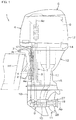
- a vessel propulsion apparatus 1 includes a clamp bracket 2 attachable to the rear portion (stern) of a hull H1, and an outboard motor 5 supported by the clamp bracket 2.
- the outboard motor 5 is rotatable around a steering axis As (centerline of the steering shaft 4) extending in the up-down direction with respect to the clamp bracket 2, and rotatable around a tilt axis At (centerline of a tilting shaft 3) extending in the left-right direction with respect to the clamp bracket 2.
- the outboard motor 5 includes an engine 6 as a non-limiting example of a prime mover that generates power to rotate the propeller 11, and a power transmitting device 7 configured to transmit power of the engine 6 to the propeller 11.
- the outboard motor 5 further includes a cowling 12 that covers the engine 6 and a casing 13 that houses the power transmitting device 7.
- the casing 13 includes an exhaust guide 14 disposed below the engine 6, an upper case 15 disposed below the exhaust guide 14, and a lower case 16 disposed below the upper case 15.
- the exhaust guide 14 as an engine support member supports the engine 6 in a posture in which the rotation axis Ac (rotation axis of the crankshaft) of the engine 6 is vertical.
- the power transmitting device 7 includes a drive shaft 8 to which rotation of the engine 6 is transmitted, a forward/reverse switching mechanism 9 to which rotation of the drive shaft 8 is transmitted, and a propeller shaft 10 to which rotation of the forward/reverse switching mechanism 9 is transmitted.
- Rotation of the engine 6 is transmitted to the propeller shaft 10 via the drive shaft 8 and the forward/reverse switching mechanism 9.
- the direction of the rotation to be transmitted from the drive shaft 8 to the propeller shaft 10 is switched by the forward/reverse switching mechanism 9.
- the propeller shaft 10 extends in the front-rear direction inside the lower case 16.
- the front-rear direction corresponds to the axial direction Da of the propeller shaft 10.
- the rear end portion of the propeller shaft 10 projects rearward from the lower case 16.
- the propeller 11 is removably attached to the rear end portion of the propeller shaft 10.
- the propeller 11 is rotatable around the propeller axis Ap (centerline of the propeller shaft 10) together with the propeller shaft 10.
- the outboard motor 5 includes a main exhaust passage 17 that guides exhaust air of the engine 6 to a main exhaust port 18 that opens into the water.
- the main exhaust passage 17 is defined by the casing 13 and the propeller 11.
- the main exhaust passage 17 extends downward from the engine 6 to the propeller shaft 10, and then extends rearward along the propeller shaft 10.
- the main exhaust passage 17 passes through the insides of the exhaust guide 14, the upper case 15, and the lower case 16 and is open at the rear end portion of the propeller 11.
- the rear end portion of the propeller 11 defines the main exhaust port 18. Exhaust air discharged from the engine 6 is exhausted into the water from the rear end portion of the propeller 11 through the main exhaust passage 17.
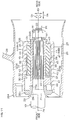
- the propeller 11 includes a tubular propeller member 24 including a plurality of blades 28, a tubular damper unit 30 to be disposed inside the propeller member 24, an annular front spacer 29 to be disposed ahead of the damper unit 30, and a discoid rear spacer 33 to be disposed at the rear of the damper unit 30.
- the damper unit 30 includes a tubular bushing 31 to be spline-coupled to the propeller shaft 10, and a tubular propeller damper 32 held by the bushing 31. As shown in Fig.
- the propeller shaft 10 includes a tapered portion 21 to which the front spacer 29 is attached, a spline shaft portion 22 to be spline-coupled to the bushing 31 and the rear spacer 33, and a male threaded portion 23 to which a washer W1 and a nut N1 are attached.
- the propeller member 24 includes an inner cylinder 25 extending in the axial direction Da, an outer cylinder 27 coaxially surrounding the inner cylinder 25 at a distance in the radial direction Dr of the propeller shaft 10, a plurality of (for example, three) ribs 26 extending from the outer circumferential surface of the inner cylinder 25 to the inner circumferential surface of the outer cylinder 27, and a plurality of blades 28 extending outward from the outer circumferential surface of the outer cylinder 27.
- the inner cylinder 25, the ribs 26, the outer cylinder 27, and the blades 28 are preferably integral with each other.
- the outer circumferential surface of the inner cylinder 25 and the inner circumferential surface of the outer cylinder 27 define a portion of the main exhaust passage 17.
- the rear end portion of the outer cylinder 27 defines the main exhaust port 18.
- the inner cylinder 25 includes an annular flange portion 34 surrounding the propeller shaft 10, and a second cylindrical portion 35 extending rearward from the outer circumferential portion of the flange portion 34.
- the damper unit 30 is disposed inside the second cylindrical portion 35.
- the inner diameter of the rear end of the second cylindrical portion 35 is larger than the outer diameter of the damper unit 30.
- the inner diameter of the flange portion 34 is smaller than the outer diameter of the damper unit 30.
- the rear end of the second cylindrical portion 35 defines an inlet from which the damper unit 30 enters the second cylindrical portion 35.
- the damper unit 30 is inserted into the second cylindrical portion 35 in the forward direction from the rear side of the propeller member 24.
- the front spacer 29 includes a tapered inner circumferential surface 29i along the outer circumferential surface of the tapered portion 21 of the propeller shaft 10, a tubular fitting portion 29a fitted in the flange portion 34 of the inner cylinder 25, and an annular support portion 29b disposed ahead of the flange portion 34 of the inner cylinder 25.
- the fitting portion 29a is disposed ahead of the bushing 31.
- the front end surface of the bushing 31 is pressed against the rear end surface of the fitting portion 29a.
- the outer circumferential surface of the fitting portion 29a is surrounded by the flange portion 34 of the inner cylinder 25.
- the support portion 29b preferably has a discoid shape, for example, coaxial with the fitting portion 29a, and has an outer diameter larger than that of the fitting portion 29a.
- the rear end surface of the support portion 29b supports the front end surface of the flange portion 34 of the inner cylinder 25.
- the rear spacer 33 is spline-coupled to the spline shaft portion 22 of the propeller shaft 10.
- a plurality of teeth provided on the spline shaft portion 22 engage with a plurality of teeth provided on a spline hole 33s of the rear spacer 33.
- the outer circumferential surface 33o of the rear spacer 33 is surrounded by the second cylindrical portion 35 of the inner cylinder 25.
- the outer circumferential surface 33o of the rear spacer 33 is preferably a cylindrical surface with a constant outer diameter.
- the outer diameter of the rear spacer 33 is smaller than the inner diameter of the second cylindrical portion 35 of the inner cylinder 25, and larger than the inner diameter of the flange portion 34 of the inner cylinder 25.
- the front end surface 33f of the rear spacer 33 is pressed against the rear end surface of the bushing 31, and opposed to the rear end surface of the propeller damper 32 in the axial direction Da at a distance.
- the front end surface of the washer W1 is pressed against the rear end surface 33r of the rear spacer 33.
- the damper unit 30 is inserted in advance into the inner cylinder 25 of the propeller member 24. Then, after the front spacer 29 is attached to the propeller shaft 10, the propeller unit including the propeller member 24 and the damper unit 30 integral with each other is spline-coupled to the propeller shaft 10. That is, the spline shaft portion 22 of the propeller shaft 10 is spline-coupled to the bushing 31 of the damper unit 30. Thereafter, the rear spacer 33 is attached to the spline shaft portion 22 of the propeller shaft 10, and the washer W1 and the nut N1 are attached to the male threaded portion 23 of the propeller shaft 10. A pin P1 that prevents the nut N1 from loosening is inserted into a through-hole passing through the nut N1 and the propeller shaft 10 in the radial direction Dr. Accordingly, the propeller 11 is attached to the propeller shaft 10.
- the inner cylinder 25 includes, in addition to the flange portion 34 and the second cylindrical portion 35, a plurality of (for example, three) second protrusions 36 protruding inward (direction approaching the propeller axis Ap) from the inner circumferential surface of the second cylindrical portion 35, and a plurality of (for example, twelve) engagement protrusions 37 protruding inward from the inner circumferential surface of the second cylindrical portion 35.
- a plurality of (for example, three) second protrusions 36 protruding inward (direction approaching the propeller axis Ap) from the inner circumferential surface of the second cylindrical portion 35
- a plurality of (for example, twelve) engagement protrusions 37 protruding inward from the inner circumferential surface of the second cylindrical portion 35.
- the three second protrusions 36 are disposed at equal intervals in, for example, the circumferential direction Dc of the propeller shaft 10.
- the twelve engagement protrusions 37 are disposed at equal intervals in, for example, the circumferential direction Dc.
- the inner cylinder 25 is viewed from the rear side thereof, the three engagement protrusions 37 overlap the three second protrusions 36, respectively.
- the second protrusion 36 and the engagement protrusion 37 overlapping each other are disposed so that the center of the second protrusion 36 in the circumferential direction Dc and the center of the engagement protrusion 37 in the circumferential direction Dc are positioned on the same radius.
- the height (length in the radial direction Dr) of the second protrusion 36 from the inner circumferential surface of the second cylindrical potion 35 is higher than the height of the engagement protrusion 37 from the inner circumferential surface of the second cylindrical portion 35.
- the width (length in the circumferential direction Dc) of the second protrusion 36 is larger than the width of the engagement protrusion 37.
- the second protrusions 36 and the engagement protrusions 37 extend in the axial direction Da along the inner circumferential surface of the second cylindrical portion 35.
- the second protrusions 36 extend rearward from the flange portion 34 of the inner cylinder 25.
- the second protrusions 36 are shorter in the axial direction Da than any of the engagement protrusions 37.
- the outer surface of the second protrusion 36 includes a pair of side surfaces 36L extending in the axial direction Da and the radial direction Dr, and a tip end surface 36a that joins the inner ends of the pair of side surfaces 36L to each other.
- the pair of side surfaces 36L of the second protrusion 36 preferably have tapering shapes so that the distance between the pair of side surfaces 36L continuously and gradually decreases as the tip end surface 36a of the second protrusion 36 is approached.
- the distance between the pair of side surfaces 36L of the second protrusion 36 is the same at any position in the axial direction Da as long as their positions are the same in the radial direction Dr.
- the tip end surface 36a of the second protrusion 36 preferably has an arc shape coaxial with the inner circumferential surface of the second cylindrical portion 35 of the inner cylinder 25.
- the height of the second protrusion 36 is the same at any position in the axial direction Da.
- the width of the tip end surface 36a of the second protrusion 36 is the same at any position in the axial direction Da.
- the twelve engagement protrusions 37 include a plurality of (for example, six) first engagement protrusions 37A, the rear ends of which are disposed more rearward than the second protrusions 36, and a plurality of (for example, six) second engagement protrusions 37B, the rear ends of which are disposed more rearward than the first engagement protrusions 37A.
- Each second engagement protrusion 37B includes a short protrusion 37B1 disposed at the rear of the second protrusion 36, and a long protrusion 37B2 longer than the short protrusion 37B1.
- the front end of the short protrusion 37B1 is disposed at the rear of the second protrusion 36.
- the front end of the long protrusion 37B2 is disposed more forward than the rear end of the second protrusion 36.
- the first engagement protrusions 37A are shorter in the axial direction Da than any of the second engagement protrusions 37B.
- the twelve engagement protrusions 37 are disposed at equal intervals in, for example, the circumferential direction Dc in the order of the first engagement protrusion 37A, the short protrusion 37B1, and the long protrusion 37B2.
- the outer surface of the engagement protrusion 37 includes a pair of side surfaces 37L extending in the axial direction Da and the radial direction Dr, and a tip end surface 37a that joins the inner ends of the pair of side surfaces 37L to each other.
- the pair of side surfaces 37L of the engagement protrusion 37 preferably have tapering shapes so that the distance between the pair of side surfaces 37L continuously decreases as the tip end surface 37a of the engagement protrusion 37 is approached.
- the pair of side surfaces 37L of the engagement protrusion 37 are inclined with respect to the propeller axis Ap so that the distance between the pair of side surfaces 37L decreases as the rear end of the engagement protrusion 37 is approached.
- the pair of side surfaces 37L of the engagement protrusion 37 preferably have tapering shapes so that the distance between the pair of side surfaces 37L continuously decreases as the rear end of the engagement protrusion 37 is approached.
- the tip end surface 37a of the engagement protrusion 37 is preferably tapered so that the width of the tip end surface 37 continuously decreases as the rear end of the engagement protrusion 37 is approached.
- the tip end surface 37a of the engagement protrusion 37 is inclined with respect to the propeller axis Ap so as to separate from the propeller axis Ap as the rear end of the engagement protrusion 37 is approached.
- the engagement protrusion 37 is preferably tapered so that the height of the engagement protrusion 37 continuously decreases as the rear end of the engagement protrusion 37 is approached.
- each of the first engagement protrusions 37A and the second engagement protrusions 37B includes a first transmitting protrusion 38 configured to transmit a torque to rotate the propeller shaft 10 and the propeller member 24 relative to each other (hereinafter, referred to as "rotary torque") between the propeller damper 32 and the inner cylinder 25 regardless of the magnitude of the torque.
- Each second engagement protrusion 37B further includes a second transmitting protrusion 39 (refer to Fig. 8C ) configured to transmit the rotary torque between the propeller damper 32 and the inner cylinder 25 when the torque is not less than a first torque T1 (refer to Fig. 9 ).
- Fig. 7C is a sectional view of the damper unit 30 taken along a vertical plane passing through the propeller axis Ap.
- the bushing 31 includes a first cylindrical portion 40 extending in the axial direction Da.
- the first cylindrical portion 40 includes a spline hole 40s extending forward from the rear end of the first cylindrical portion 40, an inner circumferential surface 40i extending forward from the spline hole 40s, and a cylindrical outer circumferential surface 40o extending in the axial direction Da.
- the outer circumferential surface 40o and the inner circumferential surface 40i of the first cylindrical portion 40 are cylindrical surfaces whose outer diameters are constant.
- the centerline of the first cylindrical portion 40 (centerline of the bushing 31) is disposed on the propeller axis Ap.
- the plurality of teeth provided on the spline shaft portion 22 of the propeller shaft 10 are engaged with the plurality of teeth provided on the spline hole 40s of the first cylindrical portion 40. Accordingly, the bushing 31 rotates together with the propeller shaft 10.
- Fig. 7D is a front view of the damper unit 30 viewed from the front side.
- the bushing 31 includes a plurality of (for example, three) first protrusions 41 extending outward from the first cylindrical portion 40.
- the three first protrusions 41 are disposed at equal intervals in, for example, the circumferential direction Dc.
- the first protrusions 41 are integral with the first cylindrical portion 40. Accordingly, the first protrusions 41 rotate together with the first cylindrical portion 40 and the propeller shaft 10.
- the bushing 31 is made of metal, and higher in strength than the propeller damper 32. As shown in Fig.
- the first protrusions 41 extend outward from the front portion of the outer circumferential surface 40o of the first cylindrical portion 40.
- the first protrusions 41 are disposed more rearward than the front end of the first cylindrical portion 40.
- the first protrusions 41 are disposed more forward than the spline hole 40s of the bushing 31.
- the first protrusions 41 are shorter in the axial direction Da than the first cylindrical portion 40.
- the outer surface of the first protrusion 41 of the bushing 31 includes a pair of side surfaces 41L extending in the axial direction Da and the radial direction Dr, and a tip end surface 41a that joins the outer ends of the pair of side surfaces 41L to each other.
- the distance between the pair of side surfaces 41L of the first protrusion 41 is constant at any position in the axial direction Da and the radial direction Dr.
- the tip end surface 41a of the first protrusion 41 preferably has an arc shape coaxial with the outer circumferential surface 40o of the first cylindrical portion 40.
- the height of the first protrusion 41 is the same at any position in the axial direction Da.
- the height of the first protrusion 41 is larger than the thickness of the first cylindrical portion 40, that is, the distance in the radial direction Dr from the inner circumferential surface 40i of the first cylindrical portion 40 to the outer circumferential surface 40o of the first cylindrical portion 40.
- the width of the tip end surface 41a of the first protrusion 41 is the same at any position in the axial direction Da.
- the propeller damper 32 is preferably made of an elastic material that is elastically deformable such as rubber or resin, for example.
- the propeller damper 32 surrounds the first cylindrical portion 40 of the bushing 31.
- the propeller damper 32 is longer in the axial direction Da than the first protrusions 41 of the bushing 31, and shorter in the axial direction Da than the first cylindrical portion 40 of the bushing 31.
- the propeller damper 32 is disposed at a position more rearward than the first protrusions 41 and more forward than the rear end of the first cylindrical portion 40.
- the inner circumferential surface 42i and the inner circumferential surface 43i of the propeller damper 32 are fixed to the outer circumferential surface 40o of the first cylindrical portion 40 of the bushing 31 by, for example, vulcanization bonding.
- the height of the propeller damper 32 is higher than the heights of the first protrusions 41.
- the outer surface 42o and outer surface 43o of the propeller damper 32 are disposed more outward than the tip end surfaces 41a of the first protrusions 41.
- the propeller damper 32 includes a tubular first damper 42 configured to transmit a rotary torque between the bushing 31 and the inner cylinder 25 regardless of the magnitude of the torque, and a tubular second damper 43 configured to transmit a rotary torque between the bushing 31 and the inner cylinder 25 when the torque is not less than the first torque T1 (refer to Fig. 9 ).
- the first damper 42 and the second damper 43 are arranged side by side in the axial direction Da so that the first damper 42 is positioned ahead of the second damper 43.
- the first damper 42 is longer in the axial direction Da than the second damper 43.
- the first damper 42 and the second damper 43 define a single integral member.
- the inner circumferential surface 42i of the first damper 42 and the inner circumferential surface 43i of the second damper 43 are fixed to the outer circumferential surface 40o of the first cylindrical portion 40 of the bushing 31.
- the outer diameter of the first damper 42 decreases as the front end of the first damper 42 is approached.
- the outer diameter of the second damper 43 is smaller than the outer diameter (maximum outer diameter) of the rear end of the first damper 42.
- the outer diameter of the second damper 43 is the same at any position in the axial direction Da.
- the propeller damper 32 includes a plurality of (for example, twelve) engagement grooves 44 that engage with the plurality of engagement protrusions 37 provided on the inner cylinder 25.
- the plurality of engagement grooves 44 include a plurality of
- first engagement grooves 44A that engage with the plurality of first engagement protrusions 37A provided on the inner cylinder 25, and a plurality of (for example, six) second engagement grooves 44B that engage with the plurality of second engagement protrusions 37B provided on the inner cylinder 25.
- the twelve engagement grooves 44 are disposed at equal intervals in the circumferential direction Dc so that the first engagement groove 44A and the second engagement groove 44B are alternately arranged.
- each first engagement groove 44A includes a first transmitting groove 45 inside of which the first transmitting protrusion 38 of the first engagement protrusion 37A is disposed, and a relief groove 46 disposed more rearward than the rear end of the first engagement protrusion 37A.
- Each second engagement groove 44B includes a first transmitting groove 45 inside of which the first transmitting protrusion 38 of the second engagement protrusion 37B is disposed, and a second transmitting groove 47 inside of which the second transmitting protrusion 39 of the second engagement protrusion 37B is disposed.
- the first transmitting grooves 45 are provided on the first damper 42, and the relief grooves 46 and the second transmitting grooves 47 are provided on the second damper 43.
- the first transmitting grooves 45, the relief grooves 46, and the second transmitting grooves 47 extend in the axial direction Da along the outer circumferential portion of the propeller damper 32.
- the front ends of the first transmitting grooves 45 are open at the front end surface of the propeller damper 32.
- the rear ends of the relief grooves 46 and the second transmitting grooves 47 are open at the rear end surface of the propeller damper 32.
- the rear ends of the first transmitting grooves 45 provided in the second engagement grooves 44B are open at the front end surfaces 47f of the second transmitting grooves 47.
- the first transmitting groove 45 and the relief groove 46 of the first engagement groove 44A continue toward each other in the axial direction Da.
- first transmitting groove 45 and the second transmitting groove 47 of the second engagement groove 44B continue toward each other in the axial direction Da.
- the relief grooves 46 and the second transmitting grooves 47 are shorter in the axial direction Da than the first transmitting grooves 45.
- the length of the relief groove 46 in the axial direction Da is equal to the length of the second transmitting groove 47 in the axial direction Da.
- the inner surface of the first transmitting groove 45 includes a pair of side surfaces 45L extending in the axial direction Da ad the radial direction Dr, and a bottom surface 45b that joins the inner ends of the pair of side surfaces 45L to each other.
- the pair of side surfaces 45L of the first transmitting groove 45 extend inward from the outer surface 42o of the first damper 42.
- the pair of side surfaces 45L of the first transmitting groove 45 preferably have tapering shapes so that the distance between the pair of side surfaces 45L continuously decreases as the propeller axis Ap is approached.
- the pair of side surfaces 45L of the first transmitting groove 45 preferably have tapering shapes so that the distance between the pair of side surfaces 45L continuously decreases as the rear end of the first transmitting groove 45 is approached.
- the bottom surface 45b of the first transmitting groove 45 is inclined with respect to the propeller axis Ap so as to approach the propeller axis Ap as the front end of the bottom surface 45b of the first transmitting groove 45 is approached.
- the angle of the bottom surface 45b of the first transmitting groove 45 with respect to the propeller axis Ap is equal to the angle of the outer surface 42o of the first damper 42 with respect to the propeller axis Ap.
- the inner surface of the relief groove 46 includes a pair of side surfaces 46L extending in the axial direction Da and the radial direction Dr, and a bottom surface 46b that joins the inner ends of the pair of side surfaces 46L to each other.
- the pair of side surfaces 46L of the relief groove 46 extend inward from the outer surface 43o of the second damper 43.
- the pair of side surfaces 46L of the relief groove 46 preferably have tapering shapes so that the distance between the pair of side surfaces 46L continuously decreases as the propeller axis Ap is approached.
- the distance between the pair of side surfaces 46L of the relief groove 46 is the same at any position in the axial direction Da as long as their positions are the same in the radial direction Dr.
- the angle of the bottom surface 46b of the relief groove 46 with respect to the propeller axis Ap is equal to the angle of the outer surface 43o of the second damper 43 with respect to the propeller axis Ap.
- the inner surface of the second transmitting groove 47 includes a pair of side surfaces 47L extending in the axial direction Da and the radial direction Dr, a bottom surface 47b that joins the inner ends of the pair of side surfaces 47L to each other, and a front end surface 47f that joins the front ends of the pair of side surfaces 47L to each other.
- the pair of side surfaces 47L of the second transmitting groove 47 extend rearward from the front end surface 47f of the second transmitting groove 47, and extends inward from the outer surface 43o of the second damper 43.
- the pair of side surfaces 47L of the second transmitting groove 47 preferably have tapering shapes so that the distance between the pair of side surfaces 47L continuously decreases as the propeller axis Ap is approached.
- the distance between the pair of side surfaces 47L of the second transmitting groove 47 is the same at any position in the axial direction Da as long as their positions are the same in the radial direction Dr.
- the bottom surface 47b of the second transmitting groove 47 preferably has an arc shape coaxial with the outer surface 43o of the second damper 43.
- the depth of the second transmitting groove 47 is the same at any position in the axial direction.
- the width of the bottom surface 47b of the second transmitting groove 47 is the same at any position in the axial direction Da.
- the six relief grooves 46 and the six second transmitting grooves 47 are disposed at equal intervals in, for example, the circumferential direction Dc so that the relief groove 46 and the second transmitting groove 47 are alternately arranged.
- the first transmitting groove 45 and the second transmitting groove 47 provided in the same second engagement groove 44B are disposed so that the center of the first transmitting groove 45 in the circumferential direction Dc and the center of the second transmitting groove 5 in the circumferential direction Dc are positioned on the same radius.
- the bushing 31 and the propeller damper 32 are disposed so that the center of the first protrusion 41 in the circumferential direction Dc and the center of the first transmitting groove 45 in the circumferential direction Dc are positioned on the same radius.
- the width of the second transmitting groove 47 is larger than the width of the first transmitting groove 45, and larger than the width of the relief groove 46.
- the depth of the second transmitting groove 47 is larger than the depth of the relief grove 46.
- the second damper 43 includes a plurality of (for example, six) outer circumferential protrusions 43a defined by the plurality of second transmitting grooves 47.
- the six relief grooves 46 are provided on the six outer circumferential protrusions 43a, respectively.
- the width of the second transmitting groove 47 is larger than the width of the outer circumferential protrusion 43a.
- the second transmitting groove 47 is longer in the axial direction Da than the first protrusion 41 of the bushing 31.
- the width of the second transmitting groove 47 is smaller than the width of the first protrusion 41.
- the damper unit 30 When fitting the damper unit 30 to the propeller member 24, the damper unit 30 is inserted into the inner cylinder 25 of the propeller member 24 so that the plurality of engagement protrusions 37 provided on the inner cylinder 25 are disposed inside the plurality of engagement grooves 44 provided on the propeller damper 32.
- each of the first engagement protrusions 37A and the second engagement protrusions 37B of the inner cylinder 25 includes a first transmitting protrusion 38 to be disposed inside the first transmitting groove 45 of the propeller damper 32.
- the width of the first transmitting groove 45 before the damper unit 30 is fitted to the propeller member 24 is smaller than the width of the first transmitting protrusion 38. Therefore, when the damper unit 30 is fitted to the propeller member 24, the first transmitting protrusions 38 are press-fitted into the first transmitting grooves 45, and due to elastic deformation of the propeller damper 32, the first transmitting grooves 45 are pushed and widened in the circumferential direction Dc.
- the pair of side surfaces 37L of the engagement protrusion 37 are pressed against the pair of side surfaces 45L of the first transmitting groove 45, respectively.
- the tip end surfaces 37a of the engagement protrusions 37 come into contact with the bottom surfaces 45b of the first transmitting grooves 45, and the outer surface 42o of the first damper 42 comes into contact with the inner circumferential surface of the second cylindrical portion 35 of the inner cylinder 25.
- the second engagement protrusion 37B of the inner cylinder 25 includes a second transmitting protrusion 39 to be disposed inside the second transmitting groove 47 of the propeller damper 32.
- the width of the second transmitting groove 47 is larger than the width of the second transmitting protrusion 39. Therefore, when the damper 30 is fitted to the propeller member 24, the second transmitting protrusions 39 are disposed inside the second transmitting grooves 47 in a state in which the second transmitting protrusions 39 and the second transmitting grooves 47 are separated from each other in the circumferential direction Dc.
- the second transmitting protrusions 39 and the second transmitting grooves 47 are disposed so that the center of the second transmitting protrusion 39 in the circumferential direction Dc and the center of the second transmitting groove 47 in the circumferential direction Dc are positioned on the same radius.
- the tip end surfaces 37a of the engagement protrusions 37 are separated from the propeller damper 32, and the outer surface 43o of the second damper 43 is separated from the inner circumferential surface of the second cylindrical portion 35 of the inner cylinder 25.
- the bushing 31 and the inner cylinder 25 are disposed at noncontact positions at which the side surfaces 47L of the second transmitting grooves 47 are separated in the circumferential direction Dc from the second transmitting protrusions 39 of the second engagement protrusions 37B.
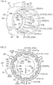
- each first protrusion 41 is disposed between two second protrusions 36.
- the center of the first protrusion 41 in the circumferential direction Dc is disposed at the center of the two second protrusions 36 in the circumferential direction Dc.
- the tip end surfaces 41a of the first protrusions 41 of the bushing 31 are separated from the inner cylinder 25, and the tip end surfaces 36a of the second protrusions 36 of the inner cylinder 25 are separated from the bushing 31.
- the bushing 31 and the inner cylinder 25 are disposed so that the side surfaces 47L of the second transmitting grooves 47 of the propeller damper 32 are separated from the second transmitting protrusions 39 of the second engagement protrusions 37B in the circumferential direction Dc, and the first protrusions 41 of the bushing 31 are disposed at noncontact positions separated in the circumferential direction Dc from the second protrusions 36 of the inner cylinder 25.
- Fig. 9 is a graph showing the relationship between the operating angle of the propeller damper 32 and the rotary torque to be applied to the propeller damper 32.
- the bushing 31 and the second damper 43 are separated from the inner cylinder 25, and the first damper 42 is in contact with the inner cylinder 25. Therefore, at this time, the inner cylinder 25 is elastically supported by the bushing 31 via only the first damper 42.
- this torque is transmitted between the bushing 31 and the inner cylinder 25 by the first damper 42 via the contact portions between the first transmitting protrusions 38 of the inner cylinder 25 and the first transmitting grooves 45 of the propeller damper 32. Further, the rotary torque is applied to the propeller damper 32, accordingly, the propeller damper 32 elastically deforms so that the outer circumferential portion and the inner circumferential portion of the first damper 42 rotate relative to each other, and the bushing 31 and the inner cylinder 25 rotate relative to each other by an angle corresponding to the elastic deformation amount of the propeller damper 32.
- the bushing 31 and the inner cylinder 25 are disposed at intermediate contact positions at which the side surfaces of the outer circumferential protrusions 43a of the second damper 43 (side surfaces 47L of the second transmitting grooves 47) come into contact with the side surfaces 37L of the engagement protrusions 37 of the inner cylinder 25.
- the first protrusions 41 of the bushing 31 are separated from the second protrusions 36 of the inner cylinder 25, so that the torque is transmitted by only the first damper 42 and the second damper 43.
- the operating angle of the propeller damper 32 increases to the second operating angle ⁇ 2.
- the bushing 31 and the inner cylinder 25 are disposed at contact positions at which the side surfaces 41L of the first protrusions 41 of the bushing 31 come into contact with the side surfaces 36L of the second protrusions 36 of the inner cylinder 25. Therefore, the rotary torque applied to the damper unit 30 is transmitted between the bushing 31 and the inner cylinder 25 by, in addition to the first damper 42 and the second damper 43, the first protrusions 41 and the second protrusions 36.
- the bushing 31 and the inner cylinder 25 are restricted from rotating relative to each other by the contact between the first protrusions 41 and the second protrusions 36, so that as shown in Fig. 9 , the operating angle of the propeller damper 32 is kept at the second operating angle ⁇ 2. That is, in this range, while the operating angle of the propeller damper 32 is kept at the second operating angle ⁇ 2 corresponding to the maximum operating angle, the bushing 31 and the inner cylinder 25 rotate together with each other. Accordingly, the torque is efficiently transmitted between the propeller shaft 10 and the propeller member 24.
- the propeller damper 32 that is elastically deformable is disposed between the bushing 31 and the inner cylinder 25.
- the inner cylinder 25 is disposed at the noncontact position in which the first protrusions 41 of the bushing 31 and the second protrusions 36 of the inner cylinder 25 are separated from each other in the circumferential direction Dc.
- the bushing 31 and the inner cylinder 25 are joined to each other via the propeller damper 32.
- the first protrusions 41 that determine the maximum operating angle of the propeller damper 32 are integral with the first cylindrical portion 40 of the bushing 31. Therefore, the width of variation in position of the first protrusions 41 with respect to the first cylindrical portion 40 is reduced to be smaller than in the case where the first protrusions 41 are provided on a member separate from the bushing 31. In other words, the width of variation in position of the first protrusions 41 with respect to the propeller damper 32 is reduced. Therefore, the maximum operating angle is increased, and performance of the propeller damper 32 is improved.
- the rear spacer 33 is disposed at the rear of the bushing 31, and the nut N1 is disposed at the rear of the rear spacer 33.
- the bushing 31 is pushed forward via the rear spacer 33, and accordingly, the bushing 31 is fixed in the front-rear direction with respect to the propeller shaft 10.
- the first protrusions 41 that determine the maximum operating angle of the propeller damper 32 are provided not on the rear spacer 33 but on the bushing 31. Therefore, the shape of the rear spacer 33 is made simpler than in the case where the first protrusions 41 are provided on the rear spacer 33.
- the engagement protrusions 37 of the inner cylinder 25 are disposed inside the engagement grooves 44 of the propeller damper 32.
- a torque applied to the propeller damper 32 is transmitted to the inner cylinder 25 by pushing the side surfaces 37L of the engagement protrusions 37 in the circumferential direction Dc by the side surfaces of the engagement grooves 44. Therefore, the torque transmission efficiency is made higher than in the case where the torque is transmitted by friction. Accordingly, the torque is efficiently transmitted between the propeller damper 32 and the inner cylinder 25.
- the side surfaces 45L of the first transmitting grooves 45 provided on the propeller damper 32 are always in contact with the side surfaces 37L of the first transmitting protrusions 38 provided on the inner cylinder 25. Therefore, from the beginning of generation of a torque to rotate the propeller shaft 10 and the inner cylinder 25 relative to each other, the torque is transmitted between the propeller damper 32 and the inner cylinder 25. Accordingly, the torque is efficiently transmitted between the propeller damper 32 and the inner cylinder 25.
- the width of the second protrusion 36 in the circumferential direction Dc is larger than the width of the engagement protrusion 37 in the circumferential direction Dc. Since the width of the second protrusion 36 is larger than the width of the engagement protrusion 37, the second protrusion 36 has a strength higher than that of the engagement protrusion 37. Therefore, when the first protrusions of the bushing 31 come into contact with the second protrusions 36 of the inner cylinder 25, the torque is reliably transmitted between the bushing 31 and the inner cylinder 25.
- the first transmitting groove 45 and the second transmitting groove 47 that are different in length in the circumferential direction Dc from each other are provided in each second engagement groove 44B of the propeller damper 32.
- the width (length in the circumferential direction Dc) of the second transmitting groove 47 is larger than the width of the first transmitting groove 45, so that when a torque to rotate the propeller member 24 and the propeller shaft 10 relative to each other is not generated, the side surfaces 47L of the second transmitting grooves 47 are separated in the circumferential direction Dc from the side surfaces 37L of the engagement protrusions 37.
- the side surfaces 47L of the second transmitting grooves 47 come into contact with the side surfaces 37L of the engagement protrusions 37 and push the engagement protrusions 37 in the circumferential direction Dc. Accordingly, the torque is transmitted from the side surfaces of both of the first transmitting grooves 45 and the second transmitting grooves 47. Therefore, by providing the first transmitting groove 45 and the second transmitting groove 47, which are different in length in the circumferential direction Dc from each other in each second engagement groove 44B, the characteristics (elastic coefficient) of the propeller damper 32 is changed in a phased manner.
- the propeller damper 32 is inserted in the inserting direction (forward direction) into the inner cylinder 25.
- the engagement protrusions 37 provided on the inner cylinder 25 increase in height toward the inserting direction. In other words, the engagement protrusions 37 decrease in height as the inlet of the inner cylinder 25 is approached. Therefore, the propeller damper 32 is easily inserted into and easily pulled out from the inner cylinder 25. Accordingly, the time necessary for assembling and maintenance of the propeller 11 is shortened.
- a propeller member 224 according to the second preferred embodiment of the present invention includes, instead of the inner cylinder 25 according to the first preferred embodiment of the present invention, an inner cylinder 225 according to the second preferred embodiment of the present invention.
- the inner cylinder 225 includes an annular flange portion 34 surrounding the propeller shaft 10, a second cylindrical portion 35 extending forward from the outer circumferential portion of the flange portion 34, and a tubular centering portion 248 extending rearward from the inner circumferential portion of the flange portion 34.
- the inner diameter of the front end of the second cylindrical portion 35 is larger than the outer diameter of the damper unit 30.
- the inner diameter of the flange portion 34 is smaller than the outer diameter of the damper unit 30.
- the damper unit 30 defines an inlet of the inside of the second cylindrical portion 35.
- the damper unit 30 is inserted rearward into the second cylindrical portion 35 from the front side of the propeller member 224.
- the first cylindrical portion 40 of the bushing 31 is sandwiched by the front spacer 29 and the washer W1 in the axial direction Da.
- the support portion 29b of the front spacer 29 is disposed inside the second cylindrical portion 35 of the inner cylinder 225.
- the rear end surface of the support portion 29b of the front spacer 29 is supported from the rear by the second cylindrical portion 35 of the inner cylinder 225.
- the centering portion 248 surrounds the first cylindrical portion 40 of the bushing 31.
- the centering portion 248 is disposed at the rear of the propeller damper 32.
- the centering portion 248 of the inner cylinder 225 is disposed around the bushing 31.
- the inner circumferential surface of the centering portion 248 surrounds the outer circumferential surface 41o of the first cylindrical portion 40 of the bushing 31, and is opposed to the outer circumferential surface 410 of the first cylindrical portion 40 of the bushing 31 in the radial direction Dr.
- the bushing 31 and the inner cylinder 225 are restricted from moving relative to each other in the radial direction Dr by contact between the outer circumferential surface 41o of the first cylindrical portion 40 of the bushing 31 and the inner circumferential surface of the centering portion 248. Accordingly, the amount of eccentricity of the inner cylinder 225 with respect to the bushing 31 is significantly reduced or prevented. Therefore, deviation of the elastic deformation of the propeller damper 32 which is caused by eccentricity of the inner cylinder 225 is significantly reduced or prevented.
- the propeller damper 32 preferably includes the first damper 42 and the second damper 43 is disclosed.
- the propeller damper 32 does not include the second damper 43, but includes only the first damper 42.
- the propeller damper 32 preferably has a tubular shape surrounding the entire circumference of the bushing 31 is disclosed. However, it is also possible that the propeller damper 32 does not continue for the entire circumference. That is, the propeller damper 32 preferably includes a plurality of divided bodies divided in the circumferential direction Dc.
- each first engagement groove 44A provided on the propeller damper 32 preferably includes the first transmitting groove 45 and the relief groove 46 is disclosed.
- each first engagement groove 44A may not include the relief groove 46.
- the case where the first cylindrical portion 40 of the bushing 31 is preferably pushed forward by the rear spacer 33 is disclosed.
- the first cylindrical portion 40 of the bushing 31 may be pushed forward by the washer W1. That is, the rear spacer 33 may be omitted.
- the case where the first protrusions 41 of the bushing 31 preferably extend outward from the front portion of the first cylindrical portion 40 of the bushing 31 is disclosed.
- the first protrusions 41 of the bushing 31 may extend outward from the rear portion of the first cylindrical portion 40 of the bushing 31.
- the inserting direction of the bushing 31 into the inner cylinder 25 may be either the forward direction or the rearward direction.
- the case where the inner circumferential surface 42i and the inner circumferential surface 43i of the propeller damper 32 are preferably fixed to the bushing 31 by vulcanization bonding is disclosed.
- the inner circumferential surface of the propeller damper 32 may be fixed to the bushing 31 by a method (for example, press fitting or engagement between convexities and concavities) other than vulcanization bonding.
- the heights of the engagement protrusions 37 preferably increase toward the inserting direction (forward direction or rearward direction) of the propeller damper 32 into the inner cylinder 25 is disclosed.
- the heights of the engagement protrusions 37 may decrease toward the inserting direction, or may be constant from the front ends of the engagement protrusions 37 to the rear ends of the engagement protrusions 37.
Landscapes
- Chemical & Material Sciences (AREA)
- Engineering & Computer Science (AREA)
- Combustion & Propulsion (AREA)
- Mechanical Engineering (AREA)
- Ocean & Marine Engineering (AREA)
- Motor Power Transmission Devices (AREA)
- Shafts, Cranks, Connecting Bars, And Related Bearings (AREA)
Claims (5)
- Röhrenförmige Dämpfer-Einheit (30), die zwischen einer Propellerwelle (10) einer Wasserfahrzeug-Antriebsvorrichtung (1) und einem Propeller-Element (24) angeordnet wird, das eine Vielzahl von Flügeln (28) enthält, die sich an einer Außenfläche des Propeller-Elementes (24) befinden, wobei die Dämpfer-Einheit (30) umfasst:eine Buchse (31), die mittels Keilprofil-Verbindung mit der Propellerwelle (10) gekoppelt wird, einen ersten zylindrischen Abschnitt (40) sowie eine Vielzahl erster Vorsprünge (41) enthält, wobei der erste zylindrische Abschnitt (40) aus Metall besteht, der erste zylindrische Abschnitt (40) die Propellerwelle (10) umschließt, der erste zylindrische Abschnitt (40) ein Keilprofil-Loch (40s) enthält, das sich an einer Innenumfangsfläche des ersten zylindrischen Abschnitts (40) befindet, wobei die ersten Vorsprünge (41) integral mit dem ersten zylindrischen Abschnitt (40) ausgebildet sind; sowieeinen Propeller-Dämpfer (32), der aus einem elastischen Material besteht und um den ersten zylindrischen Abschnitt (40) der Buchse (31) herum angeordnet ist;dadurch gekennzeichnet, dassdie ersten Vorsprünge (41) von einem vorderen Abschnitt des ersten zylindrischen Abschnitts (40) nach außen vorstehen; undder Propeller-Dämpfer (32) an einer Position angeordnet ist, die weiter hinten liegt als die ersten Vorsprünge (41).
- Dämpfer-Einheit (30) nach Anspruch 1, wobei eine Höhe des Propeller-Dämpfers (32) größer ist als eine Höhe der ersten Vorsprünge (41).
- Dämpfer-Einheit (30) nach Anspruch 1 oder 2, wobei der Propeller-Dämpfer (32) an einer Position angeordnet ist, die weiter vorn liegt als ein hinteres Ende des ersten zylindrischen Abschnitts (40).
- Dämpfer-Einheit (30) nach einem der Ansprüche 1 bis 3, wobei der Propeller-Dämpfer (32) mittels Verkleben an einer Außenumfangsfläche des ersten zylindrischen Abschnitts (40) der Buchse (31) befestigt wird.
- Dämpfer-Einheit (30) nach einem der Ansprüche 1 bis 4, wobei der Propeller-Dämpfer (32) in einer axialen Richtung (Da) des ersten zylindrischen Abschnitts (40) länger ist als die ersten Vorsprünge (41) und in der axialen Richtung (Da) kürzer ist als der erste zylindrische Abschnitt (40).
Applications Claiming Priority (2)
| Application Number | Priority Date | Filing Date | Title |
|---|---|---|---|
| JP2014104634A JP2015217893A (ja) | 2014-05-20 | 2014-05-20 | 船舶推進機用のプロペラおよびこれを備えた船舶推進機 |
| EP15168384.4A EP2946999B1 (de) | 2014-05-20 | 2015-05-20 | Propeller für eine schiffsantriebsvorrichtung und schiffsantriebsvorrichtung damit |
Related Parent Applications (2)
| Application Number | Title | Priority Date | Filing Date |
|---|---|---|---|
| EP15168384.4A Division EP2946999B1 (de) | 2014-05-20 | 2015-05-20 | Propeller für eine schiffsantriebsvorrichtung und schiffsantriebsvorrichtung damit |
| EP15168384.4A Division-Into EP2946999B1 (de) | 2014-05-20 | 2015-05-20 | Propeller für eine schiffsantriebsvorrichtung und schiffsantriebsvorrichtung damit |
Publications (2)
| Publication Number | Publication Date |
|---|---|
| EP3144214A1 EP3144214A1 (de) | 2017-03-22 |
| EP3144214B1 true EP3144214B1 (de) | 2019-07-03 |
Family
ID=53268643
Family Applications (2)
| Application Number | Title | Priority Date | Filing Date |
|---|---|---|---|
| EP16181162.5A Active EP3144214B1 (de) | 2014-05-20 | 2015-05-20 | Röhrendämpfereinheit, die zwischen einer propellerwelle eines schiffsantriebs und einem propeller angeordnet ist |
| EP15168384.4A Active EP2946999B1 (de) | 2014-05-20 | 2015-05-20 | Propeller für eine schiffsantriebsvorrichtung und schiffsantriebsvorrichtung damit |
Family Applications After (1)
| Application Number | Title | Priority Date | Filing Date |
|---|---|---|---|
| EP15168384.4A Active EP2946999B1 (de) | 2014-05-20 | 2015-05-20 | Propeller für eine schiffsantriebsvorrichtung und schiffsantriebsvorrichtung damit |
Country Status (5)
| Country | Link |
|---|---|
| US (1) | US9776696B2 (de) |
| EP (2) | EP3144214B1 (de) |
| JP (1) | JP2015217893A (de) |
| CN (1) | CN105083517B (de) |
| TW (1) | TWI572525B (de) |
Cited By (1)
| Publication number | Priority date | Publication date | Assignee | Title |
|---|---|---|---|---|
| RU218621U1 (ru) * | 2023-04-10 | 2023-06-02 | Публичное Акционерное Общество "Одк-Сатурн" | Узел соединения фланцев судового валопровода |
Families Citing this family (10)
| Publication number | Priority date | Publication date | Assignee | Title |
|---|---|---|---|---|
| TWI608962B (zh) * | 2016-01-27 | 2017-12-21 | Solas Science & Engineering Co Ltd | Double-piece shaft sleeve for marine propeller and marine propeller using the same |
| CN107042882A (zh) * | 2016-02-05 | 2017-08-15 | 般若科技股份有限公司 | 船用螺旋桨的双节式轴套及船用螺旋桨 |
| JP2019151214A (ja) | 2018-03-02 | 2019-09-12 | ヤマハ発動機株式会社 | 船外機およびプロペラユニット用のダンパー部材 |
| US10864974B2 (en) * | 2018-08-01 | 2020-12-15 | Turning Point Propeilers, Inc. | Propeller assembly with hub structure which reduces gear noise during operation |
| US10875615B1 (en) * | 2018-08-20 | 2020-12-29 | Brunswick Corporation | Systems and methods for reducing porosity in propellers |
| US11299246B1 (en) | 2021-01-21 | 2022-04-12 | Turning Point Propellers, Inc. | Propeller assembly with noise reducing hub arrangement |
| JP2022150665A (ja) | 2021-03-26 | 2022-10-07 | ヤマハ発動機株式会社 | 船外機 |
| JP2023002211A (ja) | 2021-06-22 | 2023-01-10 | ヤマハ発動機株式会社 | 船舶推進機用のプロペラ及び船舶用推進機 |
| JP2023054607A (ja) * | 2021-10-04 | 2023-04-14 | ヤマハ発動機株式会社 | 船舶推進装置、プロペラユニット及び方法 |
| CN119343296B (zh) * | 2023-05-30 | 2025-09-09 | 广东逸动科技有限公司 | 起翘夹具、推进器及水域可移动设备 |
Family Cites Families (10)
| Publication number | Priority date | Publication date | Assignee | Title |
|---|---|---|---|---|
| US3865509A (en) | 1973-08-02 | 1975-02-11 | Brunswick Corp | Propeller construction |
| TW299294B (de) * | 1994-10-20 | 1997-03-01 | Honda Motor Co Ltd | |
| US6471481B2 (en) * | 2001-01-02 | 2002-10-29 | Turning Point Propellers, Inc. | Hub assembly for marine propeller |
| JP4416642B2 (ja) * | 2004-12-27 | 2010-02-17 | ヤマハ発動機株式会社 | 船外機 |
| JP4668745B2 (ja) * | 2005-09-07 | 2011-04-13 | ヤマハ発動機株式会社 | 船舶推進機用プロペラ緩衝装置 |
| US7717678B2 (en) * | 2006-11-14 | 2010-05-18 | Turning Point Propellers, Inc. | Spindle with overmolded bushing |
| JP2011178228A (ja) * | 2010-02-26 | 2011-09-15 | Yamaha Motor Co Ltd | 船舶推進機用プロペラおよびこれを備える船舶推進機 |
| JP2013121761A (ja) * | 2011-12-09 | 2013-06-20 | Suzuki Motor Corp | 船外機の排気構造 |
| CN202541815U (zh) * | 2012-03-09 | 2012-11-21 | 重庆银钢科技(集团)有限公司 | 一种阻尼缓冲螺旋桨系统 |
| JP5979018B2 (ja) | 2013-01-22 | 2016-08-24 | ヤマハ発動機株式会社 | プロペラユニット及びプロペラユニット用衝撃吸収部材 |
-
2014
- 2014-05-20 JP JP2014104634A patent/JP2015217893A/ja active Pending
-
2015
- 2015-03-23 TW TW104109230A patent/TWI572525B/zh active
- 2015-04-13 US US14/684,724 patent/US9776696B2/en active Active
- 2015-05-19 CN CN201510257127.6A patent/CN105083517B/zh active Active
- 2015-05-20 EP EP16181162.5A patent/EP3144214B1/de active Active
- 2015-05-20 EP EP15168384.4A patent/EP2946999B1/de active Active
Non-Patent Citations (1)
| Title |
|---|
| None * |
Cited By (1)
| Publication number | Priority date | Publication date | Assignee | Title |
|---|---|---|---|---|
| RU218621U1 (ru) * | 2023-04-10 | 2023-06-02 | Публичное Акционерное Общество "Одк-Сатурн" | Узел соединения фланцев судового валопровода |
Also Published As
| Publication number | Publication date |
|---|---|
| US20150336647A1 (en) | 2015-11-26 |
| CN105083517B (zh) | 2017-10-24 |
| JP2015217893A (ja) | 2015-12-07 |
| TW201544398A (zh) | 2015-12-01 |
| EP3144214A1 (de) | 2017-03-22 |
| EP2946999B1 (de) | 2020-07-01 |
| US9776696B2 (en) | 2017-10-03 |
| TWI572525B (zh) | 2017-03-01 |
| EP2946999A1 (de) | 2015-11-25 |
| CN105083517A (zh) | 2015-11-25 |
Similar Documents
| Publication | Publication Date | Title |
|---|---|---|
| EP2946999B1 (de) | Propeller für eine schiffsantriebsvorrichtung und schiffsantriebsvorrichtung damit | |
| US9400029B2 (en) | Damper unit for vessel propulsion apparatus, propeller for vessel propulsion apparatus, and vessel propulsion apparatus | |
| US7086836B1 (en) | Dual rate torque transmitting device for a marine propeller | |
| EP2491780A1 (de) | Schwingungsdämpfungsmechanismus und arbeitsmaschine damit | |
| JP4498385B2 (ja) | オイルポンプ駆動機構 | |
| EP1972542B1 (de) | Antriebswellenvorrichtung | |
| JP6895377B2 (ja) | 蠕動ポンプ | |
| KR20160095692A (ko) | 전동식 조향장치 | |
| WO2006002463A1 (en) | Interchangeable propeller hub system | |
| KR101444425B1 (ko) | 클러치 구조체 | |
| KR102130009B1 (ko) | 차량용 드라이브 샤프트 | |
| US10207781B2 (en) | Propeller unit of marine propulsion apparatus | |
| US10132396B2 (en) | Stator wheel of torque converter and torque converter | |
| KR101843276B1 (ko) | 등속조인트 | |
| EP3343055A1 (de) | Leistungsübertragungsvorrichtung | |
| KR102139697B1 (ko) | 등속조인트용 연결장치 | |
| KR101444422B1 (ko) | 클러치 구조체 | |
| KR101073093B1 (ko) | 자동차 프로펠러 샤프트 연결구조 | |
| JP2013083281A (ja) | 十字軸継手およびその製造方法 | |
| KR100800600B1 (ko) | 프로펠러 샤프트 어셈블리 | |
| KR101576995B1 (ko) | 전동식 파워 스티어링 장치의 모터 커플링 | |
| KR102157807B1 (ko) | 전동식 조향장치 | |
| JP2022191904A (ja) | プロペラユニット | |
| KR20140059041A (ko) | 트라이포드 타입 등속조인트 | |
| KR20170014938A (ko) | 선박 클러치 모듈 |
Legal Events
| Date | Code | Title | Description |
|---|---|---|---|
| PUAI | Public reference made under article 153(3) epc to a published international application that has entered the european phase |
Free format text: ORIGINAL CODE: 0009012 |
|
| STAA | Information on the status of an ep patent application or granted ep patent |
Free format text: STATUS: THE APPLICATION HAS BEEN PUBLISHED |
|
| AC | Divisional application: reference to earlier application |
Ref document number: 2946999 Country of ref document: EP Kind code of ref document: P |
|
| AK | Designated contracting states |
Kind code of ref document: A1 Designated state(s): AL AT BE BG CH CY CZ DE DK EE ES FI FR GB GR HR HU IE IS IT LI LT LU LV MC MK MT NL NO PL PT RO RS SE SI SK SM TR |
|
| STAA | Information on the status of an ep patent application or granted ep patent |
Free format text: STATUS: REQUEST FOR EXAMINATION WAS MADE |
|
| 17P | Request for examination filed |
Effective date: 20170914 |
|
| RBV | Designated contracting states (corrected) |
Designated state(s): AL AT BE BG CH CY CZ DE DK EE ES FI FR GB GR HR HU IE IS IT LI LT LU LV MC MK MT NL NO PL PT RO RS SE SI SK SM TR |
|
| GRAJ | Information related to disapproval of communication of intention to grant by the applicant or resumption of examination proceedings by the epo deleted |
Free format text: ORIGINAL CODE: EPIDOSDIGR1 |
|
| STAA | Information on the status of an ep patent application or granted ep patent |
Free format text: STATUS: GRANT OF PATENT IS INTENDED |
|
| GRAP | Despatch of communication of intention to grant a patent |
Free format text: ORIGINAL CODE: EPIDOSNIGR1 |
|
| INTG | Intention to grant announced |
Effective date: 20190130 |
|
| GRAS | Grant fee paid |
Free format text: ORIGINAL CODE: EPIDOSNIGR3 |
|
| GRAA | (expected) grant |
Free format text: ORIGINAL CODE: 0009210 |
|
| STAA | Information on the status of an ep patent application or granted ep patent |
Free format text: STATUS: THE PATENT HAS BEEN GRANTED |
|
| AC | Divisional application: reference to earlier application |
Ref document number: 2946999 Country of ref document: EP Kind code of ref document: P |
|
| AK | Designated contracting states |
Kind code of ref document: B1 Designated state(s): AL AT BE BG CH CY CZ DE DK EE ES FI FR GB GR HR HU IE IS IT LI LT LU LV MC MK MT NL NO PL PT RO RS SE SI SK SM TR |
|
| REG | Reference to a national code |
Ref country code: GB Ref legal event code: FG4D |
|
| REG | Reference to a national code |
Ref country code: CH Ref legal event code: EP Ref country code: AT Ref legal event code: REF Ref document number: 1150659 Country of ref document: AT Kind code of ref document: T Effective date: 20190715 |
|
| REG | Reference to a national code |
Ref country code: DE Ref legal event code: R096 Ref document number: 602015033371 Country of ref document: DE |
|
| REG | Reference to a national code |
Ref country code: IE Ref legal event code: FG4D |
|
| REG | Reference to a national code |
Ref country code: NL Ref legal event code: MP Effective date: 20190703 |
|
| REG | Reference to a national code |
Ref country code: LT Ref legal event code: MG4D |
|
| REG | Reference to a national code |
Ref country code: AT Ref legal event code: MK05 Ref document number: 1150659 Country of ref document: AT Kind code of ref document: T Effective date: 20190703 |
|
| PG25 | Lapsed in a contracting state [announced via postgrant information from national office to epo] |
Ref country code: CZ Free format text: LAPSE BECAUSE OF FAILURE TO SUBMIT A TRANSLATION OF THE DESCRIPTION OR TO PAY THE FEE WITHIN THE PRESCRIBED TIME-LIMIT Effective date: 20190703 Ref country code: FI Free format text: LAPSE BECAUSE OF FAILURE TO SUBMIT A TRANSLATION OF THE DESCRIPTION OR TO PAY THE FEE WITHIN THE PRESCRIBED TIME-LIMIT Effective date: 20190703 Ref country code: SE Free format text: LAPSE BECAUSE OF FAILURE TO SUBMIT A TRANSLATION OF THE DESCRIPTION OR TO PAY THE FEE WITHIN THE PRESCRIBED TIME-LIMIT Effective date: 20190703 Ref country code: PT Free format text: LAPSE BECAUSE OF FAILURE TO SUBMIT A TRANSLATION OF THE DESCRIPTION OR TO PAY THE FEE WITHIN THE PRESCRIBED TIME-LIMIT Effective date: 20191104 Ref country code: HR Free format text: LAPSE BECAUSE OF FAILURE TO SUBMIT A TRANSLATION OF THE DESCRIPTION OR TO PAY THE FEE WITHIN THE PRESCRIBED TIME-LIMIT Effective date: 20190703 Ref country code: AT Free format text: LAPSE BECAUSE OF FAILURE TO SUBMIT A TRANSLATION OF THE DESCRIPTION OR TO PAY THE FEE WITHIN THE PRESCRIBED TIME-LIMIT Effective date: 20190703 Ref country code: LT Free format text: LAPSE BECAUSE OF FAILURE TO SUBMIT A TRANSLATION OF THE DESCRIPTION OR TO PAY THE FEE WITHIN THE PRESCRIBED TIME-LIMIT Effective date: 20190703 Ref country code: NO Free format text: LAPSE BECAUSE OF FAILURE TO SUBMIT A TRANSLATION OF THE DESCRIPTION OR TO PAY THE FEE WITHIN THE PRESCRIBED TIME-LIMIT Effective date: 20191003 Ref country code: BG Free format text: LAPSE BECAUSE OF FAILURE TO SUBMIT A TRANSLATION OF THE DESCRIPTION OR TO PAY THE FEE WITHIN THE PRESCRIBED TIME-LIMIT Effective date: 20191003 Ref country code: NL Free format text: LAPSE BECAUSE OF FAILURE TO SUBMIT A TRANSLATION OF THE DESCRIPTION OR TO PAY THE FEE WITHIN THE PRESCRIBED TIME-LIMIT Effective date: 20190703 |
|
| PG25 | Lapsed in a contracting state [announced via postgrant information from national office to epo] |
Ref country code: ES Free format text: LAPSE BECAUSE OF FAILURE TO SUBMIT A TRANSLATION OF THE DESCRIPTION OR TO PAY THE FEE WITHIN THE PRESCRIBED TIME-LIMIT Effective date: 20190703 Ref country code: AL Free format text: LAPSE BECAUSE OF FAILURE TO SUBMIT A TRANSLATION OF THE DESCRIPTION OR TO PAY THE FEE WITHIN THE PRESCRIBED TIME-LIMIT Effective date: 20190703 Ref country code: RS Free format text: LAPSE BECAUSE OF FAILURE TO SUBMIT A TRANSLATION OF THE DESCRIPTION OR TO PAY THE FEE WITHIN THE PRESCRIBED TIME-LIMIT Effective date: 20190703 Ref country code: LV Free format text: LAPSE BECAUSE OF FAILURE TO SUBMIT A TRANSLATION OF THE DESCRIPTION OR TO PAY THE FEE WITHIN THE PRESCRIBED TIME-LIMIT Effective date: 20190703 Ref country code: GR Free format text: LAPSE BECAUSE OF FAILURE TO SUBMIT A TRANSLATION OF THE DESCRIPTION OR TO PAY THE FEE WITHIN THE PRESCRIBED TIME-LIMIT Effective date: 20191004 Ref country code: IS Free format text: LAPSE BECAUSE OF FAILURE TO SUBMIT A TRANSLATION OF THE DESCRIPTION OR TO PAY THE FEE WITHIN THE PRESCRIBED TIME-LIMIT Effective date: 20191103 |
|
| PG25 | Lapsed in a contracting state [announced via postgrant information from national office to epo] |
Ref country code: TR Free format text: LAPSE BECAUSE OF FAILURE TO SUBMIT A TRANSLATION OF THE DESCRIPTION OR TO PAY THE FEE WITHIN THE PRESCRIBED TIME-LIMIT Effective date: 20190703 |
|
| PG25 | Lapsed in a contracting state [announced via postgrant information from national office to epo] |
Ref country code: RO Free format text: LAPSE BECAUSE OF FAILURE TO SUBMIT A TRANSLATION OF THE DESCRIPTION OR TO PAY THE FEE WITHIN THE PRESCRIBED TIME-LIMIT Effective date: 20190703 Ref country code: PL Free format text: LAPSE BECAUSE OF FAILURE TO SUBMIT A TRANSLATION OF THE DESCRIPTION OR TO PAY THE FEE WITHIN THE PRESCRIBED TIME-LIMIT Effective date: 20190703 Ref country code: EE Free format text: LAPSE BECAUSE OF FAILURE TO SUBMIT A TRANSLATION OF THE DESCRIPTION OR TO PAY THE FEE WITHIN THE PRESCRIBED TIME-LIMIT Effective date: 20190703 Ref country code: DK Free format text: LAPSE BECAUSE OF FAILURE TO SUBMIT A TRANSLATION OF THE DESCRIPTION OR TO PAY THE FEE WITHIN THE PRESCRIBED TIME-LIMIT Effective date: 20190703 |
|
| PG25 | Lapsed in a contracting state [announced via postgrant information from national office to epo] |
Ref country code: IS Free format text: LAPSE BECAUSE OF FAILURE TO SUBMIT A TRANSLATION OF THE DESCRIPTION OR TO PAY THE FEE WITHIN THE PRESCRIBED TIME-LIMIT Effective date: 20200224 Ref country code: SM Free format text: LAPSE BECAUSE OF FAILURE TO SUBMIT A TRANSLATION OF THE DESCRIPTION OR TO PAY THE FEE WITHIN THE PRESCRIBED TIME-LIMIT Effective date: 20190703 Ref country code: SK Free format text: LAPSE BECAUSE OF FAILURE TO SUBMIT A TRANSLATION OF THE DESCRIPTION OR TO PAY THE FEE WITHIN THE PRESCRIBED TIME-LIMIT Effective date: 20190703 |
|
| REG | Reference to a national code |
Ref country code: DE Ref legal event code: R097 Ref document number: 602015033371 Country of ref document: DE |
|
| PLBE | No opposition filed within time limit |
Free format text: ORIGINAL CODE: 0009261 |
|
| STAA | Information on the status of an ep patent application or granted ep patent |
Free format text: STATUS: NO OPPOSITION FILED WITHIN TIME LIMIT |
|
| PG2D | Information on lapse in contracting state deleted |
Ref country code: IS |
|
| 26N | No opposition filed |
Effective date: 20200603 |
|
| PG25 | Lapsed in a contracting state [announced via postgrant information from national office to epo] |
Ref country code: SI Free format text: LAPSE BECAUSE OF FAILURE TO SUBMIT A TRANSLATION OF THE DESCRIPTION OR TO PAY THE FEE WITHIN THE PRESCRIBED TIME-LIMIT Effective date: 20190703 |
|
| REG | Reference to a national code |
Ref country code: DE Ref legal event code: R119 Ref document number: 602015033371 Country of ref document: DE |
|
| PG25 | Lapsed in a contracting state [announced via postgrant information from national office to epo] |
Ref country code: LI Free format text: LAPSE BECAUSE OF NON-PAYMENT OF DUE FEES Effective date: 20200531 Ref country code: MC Free format text: LAPSE BECAUSE OF FAILURE TO SUBMIT A TRANSLATION OF THE DESCRIPTION OR TO PAY THE FEE WITHIN THE PRESCRIBED TIME-LIMIT Effective date: 20190703 Ref country code: CH Free format text: LAPSE BECAUSE OF NON-PAYMENT OF DUE FEES Effective date: 20200531 |
|
| REG | Reference to a national code |
Ref country code: BE Ref legal event code: MM Effective date: 20200531 |
|
| GBPC | Gb: european patent ceased through non-payment of renewal fee |
Effective date: 20200520 |
|
| PG25 | Lapsed in a contracting state [announced via postgrant information from national office to epo] |
Ref country code: LU Free format text: LAPSE BECAUSE OF NON-PAYMENT OF DUE FEES Effective date: 20200520 |
|
| PG25 | Lapsed in a contracting state [announced via postgrant information from national office to epo] |
Ref country code: GB Free format text: LAPSE BECAUSE OF NON-PAYMENT OF DUE FEES Effective date: 20200520 Ref country code: IE Free format text: LAPSE BECAUSE OF NON-PAYMENT OF DUE FEES Effective date: 20200520 |
|
| PG25 | Lapsed in a contracting state [announced via postgrant information from national office to epo] |
Ref country code: DE Free format text: LAPSE BECAUSE OF NON-PAYMENT OF DUE FEES Effective date: 20201201 Ref country code: BE Free format text: LAPSE BECAUSE OF NON-PAYMENT OF DUE FEES Effective date: 20200531 |
|
| PG25 | Lapsed in a contracting state [announced via postgrant information from national office to epo] |
Ref country code: MT Free format text: LAPSE BECAUSE OF FAILURE TO SUBMIT A TRANSLATION OF THE DESCRIPTION OR TO PAY THE FEE WITHIN THE PRESCRIBED TIME-LIMIT Effective date: 20190703 Ref country code: CY Free format text: LAPSE BECAUSE OF FAILURE TO SUBMIT A TRANSLATION OF THE DESCRIPTION OR TO PAY THE FEE WITHIN THE PRESCRIBED TIME-LIMIT Effective date: 20190703 |
|
| PG25 | Lapsed in a contracting state [announced via postgrant information from national office to epo] |
Ref country code: MK Free format text: LAPSE BECAUSE OF FAILURE TO SUBMIT A TRANSLATION OF THE DESCRIPTION OR TO PAY THE FEE WITHIN THE PRESCRIBED TIME-LIMIT Effective date: 20190703 |
|
| P01 | Opt-out of the competence of the unified patent court (upc) registered |
Effective date: 20230527 |
|
| PGFP | Annual fee paid to national office [announced via postgrant information from national office to epo] |
Ref country code: IT Payment date: 20250527 Year of fee payment: 11 |
|
| PGFP | Annual fee paid to national office [announced via postgrant information from national office to epo] |
Ref country code: FR Payment date: 20250528 Year of fee payment: 11 |