EP3144192A1 - Elektrische bremsvorrichtung - Google Patents
Elektrische bremsvorrichtung Download PDFInfo
- Publication number
- EP3144192A1 EP3144192A1 EP15792738.5A EP15792738A EP3144192A1 EP 3144192 A1 EP3144192 A1 EP 3144192A1 EP 15792738 A EP15792738 A EP 15792738A EP 3144192 A1 EP3144192 A1 EP 3144192A1
- Authority
- EP
- European Patent Office
- Prior art keywords
- braking force
- time
- motor
- value
- positive efficiency
- Prior art date
- Legal status (The legal status is an assumption and is not a legal conclusion. Google has not performed a legal analysis and makes no representation as to the accuracy of the status listed.)
- Granted
Links
Images


Classifications
-
- B—PERFORMING OPERATIONS; TRANSPORTING
- B60—VEHICLES IN GENERAL
- B60T—VEHICLE BRAKE CONTROL SYSTEMS OR PARTS THEREOF; BRAKE CONTROL SYSTEMS OR PARTS THEREOF, IN GENERAL; ARRANGEMENT OF BRAKING ELEMENTS ON VEHICLES IN GENERAL; PORTABLE DEVICES FOR PREVENTING UNWANTED MOVEMENT OF VEHICLES; VEHICLE MODIFICATIONS TO FACILITATE COOLING OF BRAKES
- B60T13/00—Transmitting braking action from initiating means to ultimate brake actuator with power assistance or drive; Brake systems incorporating such transmitting means, e.g. air-pressure brake systems
- B60T13/74—Transmitting braking action from initiating means to ultimate brake actuator with power assistance or drive; Brake systems incorporating such transmitting means, e.g. air-pressure brake systems with electrical assistance or drive
- B60T13/741—Transmitting braking action from initiating means to ultimate brake actuator with power assistance or drive; Brake systems incorporating such transmitting means, e.g. air-pressure brake systems with electrical assistance or drive acting on an ultimate actuator
-
- B—PERFORMING OPERATIONS; TRANSPORTING
- B60—VEHICLES IN GENERAL
- B60T—VEHICLE BRAKE CONTROL SYSTEMS OR PARTS THEREOF; BRAKE CONTROL SYSTEMS OR PARTS THEREOF, IN GENERAL; ARRANGEMENT OF BRAKING ELEMENTS ON VEHICLES IN GENERAL; PORTABLE DEVICES FOR PREVENTING UNWANTED MOVEMENT OF VEHICLES; VEHICLE MODIFICATIONS TO FACILITATE COOLING OF BRAKES
- B60T13/00—Transmitting braking action from initiating means to ultimate brake actuator with power assistance or drive; Brake systems incorporating such transmitting means, e.g. air-pressure brake systems
- B60T13/74—Transmitting braking action from initiating means to ultimate brake actuator with power assistance or drive; Brake systems incorporating such transmitting means, e.g. air-pressure brake systems with electrical assistance or drive
-
- B—PERFORMING OPERATIONS; TRANSPORTING
- B60—VEHICLES IN GENERAL
- B60T—VEHICLE BRAKE CONTROL SYSTEMS OR PARTS THEREOF; BRAKE CONTROL SYSTEMS OR PARTS THEREOF, IN GENERAL; ARRANGEMENT OF BRAKING ELEMENTS ON VEHICLES IN GENERAL; PORTABLE DEVICES FOR PREVENTING UNWANTED MOVEMENT OF VEHICLES; VEHICLE MODIFICATIONS TO FACILITATE COOLING OF BRAKES
- B60T17/00—Component parts, details, or accessories of power brake systems not covered by groups B60T8/00, B60T13/00 or B60T15/00, or presenting other characteristic features
- B60T17/18—Safety devices; Monitoring
- B60T17/22—Devices for monitoring or checking brake systems; Signal devices
-
- B—PERFORMING OPERATIONS; TRANSPORTING
- B60—VEHICLES IN GENERAL
- B60T—VEHICLE BRAKE CONTROL SYSTEMS OR PARTS THEREOF; BRAKE CONTROL SYSTEMS OR PARTS THEREOF, IN GENERAL; ARRANGEMENT OF BRAKING ELEMENTS ON VEHICLES IN GENERAL; PORTABLE DEVICES FOR PREVENTING UNWANTED MOVEMENT OF VEHICLES; VEHICLE MODIFICATIONS TO FACILITATE COOLING OF BRAKES
- B60T8/00—Arrangements for adjusting wheel-braking force to meet varying vehicular or ground-surface conditions, e.g. limiting or varying distribution of braking force
- B60T8/17—Using electrical or electronic regulation means to control braking
-
- B—PERFORMING OPERATIONS; TRANSPORTING
- B60—VEHICLES IN GENERAL
- B60T—VEHICLE BRAKE CONTROL SYSTEMS OR PARTS THEREOF; BRAKE CONTROL SYSTEMS OR PARTS THEREOF, IN GENERAL; ARRANGEMENT OF BRAKING ELEMENTS ON VEHICLES IN GENERAL; PORTABLE DEVICES FOR PREVENTING UNWANTED MOVEMENT OF VEHICLES; VEHICLE MODIFICATIONS TO FACILITATE COOLING OF BRAKES
- B60T8/00—Arrangements for adjusting wheel-braking force to meet varying vehicular or ground-surface conditions, e.g. limiting or varying distribution of braking force
- B60T8/32—Arrangements for adjusting wheel-braking force to meet varying vehicular or ground-surface conditions, e.g. limiting or varying distribution of braking force responsive to a speed condition, e.g. acceleration or deceleration
- B60T8/58—Arrangements for adjusting wheel-braking force to meet varying vehicular or ground-surface conditions, e.g. limiting or varying distribution of braking force responsive to a speed condition, e.g. acceleration or deceleration responsive to speed and another condition or to plural speed conditions
-
- F—MECHANICAL ENGINEERING; LIGHTING; HEATING; WEAPONS; BLASTING
- F16—ENGINEERING ELEMENTS AND UNITS; GENERAL MEASURES FOR PRODUCING AND MAINTAINING EFFECTIVE FUNCTIONING OF MACHINES OR INSTALLATIONS; THERMAL INSULATION IN GENERAL
- F16D—COUPLINGS FOR TRANSMITTING ROTATION; CLUTCHES; BRAKES
- F16D55/00—Brakes with substantially-radial braking surfaces pressed together in axial direction, e.g. disc brakes
- F16D55/02—Brakes with substantially-radial braking surfaces pressed together in axial direction, e.g. disc brakes with axially-movable discs or pads pressed against axially-located rotating members
- F16D55/22—Brakes with substantially-radial braking surfaces pressed together in axial direction, e.g. disc brakes with axially-movable discs or pads pressed against axially-located rotating members by clamping an axially-located rotating disc between movable braking members, e.g. movable brake discs or brake pads
- F16D55/224—Brakes with substantially-radial braking surfaces pressed together in axial direction, e.g. disc brakes with axially-movable discs or pads pressed against axially-located rotating members by clamping an axially-located rotating disc between movable braking members, e.g. movable brake discs or brake pads with a common actuating member for the braking members
- F16D55/225—Brakes with substantially-radial braking surfaces pressed together in axial direction, e.g. disc brakes with axially-movable discs or pads pressed against axially-located rotating members by clamping an axially-located rotating disc between movable braking members, e.g. movable brake discs or brake pads with a common actuating member for the braking members the braking members being brake pads
- F16D55/226—Brakes with substantially-radial braking surfaces pressed together in axial direction, e.g. disc brakes with axially-movable discs or pads pressed against axially-located rotating members by clamping an axially-located rotating disc between movable braking members, e.g. movable brake discs or brake pads with a common actuating member for the braking members the braking members being brake pads in which the common actuating member is moved axially, e.g. floating caliper disc brakes
-
- F—MECHANICAL ENGINEERING; LIGHTING; HEATING; WEAPONS; BLASTING
- F16—ENGINEERING ELEMENTS AND UNITS; GENERAL MEASURES FOR PRODUCING AND MAINTAINING EFFECTIVE FUNCTIONING OF MACHINES OR INSTALLATIONS; THERMAL INSULATION IN GENERAL
- F16D—COUPLINGS FOR TRANSMITTING ROTATION; CLUTCHES; BRAKES
- F16D65/00—Parts or details
- F16D65/14—Actuating mechanisms for brakes; Means for initiating operation at a predetermined position
- F16D65/16—Actuating mechanisms for brakes; Means for initiating operation at a predetermined position arranged in or on the brake
- F16D65/18—Actuating mechanisms for brakes; Means for initiating operation at a predetermined position arranged in or on the brake adapted for drawing members together, e.g. for disc brakes
- F16D65/183—Actuating mechanisms for brakes; Means for initiating operation at a predetermined position arranged in or on the brake adapted for drawing members together, e.g. for disc brakes with force-transmitting members arranged side by side acting on a spot type force-applying member
-
- F—MECHANICAL ENGINEERING; LIGHTING; HEATING; WEAPONS; BLASTING
- F16—ENGINEERING ELEMENTS AND UNITS; GENERAL MEASURES FOR PRODUCING AND MAINTAINING EFFECTIVE FUNCTIONING OF MACHINES OR INSTALLATIONS; THERMAL INSULATION IN GENERAL
- F16D—COUPLINGS FOR TRANSMITTING ROTATION; CLUTCHES; BRAKES
- F16D66/00—Arrangements for monitoring working conditions, e.g. wear, temperature
-
- B—PERFORMING OPERATIONS; TRANSPORTING
- B60—VEHICLES IN GENERAL
- B60T—VEHICLE BRAKE CONTROL SYSTEMS OR PARTS THEREOF; BRAKE CONTROL SYSTEMS OR PARTS THEREOF, IN GENERAL; ARRANGEMENT OF BRAKING ELEMENTS ON VEHICLES IN GENERAL; PORTABLE DEVICES FOR PREVENTING UNWANTED MOVEMENT OF VEHICLES; VEHICLE MODIFICATIONS TO FACILITATE COOLING OF BRAKES
- B60T2250/00—Monitoring, detecting, estimating vehicle conditions
- B60T2250/04—Vehicle reference speed; Vehicle body speed
-
- F—MECHANICAL ENGINEERING; LIGHTING; HEATING; WEAPONS; BLASTING
- F16—ENGINEERING ELEMENTS AND UNITS; GENERAL MEASURES FOR PRODUCING AND MAINTAINING EFFECTIVE FUNCTIONING OF MACHINES OR INSTALLATIONS; THERMAL INSULATION IN GENERAL
- F16D—COUPLINGS FOR TRANSMITTING ROTATION; CLUTCHES; BRAKES
- F16D66/00—Arrangements for monitoring working conditions, e.g. wear, temperature
- F16D2066/001—Temperature
-
- F—MECHANICAL ENGINEERING; LIGHTING; HEATING; WEAPONS; BLASTING
- F16—ENGINEERING ELEMENTS AND UNITS; GENERAL MEASURES FOR PRODUCING AND MAINTAINING EFFECTIVE FUNCTIONING OF MACHINES OR INSTALLATIONS; THERMAL INSULATION IN GENERAL
- F16D—COUPLINGS FOR TRANSMITTING ROTATION; CLUTCHES; BRAKES
- F16D2121/00—Type of actuator operation force
- F16D2121/18—Electric or magnetic
- F16D2121/24—Electric or magnetic using motors
Definitions
- the present invention relates to an electric brake device provided in an automobile.
- Patent Document 1 an electric brake actuator using an electric motor, a linear motion mechanism, and a reducer or reduction gear has been proposed (e.g., Patent Document 1).
- Patent Document 2 an electric brake that performs deceleration and change into a liner motion with a planetary roller mechanism has also been proposed (Patent Document 2).
- Patent Document 3 A method for using reverse efficiency of an actuator to supply minimum power required for maintaining a clamping force of a friction pad has been proposed (Patent Document 3), although a device for this method targets a general machine, not an electric brake.
- Patent Documents 1 and 2 In the electric brake devices in Patent Documents 1 and 2, etc., generally, a major part of power consumption is copper loss caused by a motor current, and a reduction in the motor current leads to a reduction in the power consumption. However, in Patent Documents 1 and 2, no consideration is taken for reducing the motor current to reduce the power consumption.
- Patent Document 3 is a method for supplying minimum power required for maintaining the clamping force, and leads to a reduction in power consumption.
- an operation based on positive efficiency of the actuator has to be always performed.
- assumption of power consumption at the stage of design is difficult.
- Fig. 5 shows a correlation between a torque of an electric motor and a friction pad pressing force exerted by an electric brake device.
- the pressing force of the electric brake device increases according to a straight line (1) in Fig. 5 , indicating positive efficiency (an arrow (1')).
- the pressing force of the electric brake device decreases according to a straight line (2) in Fig. 5 , indicating reverse efficiency (an arrow (2')).
- non-linear hysteresis characteristics are shown in which, as shown by an arrow in Fig. 5 , even when the motor torque decreases from a predetermined pressing force state, the state shifts according to a straight line (3) (an arrow (3')) and in which the pressing force does not change until reaching a motor torque on the straight line (2).
- the proportion of copper loss caused by a motor current is relatively high.
- the copper loss is proportional to the square of the current, and thus is roughly proportional to the square of the motor torque. That is, the power consumption is high when an operation is performed along the straight line (1), which is a positive efficiency line, and the power consumption is low when an operation is performed along the straight line (2), which is a reverse efficiency line.
- the present invention provides an electric brake device that solves the above problems, that decreases a current by using a frictional force to maintain a pressing force, thereby allowing power consumption to be reduced by a reduction in loss caused by conductor resistance, and that suppresses heat generation of a motor by a reduction in a motor current, thereby enabling improvement of the reliability and size reduction of the motor.
- An electric brake device includes: a brake rotor 4 configured to rotate in conjunction with a wheel 3; a friction pad 6 configured to come into contact with the brake rotor 4 to generate a braking force; an electric motor 7; a conversion mechanism 9 configured to convert an output of the motor 7 into a pressing force of the friction pad 6; a braking force command section 12 configured to output a braking force command value that is a target value; and a brake controller 2 configured to drive the motor 7 in accordance with the braking force command value, wherein the brake controller 2 is provided with a positive efficiency operation limiter 22 configured to provide a time for maintaining or decreasing a torque to be generated by the motor 7, according to a determined condition such that a braking force generated by pressing between the brake rotor 4 and the friction pad 6 does not decrease, while the braking force command value outputted from the braking force command section 12 increases.
- the relationship between the motor torque and the pressing force of the friction pad 6 in the electric brake device differs between a positive efficiency line when the pressing force increases and a reverse efficiency line when the pressing force decreases, due to the frictional force at each portion, and the pressing force does not change during transition from the positive efficiency line to the reverse efficiency line even when the motor torque decreases as described above.
- the present invention effectively utilizes the above characteristics, and by control of the positive efficiency operation limiter 22, the time for maintaining or decreasing the torque to be generated by the motor 7 is provided according to the determined condition such that a braking force generated by pressing between the brake rotor 4 and the friction pad 6 does not decrease, while the braking force command value increases.
- the time for maintaining or decreasing the torque to be generated by the motor 7 is provided such that the generated braking force does not decrease.
- a reduction in the motor current due to the reduction of the torque is obtained without decreasing the braking force.
- motor heat generation is suppressed by the reduction in the motor current, so that improvement of the reliability and size reduction of the motor 7 are enabled.
- the determined condition in the positive efficiency operation limiter 22 may be limiting a ratio of a time for increasing the braking force, relative to a sum of the time for increasing the braking force and the time for maintaining or decreasing the braking force, to a predetermined value or less. Defining the ratio of the time for increasing the braking force, relative to the sum, is synonymous with defining the ratio between the time for increasing the braking force and the time for maintaining or decreasing the braking force, although the magnitudes of these ratios are different from each other.
- control in which the time for increasing the braking force is limited such that the braking force does not decrease can be easily performed.
- the positive efficiency operation limiter 22 may count an output time during which the braking force command value is outputted from the braking force command section 12, and may limit the ratio of the time for increasing the braking force relative to the sum, to the predetermined value or less in accordance with the count value.
- control in which a current is applied to the motor in accordance with the braking force command value outputted from the braking force command section 12 generally, control in which the braking force command value is read and subjected to predetermined processing and a current is applied to the motor 7 is repeatedly performed at regular intervals.
- control in which the ratio of the time for increasing the braking force relative to the sum is limited to the predetermined value or less can be easily implemented.
- control particularly, means configured to estimate or detect the motor current or the pressing force is also not needed.
- the positive efficiency operation limiter 22 may compare a motor current with a positive efficiency current for maintaining a present braking force, may count a time during which the motor current is larger than the positive efficiency current, and may limit the ratio of the time for increasing the braking force relative to the sum, to the predetermined value or less in accordance with the count value.
- the motor current may be a current value calculated in accordance with the braking force command value provided from the braking force command section 12, or may be a value of a current actually flowing through the motor 7 measured by a motor current detector 28. Also by comparing the motor current with the positive efficiency current for maintaining the present braking force as described above, control in which the ratio of the time for increasing the braking force is limited to the predetermined value or less can be performed. In this case, since the motor current is used in the comparison, control with high reliability can be performed.
- the braking force command value is outputted from the braking force command section 12 as described above, there is a possibility that the operation feeling of an operator of a vehicle deteriorates.
- one or more of the following section or the like may be included.
- a light braking-time non-execution section 25 configured to execute the positive efficiency operation limiter 22 only when the braking force command value outputted by the braking force command section 12 is equal to or greater than a predetermined value, may be provided. It is thought that positive efficiency operation limitation becomes more effective as the braking force, that is, the pad pressing force, increases, and, in general, influence on deterioration of the feeling of the operator becomes smaller as deceleration of the vehicle increases. Thus, both desired power consumption and desired feeling can be achieved by executing the positive efficiency operation limitation only when a requested braking force is equal to or greater than the predetermined value.
- the positive efficiency operation limiter 22 may include a braking force-corresponding limitation degree change section 23 configured to decrease a ratio of a time for increasing the braking force relative to a sum of the time for increasing the braking force and the time for maintaining or decreasing the braking force, as the braking force increases. In this case, both desired power consumption and desired feeling can be achieved more favorably.
- a motor temperature estimation section 29 configured to estimate or measure a temperature of the motor 7
- a motor temperature-corresponding execution section 26 configured to execute the positive efficiency operation limiter 22 when the temperature of the motor becomes equal to or higher than a predetermined value, may be provided.
- feeling is prioritized when the temperature of the motor 7 is low, and power consumption is reduced, that is, motor heat generation is suppressed, as the temperature increases.
- motor copper loss is raised as a problem as to power consumption of the vehicle, it is thought that corresponding loss occurs in the motor to generate heat.
- both desired power consumption and desired feeling can be achieved.
- the positive efficiency operation limiter 22 may be provided with a temperature-corresponding limitation degree change section 24 configured to decrease a ratio of a time for increasing the braking force relative to a sum of the time for increasing the braking force and the time for maintaining or decreasing the braking force, as the temperature of the motor increases.
- a temperature-corresponding limitation degree change section 24 configured to decrease a ratio of a time for increasing the braking force relative to a sum of the time for increasing the braking force and the time for maintaining or decreasing the braking force, as the temperature of the motor increases.
- the electric brake device may include a vehicle speed estimation section 30 configured to estimate or measure a vehicle speed of a vehicle equipped with the electric brake device, and a vehicle speed-corresponding execution section 27 configured to cause a control by the positive efficiency operation limiter 22 to be performed only when the vehicle speed estimated or measured by the vehicle speed estimation section 30 is equal to or lower than a constant value, may be provided.
- the positive efficiency operation limitation may be executed only when the speed of the vehicle is equal to or lower than the predetermined value. Particularly when the vehicle has stopped or is at stoppage, the above feeling deterioration does not occur.
- the electric brake device includes: a brake main body 1 that is a mechanical part; and a brake controller 2 that controls the brake main body 1.
- the brake main body 1 includes: a brake rotor 4 that rotates in conjunction with a wheel 3; fixed-side and movable-side friction pads 5 and 6 that come into contact with both surfaces of the brake rotor 4, respectively, to generate a braking force; an electric motor 7; a speed reduction mechanism 8 that reduces a speed of rotation (or number of rotation per unit time) of the motor 7; and a conversion mechanism 9 that converts an output of the speed reduction mechanism 8 into a pressing force of the movable-side friction pad 6.
- the motor 7 is provided with rotation angle detector (not shown) that detects a rotation angle.
- the brake rotor 4 is mounted on a hub (not shown) so as to be integrated with the wheel 3.
- the motor 7 and the fixed-side friction pad 5 are installed on a housing 10 that is a caliper, and the speed reduction mechanism 8 and the conversion mechanism 9 are incorporated into the housing 10.
- the conversion mechanism 9 is composed of a feed screw mechanism and converts a rotational output of the speed reduction mechanism 8 into a linear reciprocating movement of the movable-side friction pad 6.
- the brake controller 2 is an inverter device or the like provided independently of a main electronic control unit (ECU) 11 that performs control of the entirety of a vehicle.
- the main ECU 11 is provided with braking force command section 12 that outputs a braking force command value that is a target value.
- the braking force command section 12 In response to a detection signal of a sensor 13a that detects an operation amount of brake operation portion 13 such as a brake pedal, the braking force command section 12 generates the braking force command value by using a look up table (LUT) implemented by software or hardware and a predetermined transform function contained in a library of software, or hardware equivalent to those, etc., and outputs the braking force command value to the brake controller 2.
- the brake operation portion 13 is not limited to a pedal input manner, and may be a button input manner or a lever input manner as long as it is used by an operator to provide an instruction to apply a brake.
- the brake controller 2 includes: a power circuit section 14 that applies a driving current to the motor 7 of the brake main body 1; and a motor control section 15 that is an electronic circuit portion that controls the motor 7 by performing current control or the like of the power circuit section 14.
- the power circuit section 14 includes: an inverter 17 that converts DC power from a power supply 16 composed of a battery or the like into AC power; and a PWM control section 18 that performs current control of the inverter 17 through a pulse width modulation control or the like.
- the motor control section 15 is an electronic control unit (ECU) dedicated for braking and is composed of: a computer including a processor; and other electronic circuits such as a read only memory (ROM) including a program to be executed by the processor, a random access memory (RAM), and a co-processor.
- the motor control section 15 includes basic control section 21.
- the basic control section 21 generates a current command value for controlling the current of the motor 7 in accordance with the braking force command value outputted from the braking force command section 12 and sends the command to the power circuit section 14.
- the basic control section 21 has a function to perform feedback control or the like by using a detection value of a current detector 28 that detects the current of the motor 7.
- the motor control section 15 is configured to be provided with a positive efficiency operation limiter 22, a light braking-time non-execution section 25, a motor temperature-corresponding execution section 26, and a vehicle speed-corresponding execution section 27 that will be described below.
- the positive efficiency operation limiter 22 includes a braking force-corresponding limitation degree change section 23 and a temperature-corresponding limitation degree change section 24.
- the positive efficiency operation limiter 22 provides a time for maintaining or decreasing a torque to be generated by the motor 7, according to a determined condition such that a braking force generated by pressing between the brake rotor 4 and the friction pad 6 does not decrease, while the braking force command value outputted from the braking force command section 12 increases.
- the determined condition is, for example, to limit the ratio of a time for increasing the braking force, relative to the sum of the time for increasing the braking force and the time for maintaining or decreasing the braking force, to a predetermined value or less.
- the positive efficiency operation limiter 22 operates to provide the time for maintaining or decreasing the torque, according to the determined condition such that the braking force does not decrease as described above, for example, using a LUT implemented by software or hardware and a predetermined transform function and a predetermined comparison function contained in a library of software, or hardware equivalent to those, etc., by setting of later-described predetermined values ⁇ and ⁇ and set value x, etc., while the braking force command value increases.
- the positive efficiency operation limiter 22 performs control shown by a flowchart in Fig. 3 or control shown by a flowchart in Fig. 4 , as basic control thereof.
- the control shown in Fig. 3 is control in which an output time during which the braking force command value is outputted from the braking force command section 12 is counted, and the ratio of the time for increasing the braking force relative to the sum is limited to the predetermined value or less in accordance with the count value.
- the control shown in Fig. 3 is control in which an output time during which the braking force command value is outputted from the braking force command section 12 is counted, and the ratio of the time for increasing the braking force relative to the sum is limited to the predetermined value or less in accordance with the count value.
- a motor current calculated by the basic control section 21 or a motor current detected by the current detector 28 is compared with a positive efficiency current for maintaining the present braking force, a time during which the calculated or measured current is larger than the positive efficiency current is counted, and the ratio of the time for increasing the braking force relative to the sum is limited to the predetermined value or less in accordance with the count value.
- the light braking-time non-execution section 25 executes the positive efficiency operation limiter 22 only when the braking force command value outputted by the braking force command section 12 is equal to or greater than a predetermined value.
- the predetermined value is set to a value as appropriate.
- the light braking-time non-execution section 25 is, for example, a comparator configured by using, for example, a LUT implemented by software or hardware and a predetermined comparison function contained in a library of software, or hardware equivalent to those, etc., and outputs a permission signal for the above execution only when the braking force command value is equal to or greater than the predetermined value.
- the motor temperature-corresponding execution section 26 executes the positive efficiency operation limiter 22 when a motor temperature obtained by motor temperature estimation section 29 becomes equal to or higher than a predetermined value.
- the motor temperature-corresponding execution section 26 is such as a comparator configured by using, for example, a LUT implemented by software or hardware and a predetermined comparison function contained in a library of software, or hardware equivalent to those, etc., and outputs a permission signal for the above execution when the motor temperature is equal to or higher than the predetermined value.
- the motor temperature estimation section 29 estimates the temperature of the motor 7 from a certain detection value or the like, or actually measures the temperature of the motor 7, such as a thermometer.
- the motor temperature estimation section 29 is, for example, a temperature sensor, a digital to analog converter (DAC) that converts an analogue detection value of a temperature sensor into a digital value, or calculates the motor temperature from the motor current value or the like by using a LUT implemented by software or hardware and a predetermined transform function contained in a library of software, or hardware equivalent to those, etc.
- DAC digital to analog converter
- the vehicle speed-corresponding execution section 27 causes the control performed by the positive efficiency operation limiter 22 only when a vehicle speed estimated or measured by vehicle speed estimation section 30 is equal to or lower than a constant value.
- the vehicle speed-corresponding execution section 27 is, for example, a comparator configured by using, for example, a LUT implemented by software or hardware and a predetermined comparison function contained in a library of software, or hardware equivalent to those, etc., and outputs a permission signal for causing the control to be performed, only when the vehicle speed is equal to or lower than the constant value.
- the vehicle speed estimation section 30, estimates the vehicle speed from a detection value of a rotation speed of a driven wheel of the vehicle, or directly detects the vehicle speed.
- the vehicle speed estimation section 30 is, for example, a speed meter, a DAC that converts an analog detection value of a speed meter into a digital value, or a section that calculates the vehicle speed from a rotation detection value of a rotary encoder or the like by using a LUT implemented by software or hardware and a predetermined transform function contained in a library of software, or hardware equivalent to those, etc.
- the braking force-corresponding limitation degree change section 23 decreases a ratio of a time for increasing the braking force relative to a sum of the time for increasing the braking force and the time for maintaining or decreasing the braking force, as the braking force increases.
- the braking force used in the braking force-corresponding limitation degree change section 23 is, for example, a braking force estimated by a braking force estimation section 32 provided in the motor control section 15.
- the braking force-corresponding limitation degree change section 23 decreases the ratio of the time for increasing the braking force relative to the sum, in accordance with increase of the braking force by using a LUT implemented by software or hardware and a predetermined transform function contained in a library of software, or hardware equivalent to those, etc.
- the braking force estimation section 32 estimates a braking force generated by pressing between the brake rotor 4 and the friction pads 5 and 6.
- the braking force estimation section 32 obtains an appropriate braking force, for example, from the braking force command value outputted by the braking force command section 12 and the motor current detected by the current detector 28, by calculation using a LUT implemented by software or hardware and a predetermined transform function contained in a library of software, or hardware equivalent to those, etc.
- the relationship between the braking force command value, the motor current, and the estimated value of the braking force is defined in advance on the basis of results of an experiment, simulation, or the like, and is set, for example, in a form of a LUT or the like in the braking force command section 12.
- the braking force estimation section 32 may use a detection value of a load sensor (not shown) that detects an axial load on the conversion mechanism 9.
- the brake operation portion 13 such as a brake pedal
- the operation amount thereof is detected by the sensor 13a
- a braking force command value corresponding to the operation amount is outputted from the braking force command section 12 of the ECU 11.
- the brake controller 2 outputs, with the basic control section 21, a current command corresponding to the braking force command value, to the power circuit section 14 to drive the motor 7, thereby pressing the friction pad 6 against the brake rotor 4 to generate a braking force.
- the positive efficiency operation limiter 22 provides a time for maintaining or decreasing the torque to be generated by the motor 7, for example, even when the braking force command value increases, by limiting a time during which the electric brake device operates on the basis of positive efficiency, thereby reducing maximum power consumption and motor heat generation at any operation request.
- a process of limiting the time, during which the electric brake device operates, on the basis of positive efficiency is defined, for example, as a process of limiting the ratio of the time for increasing the braking force, relative to the sum of the time for increasing the braking force and the time for maintaining or decreasing the braking force, to the predetermined value or less.
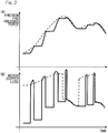
- diagram (A) shows an example of an operation of varying the pressing force of the friction pad 6 (vertical axis) over time (horizontal axis) in the electric brake device
- diagram (B) shows transition of motor copper loss in this case (vertical axis) over time (horizontal axis).
- the dotted line shows the case of following the braking force command value without any error as in the conventional art
- the solid line shows the case of limiting the time during which the positive efficiency operation shown by the straight line (1) in Fig. 5 is performed as in the present embodiment.
- the motor copper loss decreases as shown by the solid line in diagram (B) of Fig. 2 by decreasing the motor torque such that the motor torque does not fall below the reverse efficiency line shown by the straight line (2) in Fig. 5 .
- the motor torque that does not fall below the reverse efficiency line can be obtained, for example, by analyzing or measuring in advance a correlation between the torque and the pressing force of the conversion mechanism 9. Controlling of decreasing the motor torque such that the motor torque does not fall below the reverse efficiency line can be achieved by setting the motor torque obtained thus in the positive efficiency operation limiter 22.
- the light braking-time non-execution section 25 executes positive efficiency operation limitation by the positive efficiency operation limiter 22 only when the braking force command value, which is a requested braking force, is equal to or greater than a predetermined value. It is thought that the positive efficiency operation limitation becomes more effective as the braking force, that is, the pad pressing force, increases, and, in general, influence on deterioration of the feeling of the operator becomes smaller as deceleration of the vehicle increases. Thus, both desired power consumption and desired feeling can be achieved by executing the positive efficiency operation limitation only when the braking force command value is equal to or greater than the predetermined value.
- the braking force-corresponding limitation degree change section 23 may be configured to decrease the ratio of the time for increasing the braking force relative to the sum as the braking force increases. Accordingly, both desired power consumption and desired feeling can be achieved further favorably.
- the motor temperature-corresponding execution section 26 monitors the motor temperature of the electric brake device, and executes the positive efficiency operation limitation by the positive efficiency operation limiter 22 when the motor temperature becomes equal to or higher than a predetermined value. That is, feeling is prioritized when the temperature of the motor is low, and power consumption is reduced as the temperature increases, thereby suppressing motor heat generation. In general, in the case where motor copper loss is a problem as power consumption of the vehicle, it is thought that corresponding loss occurs in the motor to generate heat. Thus, also in this method, both desired power consumption and desired feeling can be achieved.
- the temperature-corresponding limitation degree change section 24 when configured to decrease the ratio of the time for increasing the braking force as the motor temperature increases, both desired power consumption and desired feeling can be achieved further favorably.
- the temperature-corresponding limitation degree change section 24 decreases the ratio of the time for increasing the braking force, in accordance with increase of the motor temperature by using a LUT implemented by software or hardware and a predetermined transform function contained in a library of software, or hardware equivalent to those, etc.
- the vehicle speed-corresponding execution section 27 executes the positive efficiency operation limitation by the positive efficiency operation limiter 22 only when the speed of the vehicle is equal to or lower than a predetermined value. In the case of performing such control, particularly when the vehicle has stopped or is at stoppage, the above feeling deterioration does not occur. Any one of the light braking-time non-execution section 25, the motor temperature-corresponding execution section 26, and the vehicle speed-corresponding execution section 27 may be selectively used, or any two of them may be used in combination, or all of them may be used in combination.
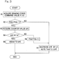
- FIG. 3 An example of a basic process performed by the positive efficiency operation limiter 22 will be described with reference to Fig. 3 .
- the example in Fig. 3 is an example in which limitation is performed on the basis of the braking force command value.
- a braking force command value Ft(k) is acquired from the braking force command section 12 (step R1) and is compared with a braking force command value Ft(k-1) acquired last time (step R2).
- a value cnt of a counter CN Fig. 1
- the counter value cnt is defined to satisfy 0 ⁇ cnt, and is set to 0 when the counter value cnt becomes negative as a result of the decrease by ⁇ in the process in step R7.
- the counter is provided in the positive efficiency operation limiter 22 in order to determine the ratio in the positive efficiency operation limitation.
- the value ⁇ and a later-described value ⁇ are arbitrarily set for determining the ratio in the positive efficiency operation limitation. As an example, the value ⁇ is set to 4, and the value ⁇ is set to 1. These values ⁇ and ⁇ may be varied by an operation of appropriate input means or the like connected to the brake controller 2 or the ECU 11.
- step R7 After the counter decrease in step R7, the process is ended, that is, a return is made.
- a braking force command value Ft(k) is acquired (step R1) and is compared with a braking force command value Ft(k-1) (step R2).
- the process in step R7 is performed, then a return is made, and a braking force command value Ft(k) is acquired again (step R1).
- the value cnt of the counter is acquired (step R3) and is compared to a set value x for determination (step R4).
- ⁇ is added to the counter value cnt, and a return is made.
- a braking force command value Ft(k) is acquired (step R1) and is compared to a braking force command value Ft(k-1) (step R2).
- step R6 the braking force command value Ft(k) is changed to the braking force command value Ft(k-1) acquired last time, and control of a command to output a motor current by the basic control section 21 is caused to be performed. That is, even when the braking force command value Ft(k) has increased, the command value of the motor current to be outputted from the basic control section 21 is maintained at a value that is equal to the last value. While the limitation by the positive efficiency operation limiter 22 is not performed, the basic control section 21 outputs the command value of the motor current in accordance with the braking force command value Ft(k) outputted from the braking force command section 12.
- step R7 the counter value cnt is decreased by ⁇ , and a return is made.
- ⁇ 1
- the present counter value cnt is changed from the above 4 to 3.
- a braking force command value Ft(k) is acquired (step R1) and is compared to a braking force command value Ft(k-1) (step R2).
- control in which the command value of the motor current to be sent from the basic control section 21 is maintained constant is performed.
- the counter value cnt is decreased by ⁇ each time the process of maintaining the braking force command value Ft(k) as the braking force command value Ft(k-1) acquired last time (step R6) is performed.
- the counter value cnt satisfies cnt ⁇ x as a result of the determination in step R4, and the process proceeds to the "yes" branch, so that the process of maintaining the braking force command value Ft(k) as the braking force command value Ft(k-1) acquired last time in step R6, that is, the positive efficiency operation limitation, is not performed.
- the basic control section 21 outputs a command of the motor current corresponding to the braking force command value Ft(k) outputted from the braking force command section 12.
- step R6 the process of maintaining the braking force command value Ft(k) as the braking force command value Ft(k-1) acquired last time (step R6) is performed.
- step R6 the braking force command value Ft(k) to be outputted from the braking force command section 12 is maintained, that is, positive efficiency operation is performed.
- a control with the ratio in the positive efficiency operation limitation being determined can be performed. For example, when the value ⁇ is set to 4 and the value ⁇ is set to 1, the ratio of a time for performing positive efficiency operation relative to the full operation time is limited to 20% or less. Even when ⁇ and ⁇ are fixed, the ratio changes depending on the value of the threshold x, and the ratio varies also depending on the state of the counter. At this time, for example, by setting ⁇ to a common multiple of ⁇ (or vice versa) and satisfying 0 ⁇ x ⁇ ⁇ , the ratio between ⁇ and ⁇ obviously becomes roughly the positive efficiency operation limitation ratio and thus becomes a parameter that is easy to understand.
- an increase/decrease range of cnt may be fixed as 1, and a flow of control may be provided in which an authority to shift to the flow corresponding to "no" branch in step R4 in Fig. 3 and to clear cnt in this flow corresponding to this "no" branch when the condition of cnt > ⁇ is satisfied, is obtained, and an authority to shift to the flow corresponding to "yes" branch in step R4 in Fig. 3 when the condition of cnt > ⁇ is satisfied, is obtained.
- the relation between ⁇ and ⁇ obviously become equal to the positive efficiency operation limitation ratio.
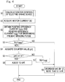
- the example in Fig. 4 is an example in which limitation is performed on the basis of the motor current.
- the basic control section 21 of the electric brake device calculates a motor current I(k) corresponding to the braking force command value sent from the braking force command section 12, and outputs the motor current I(k) to the power circuit section 14 (step S0).
- the positive efficiency operation limiter 22 acquires the value of the calculated motor current I(k) (step S1), and obtains a positive efficiency current I pos and a reverse efficiency current I neg required for maintaining the present braking force, by using a calculation formula or a table (not shown) set in the positive efficiency operation limiter 22 (step S2).
- the table or the calculation formula is created in advance by simulation or an experiment.
- step S2 The motor current I(k) calculated as described above and the required positive efficiency current I pos are compared to each other (step S2).
- a value cnt of a counter (not shown) is changed to a value obtained by decreasing the value cnt by a predetermined value ⁇ (step S8).
- the counter value cnt is defined to satisfy 0 ⁇ cnt, and is set to 0 when the counter value cnt becomes negative as a result of the decrease by ⁇ in the process in step S8.
- the counter is provided in the positive efficiency operation limiter 22 in order to determine the ratio in the positive efficiency operation limitation.
- the value ⁇ and a later-described value ⁇ are arbitrarily set for determining the ratio in the positive efficiency operation limitation. As an example, the value ⁇ is set to 4, and the value ⁇ is set to 1. These values ⁇ and ⁇ may be varied by an operation of appropriate input means provided to the brake controller 2 or the ECU 11, etc.
- step S8 After the counter decrease in step S8, the process is ended, that is, a return is made.
- step S0 a motor current I(k) is calculated (step S0)
- step S1 the motor current I(k) is acquired (step S1)
- step S2 a positive efficiency current I pos and a reverse efficiency current I neg required for maintaining the braking force are calculated (step S2)
- step S3 the motor current I(k) and the positive efficiency current I pos are compared to each other.
- step S4 When the motor current I(k) is larger than the positive efficiency current I pos as a result of the determination in step S3 ("yes" in step S3), the value cnt of the counter is acquired (step S4) and is compared to a set value x for determination (step S5).
- ⁇ is added to the counter value cnt, and a return is made.
- a motor current I(k) is calculated (step S0), the motor current I(k) is acquired (step S1), a positive efficiency current I pos and a reverse efficiency current I neg required for maintaining the braking force are calculated (step S2), and the motor current I(k) and the positive efficiency current I pos are compared to each other (step S3).
- step S7 the motor current I(k) is changed to the reverse efficiency current I neg , and the motor current to be outputted by the basic control section 21 is set to the reverse efficiency current I neg . That is, even when the motor current I(k) has increased, the command value of the motor current to be outputted from the basic control section 21 is set to the reverse efficiency current I neg . While the limitation by the positive efficiency operation limiter 22 is not performed, the basic control section 21 outputs the motor current I(k) in accordance with the braking force command value Ft(k) outputted from the braking force command section 12.
- step S8 the counter value cnt is decreased by ⁇ , and a return is made.
- ⁇ 1
- the present counter value cnt is changed from the above 4 to 3.
- step S2 a motor current I(k) and a positive efficiency current I pos are compared to each other (step S2).
- the counter value cnt is decreased by ⁇ (step S8) each time the process of decreasing the motor current I(k) to the reverse efficiency current I neg (step S7) is performed.
- the counter value cnt satisfies the condition of cnt ⁇ x as a result of the determination in step S5, and the process proceeds to the "yes" branch, so that the process of decreasing the motor current I(k) in step S7, that is, the positive efficiency operation limitation, is not performed.
- the basic control section 21 outputs a command of the motor current I(k) corresponding to the braking force command value Ft(k) outputted from the braking force command section 12.
- step S7 the process proceeds to the "no" branch again as a result of the determination with the set value x in step S5, and the process of decreasing the motor current I(k) to the reverse efficiency current I neg (step S7) is performed.
- step S5 the motor current I(k) corresponding to the braking force command value Ft(k) outputted from the braking force command section 12 is maintained, that is, positive efficiency operation is performed.
- the current is decreased by using the frictional force to maintain the pressing force of the conversion mechanism 9, thereby allowing the power consumption to be reduced by reducing loss caused by conductor resistance.
- motor heat generation is suppressed by a reduction in the motor current, so that improvement of the reliability and size reduction of the motor are enabled.
Landscapes
- Engineering & Computer Science (AREA)
- Mechanical Engineering (AREA)
- General Engineering & Computer Science (AREA)
- Transportation (AREA)
- Braking Systems And Boosters (AREA)
- Regulating Braking Force (AREA)
- Braking Arrangements (AREA)
- Electric Propulsion And Braking For Vehicles (AREA)
Priority Applications (1)
| Application Number | Priority Date | Filing Date | Title |
|---|---|---|---|
| EP18208454.1A EP3466779B1 (de) | 2014-05-14 | 2015-05-07 | Elektrische bremsvorrichtung |
Applications Claiming Priority (2)
| Application Number | Priority Date | Filing Date | Title |
|---|---|---|---|
| JP2014100290A JP6306426B2 (ja) | 2014-05-14 | 2014-05-14 | 電動ブレーキ装置 |
| PCT/JP2015/063181 WO2015174314A1 (ja) | 2014-05-14 | 2015-05-07 | 電動ブレーキ装置 |
Related Child Applications (2)
| Application Number | Title | Priority Date | Filing Date |
|---|---|---|---|
| EP18208454.1A Division EP3466779B1 (de) | 2014-05-14 | 2015-05-07 | Elektrische bremsvorrichtung |
| EP18208454.1A Division-Into EP3466779B1 (de) | 2014-05-14 | 2015-05-07 | Elektrische bremsvorrichtung |
Publications (3)
| Publication Number | Publication Date |
|---|---|
| EP3144192A1 true EP3144192A1 (de) | 2017-03-22 |
| EP3144192A4 EP3144192A4 (de) | 2017-12-27 |
| EP3144192B1 EP3144192B1 (de) | 2019-01-02 |
Family
ID=54479855
Family Applications (2)
| Application Number | Title | Priority Date | Filing Date |
|---|---|---|---|
| EP15792738.5A Active EP3144192B1 (de) | 2014-05-14 | 2015-05-07 | Elektrische bremsvorrichtung |
| EP18208454.1A Active EP3466779B1 (de) | 2014-05-14 | 2015-05-07 | Elektrische bremsvorrichtung |
Family Applications After (1)
| Application Number | Title | Priority Date | Filing Date |
|---|---|---|---|
| EP18208454.1A Active EP3466779B1 (de) | 2014-05-14 | 2015-05-07 | Elektrische bremsvorrichtung |
Country Status (5)
| Country | Link |
|---|---|
| US (1) | US11420604B2 (de) |
| EP (2) | EP3144192B1 (de) |
| JP (1) | JP6306426B2 (de) |
| CN (2) | CN106414191B (de) |
| WO (1) | WO2015174314A1 (de) |
Cited By (1)
| Publication number | Priority date | Publication date | Assignee | Title |
|---|---|---|---|---|
| EP3521116A4 (de) * | 2016-09-28 | 2020-04-08 | NTN Corporation | Elektrische bremsvorrichtung |
Families Citing this family (11)
| Publication number | Priority date | Publication date | Assignee | Title |
|---|---|---|---|---|
| JP6575421B2 (ja) * | 2016-04-08 | 2019-09-18 | 株式会社アドヴィックス | 車両の制動制御装置 |
| JP6752668B2 (ja) * | 2016-09-28 | 2020-09-09 | Ntn株式会社 | 電動ブレーキ装置 |
| JP2019043228A (ja) * | 2017-08-30 | 2019-03-22 | 株式会社シマノ | 電動ブレーキシステム |
| JP2019043227A (ja) * | 2017-08-30 | 2019-03-22 | 株式会社シマノ | ブレーキ装置および電動ブレーキシステム |
| CN110758366B (zh) * | 2019-10-31 | 2021-12-10 | 上海拿森汽车电子有限公司 | 一种电子助力刹车系统的扭矩控制方法及装置 |
| JP7435503B2 (ja) * | 2021-02-25 | 2024-02-21 | 株式会社デンソー | 車両用制動装置 |
| JP7552565B2 (ja) | 2021-12-08 | 2024-09-18 | 株式会社デンソー | 車両用制動装置 |
| JP7797988B2 (ja) * | 2022-09-01 | 2026-01-14 | 株式会社デンソー | 車両用制動装置 |
| KR20240075002A (ko) * | 2022-11-16 | 2024-05-29 | 현대자동차주식회사 | 모터 발열 최소화 장치 및 최소화 방법 |
| JP2025117652A (ja) * | 2024-01-31 | 2025-08-13 | 株式会社アドヴィックス | 電動制動装置 |
| US20260054710A1 (en) * | 2024-08-20 | 2026-02-26 | Ford Global Technologies, Llc | Methods and apparatus to estimate brake pad wear |
Family Cites Families (21)
| Publication number | Priority date | Publication date | Assignee | Title |
|---|---|---|---|---|
| JPS63266228A (ja) * | 1987-04-17 | 1988-11-02 | Honda Motor Co Ltd | ブレ−キ装置 |
| JPH0664518A (ja) | 1992-08-19 | 1994-03-08 | Mitsubishi Motors Corp | アンチスキッドブレーキング方法 |
| JP3166401B2 (ja) | 1993-05-17 | 2001-05-14 | 日産自動車株式会社 | 電動ブレーキ用アクチュエータ |
| JP3893753B2 (ja) | 1997-12-16 | 2007-03-14 | トヨタ自動車株式会社 | 電動式ブレーキ装置 |
| DE19841170C1 (de) * | 1998-09-09 | 2000-02-24 | Continental Ag | Verfahren zur sparsamen Nutzung der von einem elektrisch betätigbaren Bremsaktuator benötigten elektrischen Energie |
| JP3456949B2 (ja) | 2000-06-19 | 2003-10-14 | 株式会社エスティック | ネジ締め装置の制御方法および装置 |
| JP3927357B2 (ja) * | 2000-08-29 | 2007-06-06 | トヨタ自動車株式会社 | 車両用ブレーキ装置 |
| JP4590709B2 (ja) * | 2000-09-28 | 2010-12-01 | 株式会社デンソー | 車両用ブレーキ装置 |
| JP2003083373A (ja) * | 2001-09-07 | 2003-03-19 | Akebono Brake Ind Co Ltd | 電動ブレーキ制御方法 |
| JP2004122838A (ja) * | 2002-08-07 | 2004-04-22 | Asmo Co Ltd | 電動駐車ブレーキ装置及び電動駐車ブレーキ装置の制御方法 |
| US6851765B1 (en) * | 2003-08-28 | 2005-02-08 | Delphi Technologies, Inc. | System and method for controlling a brake motor |
| JP4898123B2 (ja) | 2005-01-13 | 2012-03-14 | Ntn株式会社 | 電動式直動アクチュエータおよび電動式ブレーキ装置 |
| JP4339275B2 (ja) | 2005-05-12 | 2009-10-07 | 株式会社エスティック | インパクト式のネジ締め装置の制御方法および装置 |
| JP4887738B2 (ja) * | 2005-11-01 | 2012-02-29 | トヨタ自動車株式会社 | モータ駆動装置 |
| JP2007143311A (ja) * | 2005-11-18 | 2007-06-07 | Yaskawa Electric Corp | モータ制御装置および電磁ブレーキ付モータ |
| JP2008095909A (ja) * | 2006-10-16 | 2008-04-24 | Hitachi Ltd | 電動ブレーキ装置 |
| JP4956800B2 (ja) * | 2009-06-05 | 2012-06-20 | 日産自動車株式会社 | 車輪独立駆動式電気自動車の駆動力制御装置 |
| KR20110124818A (ko) | 2010-05-12 | 2011-11-18 | 주식회사 만도 | 전동식 디스크브레이크 |
| JP5624531B2 (ja) * | 2011-09-29 | 2014-11-12 | 株式会社アドヴィックス | 車両の制動制御装置 |
| JP5835576B2 (ja) * | 2011-12-27 | 2015-12-24 | 株式会社アドヴィックス | 車両の制動制御装置 |
| JP6397694B2 (ja) * | 2014-08-25 | 2018-09-26 | 日立オートモティブシステムズ株式会社 | ブレーキ装置 |
-
2014
- 2014-05-14 JP JP2014100290A patent/JP6306426B2/ja active Active
-
2015
- 2015-05-07 CN CN201580024693.0A patent/CN106414191B/zh active Active
- 2015-05-07 EP EP15792738.5A patent/EP3144192B1/de active Active
- 2015-05-07 CN CN201910007043.5A patent/CN110053596B/zh active Active
- 2015-05-07 EP EP18208454.1A patent/EP3466779B1/de active Active
- 2015-05-07 WO PCT/JP2015/063181 patent/WO2015174314A1/ja not_active Ceased
-
2016
- 2016-11-03 US US15/342,611 patent/US11420604B2/en active Active
Cited By (2)
| Publication number | Priority date | Publication date | Assignee | Title |
|---|---|---|---|---|
| EP3521116A4 (de) * | 2016-09-28 | 2020-04-08 | NTN Corporation | Elektrische bremsvorrichtung |
| US11001246B2 (en) | 2016-09-28 | 2021-05-11 | Ntn Corporation | Electric brake device |
Also Published As
| Publication number | Publication date |
|---|---|
| EP3466779B1 (de) | 2020-03-11 |
| US20170072931A1 (en) | 2017-03-16 |
| CN106414191B (zh) | 2019-02-15 |
| EP3144192B1 (de) | 2019-01-02 |
| US11420604B2 (en) | 2022-08-23 |
| EP3144192A4 (de) | 2017-12-27 |
| CN110053596A (zh) | 2019-07-26 |
| CN106414191A (zh) | 2017-02-15 |
| JP2015217697A (ja) | 2015-12-07 |
| WO2015174314A1 (ja) | 2015-11-19 |
| CN110053596B (zh) | 2021-08-10 |
| EP3466779A1 (de) | 2019-04-10 |
| JP6306426B2 (ja) | 2018-04-04 |
Similar Documents
| Publication | Publication Date | Title |
|---|---|---|
| US11420604B2 (en) | Electric brake device | |
| US10384659B2 (en) | Electric brake device | |
| JP6752668B2 (ja) | 電動ブレーキ装置 | |
| EP3124345A1 (de) | Elektrische bremsvorrichtung | |
| WO2015041108A1 (ja) | 電気自動車のスリップ制御装置 | |
| US7622879B2 (en) | Thermal protection apparatus and method for hybrid vehicles | |
| EP3208483B1 (de) | Elektrische bremsvorrichtung | |
| WO2016181898A1 (ja) | 電動モータ装置および電動式直動アクチュエータ | |
| JP5940290B2 (ja) | 電気車制御装置 | |
| JP6505896B2 (ja) | 電動ブレーキ装置 | |
| TW201622337A (zh) | 馬達控制裝置 | |
| JP6466261B2 (ja) | 電動ブレーキ装置 | |
| JP2016220338A (ja) | 電動ブレーキ装置 | |
| KR102337338B1 (ko) | 전자식 브레이크의 모터 제어 방법 | |
| JP2018114975A5 (de) | ||
| JP7116551B2 (ja) | 電動ブレーキ装置および電動ブレーキシステム | |
| WO2015146906A1 (ja) | 電動ブレーキ装置 | |
| US10972042B2 (en) | Electric-motor control apparatus | |
| JP2021035819A (ja) | 転舵装置 | |
| JP2017070203A (ja) | 少なくとも1つの交流モータを備えている装置 | |
| CN119010664A (zh) | 驱动控制装置 |
Legal Events
| Date | Code | Title | Description |
|---|---|---|---|
| STAA | Information on the status of an ep patent application or granted ep patent |
Free format text: STATUS: THE INTERNATIONAL PUBLICATION HAS BEEN MADE |
|
| PUAI | Public reference made under article 153(3) epc to a published international application that has entered the european phase |
Free format text: ORIGINAL CODE: 0009012 |
|
| STAA | Information on the status of an ep patent application or granted ep patent |
Free format text: STATUS: REQUEST FOR EXAMINATION WAS MADE |
|
| 17P | Request for examination filed |
Effective date: 20161104 |
|
| AK | Designated contracting states |
Kind code of ref document: A1 Designated state(s): AL AT BE BG CH CY CZ DE DK EE ES FI FR GB GR HR HU IE IS IT LI LT LU LV MC MK MT NL NO PL PT RO RS SE SI SK SM TR |
|
| AX | Request for extension of the european patent |
Extension state: BA ME |
|
| DAV | Request for validation of the european patent (deleted) | ||
| DAX | Request for extension of the european patent (deleted) | ||
| A4 | Supplementary search report drawn up and despatched |
Effective date: 20171127 |
|
| RIC1 | Information provided on ipc code assigned before grant |
Ipc: F16D 65/18 20060101ALI20171121BHEP Ipc: B60T 13/74 20060101ALI20171121BHEP Ipc: F16D 66/00 20060101ALI20171121BHEP Ipc: F16D 121/24 20120101ALI20171121BHEP Ipc: B60T 8/17 20060101ALI20171121BHEP Ipc: B60T 8/00 20060101AFI20171121BHEP |
|
| GRAP | Despatch of communication of intention to grant a patent |
Free format text: ORIGINAL CODE: EPIDOSNIGR1 |
|
| STAA | Information on the status of an ep patent application or granted ep patent |
Free format text: STATUS: GRANT OF PATENT IS INTENDED |
|
| INTG | Intention to grant announced |
Effective date: 20180801 |
|
| GRAS | Grant fee paid |
Free format text: ORIGINAL CODE: EPIDOSNIGR3 |
|
| GRAA | (expected) grant |
Free format text: ORIGINAL CODE: 0009210 |
|
| STAA | Information on the status of an ep patent application or granted ep patent |
Free format text: STATUS: THE PATENT HAS BEEN GRANTED |
|
| AK | Designated contracting states |
Kind code of ref document: B1 Designated state(s): AL AT BE BG CH CY CZ DE DK EE ES FI FR GB GR HR HU IE IS IT LI LT LU LV MC MK MT NL NO PL PT RO RS SE SI SK SM TR |
|
| REG | Reference to a national code |
Ref country code: GB Ref legal event code: FG4D |
|
| REG | Reference to a national code |
Ref country code: CH Ref legal event code: EP Ref country code: AT Ref legal event code: REF Ref document number: 1083951 Country of ref document: AT Kind code of ref document: T Effective date: 20190115 |
|
| REG | Reference to a national code |
Ref country code: IE Ref legal event code: FG4D |
|
| REG | Reference to a national code |
Ref country code: DE Ref legal event code: R096 Ref document number: 602015022903 Country of ref document: DE |
|
| REG | Reference to a national code |
Ref country code: NL Ref legal event code: MP Effective date: 20190102 |
|
| REG | Reference to a national code |
Ref country code: LT Ref legal event code: MG4D |
|
| REG | Reference to a national code |
Ref country code: AT Ref legal event code: MK05 Ref document number: 1083951 Country of ref document: AT Kind code of ref document: T Effective date: 20190102 |
|
| PG25 | Lapsed in a contracting state [announced via postgrant information from national office to epo] |
Ref country code: NL Free format text: LAPSE BECAUSE OF FAILURE TO SUBMIT A TRANSLATION OF THE DESCRIPTION OR TO PAY THE FEE WITHIN THE PRESCRIBED TIME-LIMIT Effective date: 20190102 |
|
| PG25 | Lapsed in a contracting state [announced via postgrant information from national office to epo] |
Ref country code: PT Free format text: LAPSE BECAUSE OF FAILURE TO SUBMIT A TRANSLATION OF THE DESCRIPTION OR TO PAY THE FEE WITHIN THE PRESCRIBED TIME-LIMIT Effective date: 20190502 Ref country code: ES Free format text: LAPSE BECAUSE OF FAILURE TO SUBMIT A TRANSLATION OF THE DESCRIPTION OR TO PAY THE FEE WITHIN THE PRESCRIBED TIME-LIMIT Effective date: 20190102 Ref country code: SE Free format text: LAPSE BECAUSE OF FAILURE TO SUBMIT A TRANSLATION OF THE DESCRIPTION OR TO PAY THE FEE WITHIN THE PRESCRIBED TIME-LIMIT Effective date: 20190102 Ref country code: FI Free format text: LAPSE BECAUSE OF FAILURE TO SUBMIT A TRANSLATION OF THE DESCRIPTION OR TO PAY THE FEE WITHIN THE PRESCRIBED TIME-LIMIT Effective date: 20190102 Ref country code: NO Free format text: LAPSE BECAUSE OF FAILURE TO SUBMIT A TRANSLATION OF THE DESCRIPTION OR TO PAY THE FEE WITHIN THE PRESCRIBED TIME-LIMIT Effective date: 20190402 Ref country code: LT Free format text: LAPSE BECAUSE OF FAILURE TO SUBMIT A TRANSLATION OF THE DESCRIPTION OR TO PAY THE FEE WITHIN THE PRESCRIBED TIME-LIMIT Effective date: 20190102 Ref country code: PL Free format text: LAPSE BECAUSE OF FAILURE TO SUBMIT A TRANSLATION OF THE DESCRIPTION OR TO PAY THE FEE WITHIN THE PRESCRIBED TIME-LIMIT Effective date: 20190102 |
|
| PG25 | Lapsed in a contracting state [announced via postgrant information from national office to epo] |
Ref country code: BG Free format text: LAPSE BECAUSE OF FAILURE TO SUBMIT A TRANSLATION OF THE DESCRIPTION OR TO PAY THE FEE WITHIN THE PRESCRIBED TIME-LIMIT Effective date: 20190402 Ref country code: IS Free format text: LAPSE BECAUSE OF FAILURE TO SUBMIT A TRANSLATION OF THE DESCRIPTION OR TO PAY THE FEE WITHIN THE PRESCRIBED TIME-LIMIT Effective date: 20190502 Ref country code: GR Free format text: LAPSE BECAUSE OF FAILURE TO SUBMIT A TRANSLATION OF THE DESCRIPTION OR TO PAY THE FEE WITHIN THE PRESCRIBED TIME-LIMIT Effective date: 20190403 Ref country code: HR Free format text: LAPSE BECAUSE OF FAILURE TO SUBMIT A TRANSLATION OF THE DESCRIPTION OR TO PAY THE FEE WITHIN THE PRESCRIBED TIME-LIMIT Effective date: 20190102 Ref country code: LV Free format text: LAPSE BECAUSE OF FAILURE TO SUBMIT A TRANSLATION OF THE DESCRIPTION OR TO PAY THE FEE WITHIN THE PRESCRIBED TIME-LIMIT Effective date: 20190102 Ref country code: RS Free format text: LAPSE BECAUSE OF FAILURE TO SUBMIT A TRANSLATION OF THE DESCRIPTION OR TO PAY THE FEE WITHIN THE PRESCRIBED TIME-LIMIT Effective date: 20190102 |
|
| REG | Reference to a national code |
Ref country code: DE Ref legal event code: R097 Ref document number: 602015022903 Country of ref document: DE |
|
| PG25 | Lapsed in a contracting state [announced via postgrant information from national office to epo] |
Ref country code: IT Free format text: LAPSE BECAUSE OF FAILURE TO SUBMIT A TRANSLATION OF THE DESCRIPTION OR TO PAY THE FEE WITHIN THE PRESCRIBED TIME-LIMIT Effective date: 20190102 Ref country code: RO Free format text: LAPSE BECAUSE OF FAILURE TO SUBMIT A TRANSLATION OF THE DESCRIPTION OR TO PAY THE FEE WITHIN THE PRESCRIBED TIME-LIMIT Effective date: 20190102 Ref country code: CZ Free format text: LAPSE BECAUSE OF FAILURE TO SUBMIT A TRANSLATION OF THE DESCRIPTION OR TO PAY THE FEE WITHIN THE PRESCRIBED TIME-LIMIT Effective date: 20190102 Ref country code: DK Free format text: LAPSE BECAUSE OF FAILURE TO SUBMIT A TRANSLATION OF THE DESCRIPTION OR TO PAY THE FEE WITHIN THE PRESCRIBED TIME-LIMIT Effective date: 20190102 Ref country code: AT Free format text: LAPSE BECAUSE OF FAILURE TO SUBMIT A TRANSLATION OF THE DESCRIPTION OR TO PAY THE FEE WITHIN THE PRESCRIBED TIME-LIMIT Effective date: 20190102 Ref country code: EE Free format text: LAPSE BECAUSE OF FAILURE TO SUBMIT A TRANSLATION OF THE DESCRIPTION OR TO PAY THE FEE WITHIN THE PRESCRIBED TIME-LIMIT Effective date: 20190102 Ref country code: AL Free format text: LAPSE BECAUSE OF FAILURE TO SUBMIT A TRANSLATION OF THE DESCRIPTION OR TO PAY THE FEE WITHIN THE PRESCRIBED TIME-LIMIT Effective date: 20190102 Ref country code: SK Free format text: LAPSE BECAUSE OF FAILURE TO SUBMIT A TRANSLATION OF THE DESCRIPTION OR TO PAY THE FEE WITHIN THE PRESCRIBED TIME-LIMIT Effective date: 20190102 |
|
| PLBE | No opposition filed within time limit |
Free format text: ORIGINAL CODE: 0009261 |
|
| STAA | Information on the status of an ep patent application or granted ep patent |
Free format text: STATUS: NO OPPOSITION FILED WITHIN TIME LIMIT |
|
| PG25 | Lapsed in a contracting state [announced via postgrant information from national office to epo] |
Ref country code: SM Free format text: LAPSE BECAUSE OF FAILURE TO SUBMIT A TRANSLATION OF THE DESCRIPTION OR TO PAY THE FEE WITHIN THE PRESCRIBED TIME-LIMIT Effective date: 20190102 |
|
| 26N | No opposition filed |
Effective date: 20191003 |
|
| REG | Reference to a national code |
Ref country code: CH Ref legal event code: PL |
|
| GBPC | Gb: european patent ceased through non-payment of renewal fee |
Effective date: 20190507 |
|
| PG25 | Lapsed in a contracting state [announced via postgrant information from national office to epo] |
Ref country code: MC Free format text: LAPSE BECAUSE OF FAILURE TO SUBMIT A TRANSLATION OF THE DESCRIPTION OR TO PAY THE FEE WITHIN THE PRESCRIBED TIME-LIMIT Effective date: 20190102 Ref country code: CH Free format text: LAPSE BECAUSE OF NON-PAYMENT OF DUE FEES Effective date: 20190531 Ref country code: LI Free format text: LAPSE BECAUSE OF NON-PAYMENT OF DUE FEES Effective date: 20190531 |
|
| REG | Reference to a national code |
Ref country code: BE Ref legal event code: MM Effective date: 20190531 |
|
| PG25 | Lapsed in a contracting state [announced via postgrant information from national office to epo] |
Ref country code: SI Free format text: LAPSE BECAUSE OF FAILURE TO SUBMIT A TRANSLATION OF THE DESCRIPTION OR TO PAY THE FEE WITHIN THE PRESCRIBED TIME-LIMIT Effective date: 20190102 Ref country code: LU Free format text: LAPSE BECAUSE OF NON-PAYMENT OF DUE FEES Effective date: 20190507 |
|
| PG25 | Lapsed in a contracting state [announced via postgrant information from national office to epo] |
Ref country code: TR Free format text: LAPSE BECAUSE OF FAILURE TO SUBMIT A TRANSLATION OF THE DESCRIPTION OR TO PAY THE FEE WITHIN THE PRESCRIBED TIME-LIMIT Effective date: 20190102 |
|
| PG25 | Lapsed in a contracting state [announced via postgrant information from national office to epo] |
Ref country code: GB Free format text: LAPSE BECAUSE OF NON-PAYMENT OF DUE FEES Effective date: 20190507 Ref country code: IE Free format text: LAPSE BECAUSE OF NON-PAYMENT OF DUE FEES Effective date: 20190507 |
|
| PG25 | Lapsed in a contracting state [announced via postgrant information from national office to epo] |
Ref country code: BE Free format text: LAPSE BECAUSE OF NON-PAYMENT OF DUE FEES Effective date: 20190531 |
|
| PG25 | Lapsed in a contracting state [announced via postgrant information from national office to epo] |
Ref country code: CY Free format text: LAPSE BECAUSE OF FAILURE TO SUBMIT A TRANSLATION OF THE DESCRIPTION OR TO PAY THE FEE WITHIN THE PRESCRIBED TIME-LIMIT Effective date: 20190102 |
|
| PG25 | Lapsed in a contracting state [announced via postgrant information from national office to epo] |
Ref country code: MT Free format text: LAPSE BECAUSE OF FAILURE TO SUBMIT A TRANSLATION OF THE DESCRIPTION OR TO PAY THE FEE WITHIN THE PRESCRIBED TIME-LIMIT Effective date: 20190102 Ref country code: HU Free format text: LAPSE BECAUSE OF FAILURE TO SUBMIT A TRANSLATION OF THE DESCRIPTION OR TO PAY THE FEE WITHIN THE PRESCRIBED TIME-LIMIT; INVALID AB INITIO Effective date: 20150507 |
|
| PG25 | Lapsed in a contracting state [announced via postgrant information from national office to epo] |
Ref country code: MK Free format text: LAPSE BECAUSE OF FAILURE TO SUBMIT A TRANSLATION OF THE DESCRIPTION OR TO PAY THE FEE WITHIN THE PRESCRIBED TIME-LIMIT Effective date: 20190102 |
|
| REG | Reference to a national code |
Ref country code: FR Ref legal event code: PLFP Year of fee payment: 9 |
|
| PGFP | Annual fee paid to national office [announced via postgrant information from national office to epo] |
Ref country code: DE Payment date: 20250402 Year of fee payment: 11 |
|
| PGFP | Annual fee paid to national office [announced via postgrant information from national office to epo] |
Ref country code: FR Payment date: 20250401 Year of fee payment: 11 |