EP3141663B1 - Procédé d'affichage d'un angle mort d'une machine de construction et appareil permettant de l'exécuter - Google Patents
Procédé d'affichage d'un angle mort d'une machine de construction et appareil permettant de l'exécuter Download PDFInfo
- Publication number
- EP3141663B1 EP3141663B1 EP16194111.7A EP16194111A EP3141663B1 EP 3141663 B1 EP3141663 B1 EP 3141663B1 EP 16194111 A EP16194111 A EP 16194111A EP 3141663 B1 EP3141663 B1 EP 3141663B1
- Authority
- EP
- European Patent Office
- Prior art keywords
- dead zone
- unit
- actual images
- cabin
- camera
- Prior art date
- Legal status (The legal status is an assumption and is not a legal conclusion. Google has not performed a legal analysis and makes no representation as to the accuracy of the status listed.)
- Active
Links
Images

Classifications
-
- E—FIXED CONSTRUCTIONS
- E02—HYDRAULIC ENGINEERING; FOUNDATIONS; SOIL SHIFTING
- E02F—DREDGING; SOIL-SHIFTING
- E02F9/00—Component parts of dredgers or soil-shifting machines, not restricted to one of the kinds covered by groups E02F3/00 - E02F7/00
- E02F9/26—Indicating devices
-
- E—FIXED CONSTRUCTIONS
- E02—HYDRAULIC ENGINEERING; FOUNDATIONS; SOIL SHIFTING
- E02F—DREDGING; SOIL-SHIFTING
- E02F9/00—Component parts of dredgers or soil-shifting machines, not restricted to one of the kinds covered by groups E02F3/00 - E02F7/00
- E02F9/24—Safety devices, e.g. for preventing overload
-
- E—FIXED CONSTRUCTIONS
- E02—HYDRAULIC ENGINEERING; FOUNDATIONS; SOIL SHIFTING
- E02F—DREDGING; SOIL-SHIFTING
- E02F9/00—Component parts of dredgers or soil-shifting machines, not restricted to one of the kinds covered by groups E02F3/00 - E02F7/00
- E02F9/26—Indicating devices
- E02F9/261—Surveying the work-site to be treated
-
- E—FIXED CONSTRUCTIONS
- E02—HYDRAULIC ENGINEERING; FOUNDATIONS; SOIL SHIFTING
- E02F—DREDGING; SOIL-SHIFTING
- E02F9/00—Component parts of dredgers or soil-shifting machines, not restricted to one of the kinds covered by groups E02F3/00 - E02F7/00
- E02F9/26—Indicating devices
- E02F9/264—Sensors and their calibration for indicating the position of the work tool
-
- G—PHYSICS
- G06—COMPUTING OR CALCULATING; COUNTING
- G06T—IMAGE DATA PROCESSING OR GENERATION, IN GENERAL
- G06T3/00—Geometric image transformations in the plane of the image
- G06T3/40—Scaling of whole images or parts thereof, e.g. expanding or contracting
- G06T3/4038—Image mosaicing, e.g. composing plane images from plane sub-images
-
- H—ELECTRICITY
- H04—ELECTRIC COMMUNICATION TECHNIQUE
- H04N—PICTORIAL COMMUNICATION, e.g. TELEVISION
- H04N23/00—Cameras or camera modules comprising electronic image sensors; Control thereof
- H04N23/60—Control of cameras or camera modules
- H04N23/698—Control of cameras or camera modules for achieving an enlarged field of view, e.g. panoramic image capture
-
- H—ELECTRICITY
- H04—ELECTRIC COMMUNICATION TECHNIQUE
- H04N—PICTORIAL COMMUNICATION, e.g. TELEVISION
- H04N23/00—Cameras or camera modules comprising electronic image sensors; Control thereof
- H04N23/90—Arrangement of cameras or camera modules, e.g. multiple cameras in TV studios or sports stadiums
-
- H—ELECTRICITY
- H04—ELECTRIC COMMUNICATION TECHNIQUE
- H04N—PICTORIAL COMMUNICATION, e.g. TELEVISION
- H04N5/00—Details of television systems
- H04N5/222—Studio circuitry; Studio devices; Studio equipment
- H04N5/262—Studio circuits, e.g. for mixing, switching-over, change of character of image, other special effects ; Cameras specially adapted for the electronic generation of special effects
- H04N5/265—Mixing
-
- H—ELECTRICITY
- H04—ELECTRIC COMMUNICATION TECHNIQUE
- H04N—PICTORIAL COMMUNICATION, e.g. TELEVISION
- H04N7/00—Television systems
- H04N7/18—Closed-circuit television [CCTV] systems, i.e. systems in which the video signal is not broadcast
- H04N7/181—Closed-circuit television [CCTV] systems, i.e. systems in which the video signal is not broadcast for receiving images from a plurality of remote sources
-
- B—PERFORMING OPERATIONS; TRANSPORTING
- B60—VEHICLES IN GENERAL
- B60R—VEHICLES, VEHICLE FITTINGS, OR VEHICLE PARTS, NOT OTHERWISE PROVIDED FOR
- B60R2300/00—Details of viewing arrangements using cameras and displays, specially adapted for use in a vehicle
- B60R2300/20—Details of viewing arrangements using cameras and displays, specially adapted for use in a vehicle characterised by the type of display used
- B60R2300/202—Details of viewing arrangements using cameras and displays, specially adapted for use in a vehicle characterised by the type of display used displaying a blind spot scene on the vehicle part responsible for the blind spot
-
- B—PERFORMING OPERATIONS; TRANSPORTING
- B60—VEHICLES IN GENERAL
- B60R—VEHICLES, VEHICLE FITTINGS, OR VEHICLE PARTS, NOT OTHERWISE PROVIDED FOR
- B60R2300/00—Details of viewing arrangements using cameras and displays, specially adapted for use in a vehicle
- B60R2300/80—Details of viewing arrangements using cameras and displays, specially adapted for use in a vehicle characterised by the intended use of the viewing arrangement
- B60R2300/802—Details of viewing arrangements using cameras and displays, specially adapted for use in a vehicle characterised by the intended use of the viewing arrangement for monitoring and displaying vehicle exterior blind spot views
-
- E—FIXED CONSTRUCTIONS
- E02—HYDRAULIC ENGINEERING; FOUNDATIONS; SOIL SHIFTING
- E02F—DREDGING; SOIL-SHIFTING
- E02F3/00—Dredgers; Soil-shifting machines
- E02F3/04—Dredgers; Soil-shifting machines mechanically-driven
- E02F3/28—Dredgers; Soil-shifting machines mechanically-driven with digging tools mounted on a dipper- or bucket-arm, i.e. there is either one arm or a pair of arms, e.g. dippers, buckets
Definitions
- Example embodiments relate to a method of displaying a dead zone of a construction machine and an apparatus for performing the same. More particularly, example embodiments relate to a method of displaying a dead zone formed by a boom of an excavator on a monitor of a cabin in the excavator, and an apparatus for performing the method.
- an excavator may include a lower driving body, an upper swing body pivotally connected to the lower driving body, a boom connected to the upper swing body, an arm connected to the boom, and an attachment selectively connected to the arm.
- the attachment may include a bucket, breaker, crusher, etc.
- a camera may be installed at the cabin. An image photographed by the camera may be displayed on a monitor in the cabin. The worker may rotate the boom with seeing the image on the monitor to prevent the generation of the negligent accident.
- a dead zone may be generated due to the rotated boom.
- the camera may not photograph the dead zone.
- an image of the dead zone may not be displayed on the monitor so that the worker in the cabin may not see the dead zone screened by the rotated boom.
- Prior art documents EP 2 631 374 Al and US 2013/182066 Al both disclose methods and devices for monitoring the dead (or hazard) zone around a construction machine by means of cameras mounted in the cabin but with views to the back and sides of the machine. The images are displayed to the machine operator as real-time moving images.
- the invention is defined by independent claim 1 which refers to a method of displaying a dead zone of a construction machine.
- a further aspect of the invention is defined in claim 2.
- the invention is further defined by independent claim 3 which refers to an apparatus for displaying a dead zone of a construction machine.
- a further aspect of the invention is defined in claim 4.
- FIGS. 1 to 8 represent non-limiting, example embodiments as described herein.
- first, second, third etc. may be used herein to describe various elements, components, regions, layers and/or sections, these elements, components, regions, layers and/or sections should not be limited by these terms. These terms are only used to distinguish one element, component, region, layer or section from another region, layer or section. Thus, a first element, component, region, layer or section discussed below could be termed a second element, component, region, layer or section without departing from the teachings of the present disclosure.
- spatially relative terms such as “beneath,” “below,” “lower,” “above,” “upper” and the like, may be used herein for ease of description to describe one element or feature's relationship to another element(s) or feature(s) as illustrated in the figures. It will be understood that the spatially relative terms are intended to encompass different orientations of the device in use or operation in addition to the orientation depicted in the figures. For example, if the device in the figures is turned over, elements described as “below” or “beneath” other elements or features would then be oriented “above” the other elements or features. Thus, the exemplary term “below” can encompass both an orientation of above and below. The device may be otherwise oriented (rotated 90 degrees or at other orientations) and the spatially relative descriptors used herein interpreted accordingly.
- Example embodiments are described herein with reference to cross-sectional illustrations that are schematic illustrations of idealized example embodiments (and intermediate structures). As such, variations from the shapes of the illustrations as a result, for example, of manufacturing techniques and/or tolerances, are to be expected. Thus, example embodiments should not be construed as limited to the particular shapes of regions illustrated herein but are to include deviations in shapes that result, for example, from manufacturing. For example, an implanted region illustrated as a rectangle will, typically, have rounded or curved features and/or a gradient of implant concentration at its edges rather than a binary change from implanted to non-implanted region.
- a buried region formed by implantation may result in some implantation in the region between the buried region and the surface through which the implantation takes place.
- the regions illustrated in the figures are schematic in nature and their shapes are not intended to illustrate the actual shape of a region of a device and are not intended to limit the scope of the present disclosure.
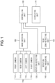
- FIG. 1 is a block diagram illustrating an apparatus for displaying a dead zone of a construction machine in accordance with example embodiments.
- an apparatus for displaying a dead zone of a construction machine may include a camera unit 110, an image-matching unit 120, a rotation-detecting unit 130, a rotation angle-measuring unit 140, a dead zone-detecting unit 150, a controlling unit 160 and a displaying unit 170.
- the construction machine may include a cabin and a working tool connected to the cabin.
- the construction machine may include an excavator.
- the excavator may include a lower driving body, an upper swing body pivotally connected to the lower driving body, a boom as the working tool connected to the upper swing body, an arm connected to the boom, and an attachment selectively connected to the arm.
- a worker in the cabin may not see a dead zone screened by the rotated boom.
- the dead zone may correspond to a zone positioned in front of a rotation direction of the boom and screened by the boom.
- the apparatus may be applied to other construction machines as well as the excavator.
- the camera unit 110 may be configured to obtain actual images with respect to omnidirectional views of the cabin in the excavator. That is, the camera unit 110 may photograph views shown from the cabin to obtain the actual images. The actual images photographed by the camera unit 110 may be displayed on the displaying unit 170. Thus, an around view monitoring (AVM) system may be applied to the excavator.
- AVM around view monitoring
- the camera unit 110 may include a front camera 112, a rear camera 114, a left camera 116 and a right camera 118.
- the front camera 112 may be installed at a front of the cabin to photograph front views of the cabin.
- the rear camera 114 may be installed at a rear of the cabin to photograph rear views of the cabin.
- the left camera 116 may be installed at a left side of the cabin to photograph left views of the cabin.
- the right camera 118 may be installed at a right side of the cabin to photograph right views of the cabin.
- the actual images may include front actual images, rear actual images, left actual images and right actual images.
- the camera unit 110 may include two cameras, three cameras or at least five cameras.
- the actual images photographed by the camera unit 110 may be transmitted to the image-matching unit 120.
- the image-matching unit 120 may be configured to continuously match the actual images.
- the image-matching unit may synthesize a previously photographed actual image with a presently photographed actual image to form a virtual image.
- the matched images by the image-matching unit 120 may be transmitted to the controlling unit 160.
- the rotation-detecting unit 130 may be configured to detect a rotation of the cabin. Because the dead zone may be changed in accordance with the rotation of the cabin, the rotation-detecting unit 130 may detect the rotation of the cabin. The rotation-detecting unit 130 may transmit a detected rotation of the cabin to the controlling unit 160.
- the rotation angle-measuring unit 140 may be configured to measure a rotation direction and a rotation angle of the boom. Because the dead zone may be changed in accordance with the rotation direction and the rotation angle of the boom, the rotation angle-measuring unit 130 may measure the rotation direction and the rotation angle of the boom. The rotation angle-measuring unit 130 may transmit a rotated direction and a rotated angle of the boom to the controlling unit 160.
- the dead zone-detecting unit 150 may be configured to detect positions of the dead zone generated in accordance with the rotation direction and the rotation angle of the boom measured by the rotation angle-measuring unit 140. Because the dead zone may be continuously changed in accordance with the rotation angle of the boom, the dead zone-detecting unit 150 may detect the positions of the dead zone in accordance with the rotation angles of the boom. The dead zone-detecting unit 150 may transmit a detected position of the dead zone to the controlling unit 160.
- the controlling unit 160 may continuously receive the virtual images from the image-matching unit 120.
- the controlling unit 160 may receive information with respect to the rotation of the cabin from the rotation-detecting unit 130.
- the controlling unit 160 may receive information with respect to the positions of the dead zone from the dead zone-detecting unit 150.
- the controlling unit 160 may measure a substitutive dead zone.
- the substitutive dead zone may correspond to a dead zone defined by a present front camera 112, but not a dead zone defined by a previous front camera 112.
- the controlling unit 160 may select a virtual image among the virtual images, which may correspond to a present dead zone at a present position of the boom, based on the information.
- the controlling unit 160 may transmit the selected virtual image to the displaying unit 170.
- the displaying unit 170 may be configured to display the transmitted virtual image.
- the displaying unit 170 may include a monitor in the cabin.
- the virtual image on the displaying unit 170 may correspond to an image obtained by synthesizing a previous image of the dead zone just before photographed by the front camera 112, i.e., a previous image of the substitutive dead zone photographed by the front camera 112 with a present image presently photographed by the front camera 112.
- a zone at the present position of the front camera 112 may correspond to the dead zone.
- the zone at the previous position of the front camera 112 may not correspond to the dead zone.
- the man or the fixture may not be shown on the present image because the man or the fixture may be screened by the boom.
- the man or the fixture may be shown in the previous image because the man or the fixture may not be screened by the boom. Therefore, the virtual image obtained by synthesizing the previous image with the present image may display the man or the fixture. As a result, the worker in the cabin may recognize the existence of the man or the fixture in the dead zone by seeing the virtual image on the displaying unit 170.
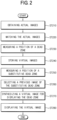
- FIG. 2 is a flow chart illustrating a method of displaying the dead zone of the construction machine using the apparatus in FIG. 1
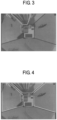
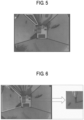
- FIGS. 3 to 8 are images displayed by the method in FIG. 2 .
- the camera unit 110 may obtain the actual images with respect to the omnidirectional views of the cabin in the excavator.
- the camera unit 110 may photograph the views from the cabin to obtain the actual images.
- the actual images may include the front actual images photographed by the front camera 112, the rear actual images photographed by the rear camera 114, the left actual images photographed by the left camera 116, and the right actual images photographed by the right camera 118.
- the image-matching unit 120 may continuously match the actual images.
- the front camera 112 may photograph a zone by a time interval by the rotation of the cabin to obtain two actual images.
- the two actual images may show the same zone.
- the image-matching unit 120 may synthesize the two actual images with each other to from a virtual image.
- the image-matching unit 120 may continuously form the virtual images.
- the virtual images may be transmitted to the controlling unit 160.
- the rotation angle-measuring unit 140 may measure the rotation angle of the boom.
- the measured rotation angle of the boom may be transmitted to the dead zone-detecting unit 150.
- the dead zone-detecting unit 150 may determine whether the dead zone may be generated or not in accordance with the rotation angle of the boom. When the dead zone may be generated, as shown in FIG. 3 , the dead zone-detecting unit 150 may measure a position of the dead zone.
- step ST240 the controlling unit 160 may store a virtual image corresponding to the dead zone among the transmitted virtual images. Because the dead zone may be continuously changed in accordance with the continuous rotation of the boom, the controlling unit 160 may continuously store the virtual images corresponding to the continuously changed dead zones.
- the rotation-detecting unit 130 may detect the rotation of the cabin.
- the detected rotation of the cabin may be transmitted to the controlling unit 160.
- the controlling unit 160 may measure a position of the substitutive dead zone of the boom based on the information with respect to the rotation of the boom.
- step ST260 as shown in FIG. 6 , the controlling unit 160 may select a previous image of the substitutive dead zone corresponding to the present dead zone.
- the previous image may show a man not shown on the present image.
- step ST270 the controlling unit 160 may synthesize the previous image of the substitutive dead zone with the present image of the present dead zone to form a virtual image of the dead zone.
- the present image of the present dead zone may not show the man due to the boom, the previous image of the substitutive dead zone may show the man.
- the virtual image of the dead zone may show the man.
- step ST280 as shown in FIG. 8 , the displaying unit 170 may display transmitted from the controlling unit 160. Because the man may exist in the virtual image displayed on the displaying unit 170, the worker may recognize the main in the dead zone by seeing the virtual image so that the negligent accident may be prevented.
- the actual images photographed by the camera unit may be processed to obtain the virtual image of the dead zone generated by the rotation of the boom.
- a worker in the cabin may accurately acknowledge whether a man or a fixture may exist or not in a region in front of the rotation direction of the boom by seeing the virtual image on the displaying unit. Thus, a negligent accident caused by the rotation of the boom may be prevented.
Landscapes
- Engineering & Computer Science (AREA)
- Structural Engineering (AREA)
- Mining & Mineral Resources (AREA)
- Civil Engineering (AREA)
- General Engineering & Computer Science (AREA)
- Signal Processing (AREA)
- Multimedia (AREA)
- Physics & Mathematics (AREA)
- General Physics & Mathematics (AREA)
- Theoretical Computer Science (AREA)
- Mechanical Engineering (AREA)
- Component Parts Of Construction Machinery (AREA)
- Closed-Circuit Television Systems (AREA)
Claims (4)
- Procédé d'affichage d'une zone morte d'un engin de chantier, le procédé comprenant :a) l'obtention (ST210) d'images réelles par rapport à des vues omnidirectionnelles d'une cabine de l'engin de chantier photographiées par une unité de caméra (110) installée au niveau de la cabine, les images réelles incluant des images réelles avant photographiées par une caméra avant (112), des images réelles arrière photographiées par une caméra arrière (114), des images réelles gauches photographiées par une caméra gauche (116), et des images réelles droites photographiées par une caméra droite (118) ;b) la mise en correspondance en continu (ST220) d'images réelles pour former en continu des images virtuelles par la caméra avant (112) qui photographie une zone à un intervalle de temps par une rotation de la cabine pour obtenir deux images réelles montrant la même zone et la synthèse des deux images réelles l'une avec l'autre pour former une image virtuelle respective ;c) la mesure (ST230) d'un angle de rotation d'un outil de travail rotatif relié à la cabine et le fait de déterminer si une zone morte est générée ou non en fonction de l'angle de rotation de l'outil de travail rotatif et, lorsque la zone morte est générée, la mesure d'une position de la zone morte, la zone morte étant une zone positionnée devant une direction de rotation de l'outil de travail et masquée par celui-ci, et non photographiée par l'unité de caméra ;d) le stockage en continu (ST240) d'images virtuelles correspondant à des zones mortes modifiées en continu en fonction d'une rotation continue de l'outil de travail rotatif ;e) comprenant en outre la détection (ST250) d'une rotation de la cabine et la mesure d'une position actuelle d'une zone morte substitutive actuelle de l'outil de travail rotatif sur la base d'informations relatives à une position actuelle de l'outil de travail rotatif ;f) la sélection d'une image virtuelle parmi les images virtuelles stockées, qui correspond à la zone morte substitutive actuelle à la position actuelle de l'outil de travail rotatif, sur la base des informations ; etg) l'affichage (ST280) de l'image virtuelle sélectionnée sur une unité d'affichage (170) de la cabine.
- Utilisation du procédé selon la revendication 1, dans un engin de chantier qui comprend une excavatrice, et l'outil de travail comprend un outil de travail rotatif de l'excavatrice.
- Appareil permettant d'afficher une zone morte d'un engin de chantier, l'appareil comprenant des moyens pour réaliser les étapes de la revendication 1, les moyens comprenant :a) une unité de caméra (110) configurée pour photographier des images réelles par rapport à des vues omnidirectionnelles d'une cabine dans l'engin de chantier, l'unité de caméra (110) étant installée au niveau de la cabine, les images réelles incluant des images réelles avant photographiées par une caméra avant (112), des images réelles arrière photographiées par une caméra arrière (114), des images réelles gauches photographiées par une caméra gauche (116), et des images réelles droites photographiées par une caméra droite (118), conçue pour réaliser l'étape a) de la revendication 1 ;b) une unité de comparaison d'images (120) configurée pour traiter les images réelles obtenues à partir de l'unité de caméra (110) et effectuer l'étape b) de la revendication 1 ;c) une unité de commande (160) configurée pour obtenir une image virtuelle par rapport à la zone morte générée par un outil de travail rotatif, qui est relié à la cabine, parmi les images réelles traitées par l'unité de comparaison d'images, conçue pour réaliser les étapes d) et f) de la revendication 1 ;d) une unité d'affichage (170) configurée pour afficher l'image virtuelle obtenue par l'unité de commande (160) conçue pour réaliser l'étape g) de la revendication 1 ;e1) une unité de mesure d'angle de rotation (140) configurée pour mesurer un angle de rotation de l'outil de travail rotatif et pour transmettre un signal de l'angle mesuré à l'unité de commande (160), conçue pour effectuer la mesure de l'angle de rotation à l'étape c) de la revendication 1 ;e2) une unité de détection de rotation (130) configurée pour détecter une rotation de la cabine et pour transmettre un signal de la rotation détectée à l'unité de commande (160) et conçue pour effectuer l'étape e) de la revendication 1 ; etf) une unité de détection de zone morte (150) configurée pour détecter une position de la zone morte en fonction d'un angle de rotation de l'outil de travail rotatif conçue pour effectuer la détermination et la mesure de la position à l'étape c).
- Engin de chantier qui comprend une excavatrice et un outil de travail rotatif constitué d'une flèche de l'excavatrice, et l'appareil selon la revendication 3.
Applications Claiming Priority (2)
| Application Number | Priority Date | Filing Date | Title |
|---|---|---|---|
| KR1020150035809A KR102426631B1 (ko) | 2015-03-16 | 2015-03-16 | 건설 기계의 사각 영역 표시 방법 및 이를 수행하기 위한 장치 |
| EP16160253.7A EP3078779A3 (fr) | 2015-03-16 | 2016-03-15 | Procédé d'affichage d'une zone morte d'une machine de construction et appareil permettant de l'exécuter |
Related Parent Applications (2)
| Application Number | Title | Priority Date | Filing Date |
|---|---|---|---|
| EP16160253.7A Division EP3078779A3 (fr) | 2015-03-16 | 2016-03-15 | Procédé d'affichage d'une zone morte d'une machine de construction et appareil permettant de l'exécuter |
| EP16160253.7A Division-Into EP3078779A3 (fr) | 2015-03-16 | 2016-03-15 | Procédé d'affichage d'une zone morte d'une machine de construction et appareil permettant de l'exécuter |
Publications (2)
| Publication Number | Publication Date |
|---|---|
| EP3141663A1 EP3141663A1 (fr) | 2017-03-15 |
| EP3141663B1 true EP3141663B1 (fr) | 2025-06-11 |
Family
ID=56081206
Family Applications (2)
| Application Number | Title | Priority Date | Filing Date |
|---|---|---|---|
| EP16160253.7A Withdrawn EP3078779A3 (fr) | 2015-03-16 | 2016-03-15 | Procédé d'affichage d'une zone morte d'une machine de construction et appareil permettant de l'exécuter |
| EP16194111.7A Active EP3141663B1 (fr) | 2015-03-16 | 2016-03-15 | Procédé d'affichage d'un angle mort d'une machine de construction et appareil permettant de l'exécuter |
Family Applications Before (1)
| Application Number | Title | Priority Date | Filing Date |
|---|---|---|---|
| EP16160253.7A Withdrawn EP3078779A3 (fr) | 2015-03-16 | 2016-03-15 | Procédé d'affichage d'une zone morte d'une machine de construction et appareil permettant de l'exécuter |
Country Status (3)
| Country | Link |
|---|---|
| US (1) | US10060098B2 (fr) |
| EP (2) | EP3078779A3 (fr) |
| KR (1) | KR102426631B1 (fr) |
Families Citing this family (7)
| Publication number | Priority date | Publication date | Assignee | Title |
|---|---|---|---|---|
| WO2016140016A1 (fr) * | 2015-03-03 | 2016-09-09 | 日立建機株式会社 | Dispositif de surveillance des environs d'un véhicule |
| US10011976B1 (en) | 2017-01-03 | 2018-07-03 | Caterpillar Inc. | System and method for work tool recognition |
| WO2021054756A1 (fr) | 2019-09-20 | 2021-03-25 | 주식회사 와이즈오토모티브 | Dispositif de génération d'images frontales pour équipements lourds |
| WO2021054757A1 (fr) * | 2019-09-20 | 2021-03-25 | 주식회사 와이즈오토모티브 | Dispositif de génération d'image avant pour équipement de construction |
| KR20220066673A (ko) | 2020-11-16 | 2022-05-24 | 현대두산인프라코어(주) | 상부체의 회전을 검출하기 위한 굴착기 및 그의 동작 방법 |
| JP7705789B2 (ja) * | 2021-12-01 | 2025-07-10 | 日立建機株式会社 | 作業機械の物体検知システム |
| JP7733563B2 (ja) * | 2021-12-17 | 2025-09-03 | 日立建機株式会社 | ショベル向け周囲監視システム |
Citations (1)
| Publication number | Priority date | Publication date | Assignee | Title |
|---|---|---|---|---|
| EP2631374A1 (fr) * | 2010-10-22 | 2013-08-28 | Hitachi Construction Machinery Co., Ltd. | Dispositif de contrôle périphérique de machine de travail |
Family Cites Families (35)
| Publication number | Priority date | Publication date | Assignee | Title |
|---|---|---|---|---|
| JPH1037252A (ja) * | 1996-07-22 | 1998-02-10 | Shin Caterpillar Mitsubishi Ltd | 車両周辺表示方法およびその装置 |
| JP3351984B2 (ja) * | 1997-04-22 | 2002-12-03 | 国土交通省関東地方整備局長 | 作業用走行車の視界改善装置および方法 |
| JP2002314990A (ja) * | 2001-04-12 | 2002-10-25 | Auto Network Gijutsu Kenkyusho:Kk | 車両周辺視認装置 |
| US7212653B2 (en) * | 2001-12-12 | 2007-05-01 | Kabushikikaisha Equos Research | Image processing system for vehicle |
| US20060034535A1 (en) * | 2004-08-10 | 2006-02-16 | Koch Roger D | Method and apparatus for enhancing visibility to a machine operator |
| JP4321543B2 (ja) * | 2006-04-12 | 2009-08-26 | トヨタ自動車株式会社 | 車両周辺監視装置 |
| JP4847913B2 (ja) * | 2007-03-30 | 2011-12-28 | 日立建機株式会社 | 作業機械周辺監視装置 |
| JP5143481B2 (ja) | 2007-06-28 | 2013-02-13 | 住友建機株式会社 | 建設機械用モニター装置 |
| JP4977667B2 (ja) * | 2008-09-02 | 2012-07-18 | 日立建機株式会社 | 作業機械の視野補助装置 |
| JP5216010B2 (ja) * | 2009-01-20 | 2013-06-19 | 本田技研工業株式会社 | ウインドシールド上の雨滴を同定するための方法及び装置 |
| JP4951639B2 (ja) * | 2009-03-02 | 2012-06-13 | 日立建機株式会社 | 周囲監視装置を備えた作業機械 |
| US9440591B2 (en) * | 2009-05-13 | 2016-09-13 | Deere & Company | Enhanced visibility system |
| JP5108837B2 (ja) * | 2009-07-13 | 2012-12-26 | クラリオン株式会社 | 車両用死角映像表示システムと車両用死角映像表示方法 |
| KR101123738B1 (ko) * | 2009-08-21 | 2012-03-16 | 고려대학교 산학협력단 | 중장비 동작 안전 모니터링 시스템 및 방법 |
| JP5158051B2 (ja) | 2009-09-18 | 2013-03-06 | 三菱自動車工業株式会社 | 運転支援装置 |
| IL201336A (en) * | 2009-10-01 | 2014-03-31 | Rafael Advanced Defense Sys | System and method for assisting navigation of a vehicle in circumstances where there is a possibility of the view being obscured |
| KR101640602B1 (ko) * | 2009-12-15 | 2016-07-18 | 두산인프라코어 주식회사 | 건설기계의 사각지대 표시 장치 및 그 방법 |
| JP5550970B2 (ja) * | 2010-04-12 | 2014-07-16 | 住友重機械工業株式会社 | 画像生成装置及び操作支援システム |
| JP5269026B2 (ja) * | 2010-09-29 | 2013-08-21 | 日立建機株式会社 | 作業機械の周囲監視装置 |
| JP5497617B2 (ja) * | 2010-11-16 | 2014-05-21 | 住友重機械工業株式会社 | 画像生成装置及び操作支援システム |
| KR101735116B1 (ko) * | 2011-01-24 | 2017-05-15 | 두산인프라코어 주식회사 | 건설중장비의 운행정보 기록장치 |
| JP5750344B2 (ja) * | 2011-09-16 | 2015-07-22 | 日立建機株式会社 | 作業機の周囲監視装置 |
| CN103857851B (zh) * | 2011-10-19 | 2016-03-09 | 住友重机械工业株式会社 | 回转作业机械及回转作业机械的控制方法 |
| EP2808455B1 (fr) * | 2012-01-27 | 2018-05-30 | Doosan Infracore Co., Ltd. | Dispositif améliorant la stabilité de fonctionnement d'engins de chantier |
| KR102007535B1 (ko) * | 2012-01-30 | 2019-08-05 | 두산인프라코어 주식회사 | 건설기계의 화면표시장치 |
| JP5781978B2 (ja) * | 2012-05-22 | 2015-09-24 | 株式会社小松製作所 | ダンプトラック |
| JP6003226B2 (ja) * | 2012-05-23 | 2016-10-05 | 株式会社デンソー | 車両周囲画像表示制御装置および車両周囲画像表示制御プログラム |
| JP5814187B2 (ja) * | 2012-06-07 | 2015-11-17 | 日立建機株式会社 | 自走式産業機械の表示装置 |
| DE102013002079A1 (de) * | 2013-02-06 | 2014-08-07 | Volvo Construction Equipment Germany GmbH | Baumaschine |
| KR102123127B1 (ko) * | 2013-12-06 | 2020-06-15 | 두산인프라코어 주식회사 | 화면모드 선택 장치 및 방법 |
| US9460340B2 (en) * | 2014-01-31 | 2016-10-04 | Google Inc. | Self-initiated change of appearance for subjects in video and images |
| US20180120098A1 (en) * | 2015-04-24 | 2018-05-03 | Hitachi, Ltd. | Volume Estimation Apparatus, Working Machine Including the Same, and Volume Estimation System |
| US9871968B2 (en) * | 2015-05-22 | 2018-01-16 | Caterpillar Inc. | Imaging system for generating a surround-view image |
| US9902322B2 (en) * | 2015-10-30 | 2018-02-27 | Bendix Commercial Vehicle Systems Llc | Filling in surround view areas blocked by mirrors or other vehicle parts |
| US20170132476A1 (en) * | 2015-11-08 | 2017-05-11 | Otobrite Electronics Inc. | Vehicle Imaging System |
-
2015
- 2015-03-16 KR KR1020150035809A patent/KR102426631B1/ko active Active
-
2016
- 2016-03-14 US US15/069,288 patent/US10060098B2/en active Active
- 2016-03-15 EP EP16160253.7A patent/EP3078779A3/fr not_active Withdrawn
- 2016-03-15 EP EP16194111.7A patent/EP3141663B1/fr active Active
Patent Citations (1)
| Publication number | Priority date | Publication date | Assignee | Title |
|---|---|---|---|---|
| EP2631374A1 (fr) * | 2010-10-22 | 2013-08-28 | Hitachi Construction Machinery Co., Ltd. | Dispositif de contrôle périphérique de machine de travail |
Also Published As
| Publication number | Publication date |
|---|---|
| US20160273195A1 (en) | 2016-09-22 |
| KR20160111102A (ko) | 2016-09-26 |
| EP3078779A2 (fr) | 2016-10-12 |
| KR102426631B1 (ko) | 2022-07-28 |
| US10060098B2 (en) | 2018-08-28 |
| EP3141663A1 (fr) | 2017-03-15 |
| EP3078779A3 (fr) | 2016-12-28 |
Similar Documents
| Publication | Publication Date | Title |
|---|---|---|
| EP3141663B1 (fr) | Procédé d'affichage d'un angle mort d'une machine de construction et appareil permettant de l'exécuter | |
| KR102509346B1 (ko) | 교정 작업 지원 시스템 | |
| KR101854065B1 (ko) | 작업기의 작동 상태 검출 시스템 및 작업기 | |
| JP5759798B2 (ja) | 建設機械制御システム | |
| US10544567B2 (en) | Method and system for monitoring a rotatable implement of a machine | |
| CN111868335B (zh) | 远程操作系统以及主操作装置 | |
| US9790666B2 (en) | Calibration system, work machine, and calibration method | |
| JP4740890B2 (ja) | 建設機械および建設機械の後進移動ガイダンス方法 | |
| JP6322612B2 (ja) | 施工管理システム及び形状計測方法 | |
| US10527413B2 (en) | Outside recognition device | |
| US20160344931A1 (en) | Imaging system for generating a surround-view image | |
| KR101944816B1 (ko) | 굴삭 작업 검측 자동화 시스템 | |
| JP6585697B2 (ja) | 施工管理システム | |
| CN106460373B (zh) | 评价装置 | |
| JP2016065422A (ja) | 外界認識装置および外界認識装置を用いた掘削機械 | |
| CN111819333A (zh) | 液压挖掘机及系统 | |
| JP6606230B2 (ja) | 形状計測システム | |
| JP7073146B2 (ja) | 建設機械、建設機械の表示装置、及び、建設機械の管理装置 | |
| CN111587448A (zh) | 远端附属设备辨别装置 | |
| JP6659641B2 (ja) | 3次元モデル作成装置 | |
| WO2022234697A1 (fr) | Dispositif de traitement d'image, procédé de traitement d'image et programme | |
| JP2021156000A (ja) | 作業機械 | |
| KR20150105701A (ko) | 건설장비의 후방 인식 시스템 및 방법 |
Legal Events
| Date | Code | Title | Description |
|---|---|---|---|
| PUAI | Public reference made under article 153(3) epc to a published international application that has entered the european phase |
Free format text: ORIGINAL CODE: 0009012 |
|
| STAA | Information on the status of an ep patent application or granted ep patent |
Free format text: STATUS: THE APPLICATION HAS BEEN PUBLISHED |
|
| AC | Divisional application: reference to earlier application |
Ref document number: 3078779 Country of ref document: EP Kind code of ref document: P |
|
| AK | Designated contracting states |
Kind code of ref document: A1 Designated state(s): AL AT BE BG CH CY CZ DE DK EE ES FI FR GB GR HR HU IE IS IT LI LT LU LV MC MK MT NL NO PL PT RO RS SE SI SK SM TR |
|
| AX | Request for extension of the european patent |
Extension state: BA ME |
|
| STAA | Information on the status of an ep patent application or granted ep patent |
Free format text: STATUS: REQUEST FOR EXAMINATION WAS MADE |
|
| 17P | Request for examination filed |
Effective date: 20170915 |
|
| RBV | Designated contracting states (corrected) |
Designated state(s): AL AT BE BG CH CY CZ DE DK EE ES FI FR GB GR HR HU IE IS IT LI LT LU LV MC MK MT NL NO PL PT RO RS SE SI SK SM TR |
|
| STAA | Information on the status of an ep patent application or granted ep patent |
Free format text: STATUS: EXAMINATION IS IN PROGRESS |
|
| 17Q | First examination report despatched |
Effective date: 20210330 |
|
| RAP3 | Party data changed (applicant data changed or rights of an application transferred) |
Owner name: HYUNDAI DOOSAN INFRACORE CO., LTD. |
|
| RAP3 | Party data changed (applicant data changed or rights of an application transferred) |
Owner name: HD HYUNDAI INFRACORE CO., LTD. |
|
| GRAP | Despatch of communication of intention to grant a patent |
Free format text: ORIGINAL CODE: EPIDOSNIGR1 |
|
| STAA | Information on the status of an ep patent application or granted ep patent |
Free format text: STATUS: GRANT OF PATENT IS INTENDED |
|
| INTG | Intention to grant announced |
Effective date: 20250218 |
|
| GRAS | Grant fee paid |
Free format text: ORIGINAL CODE: EPIDOSNIGR3 |
|
| GRAA | (expected) grant |
Free format text: ORIGINAL CODE: 0009210 |
|
| STAA | Information on the status of an ep patent application or granted ep patent |
Free format text: STATUS: THE PATENT HAS BEEN GRANTED |
|
| AC | Divisional application: reference to earlier application |
Ref document number: 3078779 Country of ref document: EP Kind code of ref document: P |
|
| AK | Designated contracting states |
Kind code of ref document: B1 Designated state(s): AL AT BE BG CH CY CZ DE DK EE ES FI FR GB GR HR HU IE IS IT LI LT LU LV MC MK MT NL NO PL PT RO RS SE SI SK SM TR |
|
| REG | Reference to a national code |
Ref country code: GB Ref legal event code: FG4D |
|
| REG | Reference to a national code |
Ref country code: CH Ref legal event code: EP |
|
| REG | Reference to a national code |
Ref country code: DE Ref legal event code: R096 Ref document number: 602016092519 Country of ref document: DE |
|
| REG | Reference to a national code |
Ref country code: IE Ref legal event code: FG4D |
|
| PG25 | Lapsed in a contracting state [announced via postgrant information from national office to epo] |
Ref country code: ES Free format text: LAPSE BECAUSE OF FAILURE TO SUBMIT A TRANSLATION OF THE DESCRIPTION OR TO PAY THE FEE WITHIN THE PRESCRIBED TIME-LIMIT Effective date: 20250611 Ref country code: FI Free format text: LAPSE BECAUSE OF FAILURE TO SUBMIT A TRANSLATION OF THE DESCRIPTION OR TO PAY THE FEE WITHIN THE PRESCRIBED TIME-LIMIT Effective date: 20250611 |
|
| REG | Reference to a national code |
Ref country code: LT Ref legal event code: MG9D |
|
| PG25 | Lapsed in a contracting state [announced via postgrant information from national office to epo] |
Ref country code: GR Free format text: LAPSE BECAUSE OF FAILURE TO SUBMIT A TRANSLATION OF THE DESCRIPTION OR TO PAY THE FEE WITHIN THE PRESCRIBED TIME-LIMIT Effective date: 20250912 Ref country code: NO Free format text: LAPSE BECAUSE OF FAILURE TO SUBMIT A TRANSLATION OF THE DESCRIPTION OR TO PAY THE FEE WITHIN THE PRESCRIBED TIME-LIMIT Effective date: 20250911 |
|
| REG | Reference to a national code |
Ref country code: NL Ref legal event code: MP Effective date: 20250611 |
|
| PG25 | Lapsed in a contracting state [announced via postgrant information from national office to epo] |
Ref country code: BG Free format text: LAPSE BECAUSE OF FAILURE TO SUBMIT A TRANSLATION OF THE DESCRIPTION OR TO PAY THE FEE WITHIN THE PRESCRIBED TIME-LIMIT Effective date: 20250611 |
|
| PG25 | Lapsed in a contracting state [announced via postgrant information from national office to epo] |
Ref country code: HR Free format text: LAPSE BECAUSE OF FAILURE TO SUBMIT A TRANSLATION OF THE DESCRIPTION OR TO PAY THE FEE WITHIN THE PRESCRIBED TIME-LIMIT Effective date: 20250611 |
|
| PG25 | Lapsed in a contracting state [announced via postgrant information from national office to epo] |
Ref country code: RS Free format text: LAPSE BECAUSE OF FAILURE TO SUBMIT A TRANSLATION OF THE DESCRIPTION OR TO PAY THE FEE WITHIN THE PRESCRIBED TIME-LIMIT Effective date: 20250911 |
|
| PG25 | Lapsed in a contracting state [announced via postgrant information from national office to epo] |
Ref country code: LV Free format text: LAPSE BECAUSE OF FAILURE TO SUBMIT A TRANSLATION OF THE DESCRIPTION OR TO PAY THE FEE WITHIN THE PRESCRIBED TIME-LIMIT Effective date: 20250611 |
|
| PG25 | Lapsed in a contracting state [announced via postgrant information from national office to epo] |
Ref country code: NL Free format text: LAPSE BECAUSE OF FAILURE TO SUBMIT A TRANSLATION OF THE DESCRIPTION OR TO PAY THE FEE WITHIN THE PRESCRIBED TIME-LIMIT Effective date: 20250611 |
|
| PG25 | Lapsed in a contracting state [announced via postgrant information from national office to epo] |
Ref country code: PT Free format text: LAPSE BECAUSE OF FAILURE TO SUBMIT A TRANSLATION OF THE DESCRIPTION OR TO PAY THE FEE WITHIN THE PRESCRIBED TIME-LIMIT Effective date: 20251013 |
|
| REG | Reference to a national code |
Ref country code: AT Ref legal event code: MK05 Ref document number: 1802381 Country of ref document: AT Kind code of ref document: T Effective date: 20250611 |
|
| PG25 | Lapsed in a contracting state [announced via postgrant information from national office to epo] |
Ref country code: IS Free format text: LAPSE BECAUSE OF FAILURE TO SUBMIT A TRANSLATION OF THE DESCRIPTION OR TO PAY THE FEE WITHIN THE PRESCRIBED TIME-LIMIT Effective date: 20251011 |
|
| PG25 | Lapsed in a contracting state [announced via postgrant information from national office to epo] |
Ref country code: AT Free format text: LAPSE BECAUSE OF FAILURE TO SUBMIT A TRANSLATION OF THE DESCRIPTION OR TO PAY THE FEE WITHIN THE PRESCRIBED TIME-LIMIT Effective date: 20250611 Ref country code: SM Free format text: LAPSE BECAUSE OF FAILURE TO SUBMIT A TRANSLATION OF THE DESCRIPTION OR TO PAY THE FEE WITHIN THE PRESCRIBED TIME-LIMIT Effective date: 20250611 |
|
| PG25 | Lapsed in a contracting state [announced via postgrant information from national office to epo] |
Ref country code: CZ Free format text: LAPSE BECAUSE OF FAILURE TO SUBMIT A TRANSLATION OF THE DESCRIPTION OR TO PAY THE FEE WITHIN THE PRESCRIBED TIME-LIMIT Effective date: 20250611 |
|
| PG25 | Lapsed in a contracting state [announced via postgrant information from national office to epo] |
Ref country code: PL Free format text: LAPSE BECAUSE OF FAILURE TO SUBMIT A TRANSLATION OF THE DESCRIPTION OR TO PAY THE FEE WITHIN THE PRESCRIBED TIME-LIMIT Effective date: 20250611 |
|
| PG25 | Lapsed in a contracting state [announced via postgrant information from national office to epo] |
Ref country code: EE Free format text: LAPSE BECAUSE OF FAILURE TO SUBMIT A TRANSLATION OF THE DESCRIPTION OR TO PAY THE FEE WITHIN THE PRESCRIBED TIME-LIMIT Effective date: 20250611 |
|
| PG25 | Lapsed in a contracting state [announced via postgrant information from national office to epo] |
Ref country code: SK Free format text: LAPSE BECAUSE OF FAILURE TO SUBMIT A TRANSLATION OF THE DESCRIPTION OR TO PAY THE FEE WITHIN THE PRESCRIBED TIME-LIMIT Effective date: 20250611 Ref country code: RO Free format text: LAPSE BECAUSE OF FAILURE TO SUBMIT A TRANSLATION OF THE DESCRIPTION OR TO PAY THE FEE WITHIN THE PRESCRIBED TIME-LIMIT Effective date: 20250611 |
|
| REG | Reference to a national code |
Ref country code: DE Ref legal event code: R097 Ref document number: 602016092519 Country of ref document: DE |
|
| PGFP | Annual fee paid to national office [announced via postgrant information from national office to epo] |
Ref country code: GB Payment date: 20260313 Year of fee payment: 11 |
|
| PG25 | Lapsed in a contracting state [announced via postgrant information from national office to epo] |
Ref country code: DK Free format text: LAPSE BECAUSE OF FAILURE TO SUBMIT A TRANSLATION OF THE DESCRIPTION OR TO PAY THE FEE WITHIN THE PRESCRIBED TIME-LIMIT Effective date: 20250611 |
|
| PGFP | Annual fee paid to national office [announced via postgrant information from national office to epo] |
Ref country code: DE Payment date: 20260305 Year of fee payment: 11 |
|
| PG25 | Lapsed in a contracting state [announced via postgrant information from national office to epo] |
Ref country code: IT Free format text: LAPSE BECAUSE OF FAILURE TO SUBMIT A TRANSLATION OF THE DESCRIPTION OR TO PAY THE FEE WITHIN THE PRESCRIBED TIME-LIMIT Effective date: 20250611 |
|
| PLBE | No opposition filed within time limit |
Free format text: ORIGINAL CODE: 0009261 |
|
| STAA | Information on the status of an ep patent application or granted ep patent |
Free format text: STATUS: NO OPPOSITION FILED WITHIN TIME LIMIT |
|
| PGFP | Annual fee paid to national office [announced via postgrant information from national office to epo] |
Ref country code: FR Payment date: 20260309 Year of fee payment: 11 |
|
| REG | Reference to a national code |
Ref country code: CH Ref legal event code: L10 Free format text: ST27 STATUS EVENT CODE: U-0-0-L10-L00 (AS PROVIDED BY THE NATIONAL OFFICE) Effective date: 20260423 |