EP3141505B1 - Sheet processing apparatus and corresponding image forming apparatus - Google Patents
Sheet processing apparatus and corresponding image forming apparatus Download PDFInfo
- Publication number
- EP3141505B1 EP3141505B1 EP16187564.6A EP16187564A EP3141505B1 EP 3141505 B1 EP3141505 B1 EP 3141505B1 EP 16187564 A EP16187564 A EP 16187564A EP 3141505 B1 EP3141505 B1 EP 3141505B1
- Authority
- EP
- European Patent Office
- Prior art keywords
- sheet
- sheets
- speed
- thrust
- folding
- Prior art date
- Legal status (The legal status is an assumption and is not a legal conclusion. Google has not performed a legal analysis and makes no representation as to the accuracy of the status listed.)
- Active
Links
Images


Classifications
-
- G—PHYSICS
- G03—PHOTOGRAPHY; CINEMATOGRAPHY; ANALOGOUS TECHNIQUES USING WAVES OTHER THAN OPTICAL WAVES; ELECTROGRAPHY; HOLOGRAPHY
- G03G—ELECTROGRAPHY; ELECTROPHOTOGRAPHY; MAGNETOGRAPHY
- G03G15/00—Apparatus for electrographic processes using a charge pattern
- G03G15/65—Apparatus which relate to the handling of copy material
- G03G15/6538—Devices for collating sheet copy material, e.g. sorters, control, copies in staples form
- G03G15/6541—Binding sets of sheets, e.g. by stapling, glueing
-
- B—PERFORMING OPERATIONS; TRANSPORTING
- B65—CONVEYING; PACKING; STORING; HANDLING THIN OR FILAMENTARY MATERIAL
- B65H—HANDLING THIN OR FILAMENTARY MATERIAL, e.g. SHEETS, WEBS, CABLES
- B65H45/00—Folding thin material
- B65H45/12—Folding articles or webs with application of pressure to define or form crease lines
- B65H45/16—Rotary folders
-
- B—PERFORMING OPERATIONS; TRANSPORTING
- B41—PRINTING; LINING MACHINES; TYPEWRITERS; STAMPS
- B41J—TYPEWRITERS; SELECTIVE PRINTING MECHANISMS, i.e. MECHANISMS PRINTING OTHERWISE THAN FROM A FORME; CORRECTION OF TYPOGRAPHICAL ERRORS
- B41J29/00—Details of, or accessories for, typewriters or selective printing mechanisms not otherwise provided for
- B41J29/38—Drives, motors, controls or automatic cut-off devices for the entire printing mechanism
- B41J29/393—Devices for controlling or analysing the entire machine ; Controlling or analysing mechanical parameters involving printing of test patterns
-
- B—PERFORMING OPERATIONS; TRANSPORTING
- B31—MAKING ARTICLES OF PAPER, CARDBOARD OR MATERIAL WORKED IN A MANNER ANALOGOUS TO PAPER; WORKING PAPER, CARDBOARD OR MATERIAL WORKED IN A MANNER ANALOGOUS TO PAPER
- B31F—MECHANICAL WORKING OR DEFORMATION OF PAPER, CARDBOARD OR MATERIAL WORKED IN A MANNER ANALOGOUS TO PAPER
- B31F1/00—Mechanical deformation without removing material, e.g. in combination with laminating
- B31F1/08—Creasing
-
- B—PERFORMING OPERATIONS; TRANSPORTING
- B41—PRINTING; LINING MACHINES; TYPEWRITERS; STAMPS
- B41F—PRINTING MACHINES OR PRESSES
- B41F13/00—Common details of rotary presses or machines
- B41F13/54—Auxiliary folding, cutting, collecting or depositing of sheets or webs
- B41F13/56—Folding or cutting
-
- B—PERFORMING OPERATIONS; TRANSPORTING
- B65—CONVEYING; PACKING; STORING; HANDLING THIN OR FILAMENTARY MATERIAL
- B65H—HANDLING THIN OR FILAMENTARY MATERIAL, e.g. SHEETS, WEBS, CABLES
- B65H37/00—Article or web delivery apparatus incorporating devices for performing specified auxiliary operations
- B65H37/04—Article or web delivery apparatus incorporating devices for performing specified auxiliary operations for securing together articles or webs, e.g. by adhesive, stitching or stapling
-
- B—PERFORMING OPERATIONS; TRANSPORTING
- B65—CONVEYING; PACKING; STORING; HANDLING THIN OR FILAMENTARY MATERIAL
- B65H—HANDLING THIN OR FILAMENTARY MATERIAL, e.g. SHEETS, WEBS, CABLES
- B65H37/00—Article or web delivery apparatus incorporating devices for performing specified auxiliary operations
- B65H37/06—Article or web delivery apparatus incorporating devices for performing specified auxiliary operations for folding
-
- B—PERFORMING OPERATIONS; TRANSPORTING
- B65—CONVEYING; PACKING; STORING; HANDLING THIN OR FILAMENTARY MATERIAL
- B65H—HANDLING THIN OR FILAMENTARY MATERIAL, e.g. SHEETS, WEBS, CABLES
- B65H45/00—Folding thin material
- B65H45/02—Folding limp material without application of pressure to define or form crease lines
- B65H45/04—Folding sheets
-
- B—PERFORMING OPERATIONS; TRANSPORTING
- B65—CONVEYING; PACKING; STORING; HANDLING THIN OR FILAMENTARY MATERIAL
- B65H—HANDLING THIN OR FILAMENTARY MATERIAL, e.g. SHEETS, WEBS, CABLES
- B65H45/00—Folding thin material
- B65H45/12—Folding articles or webs with application of pressure to define or form crease lines
- B65H45/18—Oscillating or reciprocating blade folders
-
- B—PERFORMING OPERATIONS; TRANSPORTING
- B65—CONVEYING; PACKING; STORING; HANDLING THIN OR FILAMENTARY MATERIAL
- B65H—HANDLING THIN OR FILAMENTARY MATERIAL, e.g. SHEETS, WEBS, CABLES
- B65H45/00—Folding thin material
- B65H45/12—Folding articles or webs with application of pressure to define or form crease lines
- B65H45/30—Folding in combination with creasing, smoothing or application of adhesive
-
- B—PERFORMING OPERATIONS; TRANSPORTING
- B65—CONVEYING; PACKING; STORING; HANDLING THIN OR FILAMENTARY MATERIAL
- B65H—HANDLING THIN OR FILAMENTARY MATERIAL, e.g. SHEETS, WEBS, CABLES
- B65H2301/00—Handling processes for sheets or webs
- B65H2301/40—Type of handling process
- B65H2301/45—Folding, unfolding
- B65H2301/4505—Folding bound sheets, e.g. stapled sheets
-
- B—PERFORMING OPERATIONS; TRANSPORTING
- B65—CONVEYING; PACKING; STORING; HANDLING THIN OR FILAMENTARY MATERIAL
- B65H—HANDLING THIN OR FILAMENTARY MATERIAL, e.g. SHEETS, WEBS, CABLES
- B65H2301/00—Handling processes for sheets or webs
- B65H2301/50—Auxiliary process performed during handling process
- B65H2301/51—Modifying a characteristic of handled material
- B65H2301/516—Securing handled material to another material
-
- B—PERFORMING OPERATIONS; TRANSPORTING
- B65—CONVEYING; PACKING; STORING; HANDLING THIN OR FILAMENTARY MATERIAL
- B65H—HANDLING THIN OR FILAMENTARY MATERIAL, e.g. SHEETS, WEBS, CABLES
- B65H2511/00—Dimensions; Position; Numbers; Identification; Occurrences
- B65H2511/30—Numbers, e.g. of windings or rotations
-
- B—PERFORMING OPERATIONS; TRANSPORTING
- B65—CONVEYING; PACKING; STORING; HANDLING THIN OR FILAMENTARY MATERIAL
- B65H—HANDLING THIN OR FILAMENTARY MATERIAL, e.g. SHEETS, WEBS, CABLES
- B65H2513/00—Dynamic entities; Timing aspects
- B65H2513/10—Speed
-
- B—PERFORMING OPERATIONS; TRANSPORTING
- B65—CONVEYING; PACKING; STORING; HANDLING THIN OR FILAMENTARY MATERIAL
- B65H—HANDLING THIN OR FILAMENTARY MATERIAL, e.g. SHEETS, WEBS, CABLES
- B65H2513/00—Dynamic entities; Timing aspects
- B65H2513/10—Speed
- B65H2513/11—Speed angular
-
- B—PERFORMING OPERATIONS; TRANSPORTING
- B65—CONVEYING; PACKING; STORING; HANDLING THIN OR FILAMENTARY MATERIAL
- B65H—HANDLING THIN OR FILAMENTARY MATERIAL, e.g. SHEETS, WEBS, CABLES
- B65H2801/00—Application field
- B65H2801/03—Image reproduction devices
-
- B—PERFORMING OPERATIONS; TRANSPORTING
- B65—CONVEYING; PACKING; STORING; HANDLING THIN OR FILAMENTARY MATERIAL
- B65H—HANDLING THIN OR FILAMENTARY MATERIAL, e.g. SHEETS, WEBS, CABLES
- B65H2801/00—Application field
- B65H2801/24—Post -processing devices
- B65H2801/27—Devices located downstream of office-type machines
-
- B—PERFORMING OPERATIONS; TRANSPORTING
- B65—CONVEYING; PACKING; STORING; HANDLING THIN OR FILAMENTARY MATERIAL
- B65H—HANDLING THIN OR FILAMENTARY MATERIAL, e.g. SHEETS, WEBS, CABLES
- B65H2801/00—Application field
- B65H2801/24—Post -processing devices
- B65H2801/31—Devices located downstream of industrial printers
Definitions
- the present disclosure relates to a sheet processing apparatus for processing sheets.
- a technique for the pressing of a folding portion of the sheet in a linear manner in advance so as to prevent the problem of the cracking of a back portion on an outer side of a folded sheet (hereinafter, referred to as a back crack), from occurring is also known (Japanese Patent Laid-Open No. 2014-227236 ).
- Fig. 1 is a cross-sectional view schematically illustrating the printer 1000 according to an exemplary embodiment of the present disclosure.
- the printer 1000 includes a printer main body 600 that forms an image on a sheet, and a sheet processing apparatus 200.
- the sheet processing apparatus 200 is configured so as to be detachable from the printer main body 600.
- the sheet processing apparatus 200 is mounted on the printer main body 600, the printer main body 600 capable of being used alone, as an option.
- a detachable sheet processing apparatus 200 description will be given using a detachable sheet processing apparatus 200; however, the sheet processing apparatus 200 and the printer main body 600 may be integral.
- the position where a user faces an operation unit 610 to perform various input/setting operations on the printer 1000 is referred to as a "front side" of the printer 1000, and the rear side of the apparatus is referred to as a "back side”.
- Fig. 1 illustrates a configuration of the printer 1000 viewed from the front side.
- the sheet processing apparatus 200 is connected to a lateral portion of the printer main body 600.
- the printer main body 600 includes a sheet storing unit 602 that stores sheets therein, and a feeding path 603 that conveys a sheet fed from the sheet storing unit 602. Furthermore, the printer main body 600 includes an image forming unit 604 serving as an image forming member that forms an image on a sheet S fed through the feeding path 603. The sheet S on which an image has been formed with the image forming unit 604 is conveyed from the printer main body 600 to the sheet processing apparatus 200 with a discharge roller 607.
- the sheet processing apparatus 200 includes a creasing device 400 and a finisher 100.
- the creasing device 400 includes pairs of conveyance rollers 421, 422, and 423 that convey the sheet sent from the printer main body 600, a detection sensor 424 that detects the sheet, and a creasing unit 410 that performs creasing on the sheet.
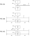
- the creasing unit 410 includes an upper member 412 that is provided with a projection portion and that is capable of moving up and down, and a lower member 411 provided with a recess portion corresponding to the projection portion.
- the upper member 412 receiving a drive from a creasing motor moves up and down.
- the projection portion of the upper member 412 extends in a sheet width direction that is orthogonal to a sheet conveyance direction.
- the recess portion of the lower member 411 extends in the sheet width direction that is orthogonal to the sheet conveyance direction.
- the recess portion of the lower member 411 is disposed so as to be capable of being fitted into the projection portion of the upper member 412.
- the finisher 100 is a device that performs a finishing process on the sheet that has been sent from the creasing device 400.
- the finisher 100 includes a conveyance path 103 that receives and conveys the sheet that has been sent from the creasing device 400.
- the sheet S that has been conveyed to the conveyance path 103 is discharged to an upper stacking tray 136 by a pair of discharge rollers 120.
- a conveyance path 121 branches from the conveyance path 103.
- the conveyance path 121 guides the sheet to a processing unit 138.
- the processing unit 138 performs finishing processes, such as a binding process binding the sheets, on the sheets.
- the sheet that has passed through the processing unit 138 is discharged to a lower stacking tray 137 by a discharge roller 130.
- a conveyance path 133 branches from the conveyance path 121.
- the conveyance path 133 guides the sheet to a saddle stitching processing unit 800.
- the saddle stitching processing unit 800 performs finishing processes, such as a folding process that folds the sheets.
- the saddle stitching processing unit 800 will be described in detail later.
- the sheet that has been folded in the saddle stitching processing unit 800 is discharged on the lower stacking tray 137 by a pair of folded sheet discharge rollers 136.
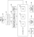
- Fig. 2 is a block diagram of a CPU circuit unit 630 that controls the printer 1000 according to the present exemplary embodiment.
- Fig. 3 is a block diagram of a finisher control unit 636 that is provided in the finisher 100 and that controls the finisher 100.
- Fig. 4 is a block diagram of a creasing device control unit 638 that is provided in the creasing device 400 and that controls the creasing device 400.
- the CPU circuit unit 630 includes a CPU 629, a ROM 631, and a RAM 650. Furthermore, the CPU circuit unit 630 is electrically connected to an image signal control unit 634, a printer control unit 635, and the finisher control unit 636.
- the CPU 629 controls the image signal control unit 634, the printer control unit 635, the finisher control unit 636, the creasing device control unit 638, and the like according to a program stored in the ROM 631 and instruction information input from the operation unit 610.
- the RAM 650 is used as an area for temporarily storing control data and as a work area for calculation associated with the control.
- the printer control unit 635 controls the printer main body 600.
- An external interface 637 is an interface for connecting an external computer 620 and the printer main body 600.
- the external interface 637 develops print data input from the external computer 620 into an image and outputs image data to the image signal control unit 634.
- the image data output to the image signal control unit 634 is output to the printer control unit 635 and is formed into an image in the image forming unit 604.
- the finisher control unit 636 includes a CPU (a microcomputer) 701, a RAM 702, a ROM 703, an input/output unit (I/O) 705, a communication interface 706, and a network interface 704. Furthermore, the finisher control unit 636 includes a conveyance control unit 707 that controls a conveying operation of the sheet, and a process control unit 708 that controls the operation of the processing unit 138. Furthermore, the finisher control unit 636 includes a saddle stitching control unit 711 that controls the saddle stitching processing unit 800.
- the creasing device control unit 638 includes a CPU (a microcomputer) 451, a RAM 453, a ROM 452, and an interface 454 for communicating with the CPU circuit unit 630 of the printer main body 600 and the finisher control unit 636. Furthermore, the creasing device control unit 638 includes a conveyance motor control unit 455 that controls a conveyance drive motor 441 that drives the pairs of conveyance rollers 421, 422, and 423. The creasing device control unit 638 includes a creasing motor control unit 456 that controls a creasing drive motor 442 that generates driving force that moves the upper member 412. A signal from the detection sensor 424 is input to the creasing device control unit 638. Operation of Creasing Device
- the creasing device control unit 638 controls the conveyance drive motor 441 such that the sheet is temporarily stopped at a positon in which the middle of the creasing unit 410 and the middle of the sheet S in the conveyance direction coincide each other.
- the creasing device control unit 638 receives the information on the length of the sheet S in the conveyance direction in advance through communication with the CPU 629.
- the creasing device control unit 638 controls the creasing drive motor 442 so that the upper member 412 is lowered. By lowering the upper member 412, a creasing process is performed on the sheet nipped between the upper member 412 and the lower member 411. The upper member 412 is lifted. As illustrated in Fig. 5C , with the creasing process a groove-shaped crease S-C is formed in the sheet. The creased sheet is conveyed once again and is delivered to the finisher 100. With the above operation, the creasing device 400 is capable of performing a creasing process at the middle of the sheet S in the conveyance direction.
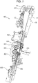
- Fig. 7 is a cross-sectional view of the saddle stitching processing unit 800.
- the saddle stitching processing unit 800 includes a processing tray 15 on which the sheet discharged downwards by the entrance roller 801 is loaded.
- the saddle stitching processing unit 800 further includes a stapler 820 (a binding unit) for binding the stack of sheets, a thrust plate 803 for thrusting the sheet loaded on the processing tray 15, and folding rollers 819 that conveys the sheets that have been thrusted by the thrust plate 803 and that have been folded into two.
- a leading edge stopper 805 that receives a lower end of the sheet is disposed at a lower portion of the processing tray 15.
- a trailing edge pressor 11 is disposed at an upper portion of the processing tray 15.
- a tapping member 12, an intermediate roller 804, and an alignment roller 802 are disposed at positions that oppose the processing tray 15.
- the entrance roller 801 is driven by a saddle entrance conveyance motor 851, the thrust plate 803 by a thrust drive motor 858 (see Fig. 3 ), and the folding rollers 819 by a folding roller drive motor 857.
- the leading edge stopper 805 is driven by a leading edge stopper moving motor 852, and the trailing edge pressor 11 by a holding member moving motor 854.
- the tapping member 12 is driven by a tapping member moving motor 853, the intermediate roller 804 by an intermediate motor moving motor 855, and the alignment roller 802 by an alignment roller moving motor 856.
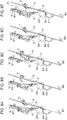
- a sheet S1 conveyed by the entrance roller 801 is conveyed so as to abut against the leading edge stopper 805 serving as a restriction member in the conveyance direction with the intermediate roller 804 and the alignment roller 802.
- the leading edge stopper 805 serving as a restriction member in the conveyance direction with the intermediate roller 804 and the alignment roller 802.
- alignment of the sheet in the conveyance direction is performed.
- alignment in a direction orthogonal to the conveyance direction is performed with an alignment plate 815.
- the trailing edge pressor 11 is opened, and as in Fig. 8C , the tapping member 12 urges the sheet S1 towards the processing tray 15.
- the leading edge stopper 805 serving as a restriction member in the conveyance direction with the intermediate roller 804 and the alignment roller 802.
- the trailing edge pressor 11 is closed and the tapping member 12 is returned to a standby position side. In the above state, the next sheet can be received. Urging the sheet trailing edge of the sheet towards the right side in Fig. 8C with the tapping operation and the pressing operation to avoid collision between the trailing edge of the loaded sheet and the leading edge of the next sheet is referred to as a trailing edge sorting.
- a next sheet S2 is conveyed by the entrance roller 801. Similar to the leading sheet S1, alignment in the conveyance direction and the orthogonal direction is performed. After the trailing edge pressor 11 is opened and the sheet S2 is urged towards the processing tray 15 side with the tapping member 12 the trailing edge pressor 11 is closed. After performing alignment of the sheet, urging of the sheet towards the processing tray 15 side, and the pressing operation on the trailing edge of the sheet to the last sheet Sn, a binding process of the stack of sheets is performed with the stapler 820. Note that the leading edge stopper 805 is at a standby position where the distance from the staple position to the stopper is half the sheet length. The stapler 820 performs a stapling process at the middle of the sheet received by the leading edge stopper 805.
- the stack of sheets S folded by rotating the folding rollers 819 is formed at the same time as the stack of sheets S is guided to the nip of the folding rollers 819 with the thrust plate 803.
- the operation of folding with the folding rollers 819 while thrusting with the thrust plate 803 will be referred to as thrusting and folding.
- the alignment of each sheet, the stapling process on each stack of sheets, and the thrusting and folding operation are repeated to the last stack of sheets.
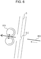
- Fig. 6 is a diagram schematically illustrating a state immediately before thrusting with the thrust plate 803.
- the crease S-C formed on the sheet with the creasing device 400 protrudes on the side opposite the folding rollers 819, that is, on the thrust plate 803 side.
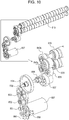
- the folding rollers 819 operate with the folding roller drive motor 857 as the driving source.
- a drive of the folding roller drive motor 857 is transmitted through a folding drive belt 831, a first folding drive gear 832, and a second folding drive gear 833.
- the drive of the folding roller drive motor 857 is transmitted through a third folding drive gear 834, a folding drive transmission shaft 835, and a fourth folding drive gear 836.
- the drive of the folding roller drive motor 857 is transmitted through a fifth folding drive gear 837, sixth folding drive gear 838, and a seventh folding drive gear 839.
- a rotational drive is transmitted from the sixth folding drive gear 838 to a folding roller drive gear 840a that is engaged with the folding roller 819 on the lower side.
- the rotational drive is transmitted from the seventh folding drive gear 839 to a folding roller drive gear 840b that is engaged with the folding roller 819 on the upper side.
- the folding roller drive motor 857 is a DC motor, and the driving speed of the folding roller drive motor 857 can be changed by an electric current input by the finisher control unit 636. Furthermore, the finisher control unit 636 monitors the actual rotation speed with an encoder 841 mounted in the folding roller drive motor 857 and a folding speed detection sensor 859. Then, by having the finisher control unit 636 perform a control of feeding back, from the monitoring result, the speed fluctuation into a current value in real time, it will be possible to perform accurate control towards the targeted speed.
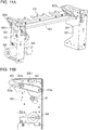
- FIG. 11A is a perspective view of the thrust unit
- Fig. 11B is a side view.
- the thrust plate 803 operates (reciprocates) with the thrust drive motor 858 as the driving source.
- the drive of the thrust drive motor 858 is transmitted to a first thrust drive gear 821 and a second thrust drive gear 822 through a gear and a belt (not shown).
- the second thrust drive gear 822 interlocks with the thrust link cam 824 through a drive shaft 823 and is rotated.
- the second thrust drive gear 822 is engaged with a thrust link plate 825-1 on the front side
- the thrust link cam 824 is engaged with a thrust link plate 825-2 on the back side.
- the thrust link plates 825 include link engagement portions 825a that engage with the second thrust drive gear 822 and the thrust link cam 824, and thrust plate engagement portions 825b that engage with the thrust plate 803.
- the thrust plate engagement portions 825b are guided by a guide portion 826a of a front side thrust frame 826 and a guide portion 827a of a rear side thrust frame 827.
- the drive of the thrust drive motor 858 is transmitted into the rotations of the first thrust drive gear 821, the second thrust drive gear 822, and the thrust link cam 824.
- the thrust plate engagement portions 825b operate in a direction (a direction of the arrow in Fig. 11B ) that is parallel to the guide portions 826a and 827a of the thrust frames 826 and 827, and the thrust plate 803 operates in the same direction.
- the thrust drive motor 858 is, similar to the folding roller drive motor 857, a DC motor.
- the driving speed of the thrust drive motor 858 can be changed with the electric current input by the finisher control unit 636.
- the folding roller drive motor 857 also includes an encoder (not shown) and a thrust speed detection sensor 860, and similar to the folding roller drive motor 857, performs a control such that the speed becomes uniform by feeding back the speed fluctuation into a current value.
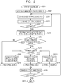
- Fig. 12 Details of the operation of the folding process will be described with reference to a flowchart in Fig. 12 , and Fig. 13 .
- the operation pertaining to Fig. 12 is performed with the finisher control unit 636 controlling the motors through a program stored in the ROM 703 and through the RAM 702 as a work area.
- the components such as the alignment plate 815 and the leading edge stopper 805, move to the standby positions that receive the sheet (S201 and 202 in Fig. 12 ).
- the alignment plate 815 stands by at a position that is slightly wider than the sheet width and, as described above, the leading edge stopper 805 stands by at a position that is down by half the sheet length from the stapling position.
- the sheet that has been delivered by the finisher is conveyed to the processing tray 15 of the saddle stitching processing unit 800 through each conveyance rollers (S203) and the alignment in the sheet conveyance direction, the alignment in the width direction, and the trailing edge sorting operation are performed (S204). The above operation is performed to the last sheet of each stack (S205).
- the stapling process is executed by the stapler 820. Note that in a case in which the number of sheets is one, the stapling process is not performed. Furthermore, when no stapling process is set, the stapling process is not performed. Subsequently, the stack of sheets is moved to a position where the middle of the stack of sheets coincides with a nip center of the folding rollers 819 (S206).
- a moving velocity (hereinafter, referred to as a thrust speed) when the thrust plate 803 thrusts the sheet is changed.
- the finisher control unit 636 checks whether the sheet that is to be the cover sheet among the stack of sheets is a sheet S on which the crease S-C has been formed as illustrated in Fig. 6 (S207).
- the sheet that is to be the cover sheet is a sheet that covers the other sheets when folded, and is the sheet that is in contact with the folding rollers 819.
- the finisher control unit 636 determines whether the sheet is a sheet S on which crease S-C has been formed on the basis of a signal that is transmitted from the printer main body 600. Note that whether to perform a creasing process S-C is input by the user operating the operation unit 610.
- the finisher control unit 636 checks the number of sheets in the stack of sheets (S208). When the creasing process has been performed on the sheet and the number of sheets is three or more (S209), the finisher control unit 636 controls the thrust drive motor 858 so that the thrust speed is 100% (S210).
- the thrust speed of 100% is the maximum speed in which the thrust plate 803 moves (370 mm/s in the present exemplary embodiment). Since a conveyance speed (a folding speed) of the folding rollers 819 is 175 mm/s, the thrust speed is a speed that exceeds twice the speed of the folding rollers 819. Note that the conveyance speed of the folding rollers 819 is a circumferential speed of the folding rollers 819.
- the finisher control unit 636 controls the thrust drive motor 858 so that the thrust speed is 70% (S211 and S212).
- the finisher control unit 636 controls the thrust drive motor 858 so that the thrust speed is 50% (S213 and S214).
- the thrust speed of 50% is 185 mm/s in the present exemplary embodiment.
- the thrust speed of 50% is a speed set slightly higher than the conveyance speed (175 mm/s) of the folding rollers 819. If, supposedly, the thrust speed is lower than the conveyance speed of the folding rollers 819, the folding rollers 819 idle on the sheet that is to be the cover sheet. Then, a problem may disadvantageously occur in which the sheet that is to be the cover sheet becomes damaged. Accordingly, in the present exemplary embodiment, the thrust speed is set higher than the conveyance speed of the folding rollers 819 so as to prevent the above problem from occurring.
- the difference between the conveyance speed of the folding rollers 819 and the thrust speed of the thrust plate 803 is set smaller compared with when the number of sheets is equivalent or more than the predetermined number of sheets (two).
- the finisher control unit 636 determines that no creasing process has been performed on the sheet that is to be the cover sheet (NO in S207), regardless of the number of sheets, the finisher control unit 636 controls the thrust drive motor 858 so that the thrust plate 803 uniformly moves at the thrust speed of 100%.
- the booklet that has been formed by performing thrusting and folding in the above manner is conveyed with the folding rollers 819 and the pair of folded sheet discharge rollers 136, and is discharged on the lower stacking tray 137 (S215).
- the above operation is continued to the last stack and the job is ended (S215 and S216).
- the finisher control unit 636 sets the thrust speed of the thrust plate 803 by referring to a table that has been stored in advance and that is associated with the number of sheets folded and with whether a crease has been formed.
- the thrust plate mark is a mark that is created when the thrust plate 803 pushes the sheets into the folding rollers 819.
- the crease S-C in the sheet which has been formed by the creasing device 400 by thrusting of the thrust plate 803, may disadvantageously return to a flat state. If the crease S-C of the sheet returns to a flat state, back crack may be created disadvantageously after the sheets are folded.
- the thrust speed is low; accordingly, the crease S-C of the sheet formed by the creasing device 400 rarely returns to a flat state due to being thrust by the thrust plate. Accordingly, back cracks can be prevented. Meanwhile, although the thrust speed is low, since the number of sheets is small, tear of the cover sheet does not occur.
- the thrust speed is low when the number of sheets is large, a tear of the cover sheet may disadvantageously occur.
- the thrust speed is high when the number of sheets is large; accordingly, the tear of the cover sheet rarely occurs.
- the crease S-C of the sheet that is to be the cover sheet does not return to a flat state by being thrusted, back crack can be prevented from being created.
- a mark S-T is referred to as a thrust plate mark. Since the sheet is nipped by the thrust plate 803 and the folding rollers 819, the thrust plate mark occurs on a surface of the sheet that is in contact with the thrust plate 803 and the surface of the sheet that is in contact with the folding rollers 819.
- the thrust speed is at high speed when the number of sheets is large, and it has been revealed through an experiment that when the number of sheets in the stack of sheets is large, no thrust plate mark occurs.
- the following is thought to be the reason for no thrust plate mark occurring even with a high thrust speed when the number of sheets in the stack of sheets is large. It is thought that when the number of sheets in the stack of sheets is large, the impact to the sheets when the sheets are nipped with the thrust plate 803 and the folding rollers 819 is relieved by air layers between the sheets.
- the thrust speed is set to a high speed regardless of the number of sheets.
- a thrust plate mark, a tear of the cover sheet, and a back crack of the cover sheet can all be prevented.
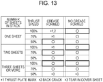
- FIG. 13 A result of an experiment conducted while changing the number of sheets and the thrust speed is illustrated in Fig. 13 .
- Fig. 13 portions surrounded by a thick line is the control employed in the present exemplary embodiment.
- ⁇ indicates that the thrust plate mark, the tear of the cover sheet, and the back crack of the cover sheet have not occurred.
- the number of sheets was one, and the thrust speed was at 100%, a thrust plate mark and a back crack occurred.
- the number of sheets was one, and the thrust speed was at 70%, a thrust plate mark occurred.
- the number of sheets was three or more and the thrust speed was at 50%, a tear of the cover sheet occurred. Note that the creasing process is for preventing a back crack from occurring.
- the user selects whether there is to be a creasing process by whether the type of paper is one in which a back crack occurs, for example. Accordingly, in "NO CREASING FORMED" in Fig. 13 , the experiment result of whether there was a back crack is omitted.
- the speed difference between the conveyance speed of the folding rollers 819 and the thrust speed may be changed according to the number of sheets in the stack of sheets by, for example, as illustrated in a modification below, not changing the thrust speed but by changing the conveyance speed of the folding rollers 819.
- the thrust speed of the thrust plate 803 is set to 370 mm/s. Furthermore, when folding the sheets on which a crease has been formed, the speed of the folding rollers 819 is changed according to the number of sheets in the stack of sheets such that the speed difference with the thrust speed in a case in which the number of sheets is large is larger than the speed difference with the thrust speed in a case in which the number of sheets is small.
- the speed of the folding rollers 819 is set to 175 mm/s.
- the speed of the folding rollers 819 is set to 286 mm/s.
- the conveyance speed of the folding rollers 819 is set to 360 mm/s.
- both of the speed of the folding rollers 819 and the thrust speed may be changed according to the number of sheets in the stack of sheets.
- an exemplification of a mode in which information of whether a creasing process has been performed on the sheet is transmitted by the creasing device 400 to the finisher 100 through the CPU 629 to switch the control in the finisher 100.
- the configuration may be as below. That is, the creasing unit 410 is provided inside the finisher 100.
- the control unit inside the finisher 100 may control the operation of the creasing unit 410 and control the speed of the folding rollers 819.
- the CPU circuit unit 630 of the printer main body 600 may directly control the saddle stitching processing unit 800.
- the protrusion of the crease S-C formed by the creasing device 400 is oriented towards the inner side when the sheets are folded.
- the protrusion of the crease S-C formed by the creasing unit may be oriented towards the outer side when the sheets are folded. In other words, even when the protrusion of the crease S-C formed by the creasing device 400 is oriented towards the outer side when the sheets are folded, it is effective in preventing a back crack of the cover sheet from occurring.
Landscapes
- Engineering & Computer Science (AREA)
- Textile Engineering (AREA)
- Mechanical Engineering (AREA)
- Physics & Mathematics (AREA)
- General Physics & Mathematics (AREA)
- Folding Of Thin Sheet-Like Materials, Special Discharging Devices, And Others (AREA)
Applications Claiming Priority (1)
| Application Number | Priority Date | Filing Date | Title |
|---|---|---|---|
| JP2015181160A JP6604789B2 (ja) | 2015-09-14 | 2015-09-14 | シート処理装置及び画像形成装置 |
Publications (2)
| Publication Number | Publication Date |
|---|---|
| EP3141505A1 EP3141505A1 (en) | 2017-03-15 |
| EP3141505B1 true EP3141505B1 (en) | 2018-07-04 |
Family
ID=56883694
Family Applications (1)
| Application Number | Title | Priority Date | Filing Date |
|---|---|---|---|
| EP16187564.6A Active EP3141505B1 (en) | 2015-09-14 | 2016-09-07 | Sheet processing apparatus and corresponding image forming apparatus |
Country Status (7)
| Country | Link |
|---|---|
| US (1) | US10054892B2 (enExample) |
| EP (1) | EP3141505B1 (enExample) |
| JP (1) | JP6604789B2 (enExample) |
| KR (1) | KR101974699B1 (enExample) |
| CN (1) | CN106516855B (enExample) |
| PH (1) | PH12016000314A1 (enExample) |
| SG (1) | SG10201607297PA (enExample) |
Families Citing this family (3)
| Publication number | Priority date | Publication date | Assignee | Title |
|---|---|---|---|---|
| US11203506B2 (en) * | 2019-12-26 | 2021-12-21 | Canon Finetech Nisca Inc. | Sheet processing apparatus and image forming system |
| JP7815780B2 (ja) * | 2022-01-18 | 2026-02-18 | 京セラドキュメントソリューションズ株式会社 | シート折り装置およびそれを備えたシート後処理装置 |
| US12180023B2 (en) * | 2022-08-18 | 2024-12-31 | Ncr Corporation | Corrugating rollers apparatus and method for a media storage bin in a self-service terminal |
Family Cites Families (29)
| Publication number | Priority date | Publication date | Assignee | Title |
|---|---|---|---|---|
| DE69608227T2 (de) * | 1995-12-28 | 2001-01-04 | Canon Aptex K.K., Mitsukaido | Apparat zum Falzen von Blättern |
| JP2001002317A (ja) * | 1999-06-21 | 2001-01-09 | Ricoh Elemex Corp | 画像形成装置の記録紙後処理装置 |
| JP2002308521A (ja) | 2001-04-12 | 2002-10-23 | Konica Corp | 後処理装置及び画像形成装置 |
| JP2003054832A (ja) | 2001-08-21 | 2003-02-26 | Konica Corp | 用紙後処理方法、用紙後処理装置及び画像形成装置 |
| JP3990240B2 (ja) | 2002-09-04 | 2007-10-10 | 株式会社リコー | 用紙処理装置および画像形成システム |
| JP4143445B2 (ja) | 2003-03-07 | 2008-09-03 | キヤノンファインテック株式会社 | シート処理装置及びこれを備えた画像形成装置 |
| US7470227B2 (en) | 2004-08-24 | 2008-12-30 | Ricoh Company, Ltd. | Paper folding apparatus and image forming apparatus using the same |
| JP2007076832A (ja) * | 2005-09-14 | 2007-03-29 | Canon Finetech Inc | シート処理装置及びこれを備えた画像形成装置 |
| JP4227640B2 (ja) * | 2005-11-11 | 2009-02-18 | キヤノン株式会社 | シート処理装置、これを備えた画像形成装置 |
| US7699300B2 (en) | 2007-02-01 | 2010-04-20 | Toshiba Tec Kabushiki Kaisha | Sheet post-processing apparatus |
| US7740238B2 (en) * | 2007-03-02 | 2010-06-22 | Toshiba Tec Kabushiki Kaisha | Sheet processing apparatus |
| US7891647B2 (en) * | 2007-04-20 | 2011-02-22 | Canon Kabushiki Kaisha | Sheet processing apparatus and image forming system |
| US7770876B2 (en) * | 2007-08-28 | 2010-08-10 | Kabushiki Kaisha Toshiba | Creasing device, post-processing apparatus equipped therewith, creasing method, image forming apparatus and crease-added printing method |
| CN101314445B (zh) | 2008-06-18 | 2011-02-02 | 株式会社东芝 | 纸张后处理装置、图像形成装置及纸张后处理方法 |
| JP5328374B2 (ja) * | 2009-01-06 | 2013-10-30 | キヤノン株式会社 | シート処理装置 |
| JP2011093708A (ja) * | 2009-09-30 | 2011-05-12 | Ricoh Co Ltd | 画像形成装置 |
| JP5158065B2 (ja) * | 2009-12-18 | 2013-03-06 | コニカミノルタビジネステクノロジーズ株式会社 | 後処理装置 |
| JP5595116B2 (ja) | 2010-05-17 | 2014-09-24 | キヤノン株式会社 | シート処理装置及び画像形成装置 |
| JP5569246B2 (ja) | 2010-08-17 | 2014-08-13 | 株式会社リコー | 用紙折り装置、用紙処理装置及び画像形成装置 |
| JP5664094B2 (ja) | 2010-10-01 | 2015-02-04 | 株式会社リコー | 用紙処理装置及び画像形成システム |
| JP5605149B2 (ja) * | 2010-10-12 | 2014-10-15 | 株式会社リコー | 筋付け装置及び画像形成システム |
| JP5675308B2 (ja) | 2010-12-07 | 2015-02-25 | キヤノン株式会社 | シート処理装置 |
| JP2012126472A (ja) * | 2010-12-13 | 2012-07-05 | Ricoh Co Ltd | 筋付け装置及び画像形成システム |
| JP5488559B2 (ja) | 2011-10-06 | 2014-05-14 | コニカミノルタ株式会社 | シート後処理装置およびシート折り方法 |
| JP5867183B2 (ja) * | 2012-03-08 | 2016-02-24 | コニカミノルタ株式会社 | 用紙処理装置、これを有する画像形成システム及び用紙折り方法 |
| JP5870986B2 (ja) | 2013-01-18 | 2016-03-01 | 株式会社リコー | シート処理装置及び画像形成システム |
| JP2014227236A (ja) | 2013-05-20 | 2014-12-08 | キヤノン株式会社 | シート処理装置及び画像形成装置 |
| KR20150001324A (ko) * | 2013-06-27 | 2015-01-06 | 삼성전자주식회사 | 인쇄매체 후처리 유닛 및 이를 갖춘 화상형성장치 |
| US9823611B2 (en) * | 2015-04-23 | 2017-11-21 | Canon Finetech Nisca Inc. | Sheet processing device and image forming device provided with the same |
-
2015
- 2015-09-14 JP JP2015181160A patent/JP6604789B2/ja active Active
-
2016
- 2016-09-01 SG SG10201607297PA patent/SG10201607297PA/en unknown
- 2016-09-07 EP EP16187564.6A patent/EP3141505B1/en active Active
- 2016-09-09 US US15/261,060 patent/US10054892B2/en active Active
- 2016-09-09 PH PH12016000314A patent/PH12016000314A1/en unknown
- 2016-09-13 KR KR1020160117947A patent/KR101974699B1/ko active Active
- 2016-09-14 CN CN201610825321.4A patent/CN106516855B/zh active Active
Non-Patent Citations (1)
| Title |
|---|
| None * |
Also Published As
| Publication number | Publication date |
|---|---|
| JP6604789B2 (ja) | 2019-11-13 |
| JP2017057031A (ja) | 2017-03-23 |
| KR20170032199A (ko) | 2017-03-22 |
| KR101974699B1 (ko) | 2019-05-02 |
| CN106516855B (zh) | 2019-09-03 |
| EP3141505A1 (en) | 2017-03-15 |
| US20170075284A1 (en) | 2017-03-16 |
| SG10201607297PA (en) | 2017-04-27 |
| CN106516855A (zh) | 2017-03-22 |
| US10054892B2 (en) | 2018-08-21 |
| PH12016000314A1 (en) | 2018-05-28 |
Similar Documents
| Publication | Publication Date | Title |
|---|---|---|
| JP4922896B2 (ja) | 用紙後処理装置 | |
| JP4829857B2 (ja) | 用紙後処理装置および用紙後処理装置のブレード制御方法 | |
| US10926970B2 (en) | Post-processing apparatus, image forming apparatus incorporating the same, and image forming system incorporating the same | |
| CN114194914B (zh) | 片材折叠装置和具有该片材折叠装置的片材后处理装置 | |
| JP2013018572A (ja) | 冊子搬送装置、画像形成システム及び冊子搬送方法 | |
| US8794615B2 (en) | Sheet post-processing apparatus that performs post-processing on sheet bundle, method of controlling the same, and storage medium | |
| EP3141505B1 (en) | Sheet processing apparatus and corresponding image forming apparatus | |
| JP5671960B2 (ja) | 用紙処理装置及び画像形成システム | |
| EP1772284B1 (en) | Signature spine flattening device, post treatment apparatus and image forming apparatus | |
| JP5994243B2 (ja) | 用紙処理装置 | |
| JP4946478B2 (ja) | 用紙後処理装置 | |
| US10518998B2 (en) | Sheet processing apparatus | |
| JP4846623B2 (ja) | スキュー補正装置、穿孔装置及び画像形成システム | |
| US20170066620A1 (en) | Image forming system capable of coping with shifted saddle-stitching or center-folding position | |
| JP4496841B2 (ja) | 用紙後処理装置 | |
| JP2013147323A (ja) | 用紙処理装置及び画像形成システム | |
| US20250002287A1 (en) | Sheet post-processing apparatus and image forming system including the apparatus | |
| US20240253938A1 (en) | Sheet post-processing apparatus and image forming system including the apparatus | |
| JP2007098875A (ja) | 折り部平坦化装置 | |
| JP5494376B2 (ja) | シート処理システム、画像形成システム及び小口断裁位置決定方法 | |
| JP4701151B2 (ja) | 用紙折り装置、及び画像形成装置 | |
| JP2013230897A (ja) | 用紙処理装置及び画像形成システム | |
| JP2005314093A (ja) | 用紙コンパイル装置 | |
| JP2012006761A (ja) | シート折り装置、シート処理装置、画像形成装置、及びシート折り方法 | |
| JP2013234018A (ja) | 用紙処理装置及び画像形成システム |
Legal Events
| Date | Code | Title | Description |
|---|---|---|---|
| PUAI | Public reference made under article 153(3) epc to a published international application that has entered the european phase |
Free format text: ORIGINAL CODE: 0009012 |
|
| STAA | Information on the status of an ep patent application or granted ep patent |
Free format text: STATUS: THE APPLICATION HAS BEEN PUBLISHED |
|
| AK | Designated contracting states |
Kind code of ref document: A1 Designated state(s): AL AT BE BG CH CY CZ DE DK EE ES FI FR GB GR HR HU IE IS IT LI LT LU LV MC MK MT NL NO PL PT RO RS SE SI SK SM TR |
|
| AX | Request for extension of the european patent |
Extension state: BA ME |
|
| STAA | Information on the status of an ep patent application or granted ep patent |
Free format text: STATUS: REQUEST FOR EXAMINATION WAS MADE |
|
| 17P | Request for examination filed |
Effective date: 20170915 |
|
| RBV | Designated contracting states (corrected) |
Designated state(s): AL AT BE BG CH CY CZ DE DK EE ES FI FR GB GR HR HU IE IS IT LI LT LU LV MC MK MT NL NO PL PT RO RS SE SI SK SM TR |
|
| GRAP | Despatch of communication of intention to grant a patent |
Free format text: ORIGINAL CODE: EPIDOSNIGR1 |
|
| STAA | Information on the status of an ep patent application or granted ep patent |
Free format text: STATUS: GRANT OF PATENT IS INTENDED |
|
| INTG | Intention to grant announced |
Effective date: 20180212 |
|
| GRAS | Grant fee paid |
Free format text: ORIGINAL CODE: EPIDOSNIGR3 |
|
| GRAA | (expected) grant |
Free format text: ORIGINAL CODE: 0009210 |
|
| STAA | Information on the status of an ep patent application or granted ep patent |
Free format text: STATUS: THE PATENT HAS BEEN GRANTED |
|
| AK | Designated contracting states |
Kind code of ref document: B1 Designated state(s): AL AT BE BG CH CY CZ DE DK EE ES FI FR GB GR HR HU IE IS IT LI LT LU LV MC MK MT NL NO PL PT RO RS SE SI SK SM TR |
|
| REG | Reference to a national code |
Ref country code: GB Ref legal event code: FG4D |
|
| REG | Reference to a national code |
Ref country code: CH Ref legal event code: EP |
|
| REG | Reference to a national code |
Ref country code: AT Ref legal event code: REF Ref document number: 1014270 Country of ref document: AT Kind code of ref document: T Effective date: 20180715 |
|
| REG | Reference to a national code |
Ref country code: IE Ref legal event code: FG4D |
|
| REG | Reference to a national code |
Ref country code: DE Ref legal event code: R096 Ref document number: 602016003955 Country of ref document: DE |
|
| REG | Reference to a national code |
Ref country code: NL Ref legal event code: MP Effective date: 20180704 |
|
| REG | Reference to a national code |
Ref country code: LT Ref legal event code: MG4D |
|
| REG | Reference to a national code |
Ref country code: AT Ref legal event code: MK05 Ref document number: 1014270 Country of ref document: AT Kind code of ref document: T Effective date: 20180704 |
|
| PG25 | Lapsed in a contracting state [announced via postgrant information from national office to epo] |
Ref country code: NL Free format text: LAPSE BECAUSE OF FAILURE TO SUBMIT A TRANSLATION OF THE DESCRIPTION OR TO PAY THE FEE WITHIN THE PRESCRIBED TIME-LIMIT Effective date: 20180704 |
|
| PG25 | Lapsed in a contracting state [announced via postgrant information from national office to epo] |
Ref country code: AT Free format text: LAPSE BECAUSE OF FAILURE TO SUBMIT A TRANSLATION OF THE DESCRIPTION OR TO PAY THE FEE WITHIN THE PRESCRIBED TIME-LIMIT Effective date: 20180704 Ref country code: SE Free format text: LAPSE BECAUSE OF FAILURE TO SUBMIT A TRANSLATION OF THE DESCRIPTION OR TO PAY THE FEE WITHIN THE PRESCRIBED TIME-LIMIT Effective date: 20180704 Ref country code: BG Free format text: LAPSE BECAUSE OF FAILURE TO SUBMIT A TRANSLATION OF THE DESCRIPTION OR TO PAY THE FEE WITHIN THE PRESCRIBED TIME-LIMIT Effective date: 20181004 Ref country code: IS Free format text: LAPSE BECAUSE OF FAILURE TO SUBMIT A TRANSLATION OF THE DESCRIPTION OR TO PAY THE FEE WITHIN THE PRESCRIBED TIME-LIMIT Effective date: 20181104 Ref country code: PL Free format text: LAPSE BECAUSE OF FAILURE TO SUBMIT A TRANSLATION OF THE DESCRIPTION OR TO PAY THE FEE WITHIN THE PRESCRIBED TIME-LIMIT Effective date: 20180704 Ref country code: GR Free format text: LAPSE BECAUSE OF FAILURE TO SUBMIT A TRANSLATION OF THE DESCRIPTION OR TO PAY THE FEE WITHIN THE PRESCRIBED TIME-LIMIT Effective date: 20181005 Ref country code: RS Free format text: LAPSE BECAUSE OF FAILURE TO SUBMIT A TRANSLATION OF THE DESCRIPTION OR TO PAY THE FEE WITHIN THE PRESCRIBED TIME-LIMIT Effective date: 20180704 Ref country code: LT Free format text: LAPSE BECAUSE OF FAILURE TO SUBMIT A TRANSLATION OF THE DESCRIPTION OR TO PAY THE FEE WITHIN THE PRESCRIBED TIME-LIMIT Effective date: 20180704 Ref country code: NO Free format text: LAPSE BECAUSE OF FAILURE TO SUBMIT A TRANSLATION OF THE DESCRIPTION OR TO PAY THE FEE WITHIN THE PRESCRIBED TIME-LIMIT Effective date: 20181004 Ref country code: CZ Free format text: LAPSE BECAUSE OF FAILURE TO SUBMIT A TRANSLATION OF THE DESCRIPTION OR TO PAY THE FEE WITHIN THE PRESCRIBED TIME-LIMIT Effective date: 20180704 Ref country code: FI Free format text: LAPSE BECAUSE OF FAILURE TO SUBMIT A TRANSLATION OF THE DESCRIPTION OR TO PAY THE FEE WITHIN THE PRESCRIBED TIME-LIMIT Effective date: 20180704 |
|
| PG25 | Lapsed in a contracting state [announced via postgrant information from national office to epo] |
Ref country code: HR Free format text: LAPSE BECAUSE OF FAILURE TO SUBMIT A TRANSLATION OF THE DESCRIPTION OR TO PAY THE FEE WITHIN THE PRESCRIBED TIME-LIMIT Effective date: 20180704 Ref country code: LV Free format text: LAPSE BECAUSE OF FAILURE TO SUBMIT A TRANSLATION OF THE DESCRIPTION OR TO PAY THE FEE WITHIN THE PRESCRIBED TIME-LIMIT Effective date: 20180704 Ref country code: AL Free format text: LAPSE BECAUSE OF FAILURE TO SUBMIT A TRANSLATION OF THE DESCRIPTION OR TO PAY THE FEE WITHIN THE PRESCRIBED TIME-LIMIT Effective date: 20180704 Ref country code: ES Free format text: LAPSE BECAUSE OF FAILURE TO SUBMIT A TRANSLATION OF THE DESCRIPTION OR TO PAY THE FEE WITHIN THE PRESCRIBED TIME-LIMIT Effective date: 20180704 |
|
| REG | Reference to a national code |
Ref country code: DE Ref legal event code: R097 Ref document number: 602016003955 Country of ref document: DE |
|
| PG25 | Lapsed in a contracting state [announced via postgrant information from national office to epo] |
Ref country code: RO Free format text: LAPSE BECAUSE OF FAILURE TO SUBMIT A TRANSLATION OF THE DESCRIPTION OR TO PAY THE FEE WITHIN THE PRESCRIBED TIME-LIMIT Effective date: 20180704 Ref country code: IT Free format text: LAPSE BECAUSE OF FAILURE TO SUBMIT A TRANSLATION OF THE DESCRIPTION OR TO PAY THE FEE WITHIN THE PRESCRIBED TIME-LIMIT Effective date: 20180704 Ref country code: MC Free format text: LAPSE BECAUSE OF FAILURE TO SUBMIT A TRANSLATION OF THE DESCRIPTION OR TO PAY THE FEE WITHIN THE PRESCRIBED TIME-LIMIT Effective date: 20180704 Ref country code: EE Free format text: LAPSE BECAUSE OF FAILURE TO SUBMIT A TRANSLATION OF THE DESCRIPTION OR TO PAY THE FEE WITHIN THE PRESCRIBED TIME-LIMIT Effective date: 20180704 |
|
| PLBE | No opposition filed within time limit |
Free format text: ORIGINAL CODE: 0009261 |
|
| STAA | Information on the status of an ep patent application or granted ep patent |
Free format text: STATUS: NO OPPOSITION FILED WITHIN TIME LIMIT |
|
| PG25 | Lapsed in a contracting state [announced via postgrant information from national office to epo] |
Ref country code: SM Free format text: LAPSE BECAUSE OF FAILURE TO SUBMIT A TRANSLATION OF THE DESCRIPTION OR TO PAY THE FEE WITHIN THE PRESCRIBED TIME-LIMIT Effective date: 20180704 Ref country code: DK Free format text: LAPSE BECAUSE OF FAILURE TO SUBMIT A TRANSLATION OF THE DESCRIPTION OR TO PAY THE FEE WITHIN THE PRESCRIBED TIME-LIMIT Effective date: 20180704 Ref country code: SK Free format text: LAPSE BECAUSE OF FAILURE TO SUBMIT A TRANSLATION OF THE DESCRIPTION OR TO PAY THE FEE WITHIN THE PRESCRIBED TIME-LIMIT Effective date: 20180704 |
|
| 26N | No opposition filed |
Effective date: 20190405 |
|
| REG | Reference to a national code |
Ref country code: BE Ref legal event code: MM Effective date: 20180930 |
|
| REG | Reference to a national code |
Ref country code: IE Ref legal event code: MM4A |
|
| PG25 | Lapsed in a contracting state [announced via postgrant information from national office to epo] |
Ref country code: LU Free format text: LAPSE BECAUSE OF NON-PAYMENT OF DUE FEES Effective date: 20180907 |
|
| PG25 | Lapsed in a contracting state [announced via postgrant information from national office to epo] |
Ref country code: IE Free format text: LAPSE BECAUSE OF NON-PAYMENT OF DUE FEES Effective date: 20180907 |
|
| PG25 | Lapsed in a contracting state [announced via postgrant information from national office to epo] |
Ref country code: FR Free format text: LAPSE BECAUSE OF NON-PAYMENT OF DUE FEES Effective date: 20180930 Ref country code: BE Free format text: LAPSE BECAUSE OF NON-PAYMENT OF DUE FEES Effective date: 20180930 Ref country code: SI Free format text: LAPSE BECAUSE OF FAILURE TO SUBMIT A TRANSLATION OF THE DESCRIPTION OR TO PAY THE FEE WITHIN THE PRESCRIBED TIME-LIMIT Effective date: 20180704 |
|
| PG25 | Lapsed in a contracting state [announced via postgrant information from national office to epo] |
Ref country code: MT Free format text: LAPSE BECAUSE OF NON-PAYMENT OF DUE FEES Effective date: 20180907 |
|
| PG25 | Lapsed in a contracting state [announced via postgrant information from national office to epo] |
Ref country code: TR Free format text: LAPSE BECAUSE OF FAILURE TO SUBMIT A TRANSLATION OF THE DESCRIPTION OR TO PAY THE FEE WITHIN THE PRESCRIBED TIME-LIMIT Effective date: 20180704 |
|
| PG25 | Lapsed in a contracting state [announced via postgrant information from national office to epo] |
Ref country code: PT Free format text: LAPSE BECAUSE OF FAILURE TO SUBMIT A TRANSLATION OF THE DESCRIPTION OR TO PAY THE FEE WITHIN THE PRESCRIBED TIME-LIMIT Effective date: 20180704 |
|
| REG | Reference to a national code |
Ref country code: CH Ref legal event code: PL |
|
| PG25 | Lapsed in a contracting state [announced via postgrant information from national office to epo] |
Ref country code: HU Free format text: LAPSE BECAUSE OF FAILURE TO SUBMIT A TRANSLATION OF THE DESCRIPTION OR TO PAY THE FEE WITHIN THE PRESCRIBED TIME-LIMIT; INVALID AB INITIO Effective date: 20160907 Ref country code: CY Free format text: LAPSE BECAUSE OF FAILURE TO SUBMIT A TRANSLATION OF THE DESCRIPTION OR TO PAY THE FEE WITHIN THE PRESCRIBED TIME-LIMIT Effective date: 20180704 Ref country code: MK Free format text: LAPSE BECAUSE OF NON-PAYMENT OF DUE FEES Effective date: 20180704 |
|
| PG25 | Lapsed in a contracting state [announced via postgrant information from national office to epo] |
Ref country code: CH Free format text: LAPSE BECAUSE OF NON-PAYMENT OF DUE FEES Effective date: 20190930 Ref country code: LI Free format text: LAPSE BECAUSE OF NON-PAYMENT OF DUE FEES Effective date: 20190930 |
|
| PGFP | Annual fee paid to national office [announced via postgrant information from national office to epo] |
Ref country code: DE Payment date: 20250820 Year of fee payment: 10 |
|
| PGFP | Annual fee paid to national office [announced via postgrant information from national office to epo] |
Ref country code: GB Payment date: 20250820 Year of fee payment: 10 |