EP3141436A1 - Vehicule comprenant au moins une place debout pour un conducteur debout et/ou un passager debout - Google Patents
Vehicule comprenant au moins une place debout pour un conducteur debout et/ou un passager debout Download PDFInfo
- Publication number
- EP3141436A1 EP3141436A1 EP16188034.9A EP16188034A EP3141436A1 EP 3141436 A1 EP3141436 A1 EP 3141436A1 EP 16188034 A EP16188034 A EP 16188034A EP 3141436 A1 EP3141436 A1 EP 3141436A1
- Authority
- EP
- European Patent Office
- Prior art keywords
- vehicle
- standing
- driver
- collecting
- passenger
- Prior art date
- Legal status (The legal status is an assumption and is not a legal conclusion. Google has not performed a legal analysis and makes no representation as to the accuracy of the status listed.)
- Granted
Links
- 230000005484 gravity Effects 0.000 claims description 7
- 239000000463 material Substances 0.000 claims description 4
- 210000000323 shoulder joint Anatomy 0.000 claims description 3
- 210000001562 sternum Anatomy 0.000 claims description 2
- 230000000452 restraining effect Effects 0.000 abstract description 3
- 230000035939 shock Effects 0.000 abstract description 2
- 230000000694 effects Effects 0.000 description 6
- 230000001133 acceleration Effects 0.000 description 5
- 230000002829 reductive effect Effects 0.000 description 5
- 238000000034 method Methods 0.000 description 4
- 238000010521 absorption reaction Methods 0.000 description 3
- 230000003111 delayed effect Effects 0.000 description 3
- NJPPVKZQTLUDBO-UHFFFAOYSA-N novaluron Chemical compound C1=C(Cl)C(OC(F)(F)C(OC(F)(F)F)F)=CC=C1NC(=O)NC(=O)C1=C(F)C=CC=C1F NJPPVKZQTLUDBO-UHFFFAOYSA-N 0.000 description 3
- 230000008569 process Effects 0.000 description 3
- 208000027418 Wounds and injury Diseases 0.000 description 2
- 210000001015 abdomen Anatomy 0.000 description 2
- 230000003750 conditioning effect Effects 0.000 description 2
- 238000010276 construction Methods 0.000 description 2
- 230000006378 damage Effects 0.000 description 2
- 230000007423 decrease Effects 0.000 description 2
- 230000001934 delay Effects 0.000 description 2
- 238000010586 diagram Methods 0.000 description 2
- 239000006260 foam Substances 0.000 description 2
- 208000014674 injury Diseases 0.000 description 2
- 210000002414 leg Anatomy 0.000 description 2
- 230000033001 locomotion Effects 0.000 description 2
- 210000003141 lower extremity Anatomy 0.000 description 2
- 230000000717 retained effect Effects 0.000 description 2
- 230000007704 transition Effects 0.000 description 2
- 206010039203 Road traffic accident Diseases 0.000 description 1
- 230000008901 benefit Effects 0.000 description 1
- 210000000746 body region Anatomy 0.000 description 1
- 210000000481 breast Anatomy 0.000 description 1
- 210000001217 buttock Anatomy 0.000 description 1
- 150000001875 compounds Chemical class 0.000 description 1
- 230000006835 compression Effects 0.000 description 1
- 238000007906 compression Methods 0.000 description 1
- 230000008030 elimination Effects 0.000 description 1
- 238000003379 elimination reaction Methods 0.000 description 1
- 230000010006 flight Effects 0.000 description 1
- 238000007654 immersion Methods 0.000 description 1
- 230000003116 impacting effect Effects 0.000 description 1
- 238000009434 installation Methods 0.000 description 1
- 238000012423 maintenance Methods 0.000 description 1
- 230000014759 maintenance of location Effects 0.000 description 1
- 238000000465 moulding Methods 0.000 description 1
- 210000000056 organ Anatomy 0.000 description 1
- 230000036961 partial effect Effects 0.000 description 1
- 230000001681 protective effect Effects 0.000 description 1
- 230000009467 reduction Effects 0.000 description 1
- 239000012858 resilient material Substances 0.000 description 1
- 230000000276 sedentary effect Effects 0.000 description 1
- 238000004904 shortening Methods 0.000 description 1
- 239000007787 solid Substances 0.000 description 1
- 230000004083 survival effect Effects 0.000 description 1
- 230000001960 triggered effect Effects 0.000 description 1
Images


Classifications
-
- B—PERFORMING OPERATIONS; TRANSPORTING
- B60—VEHICLES IN GENERAL
- B60R—VEHICLES, VEHICLE FITTINGS, OR VEHICLE PARTS, NOT OTHERWISE PROVIDED FOR
- B60R21/00—Arrangements or fittings on vehicles for protecting or preventing injuries to occupants or pedestrians in case of accidents or other traffic risks
- B60R21/02—Occupant safety arrangements or fittings, e.g. crash pads
-
- B—PERFORMING OPERATIONS; TRANSPORTING
- B60—VEHICLES IN GENERAL
- B60N—SEATS SPECIALLY ADAPTED FOR VEHICLES; VEHICLE PASSENGER ACCOMMODATION NOT OTHERWISE PROVIDED FOR
- B60N2/00—Seats specially adapted for vehicles; Arrangement or mounting of seats in vehicles
- B60N2/24—Seats specially adapted for vehicles; Arrangement or mounting of seats in vehicles for particular purposes or particular vehicles
- B60N2/42—Seats specially adapted for vehicles; Arrangement or mounting of seats in vehicles for particular purposes or particular vehicles the seat constructed to protect the occupant from the effect of abnormal g-forces, e.g. crash or safety seats
- B60N2/4207—Seats specially adapted for vehicles; Arrangement or mounting of seats in vehicles for particular purposes or particular vehicles the seat constructed to protect the occupant from the effect of abnormal g-forces, e.g. crash or safety seats characterised by the direction of the g-forces
- B60N2/4214—Seats specially adapted for vehicles; Arrangement or mounting of seats in vehicles for particular purposes or particular vehicles the seat constructed to protect the occupant from the effect of abnormal g-forces, e.g. crash or safety seats characterised by the direction of the g-forces longitudinal
- B60N2/4221—Seats specially adapted for vehicles; Arrangement or mounting of seats in vehicles for particular purposes or particular vehicles the seat constructed to protect the occupant from the effect of abnormal g-forces, e.g. crash or safety seats characterised by the direction of the g-forces longitudinal due to impact coming from the front
-
- B—PERFORMING OPERATIONS; TRANSPORTING
- B60—VEHICLES IN GENERAL
- B60N—SEATS SPECIALLY ADAPTED FOR VEHICLES; VEHICLE PASSENGER ACCOMMODATION NOT OTHERWISE PROVIDED FOR
- B60N2/00—Seats specially adapted for vehicles; Arrangement or mounting of seats in vehicles
- B60N2/24—Seats specially adapted for vehicles; Arrangement or mounting of seats in vehicles for particular purposes or particular vehicles
- B60N2/42—Seats specially adapted for vehicles; Arrangement or mounting of seats in vehicles for particular purposes or particular vehicles the seat constructed to protect the occupant from the effect of abnormal g-forces, e.g. crash or safety seats
- B60N2/4249—Seats specially adapted for vehicles; Arrangement or mounting of seats in vehicles for particular purposes or particular vehicles the seat constructed to protect the occupant from the effect of abnormal g-forces, e.g. crash or safety seats fixed structures, i.e. where neither the seat nor a part thereof are displaced during a crash
-
- B—PERFORMING OPERATIONS; TRANSPORTING
- B60—VEHICLES IN GENERAL
- B60N—SEATS SPECIALLY ADAPTED FOR VEHICLES; VEHICLE PASSENGER ACCOMMODATION NOT OTHERWISE PROVIDED FOR
- B60N2/00—Seats specially adapted for vehicles; Arrangement or mounting of seats in vehicles
- B60N2/24—Seats specially adapted for vehicles; Arrangement or mounting of seats in vehicles for particular purposes or particular vehicles
- B60N2/42—Seats specially adapted for vehicles; Arrangement or mounting of seats in vehicles for particular purposes or particular vehicles the seat constructed to protect the occupant from the effect of abnormal g-forces, e.g. crash or safety seats
- B60N2/427—Seats or parts thereof displaced during a crash
- B60N2/42709—Seats or parts thereof displaced during a crash involving residual deformation or fracture of the structure
-
- B—PERFORMING OPERATIONS; TRANSPORTING
- B60—VEHICLES IN GENERAL
- B60R—VEHICLES, VEHICLE FITTINGS, OR VEHICLE PARTS, NOT OTHERWISE PROVIDED FOR
- B60R21/00—Arrangements or fittings on vehicles for protecting or preventing injuries to occupants or pedestrians in case of accidents or other traffic risks
- B60R21/02—Occupant safety arrangements or fittings, e.g. crash pads
- B60R21/04—Padded linings for the vehicle interior ; Energy absorbing structures associated with padded or non-padded linings
-
- B—PERFORMING OPERATIONS; TRANSPORTING
- B60—VEHICLES IN GENERAL
- B60R—VEHICLES, VEHICLE FITTINGS, OR VEHICLE PARTS, NOT OTHERWISE PROVIDED FOR
- B60R21/00—Arrangements or fittings on vehicles for protecting or preventing injuries to occupants or pedestrians in case of accidents or other traffic risks
- B60R21/02—Occupant safety arrangements or fittings, e.g. crash pads
- B60R21/16—Inflatable occupant restraints or confinements designed to inflate upon impact or impending impact, e.g. air bags
-
- B—PERFORMING OPERATIONS; TRANSPORTING
- B60—VEHICLES IN GENERAL
- B60N—SEATS SPECIALLY ADAPTED FOR VEHICLES; VEHICLE PASSENGER ACCOMMODATION NOT OTHERWISE PROVIDED FOR
- B60N2/00—Seats specially adapted for vehicles; Arrangement or mounting of seats in vehicles
- B60N2/24—Seats specially adapted for vehicles; Arrangement or mounting of seats in vehicles for particular purposes or particular vehicles
- B60N2002/247—Seats specially adapted for vehicles; Arrangement or mounting of seats in vehicles for particular purposes or particular vehicles to support passengers in a half-standing position
-
- B—PERFORMING OPERATIONS; TRANSPORTING
- B60—VEHICLES IN GENERAL
- B60R—VEHICLES, VEHICLE FITTINGS, OR VEHICLE PARTS, NOT OTHERWISE PROVIDED FOR
- B60R21/00—Arrangements or fittings on vehicles for protecting or preventing injuries to occupants or pedestrians in case of accidents or other traffic risks
- B60R2021/003—Arrangements or fittings on vehicles for protecting or preventing injuries to occupants or pedestrians in case of accidents or other traffic risks characterised by occupant or pedestian
- B60R2021/0032—Position of passenger
- B60R2021/0037—Position of passenger standing
-
- B—PERFORMING OPERATIONS; TRANSPORTING
- B60—VEHICLES IN GENERAL
- B60R—VEHICLES, VEHICLE FITTINGS, OR VEHICLE PARTS, NOT OTHERWISE PROVIDED FOR
- B60R21/00—Arrangements or fittings on vehicles for protecting or preventing injuries to occupants or pedestrians in case of accidents or other traffic risks
- B60R21/02—Occupant safety arrangements or fittings, e.g. crash pads
- B60R21/04—Padded linings for the vehicle interior ; Energy absorbing structures associated with padded or non-padded linings
- B60R2021/0407—Padded linings for the vehicle interior ; Energy absorbing structures associated with padded or non-padded linings using gas or liquid as energy absorbing means
-
- B—PERFORMING OPERATIONS; TRANSPORTING
- B60—VEHICLES IN GENERAL
- B60R—VEHICLES, VEHICLE FITTINGS, OR VEHICLE PARTS, NOT OTHERWISE PROVIDED FOR
- B60R21/00—Arrangements or fittings on vehicles for protecting or preventing injuries to occupants or pedestrians in case of accidents or other traffic risks
- B60R21/02—Occupant safety arrangements or fittings, e.g. crash pads
- B60R21/04—Padded linings for the vehicle interior ; Energy absorbing structures associated with padded or non-padded linings
- B60R2021/0442—Padded linings for the vehicle interior ; Energy absorbing structures associated with padded or non-padded linings associated with the roof panel
-
- B—PERFORMING OPERATIONS; TRANSPORTING
- B60—VEHICLES IN GENERAL
- B60R—VEHICLES, VEHICLE FITTINGS, OR VEHICLE PARTS, NOT OTHERWISE PROVIDED FOR
- B60R21/00—Arrangements or fittings on vehicles for protecting or preventing injuries to occupants or pedestrians in case of accidents or other traffic risks
- B60R21/02—Occupant safety arrangements or fittings, e.g. crash pads
- B60R21/16—Inflatable occupant restraints or confinements designed to inflate upon impact or impending impact, e.g. air bags
- B60R21/23—Inflatable members
- B60R21/231—Inflatable members characterised by their shape, construction or spatial configuration
- B60R2021/23169—Inflatable members characterised by their shape, construction or spatial configuration specially adapted for knee protection
-
- B—PERFORMING OPERATIONS; TRANSPORTING
- B60—VEHICLES IN GENERAL
- B60R—VEHICLES, VEHICLE FITTINGS, OR VEHICLE PARTS, NOT OTHERWISE PROVIDED FOR
- B60R21/00—Arrangements or fittings on vehicles for protecting or preventing injuries to occupants or pedestrians in case of accidents or other traffic risks
- B60R21/02—Occupant safety arrangements or fittings, e.g. crash pads
- B60R21/16—Inflatable occupant restraints or confinements designed to inflate upon impact or impending impact, e.g. air bags
- B60R21/23—Inflatable members
- B60R21/231—Inflatable members characterised by their shape, construction or spatial configuration
- B60R2021/23176—Inflatable members characterised by their shape, construction or spatial configuration specially adapted for foot protection
-
- B—PERFORMING OPERATIONS; TRANSPORTING
- B60—VEHICLES IN GENERAL
- B60R—VEHICLES, VEHICLE FITTINGS, OR VEHICLE PARTS, NOT OTHERWISE PROVIDED FOR
- B60R21/00—Arrangements or fittings on vehicles for protecting or preventing injuries to occupants or pedestrians in case of accidents or other traffic risks
- B60R21/02—Occupant safety arrangements or fittings, e.g. crash pads
- B60R21/16—Inflatable occupant restraints or confinements designed to inflate upon impact or impending impact, e.g. air bags
- B60R21/23—Inflatable members
- B60R21/231—Inflatable members characterised by their shape, construction or spatial configuration
- B60R2021/23192—Roof bags, i.e. protecting the occupant in a roll-over situation
-
- B—PERFORMING OPERATIONS; TRANSPORTING
- B60—VEHICLES IN GENERAL
- B60R—VEHICLES, VEHICLE FITTINGS, OR VEHICLE PARTS, NOT OTHERWISE PROVIDED FOR
- B60R21/00—Arrangements or fittings on vehicles for protecting or preventing injuries to occupants or pedestrians in case of accidents or other traffic risks
- B60R21/02—Occupant safety arrangements or fittings, e.g. crash pads
- B60R21/04—Padded linings for the vehicle interior ; Energy absorbing structures associated with padded or non-padded linings
- B60R21/0428—Padded linings for the vehicle interior ; Energy absorbing structures associated with padded or non-padded linings associated with the side doors or panels, e.g. displaced towards the occupants in case of a side collision
-
- B—PERFORMING OPERATIONS; TRANSPORTING
- B60—VEHICLES IN GENERAL
- B60R—VEHICLES, VEHICLE FITTINGS, OR VEHICLE PARTS, NOT OTHERWISE PROVIDED FOR
- B60R21/00—Arrangements or fittings on vehicles for protecting or preventing injuries to occupants or pedestrians in case of accidents or other traffic risks
- B60R21/02—Occupant safety arrangements or fittings, e.g. crash pads
- B60R21/04—Padded linings for the vehicle interior ; Energy absorbing structures associated with padded or non-padded linings
- B60R21/045—Padded linings for the vehicle interior ; Energy absorbing structures associated with padded or non-padded linings associated with the instrument panel or dashboard
-
- B—PERFORMING OPERATIONS; TRANSPORTING
- B60—VEHICLES IN GENERAL
- B60R—VEHICLES, VEHICLE FITTINGS, OR VEHICLE PARTS, NOT OTHERWISE PROVIDED FOR
- B60R21/00—Arrangements or fittings on vehicles for protecting or preventing injuries to occupants or pedestrians in case of accidents or other traffic risks
- B60R21/02—Occupant safety arrangements or fittings, e.g. crash pads
- B60R21/16—Inflatable occupant restraints or confinements designed to inflate upon impact or impending impact, e.g. air bags
- B60R21/23—Inflatable members
- B60R21/231—Inflatable members characterised by their shape, construction or spatial configuration
- B60R21/23138—Inflatable members characterised by their shape, construction or spatial configuration specially adapted for side protection
Definitions
- the invention relates to a vehicle with at least one standing space for a stationary driver and / or a standing passenger, with a front area having at least one impact energy absorbing crumple zone.
- the safety systems commonly used today in road vehicles, in particular seat belts and airbags, are effective only in connection with a seated position of the persons in order to form a coordinated safety system with a deformation area at the front of the vehicle and possibly another deformation area at the rear of the vehicle, the so-called crumple zone.
- a common deceleration of the driver thus secured or of the passengers thus secured takes place together with the vehicle compartment.
- the crumple zones serve to reduce the deceleration forces acting on the occupants. In this way, in modern vehicles, a survival of the vehicle occupants in an impact on an obstacle with a relative speed of about 50 km / h is likely to be assumed.
- the CA 2696407 A1 shows a commercial vehicle in which the driver's seat can be used with raised seat in a normal, sitting position, but the seat can also be folded down so that the driver can control the vehicle in a standing position in a standing position.
- a standing seat for standing passengers carried on public transport is from the DE 198 14 548 C1 known. Again, a little projecting seat allows a standing ajar posture. Transparent blinds in front of and behind the passenger form a restraint system. In the case of heavy braking, the passenger is thrown against the transparent, soft restraint system without seriously injuring himself.
- this system designed for buses is not transferable to other vehicles, in particular it is not suitable for driver's seats, since the driver must have an unobstructed view and unobstructed access to the steering wheel and other controls. It should also be borne in mind that, when in doubt, buses are more likely to be the major accident participant due to their mass and, in any case, are subject to significantly less delays in the event of a collision with a passenger car.
- Stand-operated other vehicles are therefore less used on public roads, but are used in particular for carriage outside are used on public courses on golf courses and are for example in the WO 2006/032275 A2 or JP 62101586 A shown.
- the object of the present invention is thus to allow in a vehicle of the type mentioned a vehicle guidance by a stationary driver and / or a transport of passengers standing or a standing position leaning while at the same time a backup of the driver and / or passengers in the event of an accident.
- This vehicle is based in the basic construction on existing vehicle cells, which have in front of and / or behind the solid parts of the drive train a deformable zone, the so-called crumple zone, which usually also in the event of a rear impact in the rear of the vehicle further deformation range is provided.
- the vehicle according to the invention thus uses the already achieved in the prior art reduction of the forces acting on the human body deceleration forces by structural measures.
- Drivers and passengers are in the vehicle according to the invention, regardless of whether they are freestanding, leaning against a standing seat or driving with an additional foldable seat in half-sitting position, always between a front and a rear catch element, which is resilient and thus not only one fulfilled mechanical restraint function, but in particular shock-absorbing, so energy-consuming.
- the shock absorption or impact absorption goes beyond pure upholstery to reduce the severest injuries at the speeds prevailing in inner city traffic.
- the trapping elements are free of internal, hard stiffening elements to the unobstructed immersion of the body in the collecting elements to the maximum allow elastic compression or maximum soft plastic deformation of the layer (s) in the collecting elements.
- the invention aims to initiate the deceleration of the body largely simultaneously with the passenger compartment, but to decouple it as far as possible from the passenger compartment.
- the body can be braked according to the invention of the other vehicle compartment and the chassis partially independently alone within the resilient collecting elements by its kinetic energy is absorbed by elastic and / or plastic deformation.
- the only connection of the body to the passenger compartment is indirect, since the collecting elements on which it bounces are connected as such to the passenger compartment. The connection is of course only in the areas that do not represent the impact side.
- the deceleration path and hence the deceleration time can be extended. Accordingly, the acceleration acting on the body decreases.
- the body can still move within the resilient foam layers or other layers which form the catching elements when the passenger compartment has already come to a standstill.
- the collecting elements form a very wide collecting surface, which is preferably even wider than the impact surface of the body of the driver or passenger, so that in the event of an impact, the body of the occupant is hurled over the entire surface against the collecting surface and then in the course of the accident against the back catch area is thrown back.
- a point overloading of individual body regions is avoided by the large-area distribution.
- the collecting surfaces extend upwards beyond the center of gravity of the body and preferably end below the shoulder joints so far that at least the driver and possibly also the occupants can place the arms comfortably on the upper side of the collecting elements or on other suitable supporting surfaces.
- the body center of gravity is assumed to be at the level of the upper abdomen, so that the collecting elements should extend at least up to the level of the breast.
- the steering wheel or a bow-shaped handlebar as is common in two-wheelers and quads, is freely accessible according to the invention with the other necessary controls from above the front collecting element. A contact of the driver's upper body with the steering wheel and other controls in an accident is thus avoided even when the driver is thrown to the front collecting surface and there is a strong deformation of the local collecting element.
- the restraint device is designed so that it encloses the upper body of the occupant not only in projected area forward and backward to the direction of travel, but in full.
- the front and the rear collecting element as provided according to the invention minimum equipment are supplemented to a arranged in the middle of the vehicle middle part and expanded to a horseshoe-shaped structure seen from above. The remaining lateral gap in this ring is used for easy entry and exit from the vehicle side.
- a very secure vehicle which also allows fast entry and exit of all occupants and is thus particularly suitable for delivery services, postal delivery and military deployment scenarios, ie for those applications in which a frequent, fast boarding and leaving possible should be.
- the remaining on the entry side opening is preferably closed by an additional catch element which is fixed to the inside of a vehicle door.
- an additional catch element which is fixed to the inside of a vehicle door.
- the vehicle according to the invention since the cost of installation and maintenance and subsequent disposal of sophisticated security systems including sensors and pyrotechnics can be omitted.
- the safety belt itself can be omitted as well as the associated additional systems such as belt tensioners and belt force limiters.
- Even the frontally arranged airbags including the associated sensors are no longer needed at least outside the driver's seat.
- the elimination of the airbags also reduces the risk for accident workers, which can be significantly injured by delayed triggered airbags.
- a load uniformly distributed over the body surface is achieved. Peak loads during the accident are reduced, so that the maximum permissible biomechanical load values are undercut in a normalized, related to the inner city traffic accidents.
- An additional retaining element may be provided to additionally protect the occupants in the event of a vehicle rollover by being held in the all-round secure standing even against vertically acting forces. This can be effected by a simple lap belt system, or in particular by a non-linear vertical extension of the catch elements, so that the person is also retained in the vertical direction.
- a preferred embodiment provides a short, slightly protruding standing seat, which is located in front of the rear collecting surface and is arranged vertically adjustable.
- a height adjustable floor pedestal is preferably provided.
- the arm height of the driver is constant, so that it can easily reach and operate the located above the front collecting element steering and controls regardless of his own height.
- the height of the front collecting element is preferably matched to a so-called standard man with an average height of 1.75 m.
- Much larger riders of 1.90m or more can lower the standing seat to lower their own shoulder height in a slightly propped, slanting downhill posture.
- small persons with a height of about 1.60 m can be brought into an elevated position by adjusting the floor pedestal and the standing seat so that the shoulder height is raised.
- a further preferred embodiment provides to make the collecting elements so adjustable that the distance to the body of the driver with respect to the Vehicle longitudinal axis, possibly also in relation to the vehicle transverse axis, can be easily varied.
- the distance is preferably chosen so that it is only slightly larger than the so-called belt slack in conventional vehicles, so as the way that is covered in the event of an accident without retention effect of the seat belt until it rests taut on the body of the occupant and holds it back.
- the collecting elements are subdivided in zones and the zones are formed of materials of different yielding properties.
- the layers closer to the person should be softer than those behind them.
- the impacting body is thus initially collected soft and it is achieved due to the flexibility of the outer layer, a good pressure distribution, so that a full-surface load on the entire body surface is done and not only a punctual support to individual, exposed surface areas.
- a gradation of the hardness of the collecting elements can also be carried out in height, since due to the lower mass of the lower body of the momentum during impact there is less strong. This also makes it possible to perform the lower portion of a collecting element rebounding by a lower deformation path is provided by a greater hardness of the material and the saved deformation is used to increase the footwell and thus for the convenience of the stationary driver or passenger.
- tactile or pedal elements may be arranged to set the vehicle in motion and to brake.
- the gradation of the material hardness in the vehicle longitudinal direction is harmonized with the course of the crumple zones, so that the loads occurring in the course of the accident are made uniform in the form of delays of varying degrees and peak values of the load are reduced to an extent tolerable for the human body.
- the flexibility of the collecting elements is designed so that first a full-surface conditioning of the body is achieved and then in the expected accident events the delay path beyond the allowed by the respective crumple deformation zone.
- the delay time ie the time interval between accident entry and standstill of the body of the vehicle occupant relative to the ground is extended. Accordingly, the sinks Acceleration as a derivative of speed over time and, consequently, the associated restraining forces acting on the body.
- a vehicle 100 is shown in a plan view, which is a four-wheeled passenger car for four people.
- a rear region 13 of the vehicle 100 is located on the right-hand edge of the image.
- a motor 10 is arranged which is largely undeformable.
- the area between the engine 10 and the vehicle front 11 is formed as a crumple zone 12 so as to be continuously deformed upon collision with another vehicle or obstacle, thereby reducing the deceleration acting on the occupants.
- Another crumple zone 14 is located in the rear region 13.
- the standing room 21 is intended for the driver and the standing room 22 for the passenger. In the rear, two more standing room 23, 24 are provided for other passengers.
- a front catch element 33 In front of the standing room 21, 22 is a front catch element 33. On top of a handlebar or a steering wheel 17 is arranged. Behind the front standing places 21, 22 is a collecting element 33, which serves as a rear catch element for the people on the front standing places 21, 22 and at the same time forms a front catch element for the passengers on the rear standing places 23, 24. Behind the second row, a rear catch element 35 is arranged.
- For lateral support serve dividing elements 37, 39, which are each arranged between the passengers standing in a row next to each other.
- On the insides of all four vehicle doors 15 also additional catch elements 32 are arranged so that with closed vehicle doors 15 on each of the standing room 21, ..., 24 a complete ring of collecting elements 31 ... 37 to the driver and passengers ,
- each standing room 21, ..., 24 is also provided in each case a headrest 36 which projects beyond the other collecting elements 31, 32, 33, 35, 37, 39 away upwards.
- a small standing seat 34 at each standing place 21, 22, 23, 24 allows the persons to take a comfortable, ajar posture.
- a vehicle 100 ' is shown in plan, which is a four-wheeled passenger car for two people.
- the modules described above are in construction and function largely identical to the embodiment according to FIG. 1 and therefore have in FIG. 2 identical reference numbers.
- FIG. 3a shows the vehicle 100 for four people according to FIG. 1 in a side view, wherein the doors are not shown.
- Front and rear portions 11, 13 and the vehicle chassis formed therebetween with wheels 18 have the contour of a conventional mid-range compact car for sedentary transport and are taken from it unchanged to represent the proportions of the inventive equipment with standing room 21, 23.
- a vehicle roof 19 therefore extends much further upwards than in a conventional passenger compartment with seating.
- the driver 201 stands on the vehicle floor and leans against the collecting element 33 located behind him, wherein the buttocks can be supported on a small standing seat 34.
- the driver 201 can thus take a relaxed, standing-ajar posture and also does not have to spend much energy to support itself against the acceleration and deceleration occurring during normal driving.
- the front collecting element 31, the rear collecting element 33 and also the standing seat 34 are formed from soft, resilient materials, such as open-cell foams, which deform at least superficially elastic, and / or consist of highly viscous molding compounds or of collapsing structures, in which upon impact the body of the driver 201 undergoes plastic deformation.
- the front catching element 31 extends toward the driver 201 and thereby falls obliquely downward with the upper surface, so that an armrest is provided, on which the steering wheel 17 is positioned.
- the driver 201 can grip the steering wheel 17 comfortably because it is at shoulder level or even slightly below it.
- the lateral contour of the collecting element 33 follows the posture of the driver 201, so that there is as little free space as possible between the collecting element 33 and the driver 201, which the body first has to traverse in the event of an accident, before it is retained on the collecting element 33. Only the rear area of the footwell at standing room 21 is made larger in order to prevent pinching of the lower extremities by vehicle parts which penetrate into the footwell.
- the collecting element on the side facing a passenger 202 describes a similar contour.
- a height-adjustable standing seat is not required here; the standing seat is formed directly on the rear catch element 35.
- doors are open, they are in Fig. 3a visible exit gaps between the collecting elements 31 and 33 or 33 and 35, through which the entry and exit is easily possible.
- the driver 201 ' is slightly smaller than the driver in Fig. 3a ,
- he can first adjust the standing seat 34 in height.
- the height adjustment of the standing seat 34 indicated at the standing room 21 via the double arrow.
- He also stands on a height-adjustable pedestal 40, so that the height of his shoulder measured relative to the vehicle floor is approximately similar to the shoulder height of the taller driver.
- Fig. 3a, 3b It can be seen in each case how high the collecting elements 31, 33, 35 extend, so that the center of gravity of drivers 201, 201 'and passengers 202 lies in the ring formed by the restraint device around the body.
- the collecting elements extend at least to the level of the sternum and thus end only slightly below the shoulder joints. This not only ensures that in an accident, the body of gravity and in particular the center of gravity are held up by the collecting elements, but it is also the wide impact surface of the fuselage as far as possible exploited to effect a load distribution on the surface and to avoid local overuse.
- the head may bounce against the front arresting element 33, which, however, is resilient. Only in standing room 21 for the driver, the collecting element 31 can not be pulled quite so high to allow a good view and a comfortable operation of the steering wheel 17.
- an additional steering wheel airbag can be useful or a handlebar can be used, which is located outside the reach of the head.
- FIG. 4 shows a further embodiment of a passenger car 100 "for up to four people.
- the collecting elements 31", 33 ", 35" are in terms of contour and function similar to the one previously described with respect to Fig. 3a, 3b described embodiment. Different is the internal structure of the collecting elements 31 ", 33".
- the catching element 31 "at the standing position 21 for the driver 201 is subdivided into different layers, which are of different compliancy both in the vehicle longitudinal direction and in relation to the vertical axis
- a collision area 31.2 which receives first body contact in the event of an accident, is in comparison
- the body is uniformly loaded with its entire frontal surface, and the impulse emanating from the body is distributed over a maximum area before being placed on the front surface 31.1 “so as to lean against the body as rapidly as possible and over the entire surface slightly harder front layer 31.1 "hits, where he is further delayed.
- the body In the second accident phase, the body is thrown back and caught by the catch elements 33 ", 35" arranged behind it.
- the driver 201 bounces against the layer 33.1 "and the passenger 202 against the rear collecting element 35".
- the lower extremity pulse is smaller than in the trunk due to its lower mass.
- the lower layer 31.3 "associated with the legs and feet can be made thinner in the vehicle longitudinal direction than at the top and / or the layer 31.3" can be made softer.
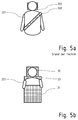
- Fig. 5a shows a seated vehicle occupant viewed from the front in a conventional vehicle.
- the upper body is restrained with a safety belt 300, which is very narrow in relation to the frontal body surface, so that the deceleration forces acting on the belt can act on a strip-shaped area of the body and cause local injuries there, even if the total deceleration due to the Accidents should be below critical limits.
- the head of the vehicle occupant 201 is not fully supported by the headrest 302 usually present, since already the projected area of the headrest 302 has a lower height than the head height. This results from the fact that the concave back of the head anyway does not lie flat and therefore rather punctual is supported.
- the neck area between the shoulder and the back of the head is rarely supported by the headrest.
- Fig. 5b shows a driver 201 from the front view in a standing room according to the invention, in turn, the support surfaces, which are provided by the collecting elements 31 and 36, are characterized by the hatched areas.
- the front and rear catch members 31, 33 are wider than the body of the rider 201 so as to be supported over the entire body width. Furthermore, a large part of the body height is supported, namely at least the area of the upper body to just below the shoulders, in order to ensure a certain freedom of movement. Further support to the leg and abdomen area may be provided by the downwardly extending front catch, which is not shown here.
- the rear side of the body is completely covered, because even there, the catch element 33 is made wider than the body of the driver 201. In the headrest 36, the width can be slightly reduced, especially to not completely obstruct the view of the rear passengers
- the collecting element 33 in the back of the driver 201 ensures a planar contact with the body and thus distributes the deceleration forces uniformly over the entire body, even if this is less critical in the back region due to the musculature which is quite strong there in the front trunk area with the organs lying there.
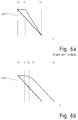
- Fig. 6a shows a schematic representation of the velocity profile of a vehicle according to the prior art over time as a solid line and a vehicle occupant as a dashed line.
- the speed of a vehicle occupant is shown by the dashed line.
- the body At the time of the accident t 0, the body has the same speed as the vehicle in which it is seated. However, it takes a time until a time t 0 , which corresponds to the so-called beltless.
- the body first moves in space with the speed imposed on it before the restraint systems take effect and the deceleration process begins.
- the period from T 0 to T 1 can be shortened by improved restraint system, such as belt tensioners, airbags, etc., which is known per se and therefore needs no further explanation here.
- Fig. 6b the deceleration deceleration of a vehicle according to the invention and a vehicle occupant traveling on a standing place therein are shown.
- the idealized assumption applies that the vehicle speed existing at the time of the accident t 0 is linearly reduced to zero at a standstill time t S.
- the deceleration of the body of the vehicle occupant is again shown by the dashed line.
- time t 1 to which the body is moved on at the original cruising speed.
- the length of time essentially depends on how close the vehicle occupant is to the catching elements.
- the loss of time between t 0 and t 1 causes the occupant load is higher than the vehicle load, but it does not depend significantly on the invention, since the further course of the delay is determined by the collecting elements and not through the vehicle compartment.
- the body In the phase between t 1 and t 2 , the body is stopped at the front layer of the collecting element. First, there is the effect of the surface conditioning of all parts of the body in order to let the pressure load act evenly on the body. Due to the low slope, the delay effect in this phase is still low.
- Fig. 6b only a main period of time between the time t 3 at which the last layer is first compressed and the stall of the body above ground at time t 4 is shown.
- the deceleration to there is approximately the same as that of the vehicle cell, but delayed in time, since the elastically or plastically deformable layers in the collecting elements virtually provide a pure personal crumple zone in which the body can move relative to the crashed vehicle, so that he just later comes to an absolute standstill as the vehicle itself.
Applications Claiming Priority (1)
| Application Number | Priority Date | Filing Date | Title |
|---|---|---|---|
| DE102015115200.2A DE102015115200B4 (de) | 2015-09-09 | 2015-09-09 | Fahrzeug mit wenigstens einem Stehplatz für einen stehenden Fahrer und/oder einen stehenden Fahrgast |
Publications (2)
| Publication Number | Publication Date |
|---|---|
| EP3141436A1 true EP3141436A1 (fr) | 2017-03-15 |
| EP3141436B1 EP3141436B1 (fr) | 2019-05-08 |
Family
ID=56893850
Family Applications (1)
| Application Number | Title | Priority Date | Filing Date |
|---|---|---|---|
| EP16188034.9A Active EP3141436B1 (fr) | 2015-09-09 | 2016-09-09 | Vehicule comprenant au moins une place debout pour un conducteur debout et/ou un passager debout |
Country Status (2)
| Country | Link |
|---|---|
| EP (1) | EP3141436B1 (fr) |
| DE (1) | DE102015115200B4 (fr) |
Cited By (4)
| Publication number | Priority date | Publication date | Assignee | Title |
|---|---|---|---|---|
| CN108802350A (zh) * | 2018-09-04 | 2018-11-13 | 山东交通学院 | 一种用于直线循环式加速加载试验设备的h形导轨 |
| JP2020050071A (ja) * | 2018-09-26 | 2020-04-02 | トヨタ自動車株式会社 | 車両の乗員保護構造 |
| WO2021069380A1 (fr) * | 2019-10-10 | 2021-04-15 | Zf Friedrichshafen Ag | Protection des occupants d'un véhicule automobile |
| CN114379435A (zh) * | 2022-02-14 | 2022-04-22 | 伍洪少 | 一种可站立驾驶的大客车、大货车 |
Citations (12)
| Publication number | Priority date | Publication date | Assignee | Title |
|---|---|---|---|---|
| DE836748C (de) * | 1950-10-27 | 1952-04-17 | Franz Derwahl | Sicherheitsanordnung fuer Insassen in Fahrzeugen, insbesondere in Personenkraftfahrzeugen |
| US3603535A (en) * | 1968-11-13 | 1971-09-07 | Maurice Depolo | Lifesaving support system |
| JPS62101586A (ja) | 1985-10-30 | 1987-05-12 | Yamaha Motor Co Ltd | 四輪立乗りゴルフカ−ト |
| DE19518116A1 (de) * | 1994-05-20 | 1995-11-23 | Linde Ag | Flurförderzeug mit einem Fahrerstand |
| DE19544266A1 (de) * | 1994-12-23 | 1996-06-27 | Ford Werke Ag | Energieabsorbierende Fahrzeugtür |
| EP0568775B1 (fr) | 1992-05-04 | 1998-04-01 | Jungheinrich Aktiengesellschaft | Plate-forme de support d'un conducteur restant debout sur un chariot élévateur |
| DE19814548C1 (de) | 1998-04-01 | 1999-07-22 | Schimmelpfennig Karl Heinz | Sitzanordnung für der Personenbeförderung dienende Fahrzeuge |
| WO2000038959A1 (fr) * | 1998-12-30 | 2000-07-06 | Automotive Systems Laboratory, Inc. | Systeme de detection d'occupant |
| EP1127788A1 (fr) * | 2000-02-23 | 2001-08-29 | EADS Airbus GmbH | Disposition de passagers dans la cabine d'un aéronef |
| WO2006032275A2 (fr) | 2004-09-24 | 2006-03-30 | Lorens Peter Iversen | Dispositif de transport |
| CA2696407A1 (fr) | 2009-05-06 | 2010-11-06 | Sears Manufacturing Company | Siege de vehicule |
| DE102013214779A1 (de) * | 2013-07-29 | 2015-01-29 | Siemens Aktiengesellschaft | Ergonomisch flexibler Fahrerstand eines Schienenfahrzeugs |
Family Cites Families (1)
| Publication number | Priority date | Publication date | Assignee | Title |
|---|---|---|---|---|
| IT979462B (it) | 1972-03-03 | 1974-09-30 | Espenso L | Terminale per connessioni elettriche |
-
2015
- 2015-09-09 DE DE102015115200.2A patent/DE102015115200B4/de active Active
-
2016
- 2016-09-09 EP EP16188034.9A patent/EP3141436B1/fr active Active
Patent Citations (12)
| Publication number | Priority date | Publication date | Assignee | Title |
|---|---|---|---|---|
| DE836748C (de) * | 1950-10-27 | 1952-04-17 | Franz Derwahl | Sicherheitsanordnung fuer Insassen in Fahrzeugen, insbesondere in Personenkraftfahrzeugen |
| US3603535A (en) * | 1968-11-13 | 1971-09-07 | Maurice Depolo | Lifesaving support system |
| JPS62101586A (ja) | 1985-10-30 | 1987-05-12 | Yamaha Motor Co Ltd | 四輪立乗りゴルフカ−ト |
| EP0568775B1 (fr) | 1992-05-04 | 1998-04-01 | Jungheinrich Aktiengesellschaft | Plate-forme de support d'un conducteur restant debout sur un chariot élévateur |
| DE19518116A1 (de) * | 1994-05-20 | 1995-11-23 | Linde Ag | Flurförderzeug mit einem Fahrerstand |
| DE19544266A1 (de) * | 1994-12-23 | 1996-06-27 | Ford Werke Ag | Energieabsorbierende Fahrzeugtür |
| DE19814548C1 (de) | 1998-04-01 | 1999-07-22 | Schimmelpfennig Karl Heinz | Sitzanordnung für der Personenbeförderung dienende Fahrzeuge |
| WO2000038959A1 (fr) * | 1998-12-30 | 2000-07-06 | Automotive Systems Laboratory, Inc. | Systeme de detection d'occupant |
| EP1127788A1 (fr) * | 2000-02-23 | 2001-08-29 | EADS Airbus GmbH | Disposition de passagers dans la cabine d'un aéronef |
| WO2006032275A2 (fr) | 2004-09-24 | 2006-03-30 | Lorens Peter Iversen | Dispositif de transport |
| CA2696407A1 (fr) | 2009-05-06 | 2010-11-06 | Sears Manufacturing Company | Siege de vehicule |
| DE102013214779A1 (de) * | 2013-07-29 | 2015-01-29 | Siemens Aktiengesellschaft | Ergonomisch flexibler Fahrerstand eines Schienenfahrzeugs |
Cited By (6)
| Publication number | Priority date | Publication date | Assignee | Title |
|---|---|---|---|---|
| CN108802350A (zh) * | 2018-09-04 | 2018-11-13 | 山东交通学院 | 一种用于直线循环式加速加载试验设备的h形导轨 |
| CN108802350B (zh) * | 2018-09-04 | 2023-05-30 | 山东交通学院 | 一种用于直线循环式加速加载试验设备的h形导轨 |
| JP2020050071A (ja) * | 2018-09-26 | 2020-04-02 | トヨタ自動車株式会社 | 車両の乗員保護構造 |
| WO2021069380A1 (fr) * | 2019-10-10 | 2021-04-15 | Zf Friedrichshafen Ag | Protection des occupants d'un véhicule automobile |
| US11731577B2 (en) | 2019-10-10 | 2023-08-22 | Zf Friedrichshafen Ag | Passenger protection for a motor vehicle |
| CN114379435A (zh) * | 2022-02-14 | 2022-04-22 | 伍洪少 | 一种可站立驾驶的大客车、大货车 |
Also Published As
| Publication number | Publication date |
|---|---|
| DE102015115200A1 (de) | 2017-03-09 |
| DE102015115200B4 (de) | 2022-07-21 |
| EP3141436B1 (fr) | 2019-05-08 |
Similar Documents
| Publication | Publication Date | Title |
|---|---|---|
| EP3141436B1 (fr) | Vehicule comprenant au moins une place debout pour un conducteur debout et/ou un passager debout | |
| DE2338026C3 (de) | Aufprallschutzvorrichtung für den Fahrer eines Kraftfahrzeuges | |
| DE69832295T2 (de) | Leicht auszustossender sitz sowie endo-skelettaler balken zum schutz von unfällen | |
| DE2456028A1 (de) | Sitzsystem fuer fahrzeuge | |
| EP1095815A1 (fr) | Seat with backrest for an automotive vehicle | |
| DE102008043617A1 (de) | Fahrzeugsitz | |
| EP2855268B1 (fr) | Siège d'avion pourvu d'un ensemble siège | |
| DE102018130323B4 (de) | Fahrzeugsitz | |
| EP0703120B1 (fr) | Elément de paroi absorbant des chocs | |
| WO2019180213A1 (fr) | Ensemble formant siège de véhicule | |
| DE2725577C2 (de) | Auf übliche Fahrzeugsitze aufsetzbare Rückhaltevorrichtung für Kinder | |
| DE102018204461A1 (de) | Fahrzeugsitz | |
| DE1680055A1 (de) | Kraftfahrzeug | |
| DE60206695T2 (de) | Kraftfahrzeug Insassenschutzsystem | |
| DE10243354B4 (de) | Kraftfahrzeug-Insassenschutzsystem | |
| DE10030549A1 (de) | Fahrzeugsitz | |
| DE10224831B4 (de) | Kraftfahrzeug und Verfahren zur Reduzierung der Belastung von Insassen eines Kraftfahrzeugs bei einem Zusammenstoss mit einem Hindernis | |
| DE19749780A1 (de) | Sitz-integriertes Rückhaltesystem mit Energieabsorption-Management bei Fahrzeug, Zug und Flugzeug | |
| WO2008031605A1 (fr) | Dispositif de sécurité pour véhicules | |
| DE10150719A1 (de) | Fahrzeugsitz und Verfahren zur Ansteuerung desselben | |
| DE2856437A1 (de) | Sicherheitseinrichtung fuer fahrzeuge, insbesondere personenkraftfahrzeuge | |
| EP0551279B1 (fr) | Installation de securite dans un vehicule | |
| DE2216378A1 (de) | Auffangsitz | |
| DE10061043A1 (de) | Sicherheitsvorrichtung an Fahrzeugsitzen | |
| DE102006048978A1 (de) | Fahrzeugsitz und Verfahren zur Veränderung der Sitzposition eines Fahrzeuginsassen |
Legal Events
| Date | Code | Title | Description |
|---|---|---|---|
| PUAI | Public reference made under article 153(3) epc to a published international application that has entered the european phase |
Free format text: ORIGINAL CODE: 0009012 |
|
| STAA | Information on the status of an ep patent application or granted ep patent |
Free format text: STATUS: THE APPLICATION HAS BEEN PUBLISHED |
|
| AK | Designated contracting states |
Kind code of ref document: A1 Designated state(s): AL AT BE BG CH CY CZ DE DK EE ES FI FR GB GR HR HU IE IS IT LI LT LU LV MC MK MT NL NO PL PT RO RS SE SI SK SM TR |
|
| AX | Request for extension of the european patent |
Extension state: BA ME |
|
| STAA | Information on the status of an ep patent application or granted ep patent |
Free format text: STATUS: REQUEST FOR EXAMINATION WAS MADE |
|
| 17P | Request for examination filed |
Effective date: 20170915 |
|
| RBV | Designated contracting states (corrected) |
Designated state(s): AL AT BE BG CH CY CZ DE DK EE ES FI FR GB GR HR HU IE IS IT LI LT LU LV MC MK MT NL NO PL PT RO RS SE SI SK SM TR |
|
| GRAP | Despatch of communication of intention to grant a patent |
Free format text: ORIGINAL CODE: EPIDOSNIGR1 |
|
| STAA | Information on the status of an ep patent application or granted ep patent |
Free format text: STATUS: GRANT OF PATENT IS INTENDED |
|
| RIC1 | Information provided on ipc code assigned before grant |
Ipc: B64D 11/06 20060101ALI20181004BHEP Ipc: B60R 21/16 20060101ALI20181004BHEP Ipc: B60R 21/00 20060101ALN20181004BHEP Ipc: B60N 2/24 20060101ALI20181004BHEP Ipc: B60R 21/04 20060101ALI20181004BHEP Ipc: B60R 21/02 20060101AFI20181004BHEP Ipc: B64D 11/00 20060101ALI20181004BHEP Ipc: B60R 21/045 20060101ALN20181004BHEP Ipc: B60R 21/231 20110101ALN20181004BHEP |
|
| INTG | Intention to grant announced |
Effective date: 20181030 |
|
| GRAJ | Information related to disapproval of communication of intention to grant by the applicant or resumption of examination proceedings by the epo deleted |
Free format text: ORIGINAL CODE: EPIDOSDIGR1 |
|
| STAA | Information on the status of an ep patent application or granted ep patent |
Free format text: STATUS: REQUEST FOR EXAMINATION WAS MADE |
|
| GRAS | Grant fee paid |
Free format text: ORIGINAL CODE: EPIDOSNIGR3 |
|
| STAA | Information on the status of an ep patent application or granted ep patent |
Free format text: STATUS: GRANT OF PATENT IS INTENDED |
|
| GRAP | Despatch of communication of intention to grant a patent |
Free format text: ORIGINAL CODE: EPIDOSNIGR1 |
|
| INTC | Intention to grant announced (deleted) | ||
| RIC1 | Information provided on ipc code assigned before grant |
Ipc: B64D 11/06 20060101ALI20190227BHEP Ipc: B60R 21/231 20110101ALN20190227BHEP Ipc: B60R 21/16 20060101ALI20190227BHEP Ipc: B60R 21/00 20060101ALN20190227BHEP Ipc: B60N 2/24 20060101ALI20190227BHEP Ipc: B60R 21/04 20060101ALI20190227BHEP Ipc: B60R 21/045 20060101ALN20190227BHEP Ipc: B60R 21/02 20060101AFI20190227BHEP Ipc: B64D 11/00 20060101ALI20190227BHEP |
|
| GRAA | (expected) grant |
Free format text: ORIGINAL CODE: 0009210 |
|
| STAA | Information on the status of an ep patent application or granted ep patent |
Free format text: STATUS: THE PATENT HAS BEEN GRANTED |
|
| RIC1 | Information provided on ipc code assigned before grant |
Ipc: B60N 2/24 20060101ALI20190314BHEP Ipc: B60R 21/02 20060101AFI20190314BHEP Ipc: B60R 21/04 20060101ALI20190314BHEP Ipc: B64D 11/00 20060101ALI20190314BHEP Ipc: B60R 21/045 20060101ALN20190314BHEP Ipc: B64D 11/06 20060101ALI20190314BHEP Ipc: B60R 21/16 20060101ALI20190314BHEP Ipc: B60R 21/231 20110101ALN20190314BHEP Ipc: B60R 21/00 20060101ALN20190314BHEP |
|
| INTG | Intention to grant announced |
Effective date: 20190326 |
|
| AK | Designated contracting states |
Kind code of ref document: B1 Designated state(s): AL AT BE BG CH CY CZ DE DK EE ES FI FR GB GR HR HU IE IS IT LI LT LU LV MC MK MT NL NO PL PT RO RS SE SI SK SM TR |
|
| REG | Reference to a national code |
Ref country code: GB Ref legal event code: FG4D Free format text: NOT ENGLISH |
|
| REG | Reference to a national code |
Ref country code: CH Ref legal event code: EP Ref country code: AT Ref legal event code: REF Ref document number: 1129647 Country of ref document: AT Kind code of ref document: T Effective date: 20190515 |
|
| REG | Reference to a national code |
Ref country code: DE Ref legal event code: R096 Ref document number: 502016004535 Country of ref document: DE |
|
| REG | Reference to a national code |
Ref country code: IE Ref legal event code: FG4D Free format text: LANGUAGE OF EP DOCUMENT: GERMAN |
|
| REG | Reference to a national code |
Ref country code: NL Ref legal event code: MP Effective date: 20190508 |
|
| REG | Reference to a national code |
Ref country code: LT Ref legal event code: MG4D |
|
| PG25 | Lapsed in a contracting state [announced via postgrant information from national office to epo] |
Ref country code: HR Free format text: LAPSE BECAUSE OF FAILURE TO SUBMIT A TRANSLATION OF THE DESCRIPTION OR TO PAY THE FEE WITHIN THE PRESCRIBED TIME-LIMIT Effective date: 20190508 Ref country code: SE Free format text: LAPSE BECAUSE OF FAILURE TO SUBMIT A TRANSLATION OF THE DESCRIPTION OR TO PAY THE FEE WITHIN THE PRESCRIBED TIME-LIMIT Effective date: 20190508 Ref country code: NL Free format text: LAPSE BECAUSE OF FAILURE TO SUBMIT A TRANSLATION OF THE DESCRIPTION OR TO PAY THE FEE WITHIN THE PRESCRIBED TIME-LIMIT Effective date: 20190508 Ref country code: LT Free format text: LAPSE BECAUSE OF FAILURE TO SUBMIT A TRANSLATION OF THE DESCRIPTION OR TO PAY THE FEE WITHIN THE PRESCRIBED TIME-LIMIT Effective date: 20190508 Ref country code: ES Free format text: LAPSE BECAUSE OF FAILURE TO SUBMIT A TRANSLATION OF THE DESCRIPTION OR TO PAY THE FEE WITHIN THE PRESCRIBED TIME-LIMIT Effective date: 20190508 Ref country code: NO Free format text: LAPSE BECAUSE OF FAILURE TO SUBMIT A TRANSLATION OF THE DESCRIPTION OR TO PAY THE FEE WITHIN THE PRESCRIBED TIME-LIMIT Effective date: 20190808 Ref country code: FI Free format text: LAPSE BECAUSE OF FAILURE TO SUBMIT A TRANSLATION OF THE DESCRIPTION OR TO PAY THE FEE WITHIN THE PRESCRIBED TIME-LIMIT Effective date: 20190508 Ref country code: PT Free format text: LAPSE BECAUSE OF FAILURE TO SUBMIT A TRANSLATION OF THE DESCRIPTION OR TO PAY THE FEE WITHIN THE PRESCRIBED TIME-LIMIT Effective date: 20190908 Ref country code: AL Free format text: LAPSE BECAUSE OF FAILURE TO SUBMIT A TRANSLATION OF THE DESCRIPTION OR TO PAY THE FEE WITHIN THE PRESCRIBED TIME-LIMIT Effective date: 20190508 |
|
| PG25 | Lapsed in a contracting state [announced via postgrant information from national office to epo] |
Ref country code: LV Free format text: LAPSE BECAUSE OF FAILURE TO SUBMIT A TRANSLATION OF THE DESCRIPTION OR TO PAY THE FEE WITHIN THE PRESCRIBED TIME-LIMIT Effective date: 20190508 Ref country code: GR Free format text: LAPSE BECAUSE OF FAILURE TO SUBMIT A TRANSLATION OF THE DESCRIPTION OR TO PAY THE FEE WITHIN THE PRESCRIBED TIME-LIMIT Effective date: 20190809 Ref country code: RS Free format text: LAPSE BECAUSE OF FAILURE TO SUBMIT A TRANSLATION OF THE DESCRIPTION OR TO PAY THE FEE WITHIN THE PRESCRIBED TIME-LIMIT Effective date: 20190508 Ref country code: BG Free format text: LAPSE BECAUSE OF FAILURE TO SUBMIT A TRANSLATION OF THE DESCRIPTION OR TO PAY THE FEE WITHIN THE PRESCRIBED TIME-LIMIT Effective date: 20190808 |
|
| PG25 | Lapsed in a contracting state [announced via postgrant information from national office to epo] |
Ref country code: RO Free format text: LAPSE BECAUSE OF FAILURE TO SUBMIT A TRANSLATION OF THE DESCRIPTION OR TO PAY THE FEE WITHIN THE PRESCRIBED TIME-LIMIT Effective date: 20190508 Ref country code: CZ Free format text: LAPSE BECAUSE OF FAILURE TO SUBMIT A TRANSLATION OF THE DESCRIPTION OR TO PAY THE FEE WITHIN THE PRESCRIBED TIME-LIMIT Effective date: 20190508 Ref country code: DK Free format text: LAPSE BECAUSE OF FAILURE TO SUBMIT A TRANSLATION OF THE DESCRIPTION OR TO PAY THE FEE WITHIN THE PRESCRIBED TIME-LIMIT Effective date: 20190508 Ref country code: EE Free format text: LAPSE BECAUSE OF FAILURE TO SUBMIT A TRANSLATION OF THE DESCRIPTION OR TO PAY THE FEE WITHIN THE PRESCRIBED TIME-LIMIT Effective date: 20190508 Ref country code: SK Free format text: LAPSE BECAUSE OF FAILURE TO SUBMIT A TRANSLATION OF THE DESCRIPTION OR TO PAY THE FEE WITHIN THE PRESCRIBED TIME-LIMIT Effective date: 20190508 |
|
| REG | Reference to a national code |
Ref country code: DE Ref legal event code: R097 Ref document number: 502016004535 Country of ref document: DE |
|
| PG25 | Lapsed in a contracting state [announced via postgrant information from national office to epo] |
Ref country code: IT Free format text: LAPSE BECAUSE OF FAILURE TO SUBMIT A TRANSLATION OF THE DESCRIPTION OR TO PAY THE FEE WITHIN THE PRESCRIBED TIME-LIMIT Effective date: 20190508 Ref country code: SM Free format text: LAPSE BECAUSE OF FAILURE TO SUBMIT A TRANSLATION OF THE DESCRIPTION OR TO PAY THE FEE WITHIN THE PRESCRIBED TIME-LIMIT Effective date: 20190508 |
|
| PLBE | No opposition filed within time limit |
Free format text: ORIGINAL CODE: 0009261 |
|
| STAA | Information on the status of an ep patent application or granted ep patent |
Free format text: STATUS: NO OPPOSITION FILED WITHIN TIME LIMIT |
|
| PG25 | Lapsed in a contracting state [announced via postgrant information from national office to epo] |
Ref country code: TR Free format text: LAPSE BECAUSE OF FAILURE TO SUBMIT A TRANSLATION OF THE DESCRIPTION OR TO PAY THE FEE WITHIN THE PRESCRIBED TIME-LIMIT Effective date: 20190508 |
|
| 26N | No opposition filed |
Effective date: 20200211 |
|
| PG25 | Lapsed in a contracting state [announced via postgrant information from national office to epo] |
Ref country code: PL Free format text: LAPSE BECAUSE OF FAILURE TO SUBMIT A TRANSLATION OF THE DESCRIPTION OR TO PAY THE FEE WITHIN THE PRESCRIBED TIME-LIMIT Effective date: 20190508 |
|
| PG25 | Lapsed in a contracting state [announced via postgrant information from national office to epo] |
Ref country code: SI Free format text: LAPSE BECAUSE OF FAILURE TO SUBMIT A TRANSLATION OF THE DESCRIPTION OR TO PAY THE FEE WITHIN THE PRESCRIBED TIME-LIMIT Effective date: 20190508 Ref country code: MC Free format text: LAPSE BECAUSE OF FAILURE TO SUBMIT A TRANSLATION OF THE DESCRIPTION OR TO PAY THE FEE WITHIN THE PRESCRIBED TIME-LIMIT Effective date: 20190508 |
|
| REG | Reference to a national code |
Ref country code: CH Ref legal event code: PL |
|
| PG25 | Lapsed in a contracting state [announced via postgrant information from national office to epo] |
Ref country code: LI Free format text: LAPSE BECAUSE OF NON-PAYMENT OF DUE FEES Effective date: 20190930 Ref country code: IE Free format text: LAPSE BECAUSE OF NON-PAYMENT OF DUE FEES Effective date: 20190909 Ref country code: LU Free format text: LAPSE BECAUSE OF NON-PAYMENT OF DUE FEES Effective date: 20190909 Ref country code: CH Free format text: LAPSE BECAUSE OF NON-PAYMENT OF DUE FEES Effective date: 20190930 |
|
| REG | Reference to a national code |
Ref country code: BE Ref legal event code: MM Effective date: 20190930 |
|
| PG25 | Lapsed in a contracting state [announced via postgrant information from national office to epo] |
Ref country code: BE Free format text: LAPSE BECAUSE OF NON-PAYMENT OF DUE FEES Effective date: 20190930 |
|
| GBPC | Gb: european patent ceased through non-payment of renewal fee |
Effective date: 20200909 |
|
| PG25 | Lapsed in a contracting state [announced via postgrant information from national office to epo] |
Ref country code: CY Free format text: LAPSE BECAUSE OF FAILURE TO SUBMIT A TRANSLATION OF THE DESCRIPTION OR TO PAY THE FEE WITHIN THE PRESCRIBED TIME-LIMIT Effective date: 20190508 |
|
| PG25 | Lapsed in a contracting state [announced via postgrant information from national office to epo] |
Ref country code: IS Free format text: LAPSE BECAUSE OF FAILURE TO SUBMIT A TRANSLATION OF THE DESCRIPTION OR TO PAY THE FEE WITHIN THE PRESCRIBED TIME-LIMIT Effective date: 20190908 |
|
| PG25 | Lapsed in a contracting state [announced via postgrant information from national office to epo] |
Ref country code: HU Free format text: LAPSE BECAUSE OF FAILURE TO SUBMIT A TRANSLATION OF THE DESCRIPTION OR TO PAY THE FEE WITHIN THE PRESCRIBED TIME-LIMIT; INVALID AB INITIO Effective date: 20160909 Ref country code: FR Free format text: LAPSE BECAUSE OF NON-PAYMENT OF DUE FEES Effective date: 20190930 Ref country code: MT Free format text: LAPSE BECAUSE OF FAILURE TO SUBMIT A TRANSLATION OF THE DESCRIPTION OR TO PAY THE FEE WITHIN THE PRESCRIBED TIME-LIMIT Effective date: 20190508 |
|
| PG25 | Lapsed in a contracting state [announced via postgrant information from national office to epo] |
Ref country code: GB Free format text: LAPSE BECAUSE OF NON-PAYMENT OF DUE FEES Effective date: 20200909 |
|
| PG25 | Lapsed in a contracting state [announced via postgrant information from national office to epo] |
Ref country code: MK Free format text: LAPSE BECAUSE OF FAILURE TO SUBMIT A TRANSLATION OF THE DESCRIPTION OR TO PAY THE FEE WITHIN THE PRESCRIBED TIME-LIMIT Effective date: 20190508 |
|
| REG | Reference to a national code |
Ref country code: AT Ref legal event code: MM01 Ref document number: 1129647 Country of ref document: AT Kind code of ref document: T Effective date: 20210909 |
|
| PG25 | Lapsed in a contracting state [announced via postgrant information from national office to epo] |
Ref country code: AT Free format text: LAPSE BECAUSE OF NON-PAYMENT OF DUE FEES Effective date: 20210909 |
|
| PGFP | Annual fee paid to national office [announced via postgrant information from national office to epo] |
Ref country code: DE Payment date: 20230919 Year of fee payment: 8 |
|
| REG | Reference to a national code |
Ref country code: DE Ref legal event code: R082 Ref document number: 502016004535 Country of ref document: DE Representative=s name: BOEHMERT & BOEHMERT ANWALTSPARTNERSCHAFT MBB -, DE |